Don9of11
-
Posts
718 -
Joined
-
Last visited
Content Type
Profiles
Forums
Gallery
Events
Everything posted by Don9of11
-
Brig USS Enterprise 1799 info gathering
Don9of11 replied to CharlieZardoz's topic in Nautical/Naval History
The drawings I have seen posted remind of the the drawings found in The Built-Up Ship Model by Charles Davis. Also, if you have the novel Six Frigates by Ian Toll, there are several passages about the Enterprise, her commanders and engagements. -
3D printer at Home Depot
Don9of11 replied to twintrow's topic in CAD and 3D Modelling/Drafting Plans with Software
I was going to recomend that whenever you look at these types of machines you do your research on the quality of the finished product or it's resolution. A 100 micron finish isn't very smooth. A machined surface of this specification would likely show machining marks or steps, they would tend to blur together but it's a very rough surface. So I guess some additional processing would be required. -
online 3d CAD
Don9of11 replied to Don9of11's topic in CAD and 3D Modelling/Drafting Plans with Software
I was informed of another online CAD program produced by Autodesk the makers of Autocad and Inventor. The program is called Fusion 360. http://www.autodesk.com/products/fusion-360/overview Unlike the OnShape program, Fusion 360 is downloadable. They offer a 30 day free trial and then to continue using it you need to subscribe. Autodesk offers an annual subscription of $25/mo or $40/mo to use it on an as needed basis. Compared to OnShape which has no software to download and they offer a free subcription but limits the number of active part files you can work on at any-one-time. To gain access to unlimited part files the cost is $100/mo. Fusion 360 and OnShape are both parametric CAD programs meaning simply that if you update a dimension in the the model, it updates and changes automatically, no need to redraw anything. Both programs are cloud-based meaning in the simplist of terms, they operate across the internet. OnShape is in the beta stage, does not have the capability of making drawings yet whereas Fusion 360 is fully developed. Each program offer's mobile device support such as your iPhone or iPad, Android or Windows tablet. This is the future of CAD, these programs alone will force the giants in the industry like SolidWorks and Inventor to reduce their cost and maintence fees or face loosing a large part of their user base. -
Brig USS Enterprise 1799 info gathering
Don9of11 replied to CharlieZardoz's topic in Nautical/Naval History
When I was building my model of the Enterprise which was the kit by Constructo (#80822) I came across a couple publications in my research. The first was an article that appeared in the winter 1999 issue of the Journal Of The War Of 1812 by Michael Bosworth. I don't think this paper is in print anymore so if you would like a copy let me know. The second, was an article I found on a website I believe was called The Ancient Mariner, again I don't think this paper is available anymore either. And thirdly, is a book you can download from Google called "The Lucky Little Enterprise" and Her Successors In the United States Navy 1776-1900 by Fredrick Stanhope Hill. This book is also available through the Internet Archeive https://archive.org/details/luckylittleenter00hilliala. I have some photos of my build here and here http://howefamily.com/zellars_progress_photos/zellars.asp -
I recently learned about a browser based 3D CAD program which is able to run on Windows and Mac platforms as well as mobile devices. https://www.onshape.com/ This program offers a free version and a paid version. So I signed up for the free version and quickyly learned that my 10 yr old 64bit computer's Radeon graphics card does not support webGL which is required to run this program on your web browser, tablet or phone. Also, your browser must also support webGL and most modern web browsers like Firefox and Chrome support this feature but some browsers disable this feature because of performance issues. I learned too that some graphics cards are supported and some are not. The program from what I can tell is in a Beta production status. Despite all these various requirements it look's like a vary robust 3D CAD program. Here is a link about webGL https://www.khronos.org/webgl/
-
Drawing with quota, exist?
Don9of11 replied to Jhenrique's topic in CAD and 3D Modelling/Drafting Plans with Software
You seem to have your mind set on a galleon or ship of sail but you might want to check out these engineering drawings of a modern navy vessel. http://destroyerhistory.org/destroyers/drawings/ -
Alan, when did you switch to Inventor? I have heard good things about it from a guy I work with. He say's in many ways it's better than SolidWorks. I have to admit after working with SW 2015 for about 2 months now it has many of the same core issues it had 15 years ago, but there have been some nice features added. I know this has nothing to do with your model but it save me from asking whether you are using splines or not for laying off your hull sections.
-
Excellent work Alan, it's always good to see how your progressing and your approach to solving the hull development.
-
I was at an estate sale today and picked up a copy of The Bounty Trilogy - Wyeth Edition by Charles Nordhoff & James Norman Hall for $1. It was originally printed 1932 and this copy was printed by the Grosset & Dunlap, Publishers with permission of the Little, Brown and Company, 1945. It has some nice color illustrations and the book consist of the stories of the Mutiny On The Bounty, Men Against the Sea and Pitcairn's Island. The inside cover contains a map of the route taken by the Bounty's Launch and the back inside cover a map of the Bounty's route. This should make for a good read.
-
Beautiful work Alan, keep the pics coming! I'm following your build with great interest.
-
I've had the pleasure of training die designers in the forging industry on 2D and 3D CAD programs and the best advice I can give to learning any CAD program is to start with simple objects, the reasoning is so you become familiar with the menu, the tools and how to use them. The tendency for first time users is to start off with something big or complicated and you become frustrated or loose interest because you don't know how to use the menu or CAD features and ultimately the CAD program ends up in the wood pile.
-
I have used DraftSight as well and it is and old version of Autocad that has been modified by Dassult Systems. So in some sense it is the closest thing to Autocad. I also found some short comings especially with spline curves and making the ends tangent to other curves. Free Cad is metric only, no inches.
-
American Gunboat - 3d Design
Don9of11 replied to Kalium's topic in CAD and 3D Modelling/Drafting Plans with Software
My question which might seem off topic but how did you set the material property; are you using a wood material? I take it that these are SW renders? -
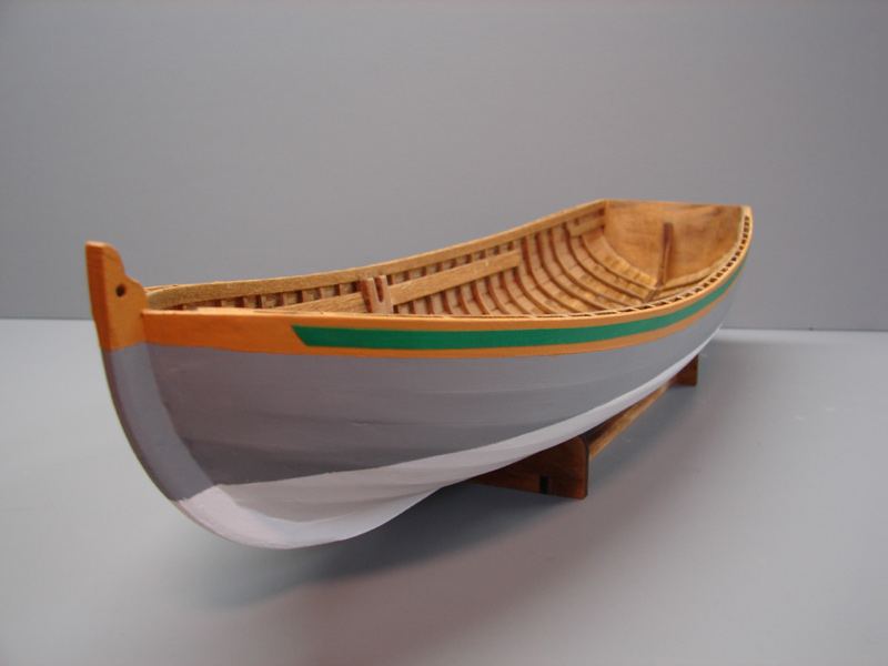
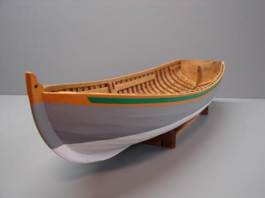
Thank you Keith, I used Minwax Golden Oak #210B. The model shown is from Model Expo and the wood is basswood. I picked up a little can at my local hardware store. You can see the full line of Minwax products at http://www.minwax.com/wood-products/stains-color-guide/ I have build log at http://shipmodeling.net/photopost/showgallery.php?cat=1378 Hope that helps.
-
I used green auto pin striping instead of paint for my Bounty Launch.
-
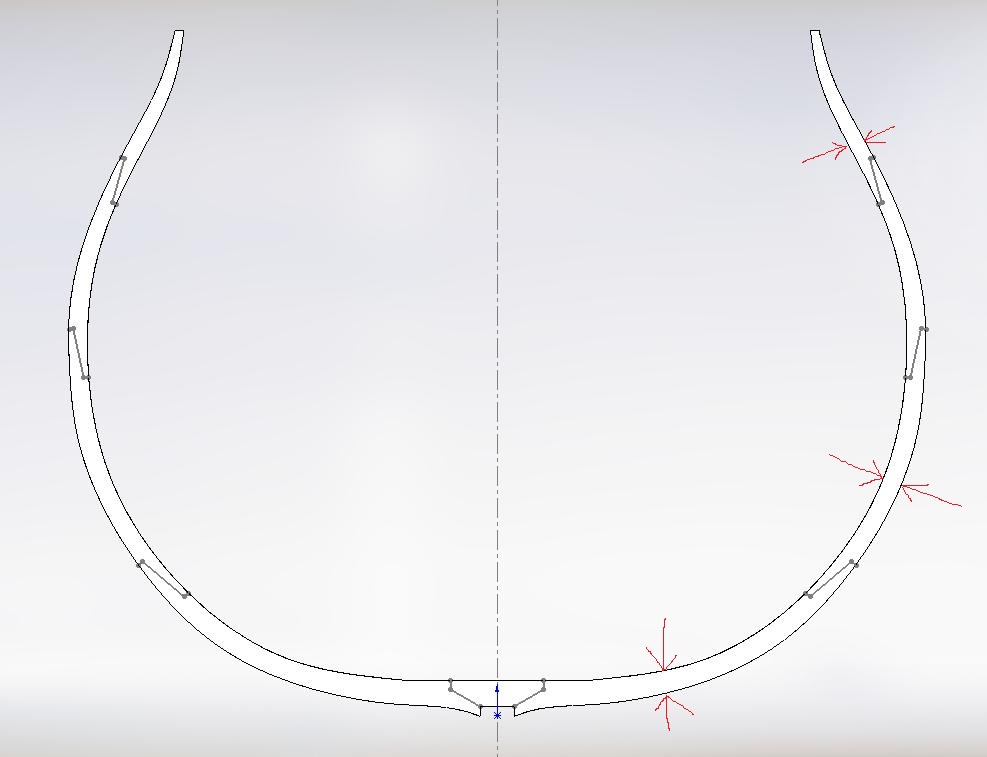
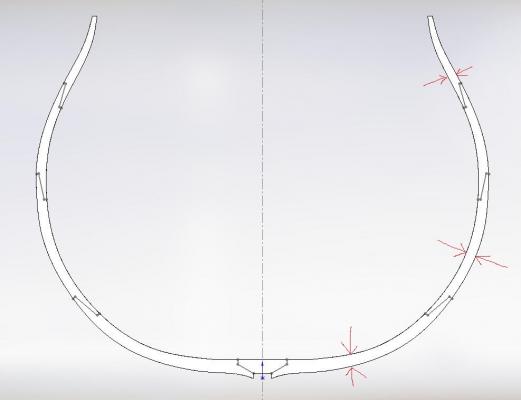
Alan, may I ask how you determine/set the thickness of the frame as I marked on your sketch? Is it an arbitrary distances or is this something that is called out in the contract?
-
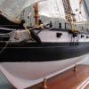
You're right. I found that getting the edges of the flag lined up and making sure the stripes and stars were in the same position was critical before the glue set up. The glue also provided a bit of moister in the paper that made working the flag a little easier. I researched carefully the era of my ship build, the Lucky Little Enterprise circa 1799, and made sure I had the right number of stars and stripes. I used different size dowel rods and following Chuck Passaro's advice, tried to get really aggressive with it. I tried a couple of different "wave patterns until I settled in on one that I really liked. It all boils down to being patient, deliberate and no fear. Here is another photo from my work-in-progress collection.
-
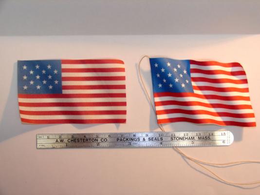
I printed mine using an inkjet printer on just plain copy paper. It was a double image, that is the flag had two halves or mirror copies. Once printed, I trimmed the flag and folded the paper then I used a glue stick to bond everything together. From there I just kept working it until I got the desired form I wanted. These photos are about 5 years apart and though the background color is different (the gray background is more recent) the color of the flag has held up pretty well.


-
Solid Works Users ?
Don9of11 replied to Don9of11's topic in CAD and 3D Modelling/Drafting Plans with Software
OK, I'm opening a new part file in SW. I also opened my jpg image in MS Paint then using Ctrl + C and Ctrl + V tried to paste it back into SW and my version of says "The item on the clip board cannot be pasted here" So, I decided to open a drawing file and did the Ctrl + V; it imports the jpg image very nicely, no distortions or raggedy edges. But how do I get back to my part file so I can trace over it and create a sketch? ----- OK, after some trial and error, I got the jpg image to copy into a SW part file. However, the image is just part of the background so if you try and rotate the image, you can't and it's not associated with any plane. You can certainly resize it and granted there are no raggedy edges or distorted lines but it's quite useless in this state. -
Solid Works Users ?
Don9of11 replied to Don9of11's topic in CAD and 3D Modelling/Drafting Plans with Software
2826 x 690 @ 300 dpi -
Solid Works Users ?
Don9of11 replied to Don9of11's topic in CAD and 3D Modelling/Drafting Plans with Software
I just gave that a try Bob by creating a 300 dpi, 1bit image saved as a bmp and the results were a little worse as the image is grainer. Probably for the purposes of tracing my first efforts produced an image that is useable.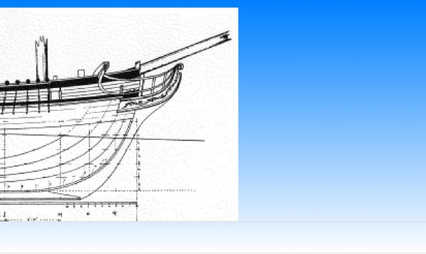
-
Solid Works Users ?
Don9of11 replied to Don9of11's topic in CAD and 3D Modelling/Drafting Plans with Software
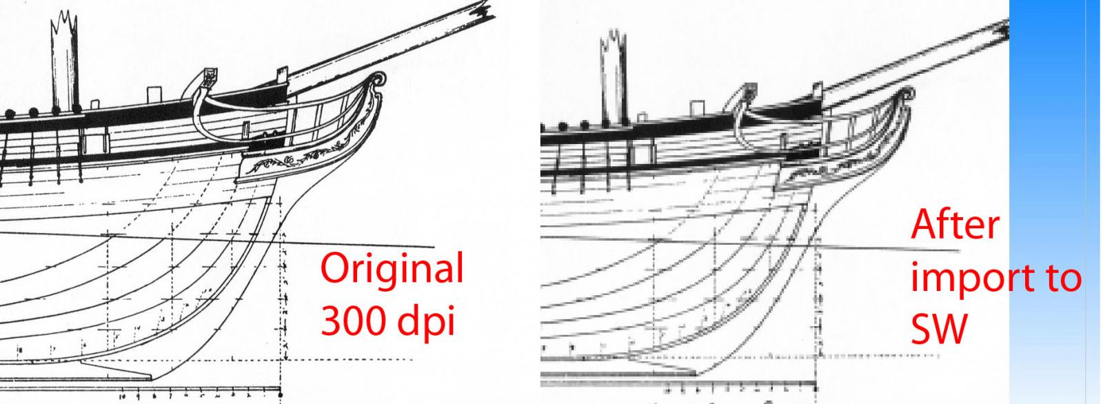
Here are some test results I made importing a image into SolidWorks 2004 The original image is 300 dpi jpg, RGB. I also used a tiff file at 300 dpi with the same results. Upon import SW enlarges the image by a factor of 3x and reduces the quality as near as I can figure to 72 dpi. I am able to resize the image back to the original dimensions but this does not restore the quality.
-
I have quick question for you. Do you ever import a sketch picture to SW with the intent to trace over it? If you do or have what steps did you take to prepare the image? Why does SW enlarge the image once you load it in?
-
I like what I see Alan, nice work on the transom area. Your insights and discoveries have been very helpful.
-
I agree with Rich, it's good job. You put a lot of work into your model so I would plug the open seams with wood putty, sand it down a little and then move on, it will look just fine. In time it will become a conversation piece not because of the planking but because of your attention to the rigging, sails, deck fittings. Of course you could always paint it, paint hide a multitude of sins