HOLIDAY DONATION DRIVE - SUPPORT MSW - DO YOUR PART TO KEEP THIS GREAT FORUM GOING! (Only 20 donations so far - C'mon guys!)
×

Don9of11
-
Posts
718 -
Joined
-
Last visited
Content Type
Profiles
Forums
Gallery
Events
Everything posted by Don9of11
-
The first thing a Captain learns is how to make decisions and since you're the Captain of your own ship the decision is yours. So take command and in the words of Captain Picard "make it so"... get those scallywags off to the side with a bucket and brush and paint away
-
 So 42 : 0 : 20 is somewhere in the neighborhood of 4700 lbs using the British hundredweight of 112lbs. Right?
 -
Thanks Jay. Speaking of this book, I seem to have forgotten how to read the weight of the gun. For example a 32# gun has a length of 9 : 8 which I think is read as 9 feet 8 inches and the weight is given as 42 : 0 : 20. Do you remember how this is read?
-
I've had a this book in my collection for a few years now and thought I would post a quick review. I have a printed copy I ordered through Amazon but it is now available via Google. I have found it to be a nice addition to my library and instrumental in making the gun carriages for my Enterprise of 1799. http://books.google.com/books/about/A_Treatise_of_Artillery.html?id=vylEAAAAYAAJ This book was originally published in 1780 and this is the 3rd Edition. It covers everything dealing with the general construction of brass and iron guns, mortars and howitzers used by ships and on land. It reveals how to calculate the dimensions of all carriages and beds used in artillery with numerous charts and illustrations. It covers both English and French guns. Discusses how much powder was used and the range in yards depending if it be a long gun or short gun and how much powder. It gives very specific details on how to calculate the diameter of the shot, the caliber of the gun, and the thickness of the metal and well...it contains a wealth of information for the model ship builder intent on making their own cannons and carriages or who is simply interested in learning more about the construction of period ship guns.
-
Ben, I found a good resource for ship terms, there is a book which is a free download from Google called "A compendium of Naval Architecture, arranged in Questions and Answers" by Robert Brindley. It was published around 1832.
-
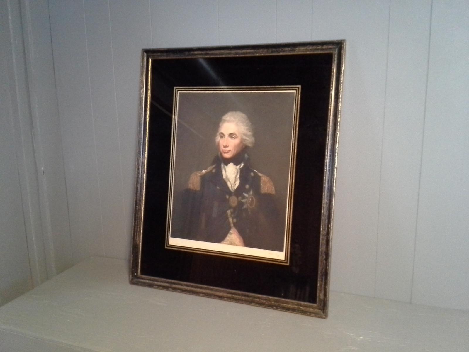
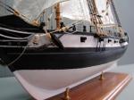
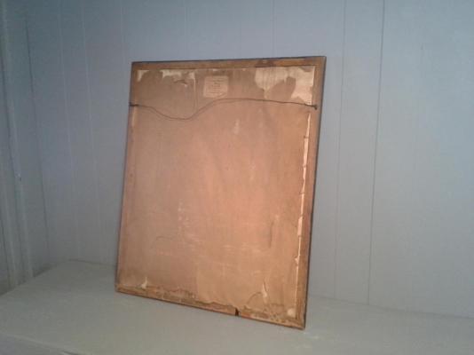
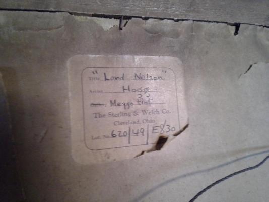
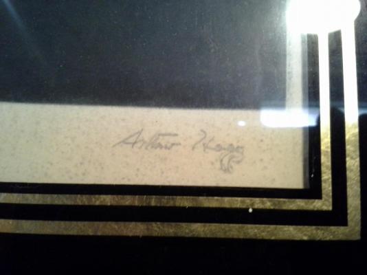
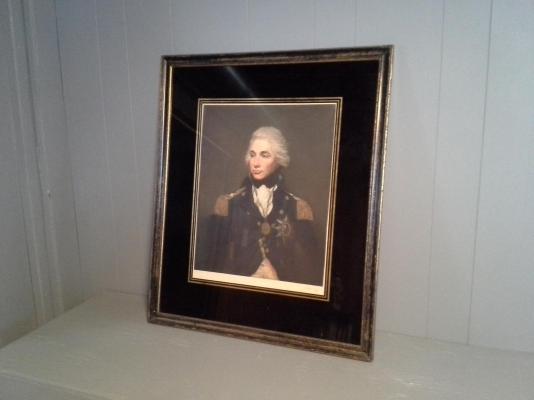
I was working an estate sale today an came across this painting entitled "Lord Nelson". The artist is Arthur Hogg. It looks like a reprint to me but I know nothing about art. The front of the frame looks in good condition but the back of the frame is in bad shape. I picked it up for $5. Anyone know anything about this artist or the value of the print? If this is the wrong forum, please move and edit the title.
-
He looks a little like Trevor Howard who starred as the Captain of the Bounty in the movie Mutiny on the Bounty with Marlon Brando
-
I have always had good luck at the FedEx/Kinko's office stores near me. They have scanning and printing capabilities at a good price.
-
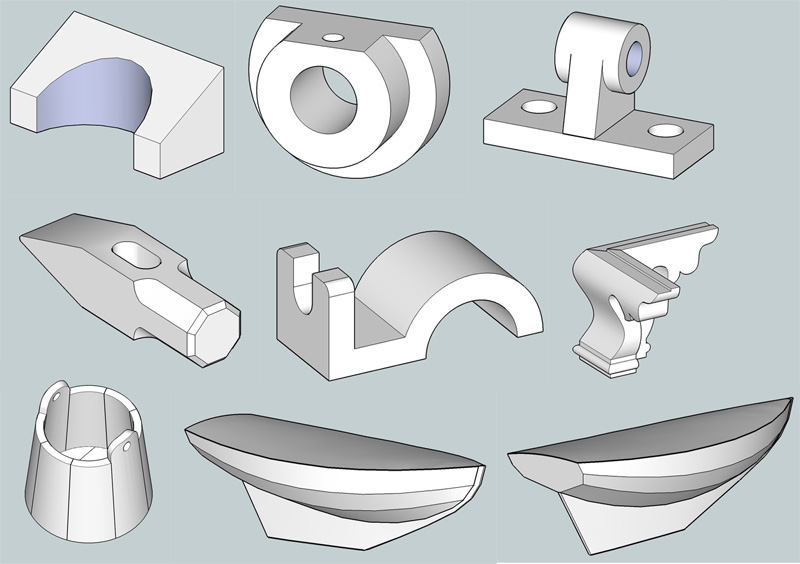
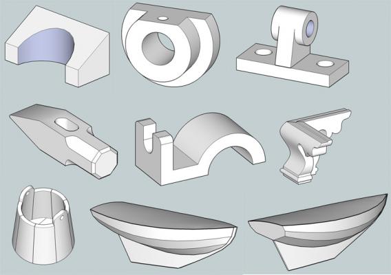
I was on a drafting table for about 6 years as a die designer in the forging industry then switched over to a 2D program called ANVIL 1000; it's still around but a little pricy. Then we migrated to SolidWorks which I prefer to use. Each one of these programs has a learning curve but it is easier to grasp the fundamentals and get up to a production level if you have previous drawing board experience. (IMHO) I found the best way to learn SketchUp was to start modeling some of my old high school vocational projects . Simple geometric shapes at first then gradually working into something more advanced. Even if you're just going to trace over an existing design, it still helps to have a good knowledge of the basic tools and what you can do with them under your belt. If you start out with "lofty" ideas (no pun intended), your CAD program could end up in the closet along with your model ship. Like anything else it takes practice, practice, practice. Some examples of SketchUp work I have done in addition to what I have posted already. -----added---- If you're looking for a good SketchUp learning source I found the tutorials at the Chiefwoodworkers Blog to be excellent http://www.srww.com/blog/
-
Copper wire that you get from the craft stores has a kind of film on it which keeps it shinny and prevents patina, this is probably why the sculpey doesn't want to stick. Try using a piece of emery cloth to strip the wire and rough up the wire surface.
-
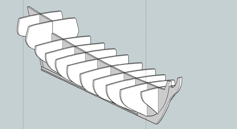
I have seen some pretty amazing work done in SketchUp which is a free program. I have worked with it myself to produce these images. Admittedly these are very rough and more of a "proof" of concept but if you do a search on the forum I'm sure you can find the post. ----- here's a link http://modelshipworld.com/index.php?/topic/844-hms-pandora-1779-cad-build-log/

-
The videos of the sailors walking is amazing but it doesn't look natural. I think the problem I noticed and this is just a observation is the hips appear to be stationary. When we walk and place our right or left foot in front of us our hip for that particular leg drops accordingly. I have no idea if that motion is possible to animate or how difficult it might be to do. Still, it's pretty amazing.
-
Check this out http://grabcad.com/requests/how-to-get-command-window-displayed-in-draftsight
-
Thanks for posting your SW views Alan, nice work. I like the copper tone as well and I may give that a try. I found the spherical zebra option a better choice but I am going to use the traditional waterline approach to fair my hull. I also like the idea of using a plank thickness as a tolerance.
-
This is an amazing project, thanks for posting the link.
-
Draftsight Question
Don9of11 replied to alde's topic in CAD and 3D Modelling/Drafting Plans with Software
I recently upgrade from WinXP to Win7. I then downloaded the most current free version of Draftsight and my cursor was so sluggish, I gave up on the program. I have all the latest video drivers for my video card and monitor; I'm running dual core and 4gb ram. I can't seem to figure out what is wrong. My copy of SW2004 run just fine on Win7, I was concerned that it wouldn't and Sketchup is working quite well too. Draftsight isn't though. -
HMB Endeavour 1768 3D Model
Don9of11 replied to ODemuth's topic in CAD and 3D Modelling/Drafting Plans with Software
Your attention to detail has payed off. Nice work! Have you been keeping track of your time? How long did it take you to get to this stage of development? -
Making sense of Zebra View in SolidWorks
Don9of11 replied to AON's topic in CAD and 3D Modelling/Drafting Plans with Software
Here is an example of a Bounty class launch that has a perfectly shaped elliptical hull. In the real world you would never see this, at least I don't think you would. I would think you would see symmetry on the view of the bottom hull but that must depend on the position of the cube and the mirrored surface of the boat. The lines do flow all together so this hull is smooth. I think this could be a good visual tool to easily see bad spots in a hull but ultimately its going to be the traditional measurement of waterlines, buttock lines, etc. that determine the fairness of the hull.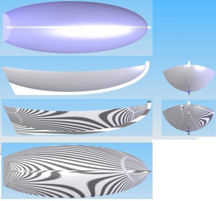
- 9 replies
-
- 3
-

-
- CAD
- SolidWorks
- (and 2 more)
-
Making sense of Zebra View in SolidWorks
Don9of11 replied to AON's topic in CAD and 3D Modelling/Drafting Plans with Software
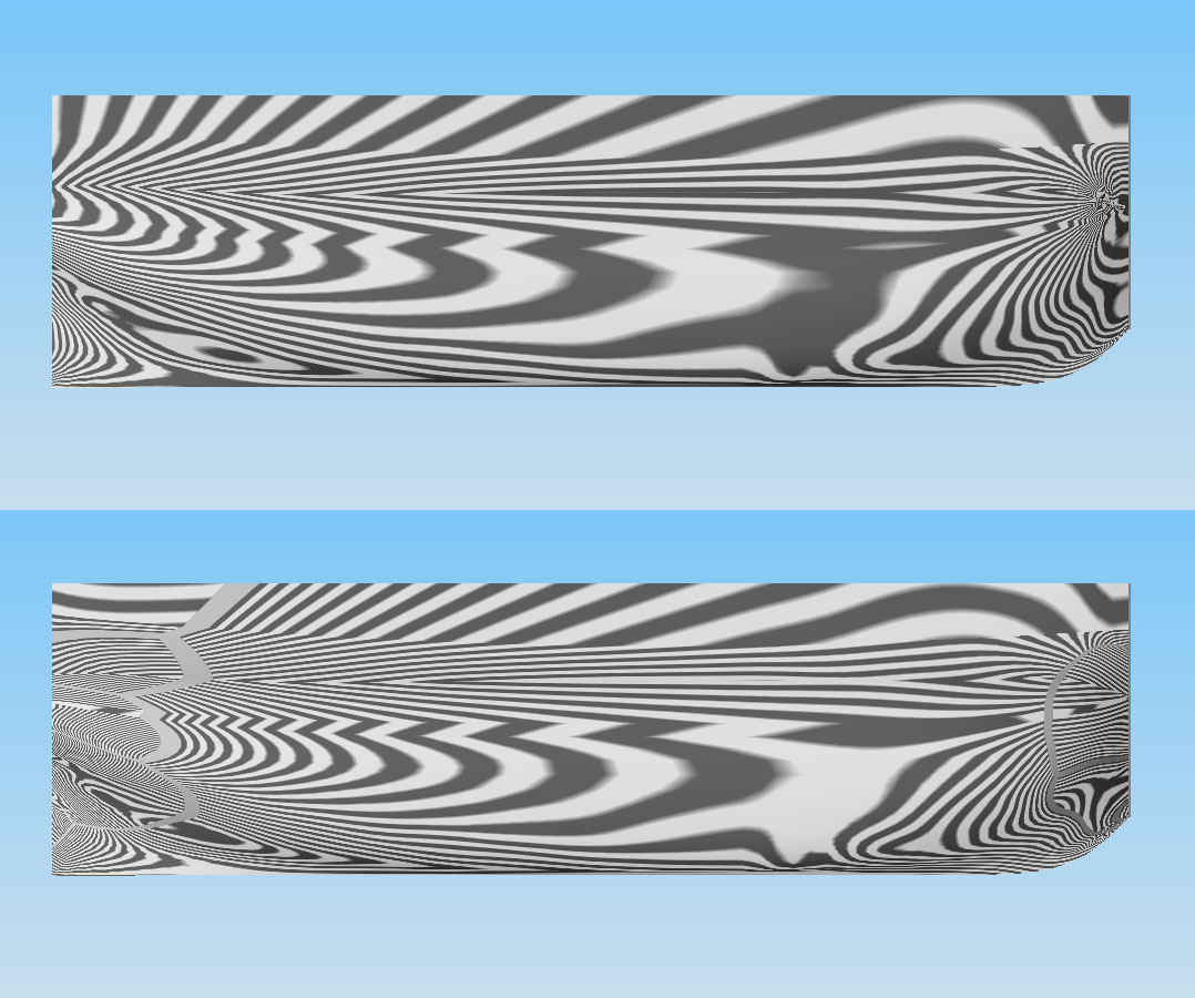
If I understand Zebra lines, they represent the smoothness of a surface. In the top view, my ship the lines are all contiguous until you get to the dead flat and just forward of that the zebra line gets smudged out. The same is true for the bottom view. This indicates there is a problem, a dent or some other deviation. The same thing can be seen in the aft part of the ship near the keel and other areas if you pay close attention. Wherever the zebra lines break or fail to merge together smoothly there is some kind of deviation in the hull and in fact by measuring various points along the waterlines (not shown here) I do indeed have issues with the frames just forward of the dead flat and probably in other areas as well. As with anything you see for the first time, its difficult to determine the significance of the zebra lines without a comparison to a goodly faired hull. If one could scan the hull of a real ship or even an admiralty model we might be surprised at the results. For all I know the pattern of these lines might be acceptable at the scales we build our ships.- 9 replies
-
- 1
-
-
- CAD
- SolidWorks
- (and 2 more)
-
Making sense of Zebra View in SolidWorks
Don9of11 replied to AON's topic in CAD and 3D Modelling/Drafting Plans with Software
Alan it turns out I do have Zebra line feature. Here is an image of my ship lines The top view is with the spherical option and the bottom view is with the cube option. It is very confusing to look at and I haven't figured out exactly what its showing me.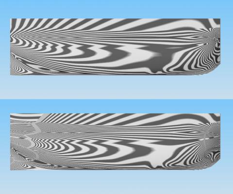
-
Making sense of Zebra View in SolidWorks
Don9of11 replied to AON's topic in CAD and 3D Modelling/Drafting Plans with Software
Hey Alan, I think from watching this short video http://www.youtube.com/watch?v=32E_iLzXeJk the zebra stripes should all line up, there shouldn't be any breaks in them. If it were me, I would visit the SW forums and ask those folks what the lines mean in the context of a ship hull. Something else I found that might be helpful http://blog.capinc.com/2011/06/solidworks-tech-tip-how-smooth-is-smooth/ The shape of the hull is complex and double curved (ie spherical) in nature, especially at the bow. You might want to experiment by making a ellipsoid or other football shape where you know the lines are true and study the zebra effect on those instead of using rectangles and cylinders. (IMHO) I'm going to look back through my SW 2004, I saw some references on the SW forums that indicate my version might have the Zebra feature. -
I have gotten small wire at Pat Catans or Michaels. I have sizes ranging from 18 gauge (.04 diameter) down to 34 gauge (.006 diameter), both brass and steel. I imagine Hobby Lobby has stuff like that too.
-
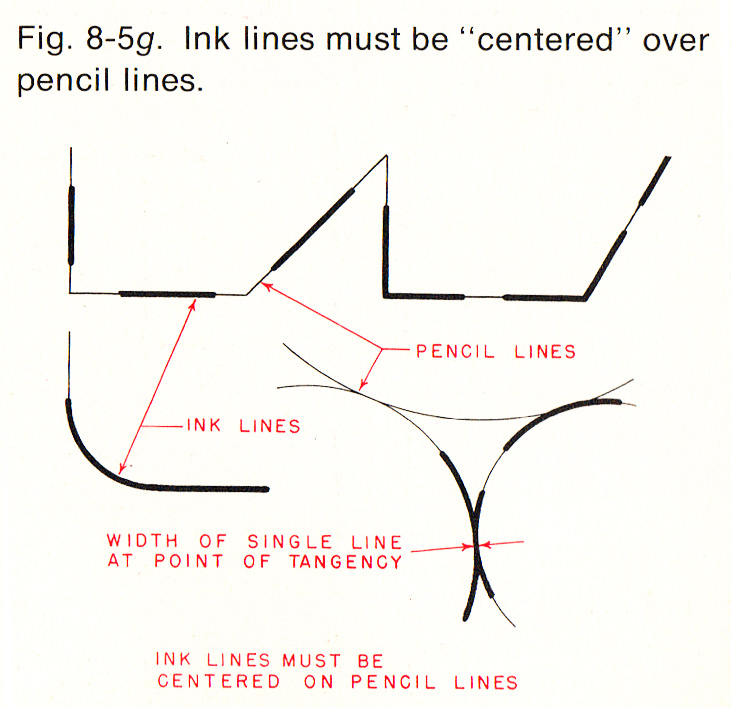
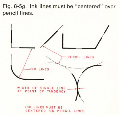
If you decide to scale the drawing using some scanning/enlarging method and the lines get thicker just work to the center of the line. My reasoning is that years ago drawings were drawn in pencil, very lightly and then draftsman would "ink" over the lines. The pencil line acted like a center line and measurements were taken from the center of the line to the center of the next line, never to the outside or inside. This reasoning can be applied to lines that get bigger by enlarging.
-
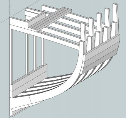
Solidworks framing help (please)
Don9of11 replied to AON's topic in CAD and 3D Modelling/Drafting Plans with Software
I think since the thickness of each frame will be different you will need to lay off each frame to create the loft. Perhaps use an offset from the hull line? -
I did something similar to what druxey suggested except that I used my inkjet printer to print the ship name on decal paper. Using my word program I selected a font and letter size that fit exactly.