

Don9of11
-
Posts
718 -
Joined
-
Last visited
Content Type
Profiles
Forums
Gallery
Events
Posts posted by Don9of11
-
-
Ed,
I wasn't aware of that book, but thanks for letting me know. It sounds like that is exactly the sort of information I should be using, but unfortunately I'm not able to get access to a copy.
Dida,
These are the add-ons I've used most frequently:
Curviloft (available here: http://rhin.crai.archi.fr/rld/plugin_details.php?id=674) is used to generate a smooth, curved surface.
Bezierspline (available here: http://rhin.crai.archi.fr/rld/plugin_details.php?id=34) is used to generate a number of different types of spline curves.
Joint Push Pull (available here: http://rhin.crai.archi.fr/rld/plugin_details.php?id=719) is used to offset a curved surface by a defined distance (for example, adding in planking that is X inches thick).
SU2KT (available here: http://rhin.crai.archi.fr/rld/plugin_details.php?id=423) is used to export the Sketchup file for rendering with Kerkythea.
Thanks for the plugins. I downloaded the newest version of Sketchup and I am not able to install these I think because Sketchup is looking for rbz files and these are rb files. Has anyone else have trouble installing these scripts?
-
I have a build log here http://www.howefamily.com/zellars_progress_photos/zellars.asp with about 300 photos of my Constructo Enterprise model that might be of help to you.
If I recall I ran two strips full length on either side of the centerline of deck.
-
You could take one piece of 1/2 inch square material and glue two 1/8 inch sq. strips to it form the groove, that would leave you with a 1/8 inch groove for your glass. If you want a 1 inch post then you would need 3/8 inch strips and set them in 1/16 inch on each side that would also give you a 1/8 inch groove. If you don't want a reveal or you don't want to see two strips glued together just face it off with the appropriate sized plank. - no power tools required.
- alexmd and Doreltomin
-
 2
2
-
If you have an office supply store near by check out the packing tape supplies to get anything bigger than 1 inch; there are some low tack - not so sticky packing tape that pulls off very easily or look around in the painters area of the hardware store.
-
I was doing some research and came across this website. You can upload your model, and this company will make it on a 3D printer for you. They can print in different materials like Brass, steel, aluminum, ceramics, plastics. I haven't explored the whole site but it looks pretty interesting.
-
So, I have been experimenting with SW2004 and tried to scale my sketch. I started with a scale of 1:48. SW gives me two ways the scale up. One is to scale the sketch itself. This method caused SW to through a hissy fit with a nasty little note:
gun deck: Warning: The sketch has not been updated because solving it would result in invalid geometry (such as a zero-length line). Consider :
o Deleting the invalid geometry.
o Changing relations or dimensions to eliminate the invalid geometry.Despite this, SW actually produced an arc that measures 21793.59906027 inches. My experience though has taught me that when SW is unhappy it's best to find another solution.
The other method involves scaling the part, I went back to my original sketch and did a mid-plane surface extrude of 1/16 inch, then I went to the Feature Manager and did a Scale. SW didn't complain about this method. So it would seem I am home free - not.
Both methods have draw backs, as the scaled entity or part can't be used for anything other than for reference; in other words you can't build upon it or set up any relations to it. I think this is because even though the radius was scaled up it is still larger than the 1640ft envelope.
I think drawing a arc at 1:48 or even 1/2 scale would allow me to go in and get some very accurate measurements at different stations that I can then carry over to my full size and lay off a spline.
-
Thanks everyone, I ended up plotting a few more points and used a spline. But I am going to try the suggestion of a smaller radius and scale it up and see what happens.
-
I recently was drawing my 74 gun ship full size in Solidworks (SW2004) and ran into a limitation when I went to lay off the gun deck. It's an arc running through 3 points, set at the aft perpendicular (294in above rabbet of keel), dead-flat (270in above rabbet keel) and forward perpendicular (294in) across a span of (2112in; 176ft between perpendiculars).
I researched it a little and found that SW has a 500m (1640ft) envelope, the radius I needed to draw exceeds this. I tried splitting up the radius into 2 segments but the aft arc still exceeds this envelope. I can add a spline but the spline dips below the horizontal by a small margin aft of the dead-flat, so I think I need to calculate a few more points. Anyway. I wanted to mention this as a possible work around and wondered if anyone has run into other limitations in there CAD programs.
-
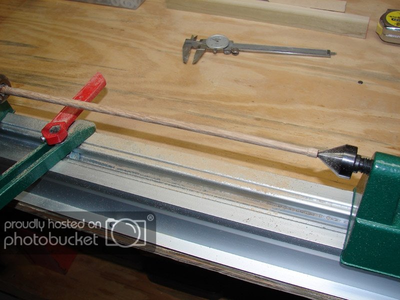
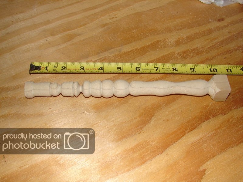
I realize I'm late on this thread but might I suggest the Grizzly hobby lathe. http://www.grizzly.com/products/Hobby-Lathe-Disc-Sander/H2669
I have one and it's not a bad investment for the money and it does a descent job. It's 24 inches between centers and adjustable speeds. I have used for turning the mast's for my Enterprise and I have used for some other turning projects.
-
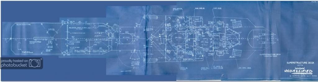
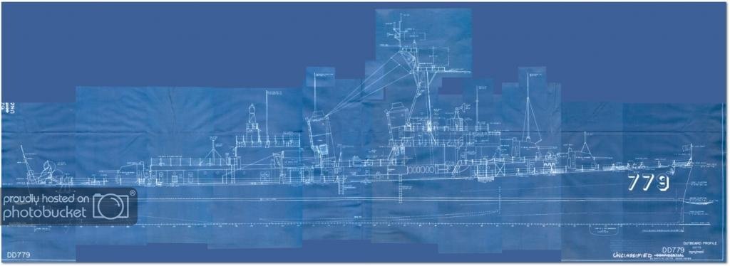
I've had a little experience with this type of problem when I got plans for the USS Douglas Fox, DD-779 which I used to help build my Zellar's project. I took photographs myself from the original Booklet of General Plans which had been folded up in a cabinet drawer for who knows how long, so there were serious folds and bends to contend with. I used photoshop to stitch everything together, I set up the distance between perpendiculars, frames and other ship particulars as best I could using guide lines. Even though we talking about different ships the process would be similar. Once I did that step for all the photos and different parts of the ship I sliced the images into smaller chunks to import them into my CAD program. Once I got them in the CAD program and despite all the work I put in to fair up everything, there were still areas where I had to make a decision about how the lines went. I prefer to try an fair the photos, scans or drawings in photoshop as opposed to doing it in the CAD program. I attached a few photos so you can see what I was dealing with. Hope this helps.
-
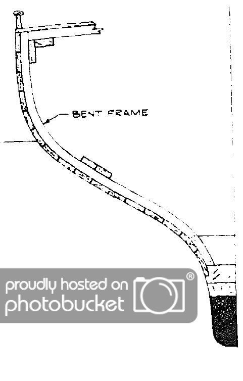
If you create a plane at the cross section of each frame then you can sketch each individual plank along the frame; it would look like a bunch of little rectangles along a curve as in this sketch below. Do this at each frame; then when you're done come back and connect all the points with a spline. It's a lot of work but I can't think of a more accurate way of doing it. I'm interested in seeing how WackoWolf does it maybe he has a better way!
-
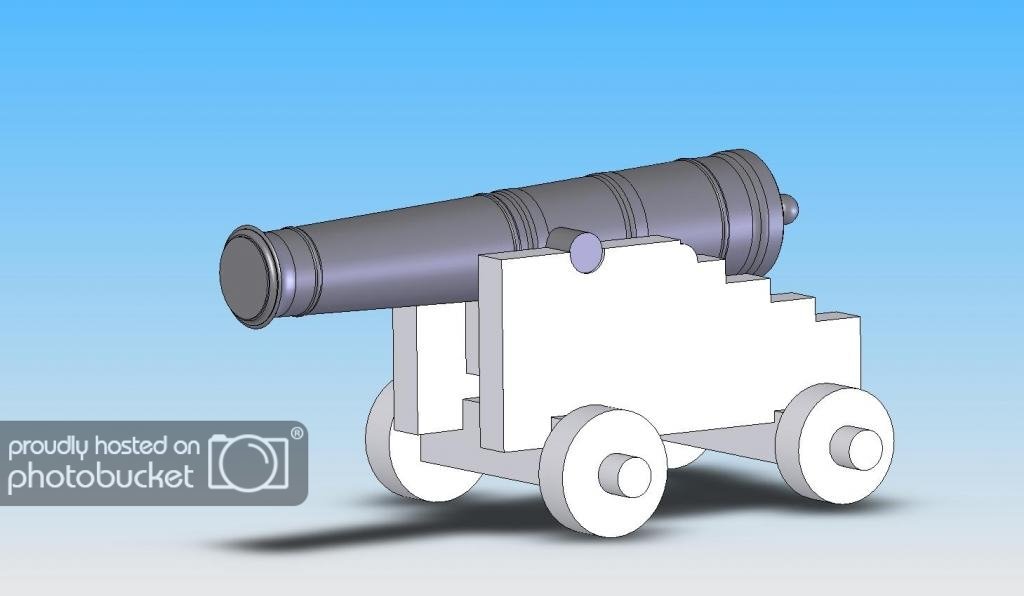
Thanks Krutzelpuntz a 3D printer would be sweet; I made the model to produce plans for the gun carriage. You'll find some instruction for the gun carriage in the Treatise of Artillery as well. Before you decide to make your own gun carriages do a little home work and determine what time period your ship was built in. Gun carriages are not all alike and many differences exist in there construction. This is especially true of English and French gun makers.
-
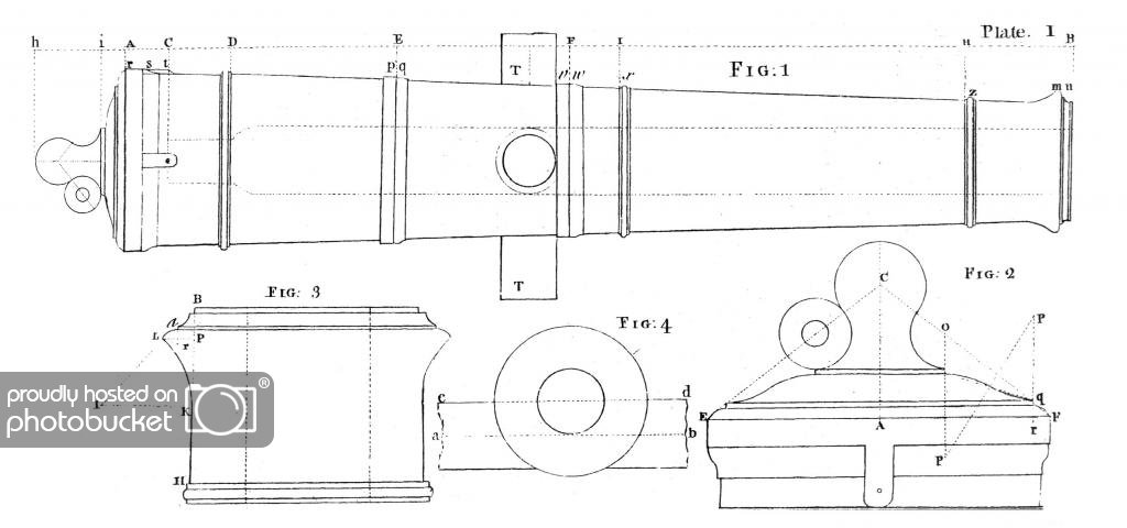
I found that the work of John Muller's "A Treatise of Artillery" to be a very good source for the dimensions and caliber of ship guns as well as those on land. It's available for download through Google http://books.google.com/books/about/A_Treatise_of_Artillery.html?id=vylEAAAAYAAJ but be forewarned that Google is famous for bad scans. I ordered my copy through Amazon. Anyway, every detail is described such as the wall thickness, materials, and gun carriages; so I think you and others will find it a good reference. This is just a sample page. If anyone needs additional information I'd be happy to do some look ups.
I did a 3D model of a 6 lb cannon for my Enterprise model thought I would post it to.
- Krutzelpuntz and WackoWolf
-
2
-
nrg710, the waviness in the surface is caused by the irregularities in your cross-sections. In the photo you posted showing the front view, I can see that the sections don't form smooth curves, so you need to do a little work with those to smooth them out. Also, make sure that the sections run along a "fair" curve from one end of the keel to the other. I call these "guide curves" and if the guide curves are smooth and fair that is with no dips or high spots then your hull will form more nicely. Otherwise you work looks very good.
WackWolf, awesome work on your model. How many guns on this ship your building.
-
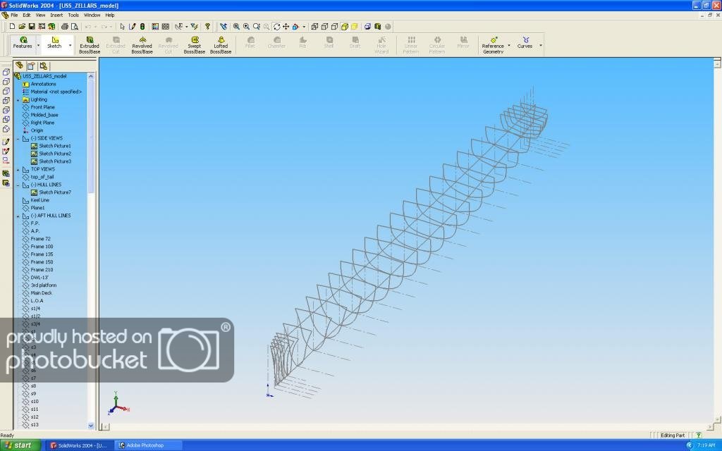
I have had some experience in this area but I have SW 2004 so I may not be able to help you. I used SW to develop the hull of the USS Zellars DD-777. One of the problems I ran into was a zero thickness issue at the bow and stern areas because I was trying to form the hull using all the sections and SW kept barking at me about zero thicknesses. I ended up loftng the bow and stern separately. If you can post a couple photos maybe I can give some suggestions or PM me with more particulars.

-
There are a couple free programs, one is Draftsight which is 2D only; the other is a product called FreeCad.
I have used Draftsight before - if all you want to do is trace over the original and fair things up it's great drafting program for free.
FreeCad is something I just recently came across and I haven't tried it yet.
-
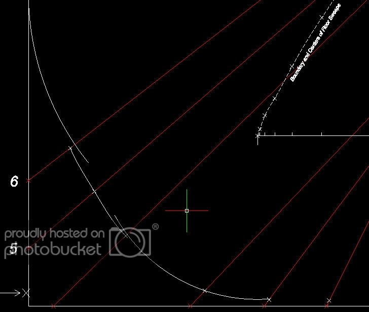
DraftSight does have limitations as I discovered last week. I was trying to use a spline to create a reconciling sweep for the lower body of the ship. I wanted to run a spline through three points and then make the spline tangent to those sweeps at each end. DraftSight can't do that. The other issue I ran across is when a point is created and when it is at the intersection of two lines. The created point is recognized as an end point, a point at the intersection of two lines is recognized as a node and if you want to draw a circle from the center of a floor sweep through a point at the intersection of two lines DrafSight won't do it. I may take another look at it tomorrow to see if there is another way. It's a little disappointing as I was making good progress.
-
Speaking of Drafsight, I'm having trouble with splines. The spline passes through the first and last points but only passes through some of the points in between. I can't figure out what I am doing wrong.
Maybe this needs to be it's own thread?
-
WackoWolf,
I had prior CAD experience before learning SolidWorks. I was using Anvil 1000 which is like Draftsight except for the command line thingy, so my learning curve to get up to a production level wasn't very long. I think SW is the perfect tool for modeling. I'm between jobs at the moment and decided to learn Draftsight, figured it wouldn't hurt to have another CAD program on my resume.
-
I downloaded and started using DraftSight this week. It took me a few days to get up to a production level and still learning things as I go. I really don't care for the command line interface otherwise it seems very robust. What I haven't figured out is how to take something full size and print it out to a 1/4 scale or 1/8 scale. I'm also a SolidWorks 2004 user and I would like to have a newer version but darn if it isn't pricey.
As for AVG and Norton, I would dump them both and switch over to Microsoft Security Essentials. I used AVG, McAfee and Norton in the past and just got tired of having to pay for the darn things. With MSE, I have never had any problems with viruses or malware. You might want to check it out and it's free!
-
I started learning Solidworks when it first came out back in 97 when I was a forging die designer and I found it to be very easy to learn and use. That said, I also had several years of board experience and several years of using a 2d CAD program called Anvil 1000. I still use SW 2004 and wish I could get a more recent version.
Lofting a ships hull is a rather "lofty" and ambitious goal for someone just starting out, but with perseverence and paitence I'm sure you'll succeed. However, you might want to take a step back and learn some basic concepts on how to use SW. I learned by taking out some of my old vocational drafting projects I did in high school and worked with it evey day until I got the basics under my belt. Within a couple to 3 weeks I was pretty much back to my previous produciton level using 2d CAD.
If you need any help just ask, I'm sure I can help you.

-
I used to think the people on MSW were a credible and respectable bunch. You don't really buy into this nonsense stuff do you? Next you'll be telling me that aliens help build the Nina, Pinta and Santa Maria!

-
I'm very impressed with the details of this model.
-
I have done something similar but I always used a glue stick the kind you would find at Staples or Office Max http://www.staples.com/Staples-Washable-Glue-Sticks/product_SS992770 The residue is minimal if any that a light sanding wouldn't take care of.
I'll have to try the freezer paper and see how it works.
USS Basilone DD-824 by schooner - FINISHED - BlueJacket Shipcrafters - Scale 1:192 - from USS Gearing kit
in - Kit build logs for subjects built from 1901 - Present Day
Posted
Nice looking build. I built a Sumner class destroyer from scratch. http://www.howefamily.com/zellars_progress_photos/zellars.asp