

Don9of11
-
Posts
718 -
Joined
-
Last visited
Content Type
Profiles
Forums
Gallery
Events
Posts posted by Don9of11
-
-
I think it looks good Alan.
I was looking this over and maybe you have thought about this yourself but here's a suggestion, I was thinking it might be easier to loft the section from the last frame to the blue line then loft the lower section of the stern. Of course that would leave you with a sharp edge which then all you need to do is add a corner radius.
I am learning not to spend to much time making it perfect the first time because in the end you need to check it with the diagonal lines and buttock lines as druxey suggest and the lines on the drawing while necessary to start, will not be the lines you actually end up with.
-
I'm still following your work Alan with great interest. I like the photos you reference from the Bellona build, I hadn't seen those. I'm just getting up myself and will read through what you have done and maybe offer some suggestions. So far as I can see your SW skills are very good, don't give up.
-
I know that my transom lines are not correct. I took my inspiration from Goodwin's, English Man of War pg. 24, top left illustration which shows the disposition of the cant frames. Also, I've been following and studying the HMS Bellona by SJSoane - Scale 1:64, 1760 English 74 gun, as designed, build log and paying special attention to the NMM model of the Bellona and the early stages of the SJSoane's own model where the transom pieces are added.
The transom and fashion pieces all curve inward to meet last frame and as Druxey pointed out the contours change rapidly. I simply drew a curve at my water-lines and connected the dots so-to-speak. I made no attempt to do it accurately but simply to illustrate. If you look at the stern view, the corner you refer to I think is going to naturally develop and as Hexnut suggest a variable round will be needed after everything is knitted together.
It took me about half-an-hour to produce the stern surface, no lie

- Elmer Cornish and hexnut
-
 2
2
-
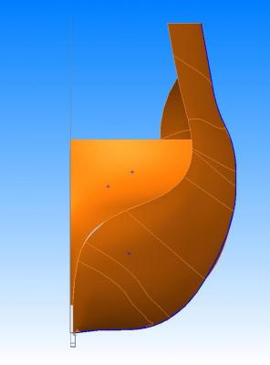
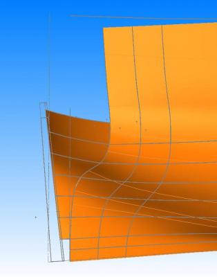
Alan, I've been giving some thought to your work and not to through a monkey-wrench into your thought process but consider my hasty attempt to produce the stern of my ship. I have produced three images which I hope illustrate my idea.
Consider how the transoms are shaped as they come up the stern post and using water-lines connect them. In my images I actually went above the wing transom, stop short of the keel and carried my imaginary transoms to the middle line vs. ending right on the stern post. I know the transoms don't go that far down but I did this to illustrate my idea. I used frame 36 as a guide curve and I have a little gap in my surface-lofts.
Is this not what you're trying to achieve?

-
A model shipwright a kit does not make~
This is nice kit and the build logs are awesome but no matter how well the pieces are cut or how nice the kit looks in photos, until they make there way into the hands of the shipwright that's all they are is cut pieces.
You mentioned throwing out what you've started, did you begin a HMS Alert build log? I didn't see a link.
-

You're farther along than I am Alan but I given this some thought and here is what I come up with, forgive the crudeness of my sketches :
A) lower left, draw in phantom stations (red) after frame 36 making sure they follow the wing and deck transoms and tie everything together at the keel with guide curves, then trim away what you don't need
A1) upper right, draw in the counter timbers, wing and deck transoms and then "flesh" it out from there.
After the last frame, the ship is basically open and now you're trying to "cap" it and I think you're going to need the counter timbers and transom geometries to do this or perhaps a combination of both ideas.
-
-
Nice work Alan! The development of the stern area makes the bow look easy

-
She's coming along Alan, and she's looking good. Your lofting of the bow looks great and I'll be paying close attention to your stern progress.
-
TFFM? I dislike acronyms.
It doesn't surprise me that the yard would build ships per experience and material available but they couldn't be to far off the mark as there were penalties to pay. I'm following your post very closely, so if you make a mistake, I'm blaming you...LOL.
-
Well you could try Model Expo's Sultana. It's the same scale as your Scotland (if you have the ME's version that is ) and it's a solid hull, so there's no need to worry about bulk heads and hull planking. It will require some sanding & shaping of the hull using templates and then adding the deck fittings and rigging. It's about 1/2 the cost of your Scotland. Sometimes ME runs this kit on sale and you can get for a lot less. You could also check out BlueJacket Shipcrafters "Skiff" kit. It's about as basic as you can get and under $40.
I know what your going through, my first build was Constructo's Enterprise kit. Having a background building model cars and airplanes the Enterprise was just daunting. It took perseverance, patience, a lot of reading and help from forum members. When I look back at my Enterprise, I see so many things I should have done and now can do better. I'm really proud of that ship and every night I look at it and realize how far I have come.
The ship you have is intimidating for a first timer but if you take your time, do some reading and ask for help, I think you could do it. Each ship that is built is unique and has it's own character that you build into it. Don't worry about being perfect the first time.
-
Your skill level is amazing, I asked about the officer because I have been looking for 2d officer for some Sketchup work I was doing.
-
-
Part 6: Getting ready to form the hull
After a bit of a delay, I'm back.
Back on page 2 (and almost a year ago!), the stations were defined. The stern needs to be defined, and the bow and topsides still need a little work before the surface can be skinned. These will be the subjects of today's post.
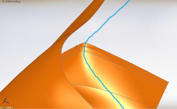
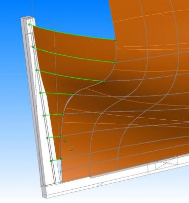
The edges of the transom, counter, and stern timbers were drawn in by tracing these timbers from both the body and sheer plans (purple lines) and projecting to an intersection, as shown below. The final edge is highlighted in red. The aft edge of the wing transom (green line) was traced from the framing plan, and the blue line follows the rabbet on the sternpost. Note that the last few stations have been hidden for clarity.
Next, lines were drawn in to define both the lower and upper edges of the hull's shape. The lower edge is simplest, as it merely connects the bottom ends of the station lines. Forward of the foremost station, this line continues up the stem, so that it defines the profile of the hull as seen on the sheer plan. Later, this line will be used to form the rabbet. The point at which this line terminates is taken from the sheer plan. Only the forward portion is shown below, but this line (blue) continues all the way aft.
Most of the upper edge was drawn in using the same method of connecting station to station and tracing from the sheer plan when needed (for example, at the scrolls). Finally, a curve was drawn in to connect the first few stations and the forward line described above. For this, I tried a number of different splines and curves included in the BezierSpline plugin until I found one that looked reasonable.
The end result of all of this was the construction of a number of closed loops that together will make up the surface of the hull. The next post will discuss how to create this surface.
Sketchup, when you created the stem, keel and stern post, did you incorporate any taper or did you make the same width? I look forward to seeing how you run the rabbet and your hull surface.
-
Amazing work Magnus. When I watch the character walk from the front or rear and I pay attention to his feet the camera (floor) seems to be moving left and right. When I watch from the side at his feet it looks like he is walking on a tread mill. The only other observation I would make are the hands, he looks like he is ready to draw a gun. You may have mentioned this before but where did you get the measurements for the uniform? Are you just using photos and existing paintings?
-
-
If you're only looking to turn spars, mast, etc, I would check out the Grizzly Hobby Lathe.
http://www.grizzly.com/products/Hobby-Lathe-Disc-Sander/H2669
I have one and it's come in handy for turning mast and spars and other small turning projects. It's easy to setup and use all need is the drill motor that fits the collar. You can attach it to your work bench with some clamps or mount it directly. I used it to turn the mast for my Enterprise.


- Q A's Revenge, Tigerdvr, AON and 3 others
-
6
-
You could try SketchUp, it's free and not to difficult to learn.
-
Your decision to measure the drawings surprises me; still it's interesting to see the differences from one plan to the other.
-
Your work is awesome! To have completed what you have done so far is amazing. Are you switching CAD programs or staying with Sketchup? I wouldn't worry too much about having to start over, it's the mark of a good shipwright and what you have learned so far will aid you in your new efforts.
-
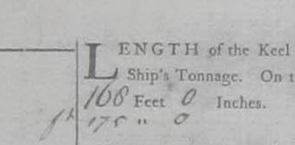
Alan, I'm curious about a note in the upper left corner of the contract next to the first paragraph on page one and a note similar to this with the date of 1805 in the left-hand column several pages later next to the paragraphs Time of Launching. This is just speculation on my part but I wonder if the Bellerophon underwent a refit after the Battle of Trafalgar and these penned scantlings are from that period?
-
If you look closely next to the scantlings that have been changed or in some cases above the scantling, you will find there are initials. This means that the changes were agreed to, whether before or after the ship was built or if this was a common practice to mark the contract up in this manner, I can't determine.
- daHeld73 and Elmer Cornish
-
2
-
Alan, why don't you start a separate configuration using the penned in dimensions, I've done that with the 74 I am working on. I put Steel's dimensions in a configuration all it's own within the same model that way I can refer to it when ever I want. Starting over has it's benefits too as it will test what you learned so far.
-
Has anyone of you tried Blender? It is on the same level as any other 3D Software and it is free. It is based (as Linux) on people that are developing it. I work with Blender and many people are using it as professional software.
I tried Blender a few years back and I found it difficult to use. Blender like 3DS Max is an artistic program verses a mechanical drafting program (IMHO) I have seen a lot of cool stuff created with Blender and like any program you have to stick with it in order to learn it.
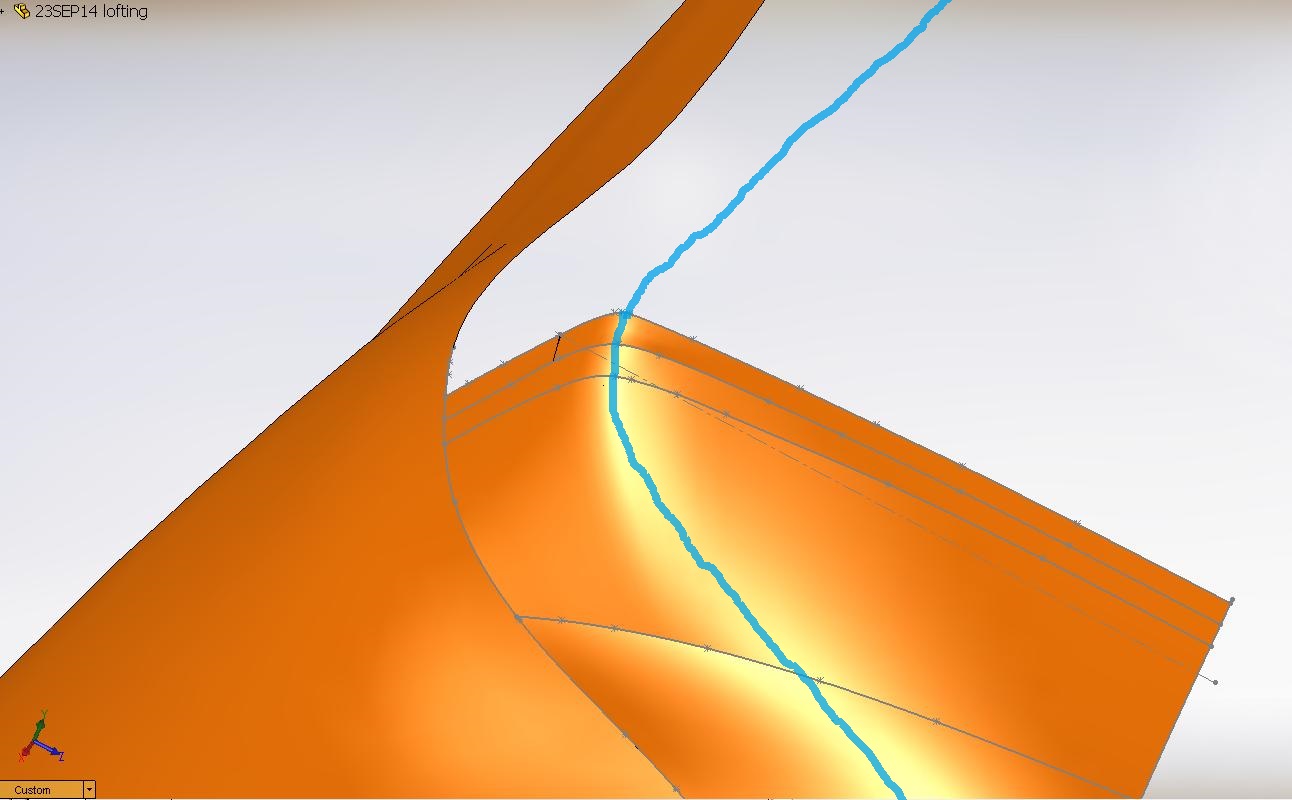


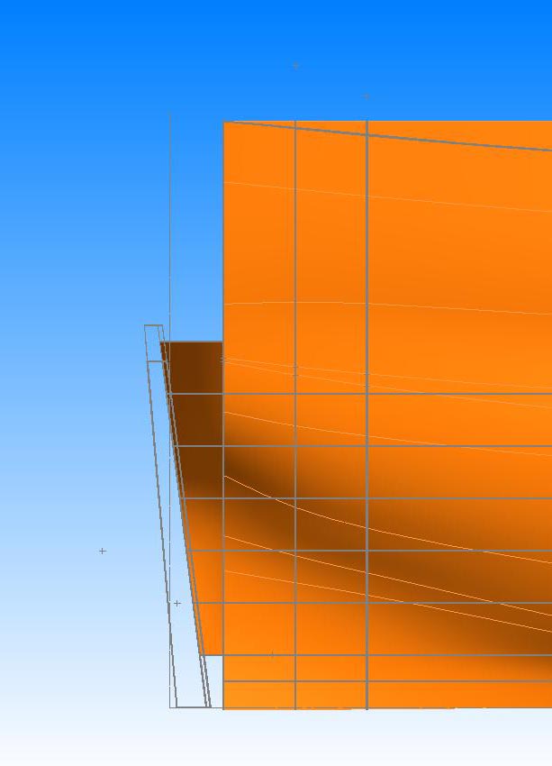

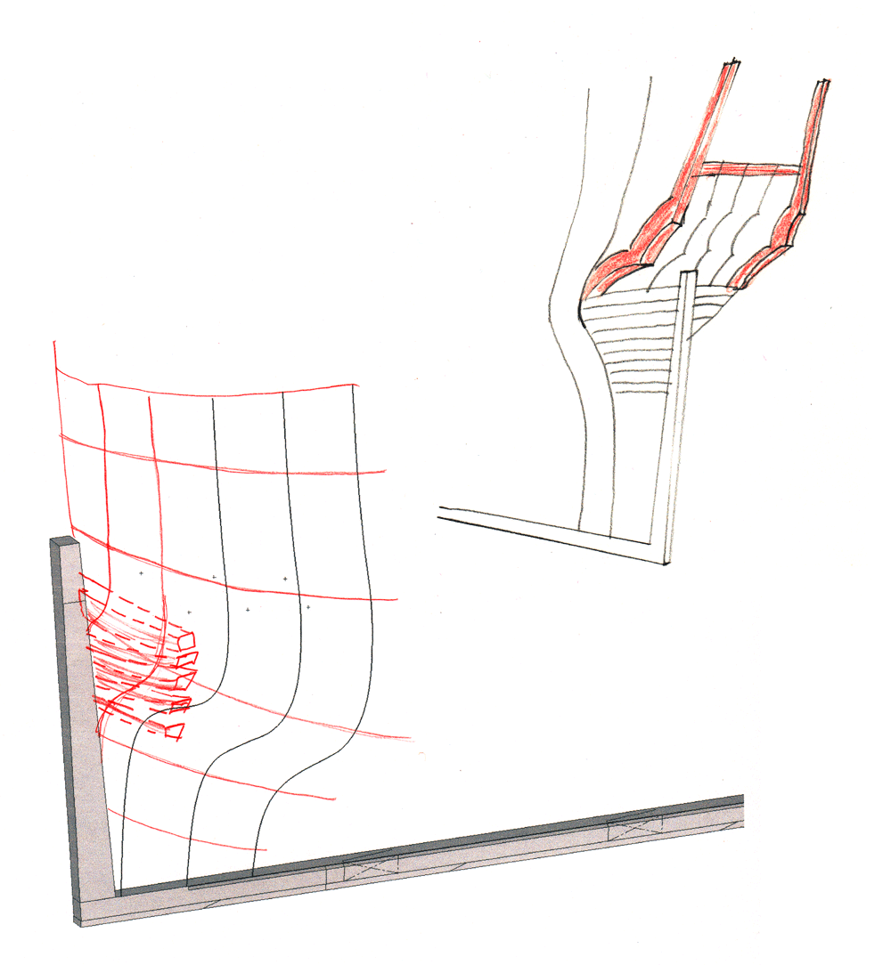


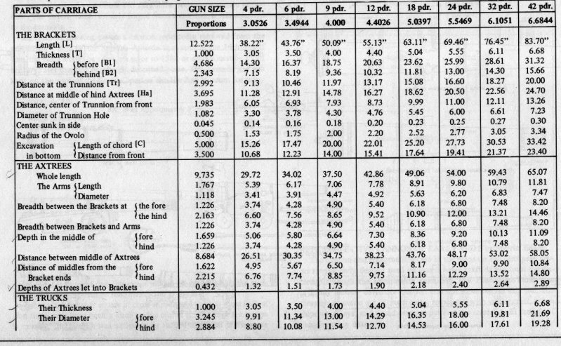
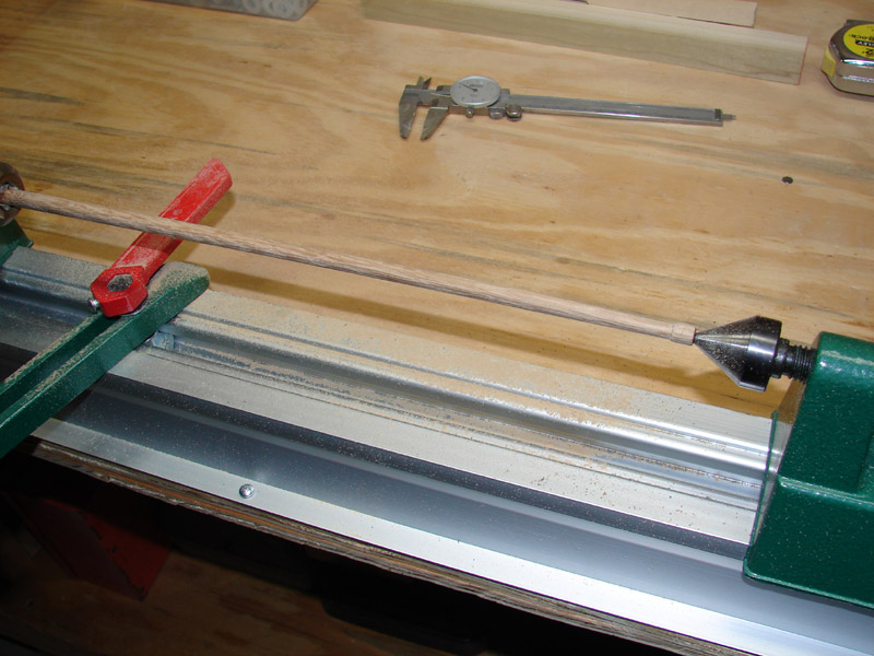

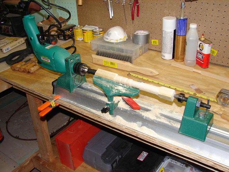
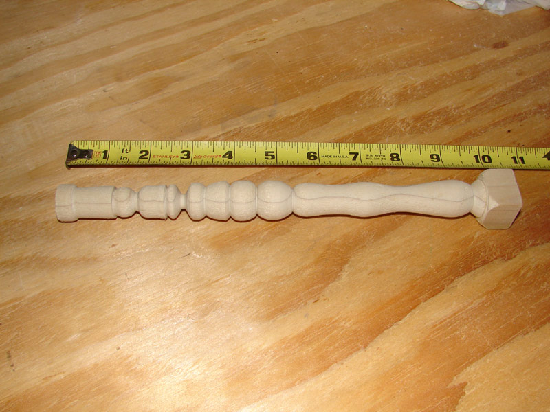
Table Saw Hand Safety
in Modeling tools and Workshop Equipment
Posted
A piece of safety equipment that I haven't seen mentioned is "hearing protection"; Table saws and similar machines are very noisy and can damage your hearing over time. Safety glasses whether they are goggles, side shields or prescription safety glasses are also very important.