

Don9of11
-
Posts
718 -
Joined
-
Last visited
Reputation Activity
-

 Don9of11 reacted to SJSoane in HMS Bellona 1760 by SJSoane - Scale 1:64 - English 74-gun - as designed
Thanks, Michael, I originally built it upside down Hahn-style, and so saw it this way for many years. It always looked like a good inspiration for a furniture design of some kind. or maybe a sculpture.
Well, I spent the entire day starting planking the lower counter, and got two parts not yet installed. But I learned a lot. Those of you who have done this before, did you pin these before gluing? I don't see how to clamp these for gluing, and wonder if pre-pinning will help keep everything in place.
Also, I abandoned Goodwin's note that these are 8" width. I tried ruling that out and it looked like way too many small pieces. I went from 12 to 9 strakes, and it looks more convincing. I am closer now to 10 inches at the broadest widths.
Mark
-
Don9of11 reacted to SJSoane in HMS Bellona 1760 by SJSoane - Scale 1:64 - English 74-gun - as designed
Hi everyone,
I haven't seen the Bellona upside down for several years; kind of scary unbolting it from the building board! In all the years of studying, drawing and visualizing the stern, I confess I did not fully appreciate how much the lower counter forms a horizontal shelf. I wonder how many ships boys found a nice place for a nap in the little cubby between the lower counter and the upper deck.
I am fairing the lower counter, and hoping to start planking it tomorrow. I'll re-read the great tutorials on planking on the website first...
Mark
-
Don9of11 reacted to SJSoane in HMS Bellona 1760 by SJSoane - Scale 1:64 - English 74-gun - as designed
Hi everyone,
Big event today. I started on the stern before Christmas, and today I finally glued everything except the upper and lower counter moldings and the two vertical counter timbers above the gun port cills. The moldings need profiles shaped before gluing, and the remaining counter timbers need a little more fitting. It is all looking shipshape!
Very, very slow progress on this. Good thing I am not doing this for money....
Best wishes,
Mark
-
Don9of11 reacted to SJSoane in HMS Bellona 1760 by SJSoane - Scale 1:64 - English 74-gun - as designed
Hi everyone,
So I finally figured out--I think--the intersection of the helm port transom and the stern post. After reviewing the photos of the original Bellona model very carefully, the helm port transom clearly intersects the stern post a little aft of center, with a bit of stern post both fore and aft of the helm port transom. So what kind of joint would suit this?
I considered a bridle joint intersecting the stern post. But I abandoned this idea, because this would weaken the post at the top by splitting it in two for the helm port transom to pass through. And I began to think that the continuity of the transom all the way across the stern for structural integrity was not necessary anyway. If the transom is split to save the integrity of the post, the two pieces of the transom still bridge on either side between two strong and stable anchoring points, the outer counter timber and the stern post. Furthermore, the upper deck transom (not shown yet in model or drawing) is only a little way above and aft of the helm port transom, and it bridges entirely across the stern giving all the transverse structural integrity needed here.
So accepting a split helm port transom, the joint to the stern post is either a dovetail or a mortise and tenon. Maybe I decided on the latter because I did not see how easily I would cut a dovetail in the top or the stern post at this late date. But I prefer to think I decided on the mortise and tenon because it would leave the stern post most structurally integral, and would provide no joint on top of the post for admitting water. This is my story and I am sticking with it....
The drawing shows the intersection without the lower chock for clarity, while the model shows the chocks in place, hiding the lower piece of the helm port transom on either side of the stern post.
Best wishes,
Mark
-
Don9of11 reacted to SJSoane in HMS Bellona 1760 by SJSoane - Scale 1:64 - English 74-gun - as designed
Hi everyone,
I continue to work on the stern, which proves to be the most complex thing I have ever built. Each piece interacts with several others, like a basket-weave. Nothing can be finally fixed, until others are fixed, which in turn depend on the first piece, etc. I discovered that even pinning things together doesn't entirely work, because the pieces move enough that fine fitting of another part is always off a bit.
So I decided to firm up the middle, with the rudder port chocks glued to the two adjacent vertical timbers, holding the center timber. With this as a foundation, the other parts can be fitted to something solid. That center piece was a bit tricky to shape, and I am showing a Sherline vise held by my bench vise, which allowed it to be held without breaking the open end.
I am also showing the helm port transom on the fore side of the timbers. Eventually, it will be cut in the middle, to come down to the top of the stern post. But I decided to keep it whole while fitting everything, to keep everything in alignment.
I keep thinking I am only a short time away from gluing it all up, but each little fitting of parts takes forever. Maybe next week....
Best wishes,
Mark
-
Don9of11 reacted to SJSoane in HMS Bellona 1760 by SJSoane - Scale 1:64 - English 74-gun - as designed
Hi everyone,
Quick update. I roughed in the helm port, which will be refined in size once I have a rudder to check against it. Getting this port shaped meant I could finally fit the center counter timber, which mortised into it. I don't know if this is the right joint here, but it made sense when I looked at it all. All pieces are now shaped and fitted. Time to cut the dovetails at the tops of the counter timbers, and fit the quarterdeck transom....
Mark
-
Don9of11 reacted to SJSoane in HMS Bellona 1760 by SJSoane - Scale 1:64 - English 74-gun - as designed
Hi everyone,
It is getting more interesting. I have attached a drawing based on the NMM photo of the 1760 Bellona model, highlighting where the transoms appear to be. It looks to me like the one I have labeled helm port transom does sit down on the vertical counter timbers, and then drops down to the side of the stern post. So it definitely is not on top of the post, or there would be no room for the tiller. But Gary is right that it is not aligned with the aft side of the stern post as I had originally drawn it. It appears to line up a little abaft of the rabbet in the stern post, which, if it is 10-12 inches thick, would put it right in the middle of the stern post. It either has a bridle joint, or the two halves tenon into the side of the post. Also note that the heads of the gun ports are a little lower than the helm port transom.
More difficult is that when I draw the helm port in this new more forward location on the stern post, the two sides are now too high to sit on the vertical counter timbers. I have got to keep playing with this in section, before everything lines up to look like the photo of the original model...
Best wishes,
Mar
-
Don9of11 reacted to garyshipwright in HMS Bellona 1760 by SJSoane - Scale 1:64 - English 74-gun - as designed
Hi Mark
Good drawing sir but I believe that the helm port transom would have intersected on the forward part of the stern post. Other then that sir I would say your drawing is right on. Not one of my better views of the stern Mark but should give you at least ideal's about how I approach this on my stern. Since these photo's, I didn't like my helm port transom and have taken it out. At the same time a few more items may come out and be replaced also. Guess items do have a way of coming back to haunt you untill you just have to change them out. Gary
-
Don9of11 reacted to SJSoane in HMS Bellona 1760 by SJSoane - Scale 1:64 - English 74-gun - as designed
Hi everyone,
Thanks, druxey, Gary and Ed. It is so helpful to have your expertise and critical eye looking at these reconstructions. This website supports the most remarkable community of learners. This shared detective work is almost as fun as the actual construction...
So, here is the latest reconstruction in light of recent insights from all of you.
The biggest change is information that there was likely no rabbet into a transom for the upper deck planking. To give the planking some landing, I have shown a "nailer" fayed to the fore side of the lower counter moulding. Some of the planks are going to run right into the fore side of the vertical timbers and vanish down to no thickness at the sternmost end, but it is what it is.
I have also shown chocks like the ones Ed shows in his book, because the lower counter planking will need something to land on at the edge of the rudder port. There may be chocks further down, but I can't visualize that yet.
And I am showing a rabbet where the helm port transom intersects with the top of the stern post. I don't know how I am going to cut that rabbet in the post at this point, but we'll see. Gary, do you think this is the way they likely intersected?
Thanks again for your outstanding help.
Best wishes,
Mark
-
Don9of11 reacted to SJSoane in HMS Bellona 1760 by SJSoane - Scale 1:64 - English 74-gun - as designed
Looking at the images of the Bellona stern again, I see that there is a square transom at the upper deck level, which has to be cut to leave room for the rudder head.
Looking at the images pointed out to me by druxey, there are a number of 74s with curved beams around the rudder head. So here is another interpretation, with a curved joining piece fayed to the fore side of the two halves of the square transom that I see in the Bellona photos.
I am also showing a smaller transom to serve as a landing for the decking just fore of the vertical pieces.
I'll try to build it....
Mark
-
Don9of11 reacted to SJSoane in HMS Bellona 1760 by SJSoane - Scale 1:64 - English 74-gun - as designed
I am working away on the stern construction, and realized that I did not yet understand how the helm port transom and the upper deck transoms fit. Here is a sketch of a possible reconstruction.
The helm port drops down to clear the helm, but it also means it runs into the side of the stern post. I had assumed that it would run clear entirely across the stern, but it clearly gets cut in half at the stern post.
And the upper deck transom has to accommodate both the hole for the rudder coming through, and also give a landing for the decking. It gets very broad...
I'll reflect on this and see if it still makes sense in the cold light of morning.
Mark
-
Don9of11 reacted to SJSoane in HMS Bellona 1760 by SJSoane - Scale 1:64 - English 74-gun - as designed
Hi everyone,
I have started construction on the stern. The first images show constructing the transom at the quarterdeck into which the vertical timbers will dovetail. When I taped it in place in the third image, I realized that there were too many parts in motion, and I would need a jig to keep it all aligned.
So the next images show a jig at the location of the stern lights. The most important thing to keep straight in this construction is the equal spacing of the stern lights. The jig represents the windows themselves, with the correct round up and round aft, and the locations of the vertical timbers. I then cut slots for the timbers into which I could locate them while shaping them. I did not have to work very hard to create the right bevel; I just filed the aft faces flush to the jig.
You will also see that I initially mounted the jig on a right angle fixture over a slab of granite. This allowed me to use a flat, parallel surface from which I could construct the radiating lines for the vertical timbers with a drafting triangle. Once I found the correct angle on one side, I could flip the triangle and draw exactly the same angle on the opposite side. That kept everything perfectly symmetrical from the center. I initially tried to do this while the jig was located on this ship itself, and there were too many things in the way.
Still lots to do...
Mark
-
Don9of11 reacted to SJSoane in HMS Bellona 1760 by SJSoane - Scale 1:64 - English 74-gun - as designed
Hi everyone,
Thank you, remco, grant and brian for your comments. They help keep me going.
druxey, beautiful model, exquisitely built! What I am thinking about on the carlings for the upper deck is a way to scribe the carlings locations right at the start. On the gun deck, I penciled the lines, and later they faded a bit. I like the idea of getting a positive scribed line against which to register the chisel. Did you pencil or scribe to get such perfect alignment?
Alex, you are right that this is a matter of taste. I fell in love with the admiralty models in the National Maritime Museum in London many years ago, and could not get the color scheme out of my head. I do worry a bit about red inboard planking, which is the admiralty norm, but druxey's photo in the last post shows how effective this can be. I may try some dummy setups of colored card to see how it looks before committing. I had to throw away my original riding bitts, because I painted them, and they were too garish. Red stain was more effective, a little more subtle for me. Greg, interesting to hear that you are rethinking color. It is difficult. I sympathize with remco's concern about losing some of the detail in his beautiful masts if he stains the tops black; but then the blackened mast heads look great from afar. I may have a scotch before deciding myself...
Gaetan, thank you for the vote of approval. I will thank you again publicly for the great advice on craftsmanship. I was able to work much faster, and more accurately, keeping to one step at a time, and processing as many similar pieces as possible at the same time.
I have attached a couple of photos of the stern timbers beginning to take form. A lot still to go!
Best wishes,
Mark
-
Don9of11 reacted to AON in HMS Bellerophon 1786 by AON – scale 1:64 – 74-gun 3rd Rate Man of War - Arrogant-Class
TFFM: The Fully Framed Model
4 volume set
and seems really worth every penny I spent
Missteaks?
not me
-
Don9of11 reacted to Keith_W in Use of surgical gloves
You will definitely lose tactile feedback by using surgical gloves. I am a little confused as to why your skin is splitting. Do you have a skin condition? Perhaps you should see a doctor?
-
 Don9of11 got a reaction from Gregory in Dimensions of Royal Navy guns and carriages, circa 1775
I had these sitting in my arsenal on cannon carriages. They were handed down to me so I hand them off to you. I don't recall the source but perhaps there is some information you can use.
-
Don9of11 reacted to Magnus in HMS Pandora
The character consists of an internal joint or bone system. The bones form a skeleton. Each bone is animated over time. Translations (positions) and rotations (angles) have values for each frame with 30 frames per second. With all bones interacting properly. Fingers have them as well but here these bones are not animated. The bone system is wrapped with the polygons of the character. Each bone has a defined impact on a group of near polygons.
I did remove the translation on the top element, the hip. Otherwise my character would walk out of the screen.
I have a lot of books about the age-of-sail topic. Most of them from Conway. Here I did use "The Trafalgar Companion" by Mark Adkin. Although not exactly the same period as HMS Pandora ... Page 128 has the captain undress uniform and from page 197 onwards it has nice illustrations ...
-
 Don9of11 got a reaction from tasmanian in New additions to my library
I picked up these two books at our church book sale for $1 each. I'm familiar with Howard Chapelle's book a little bit but I know nothing about Robert Steward. I thought they would make a nice addition to my library.
-
 Don9of11 got a reaction from 3qq in New additions to my library
I picked up these two books at our church book sale for $1 each. I'm familiar with Howard Chapelle's book a little bit but I know nothing about Robert Steward. I thought they would make a nice addition to my library.
-
 Don9of11 got a reaction from mtaylor in New additions to my library
I picked up these two books at our church book sale for $1 each. I'm familiar with Howard Chapelle's book a little bit but I know nothing about Robert Steward. I thought they would make a nice addition to my library.
-
 Don9of11 got a reaction from Jay 1 in New additions to my library
I picked up these two books at our church book sale for $1 each. I'm familiar with Howard Chapelle's book a little bit but I know nothing about Robert Steward. I thought they would make a nice addition to my library.
-
Don9of11 reacted to Pete Jaquith in Plank on Solid Ship Model Hulls
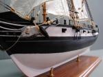
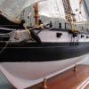
Brigantine "Newsboy" 1854 pictures:
-
Don9of11 reacted to Pete Jaquith in Plank on Solid Ship Model Hulls
Plank on Solid Ship Model Hulls
By Pete Jaquith
Recent private messages have raised questions relative to the process for constructing solid ship model hulls. The following notes outline the process I used for plank on solid construction with built up bulwarks in scratch building the Maine Topsail Schooner Eagle 1847 illustrated in a build log here at MSW:
Shaping the Solid Hull:
1.0 Material – For scratch built solid hulls I prefer to work with basswood or sugar pine.
2.0 Templates – Station, deck camber, deadrise (if applicable), fore/aft deck endings, fore/aft cap rail endings, and stem & stern frame profile templates were prepared by pasting copies of the body plan and forward/aft hull lines on firm card stock or matt board.
3.0 Hull Block Fabrication – Hull laminations were fabricated using a table saw. The hull block was laminated in rectangular form in order to allow accurate layout and shaping. I glued up the laminations using brown carpenters glue as the glue lines provide useful reference lines. Where appropriate, I laminate the poop deck as a separate assembly.
4.0 Reference Lines – Hull and deck reference lines were laid out with the hull block in rectangular form as it fascinates accurate layout the centerline, station, deck shear and deck at side lines.
5.0 Transom Assembly – The transom assembly was shaped using a disk sander to shape the transom or counter.
6.0 Deck Shear and Camber – A draw knife was used to shape the deck shear and camber. As a poop deck was involved, I shaped the main deck prior to installing the poop deck assembly.
7.0 Deck at Side – After layout of the deck at side molded breadth, a band saw was used to rough out the deck at side (leaving adequate material for tumblehome). A flat chisel was then used to carve the deck edge to the molded breadth using a downward sloping cut to allow for tumblehome.
8.0 Keel, Stem, and Stern Profile – The next step was shaping the keel, stem, & stern profile. Where material needs to come off the keel line, I use a draw knife or block plane. For shaping the stem and stern profile a flat chisel, mill file, and round sanding drums were used.
9.0 Carving the Hull Surface – The hull was carved to the exterior hull lines while secured in the inverted position on a building/reference board. The deadrise was carved using a draw knife. The stations were then roughed out the stations using a sharp gouge. Fairing between stations was performed using sharp gouges to remove the majority of material followed by a #49 Pattern Making file. An alternative to the pattern making file is #80 open grit sand paper wrapped around a 1 ¼” and 1 ½” dia. hard wood dowels.
10.0 Upper Hull Recess – For vessels such as Eagle and Newsboy with copper sheathing, I recess the upper hull and plank only the upper hull above the copper line.
Constructing Built up Bulwarks:
1.0 Bulwark Timberheads – Bulwark timberheads were slotted into the solid hull. I fabricated the waterway 1st and used it as a template to cut the slots. I recommend slotting every 2nd timberhead in flat areas and every timberhead in curved areas. After installation the timberheads were faired on both the interior and exterior surfaces using sanding sticks.
2.0 Bulwark Planking – Bulwark planking was installed in the normal manor working down from the upper strake or up the plankshear. I dry fitted the plank shear and cap rails for installation after paint in order to achieve a sharp paint line. On my Topsail Schooner Eagle 1847 build, I cut the bulwarks scuppers in the lower bulwark strake prior to installation.
3.0 Cap Rails – Cap rails were built up with scarf joints and edged with double bead stock. The cap rails were dry fit for installation after paint in order to achieve a sharp paint line.
Planking and Finishing the Hull:
1.0 Hull Planking – Hull planking was installed in the normal manor working down from the plankshear. I dry fitted the plank shear for installation after paint in order to achieve a sharp paint line. For full lined vessels with flair forward such as the Topsail Schooner Eagle 1847, the expanded planks curve down at the bow and should be cut from sheet stock. The transition between the planked topside and solid lower hull was faired with wood filler.
2.0 Coppering the Hull – Copper sheathing was installed after completion of hull planking and hull painting. My notes on coppering the ship model hull are posted elsewhere at MSW.
Using the above techniques, I was able to accurately fabricate and carve the ship model hull for my Topsail Schooner Eagle 1847 build. While my Brigantine Newsboy 1854 build started as a machine carved hull, similar techniques were used.
I should note that the above approach generates a limited amount of sanding dust but a lot of wood chips (most of the material is removed by draw knife, gouges, and chisels). A good shop vacuum is a critical tool here. I have attached pictures of the Topsail Schooner Eagle 1847 (laminated solid hull, scratch) and Brigantine Newsboy 1854 (machine carved hull, kit) illustrating the process.
Pete Jaquith
Shipbuilder
Topsail Schooner "Eagle" 1847 pictures:
-
Don9of11 reacted to SketchupModeller in HMS Pandora (1779) CAD build log
Part 6: Getting ready to form the hull
After a bit of a delay, I'm back.
Back on page 2 (and almost a year ago!), the stations were defined. The stern needs to be defined, and the bow and topsides still need a little work before the surface can be skinned. These will be the subjects of today's post.
The edges of the transom, counter, and stern timbers were drawn in by tracing these timbers from both the body and sheer plans (purple lines) and projecting to an intersection, as shown below. The final edge is highlighted in red. The aft edge of the wing transom (green line) was traced from the framing plan, and the blue line follows the rabbet on the sternpost. Note that the last few stations have been hidden for clarity.
Next, lines were drawn in to define both the lower and upper edges of the hull's shape. The lower edge is simplest, as it merely connects the bottom ends of the station lines. Forward of the foremost station, this line continues up the stem, so that it defines the profile of the hull as seen on the sheer plan. Later, this line will be used to form the rabbet. The point at which this line terminates is taken from the sheer plan. Only the forward portion is shown below, but this line (blue) continues all the way aft.
Most of the upper edge was drawn in using the same method of connecting station to station and tracing from the sheer plan when needed (for example, at the scrolls). Finally, a curve was drawn in to connect the first few stations and the forward line described above. For this, I tried a number of different splines and curves included in the BezierSpline plugin until I found one that looked reasonable.
The end result of all of this was the construction of a number of closed loops that together will make up the surface of the hull. The next post will discuss how to create this surface.
-
Don9of11 reacted to AON in HMS Bellerophon 1786 by AON – scale 1:64 – 74-gun 3rd Rate Man of War - Arrogant-Class
Presently busy realigning all previous station frame outlines to intersect with the upper rabbet line.
Amazing just how much an error will teach a person