Valeriy V
-
Posts
1,116 -
Joined
-
Last visited
Content Type
Profiles
Forums
Gallery
Events
Everything posted by Valeriy V
-
 Thank you Joachim! The worst assumptions were confirmed, alas.
 -
Daniel! Thank you for your interesting and useful information! Based on Blagoev’s model, I propose to depict one grate for the water box on the left side.
-
Thanks for your story! This explains a lot about my failed attempts.
-
Thank you Joachim! If your experience is successful, please let me know. This means the bottom rectangular hole is for water inlet, and the top one is for outlet.
-
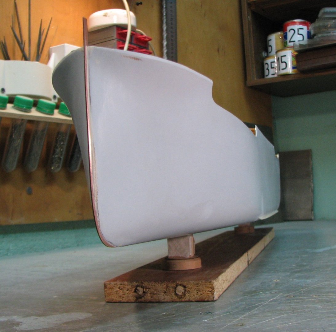
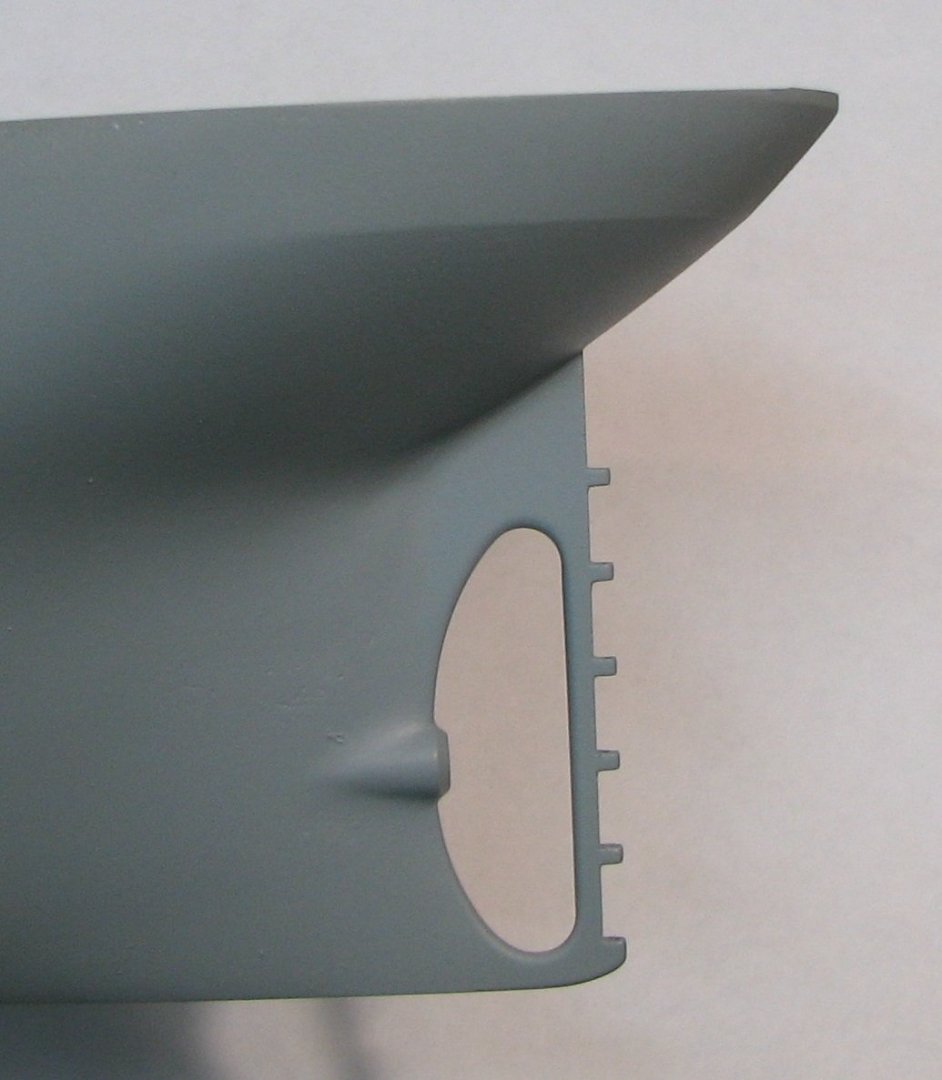
Most likely, this rectangular and relatively large hole is really for receiving water from the condenser. It is located at the very bottom of the vertical side, at the side keel. A little higher to the right you can see one round hole.
-
Thanks for your help and feedback! If this is a hole for receiving water, then a grate should be installed on it.
-
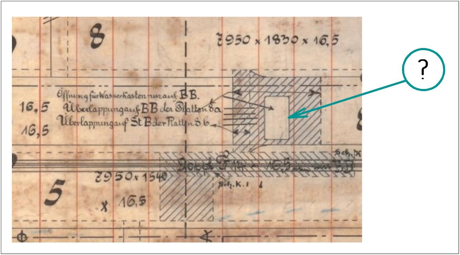
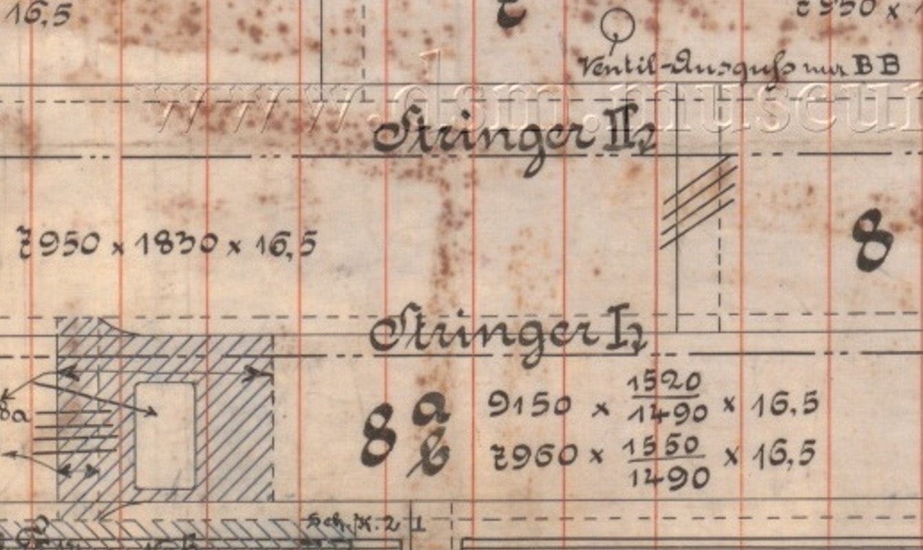
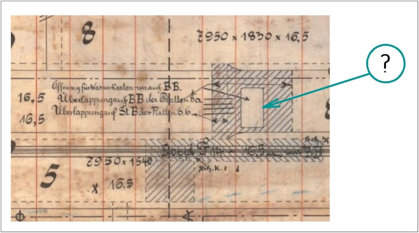
As usual, there are not enough drawings for the model, so I will use information from other ships. This is a fragment of a drawing of the outer cladding in German (ss UHENFELS ). I need your help in determining the name of this rectangular cutout, if of course there is this name on the drawing. It is located in the underwater part of the ship in the area of the engine and boiler room.
-
Sasha and Joachim, thank you for your nice reviews! By the way, I wanted to look at the work of German modelers and tried to register on the forum a couple of times. https://www.marine-modellbau-und-mehr.de/ But both times they didn’t let me go beyond the security check step. And now I’m at a loss as to whether I’m doing something wrong or whether I’m dangerous in some way (just kidding).
-
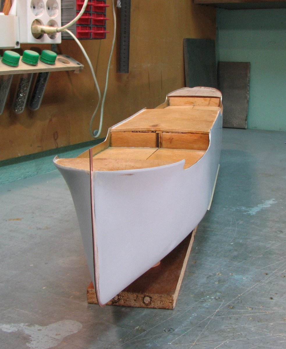
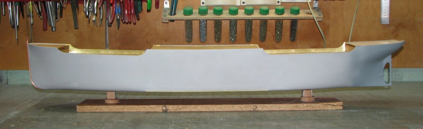
Photo of the general view of the model hull as of today. I have work ahead of me on deck.

-
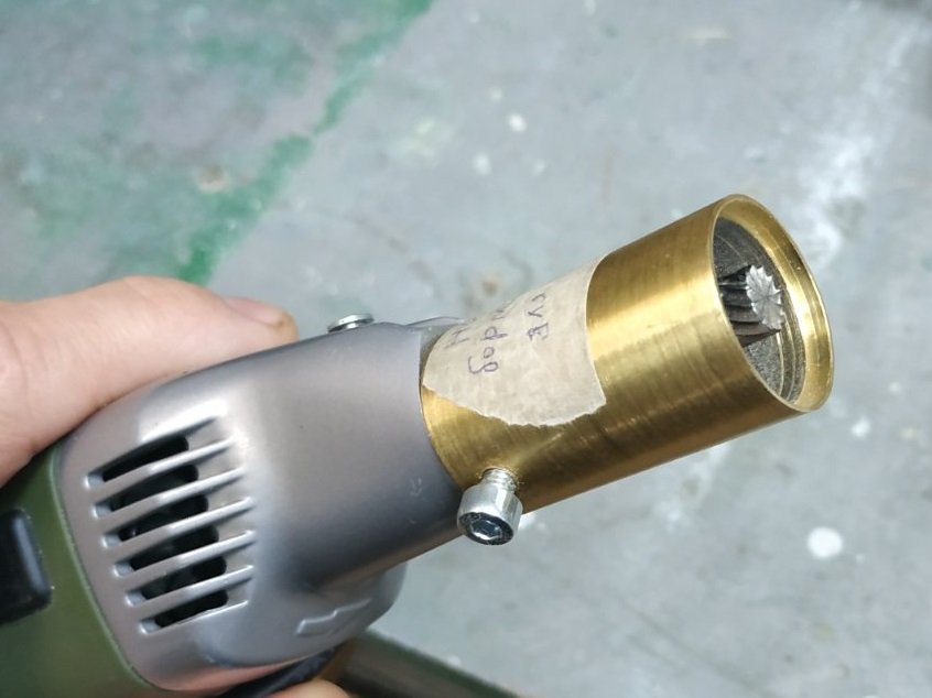
Using an ordinary cutter and a homemade depth stop.
-
Bob, unfortunately, Google translator distorted my thought a little, but oh well - it doesn’t matter anymore. I am grateful to you for your warm feedback about my efforts, thank you!
-
Thanks Bob for the useful information. I already realized that my advice is unnecessary for residents of the US and EU. And, as I wrote earlier, I do not have such a choice and I am forced to work with what I can buy.
-
It should be added that after adding acetone to the putty, it cannot be applied to metal parts. Only on wood and fiberglass with resin. This putty composition does not adhere to metal after drying.
-
Nils! I think yes, you can work with a brush. But we must take into account that the hardening speed of this putty is greater than that of paint and you cannot hesitate. And most importantly, after mixing the two components, the putty must be diluted with acetone until it is very liquid. And you will have approximately 20-30 minutes for the entire operation.
-
Nils! The deck on the model is currently made of plywood and is covered with a protective layer of varnish on top. But everything will change soon...

-
Wooden slats were removed from the inside of the bulwarks and a deck was installed.
-
The photo shows the installation of side keels.

-
The holes are drilled with an extended drill bit. First, 3 “steps” were drilled from the top, and then 3 from the bottom.
-
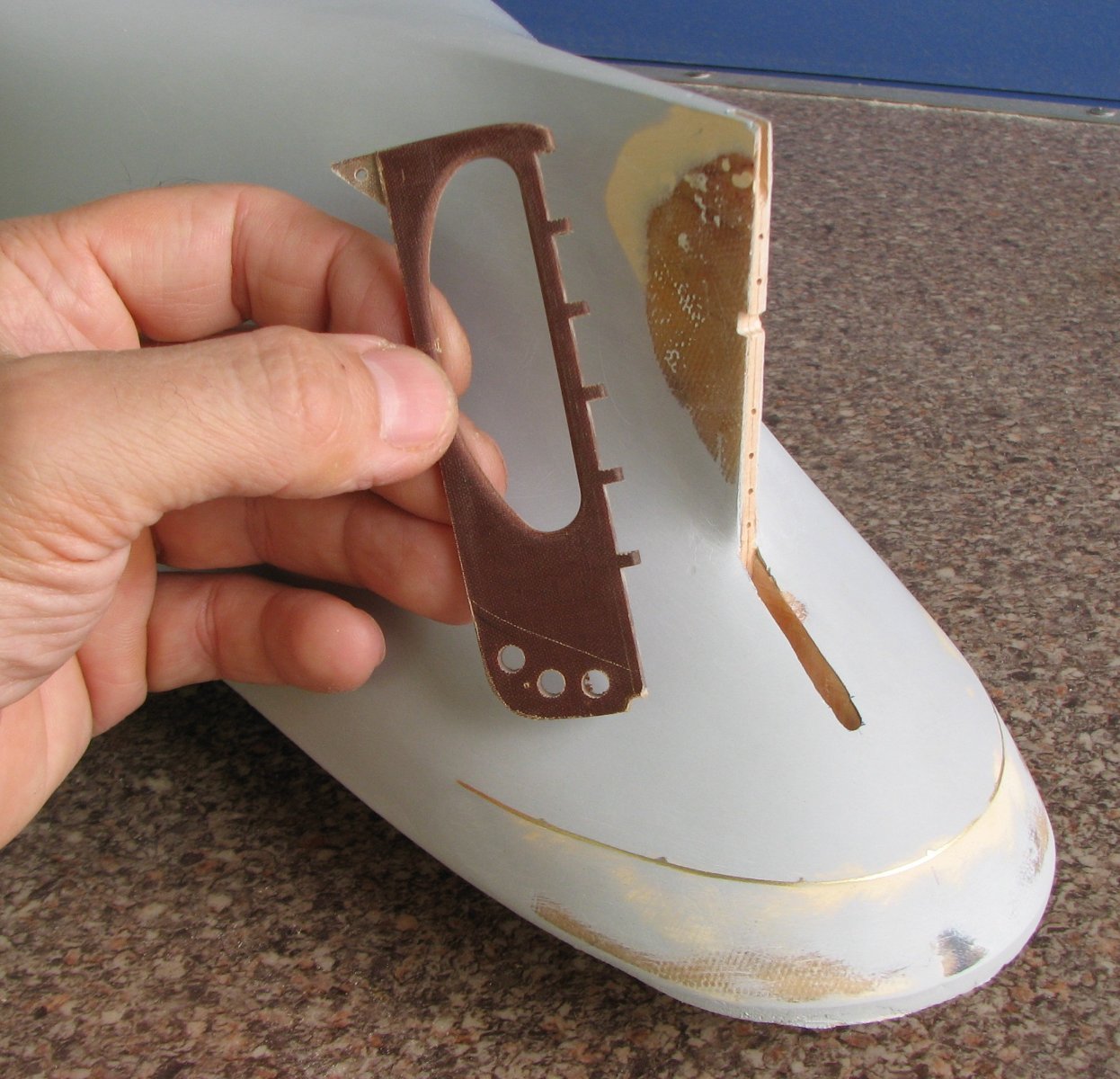
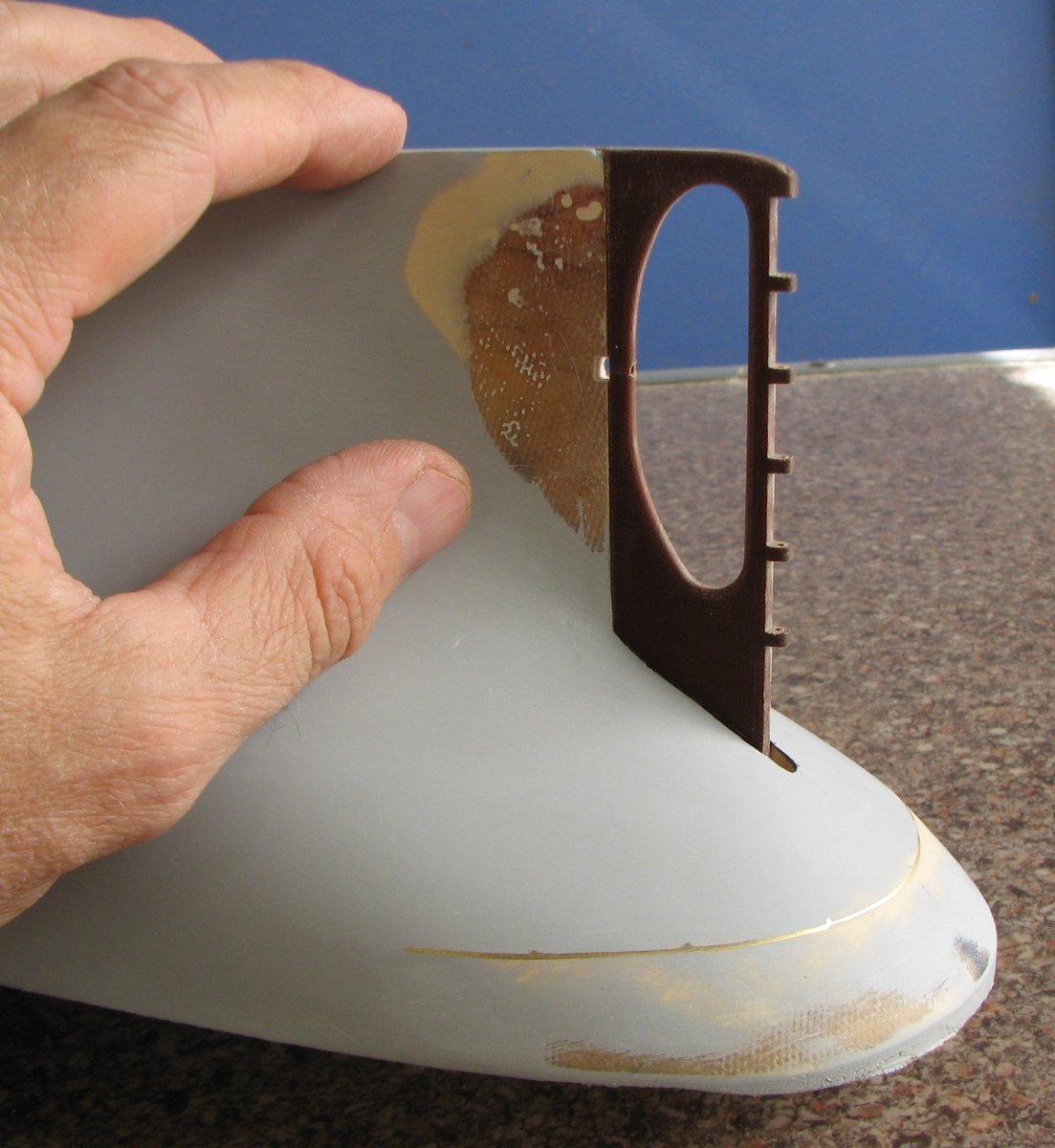
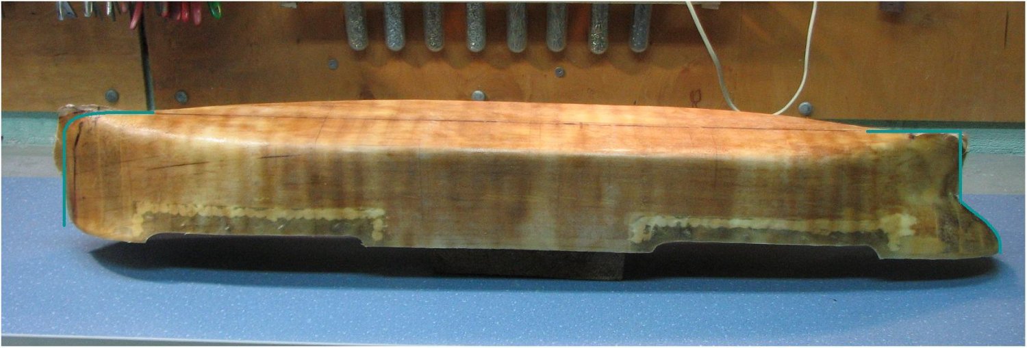
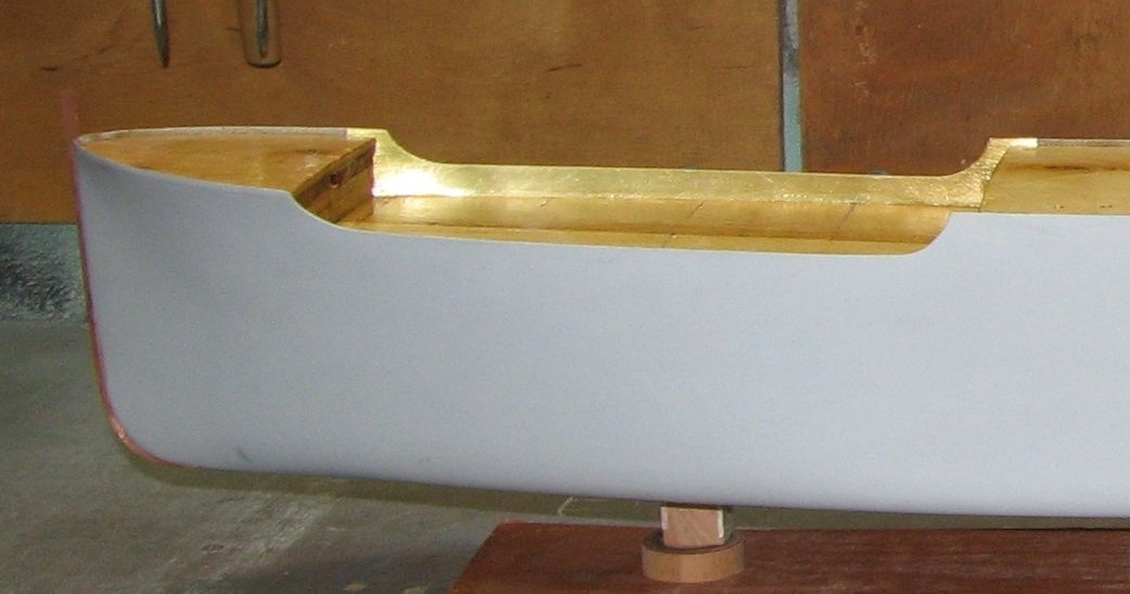
As a result, the rear part of the model looks like this
-
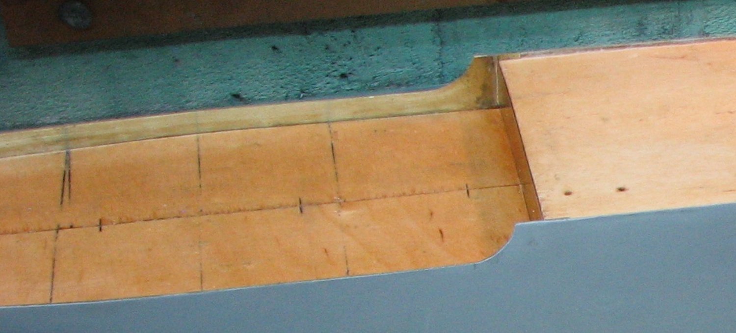
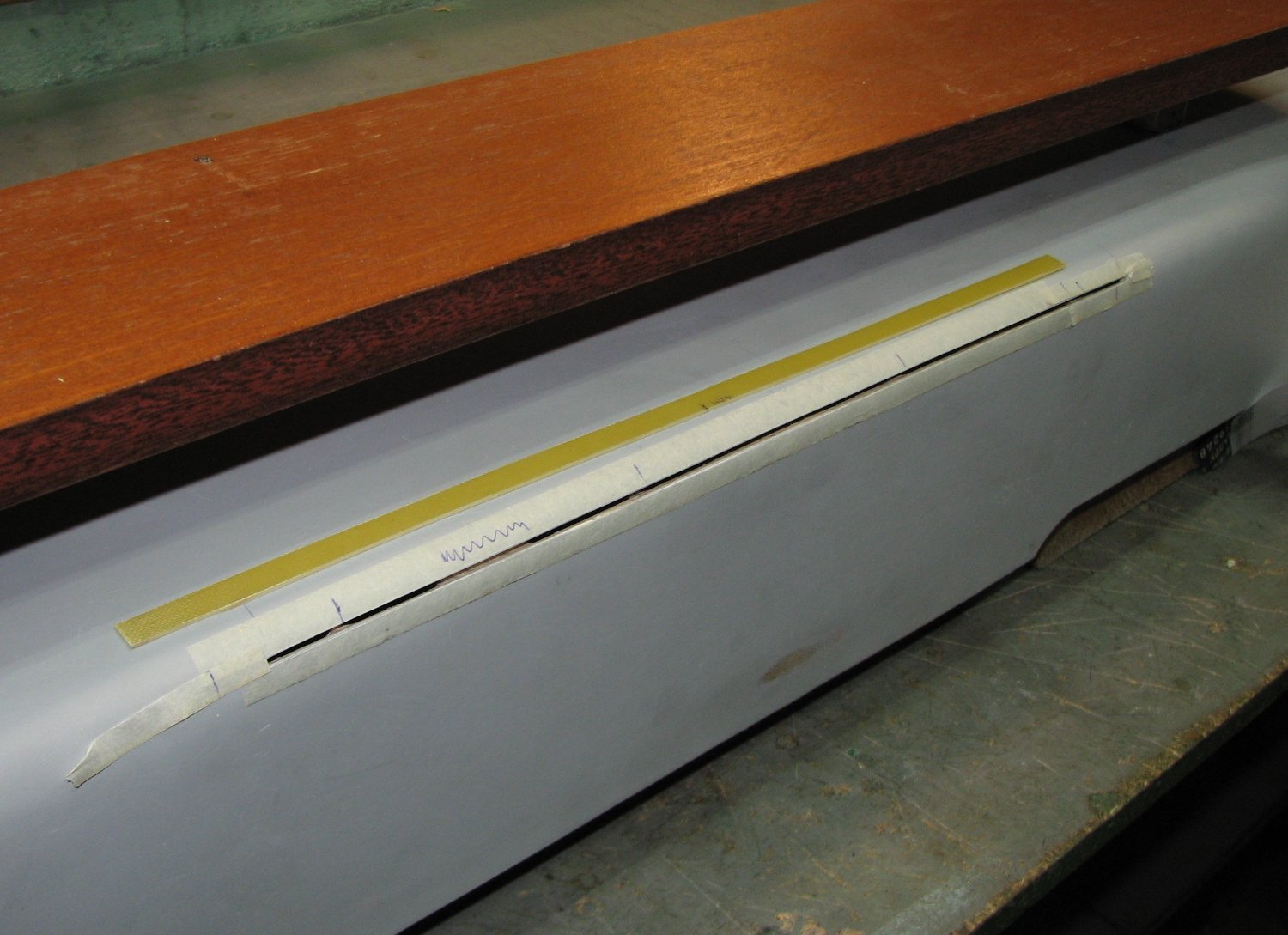
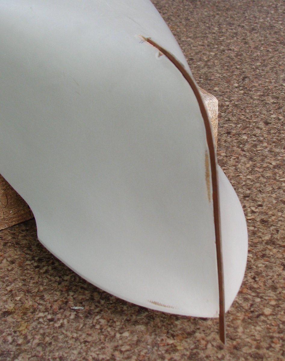
Making a break line in the stern.

-
Bob, I already regretted writing this phrase. We live in different conditions and I don’t have such a wide selection of hardeners as you do. And yet, with the resin that I have to work with, this is what happens. At the moment when it just begins to thicken on the hull of the model, I still have the opportunity to make it more liquid for a very short moment using a hairdryer. This technique allows me to have time to remove all excess resin from the model body and achieve an almost ideally smooth surface of fiberglass impregnated with resin, without lumps of excess resin.
-
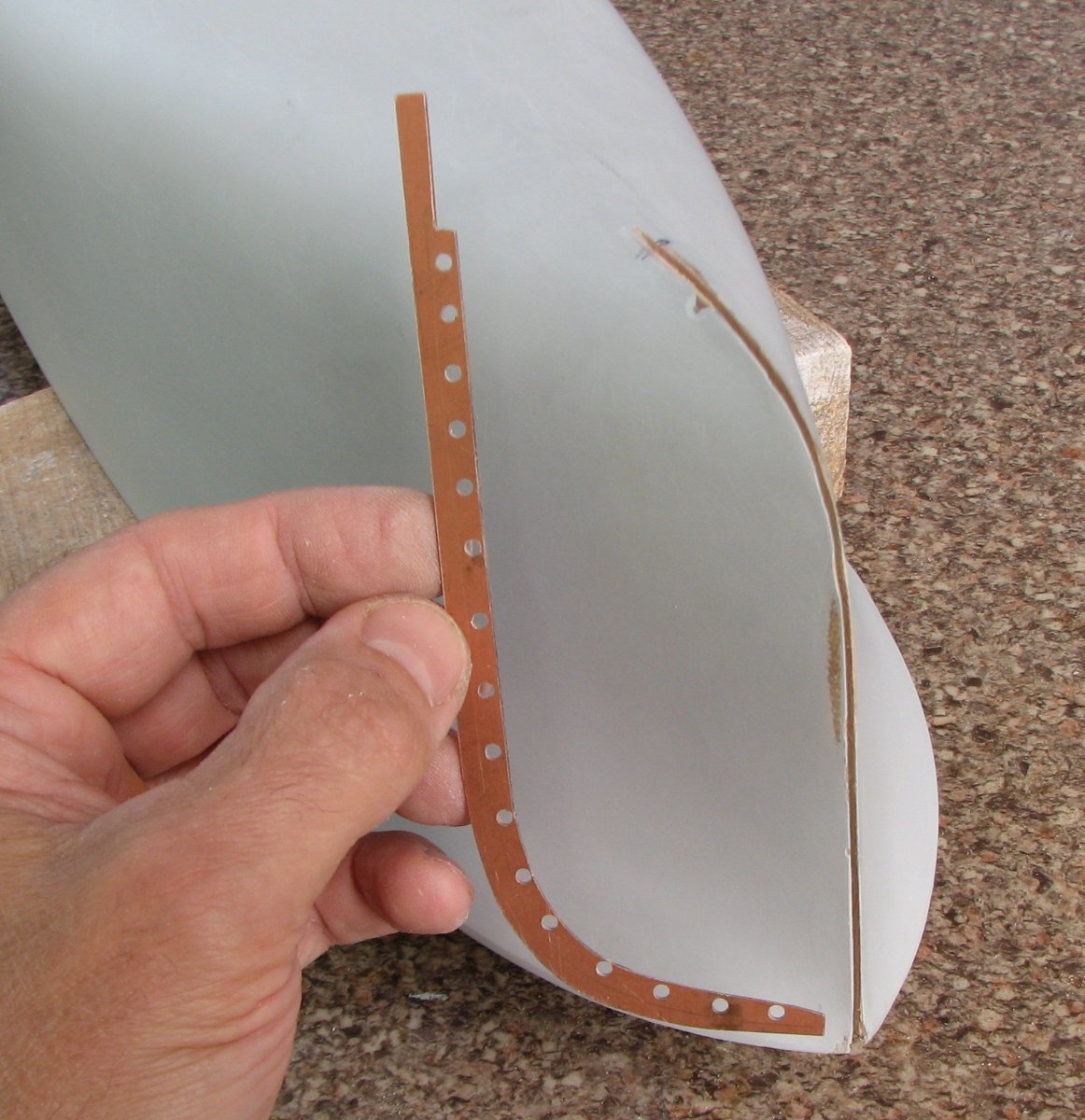
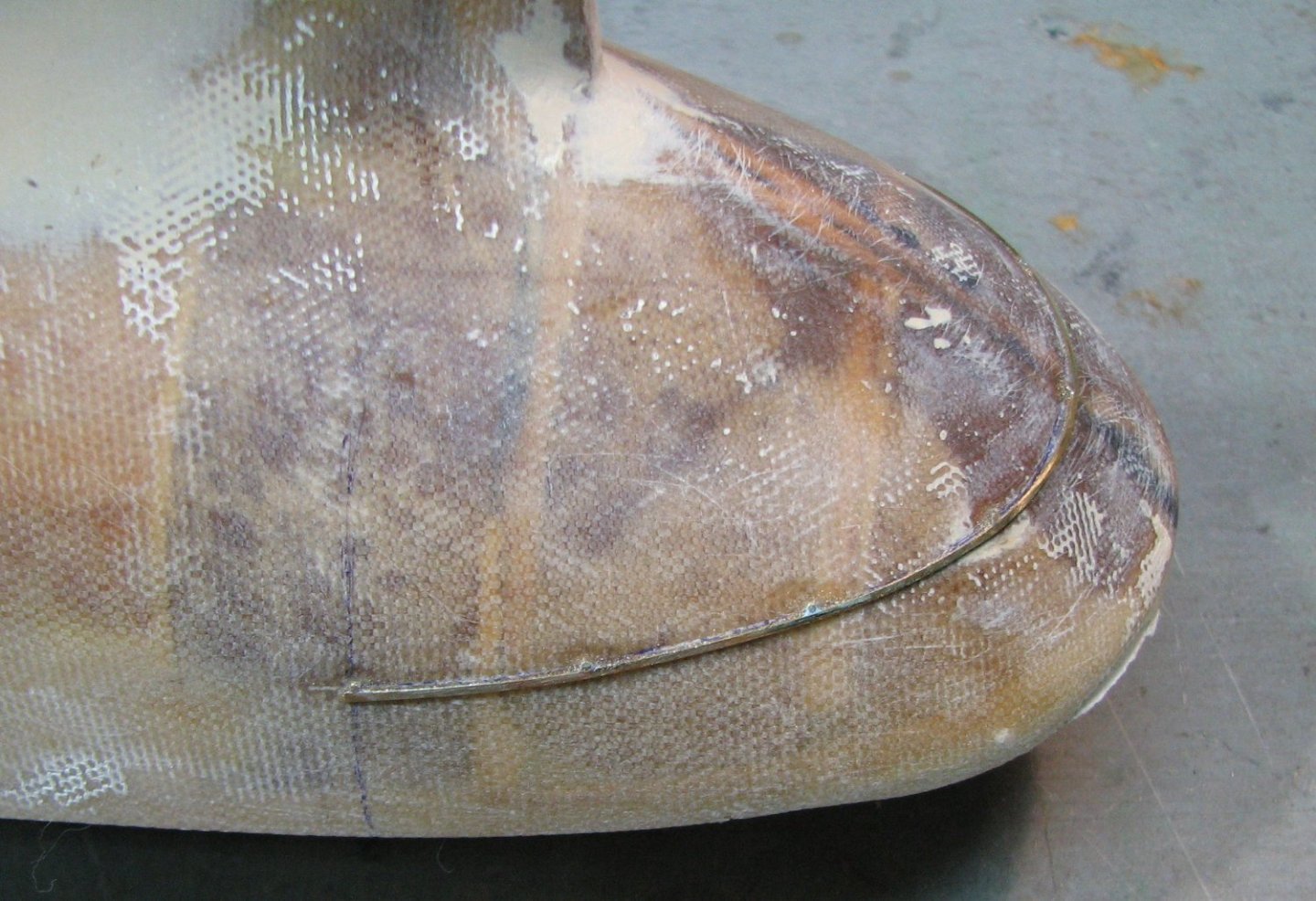
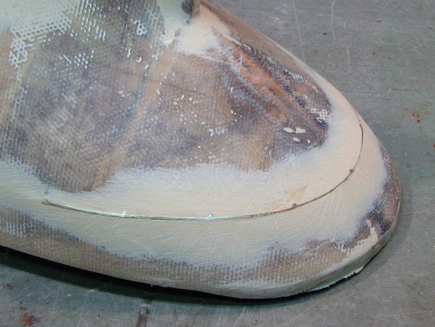
Avoiding wrinkles is not difficult: 1) I make cuts in the fiberglass fabric as shown in the photo along the green lines before applying the resin 2) after applying the resin in small portions, I smooth it along with the fiberglass with a soft rubber spatula 3) in case the resin polymerizes too quickly, I have a construction hair dryer nearby with which I can heat the desired area of the resin and fiberglass to liquefy it

-
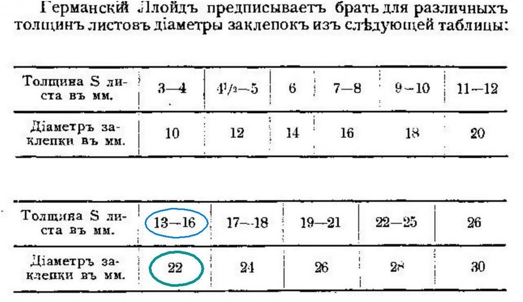
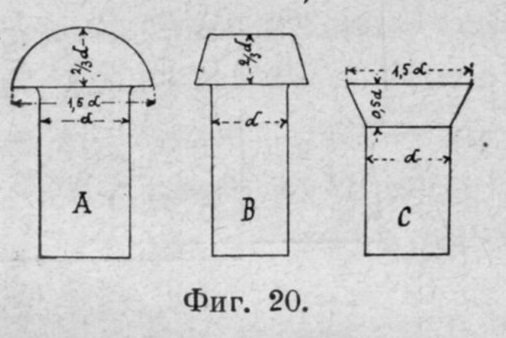
For rivet head size calculations I show the German Lloyd chart. Circled in blue is the thickness of the cooable panel sheet that I choose. Green color is the required rivet diameter. As a result of a simple calculation, I get the dimensions of the rivet head for my model on a scale of 1:100 - diameter 0.3 mm and height 0.15 mm. Even if I can make such small details on the model, after covering with primer and paint they will simply visually disappear. Therefore, it makes no sense to show rivets on this model. But the belts of the outer hull plating sheets will be shown.