Valeriy V
-
Posts
1,116 -
Joined
-
Last visited
Content Type
Profiles
Forums
Gallery
Events
Everything posted by Valeriy V
-
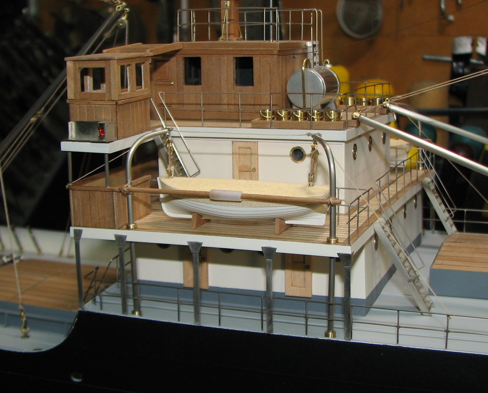
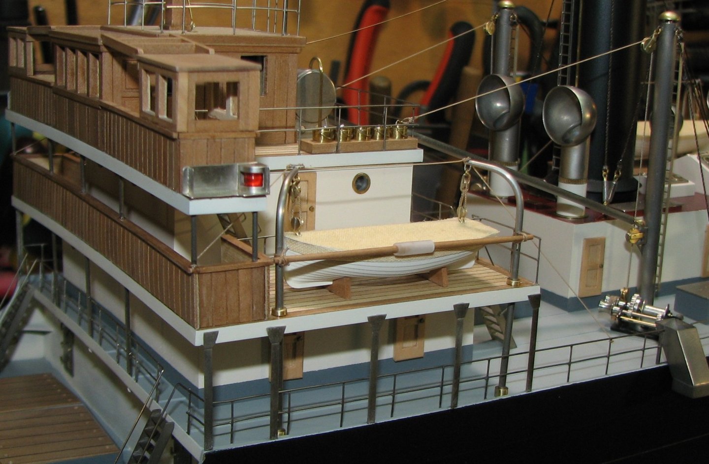
 I think it could have happened like this. To successfully take the boat overboard, this beam was lowered to the required level. At the same time, the beam remained connected to the davit and did not interfere with the work with the boat with its uncontrolled movements during the rocking of the ship.
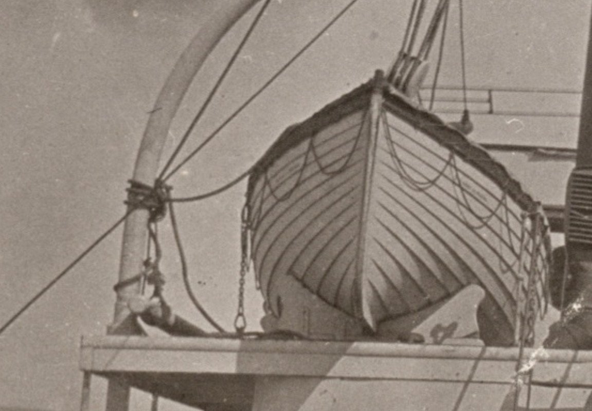
-
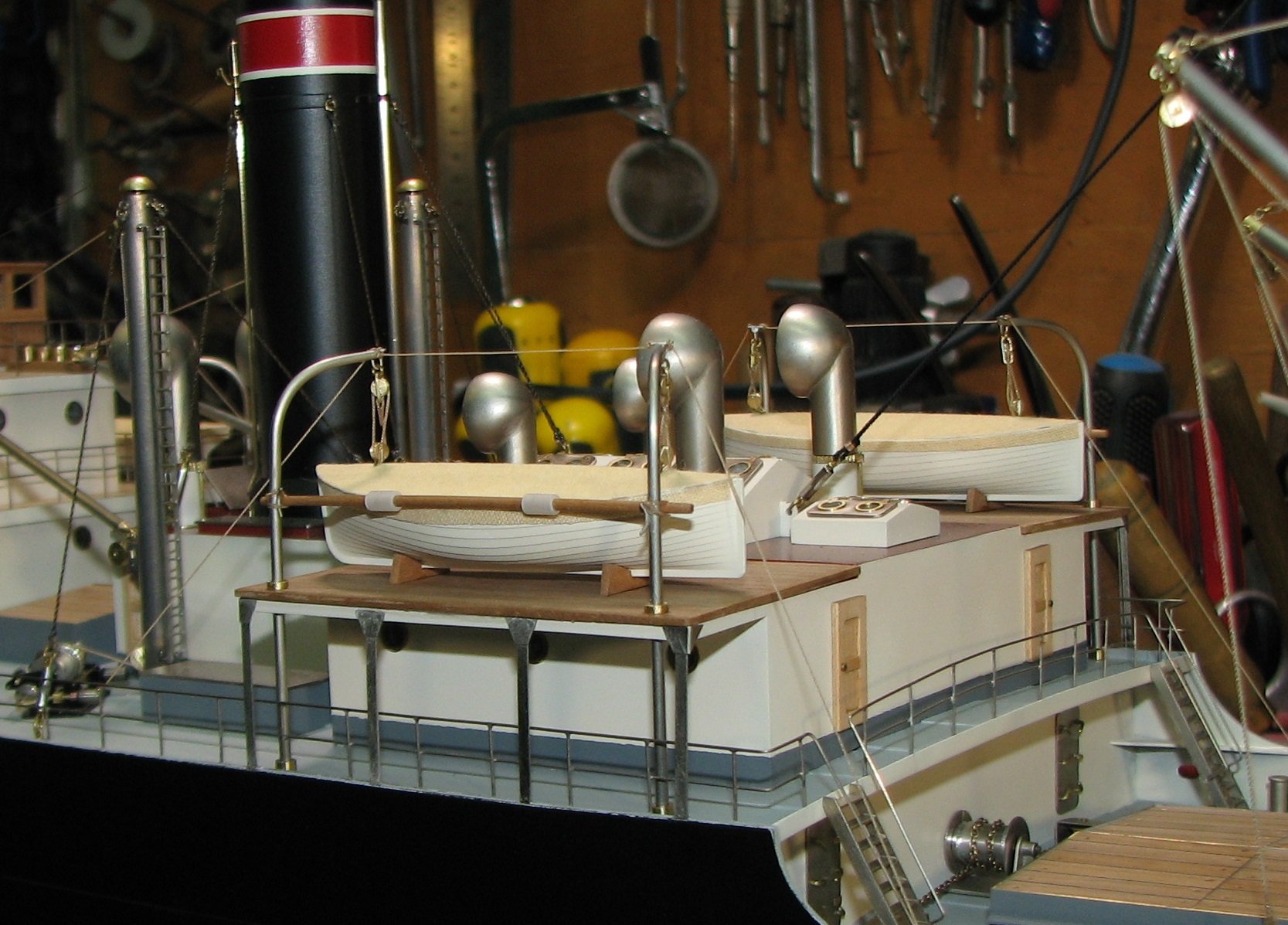
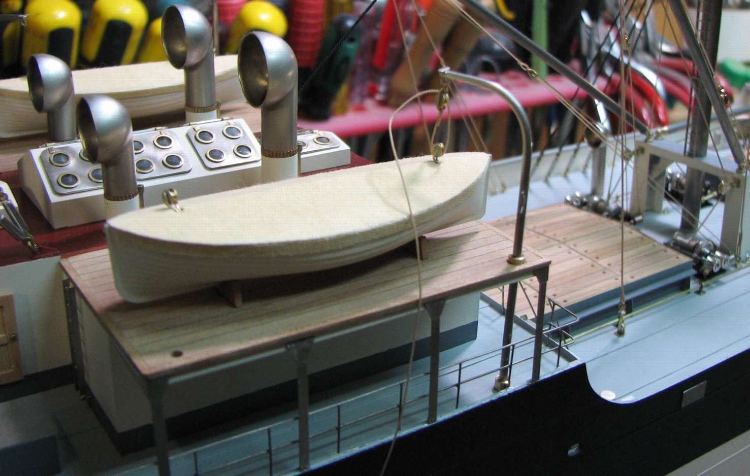
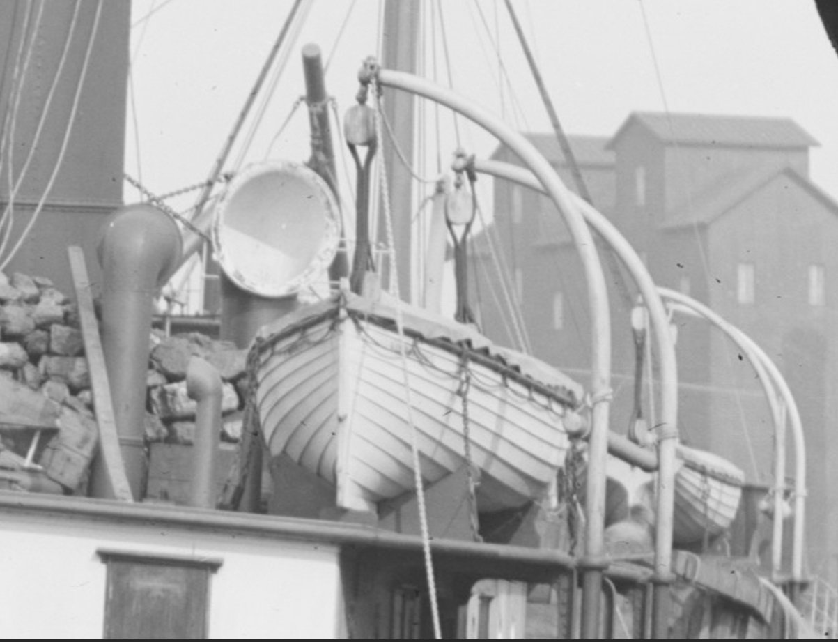
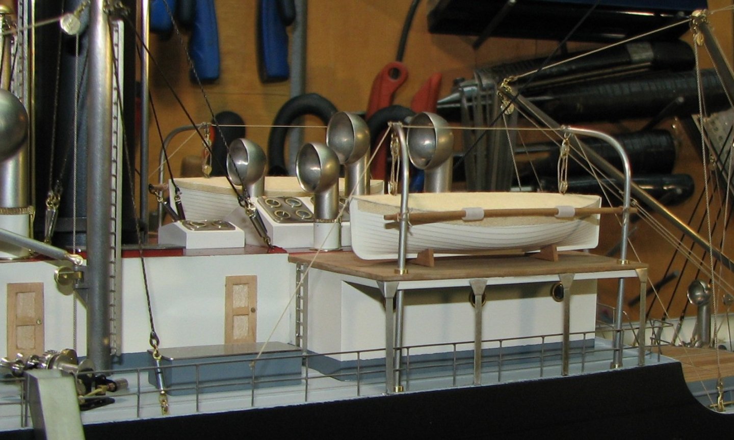
I think that in addition to dry and secure storage, they could serve as guard rails. This concerns the boats on the rostra.
-
Yes, I expected this question. In some cases, this griping spar was attached for storage as I depicted in the model.

-
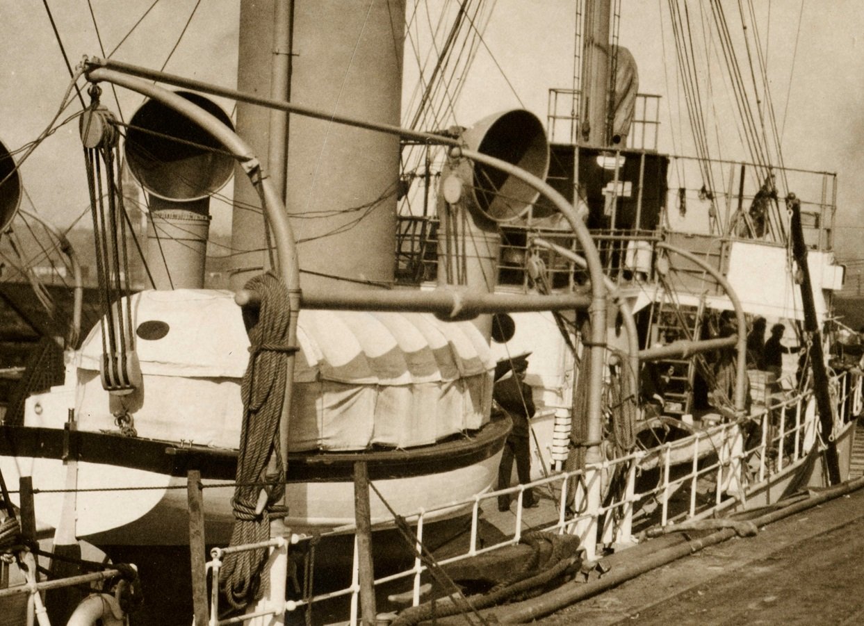
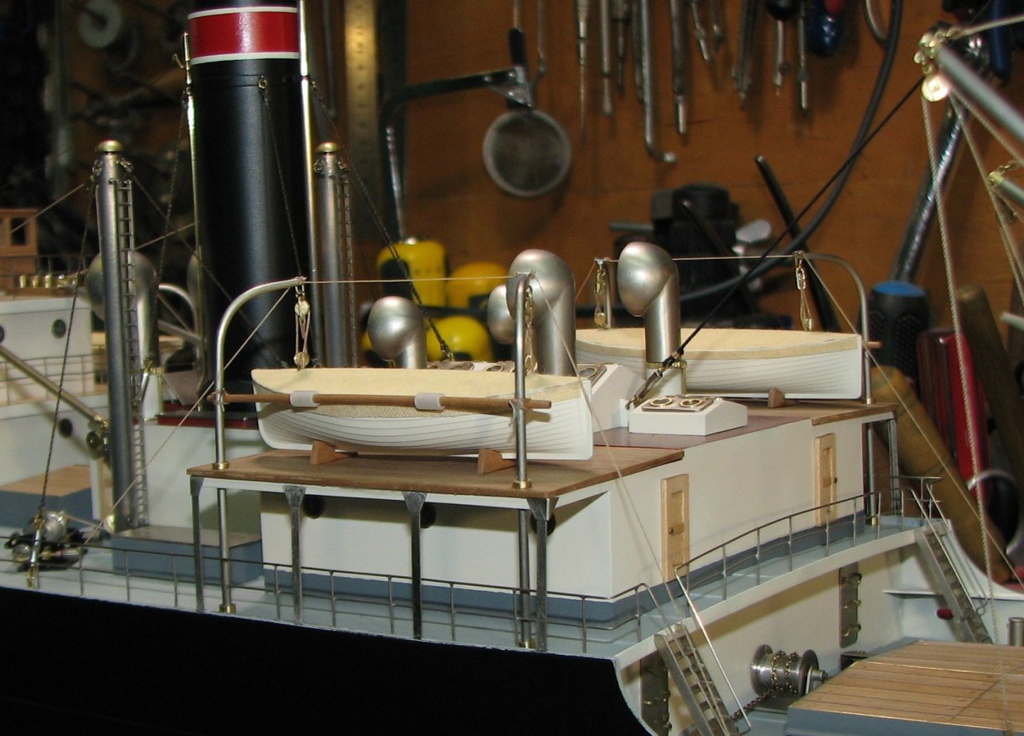
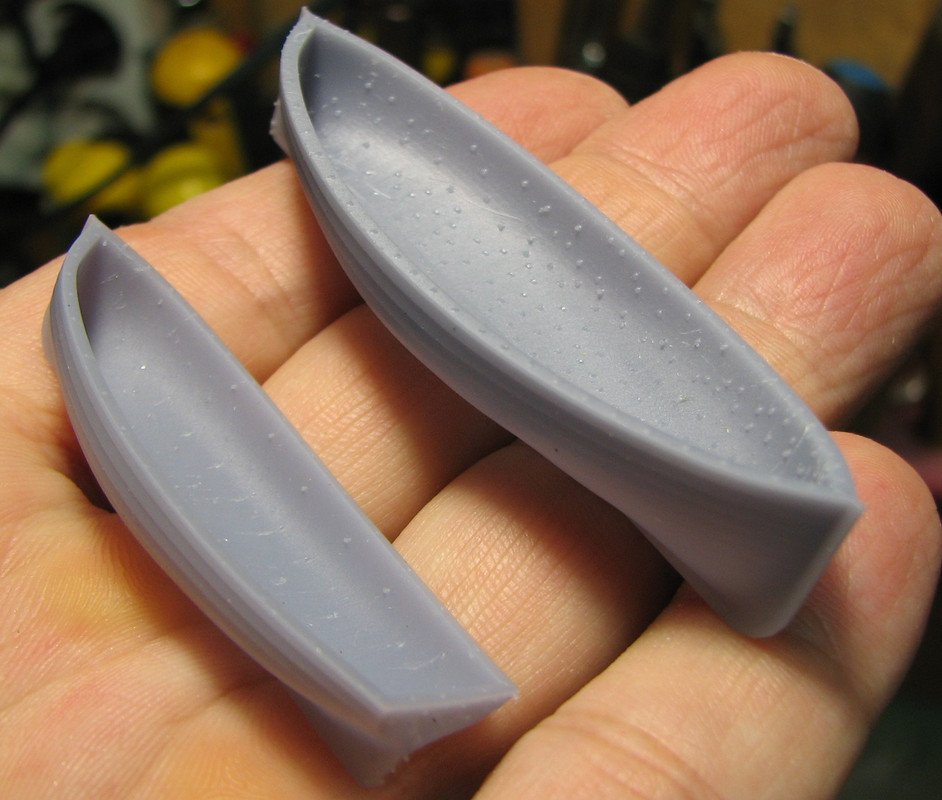
Lifeboats and workboats are installed in their designated places.

-
Yes, that's right. The boats will be covered from above.

-
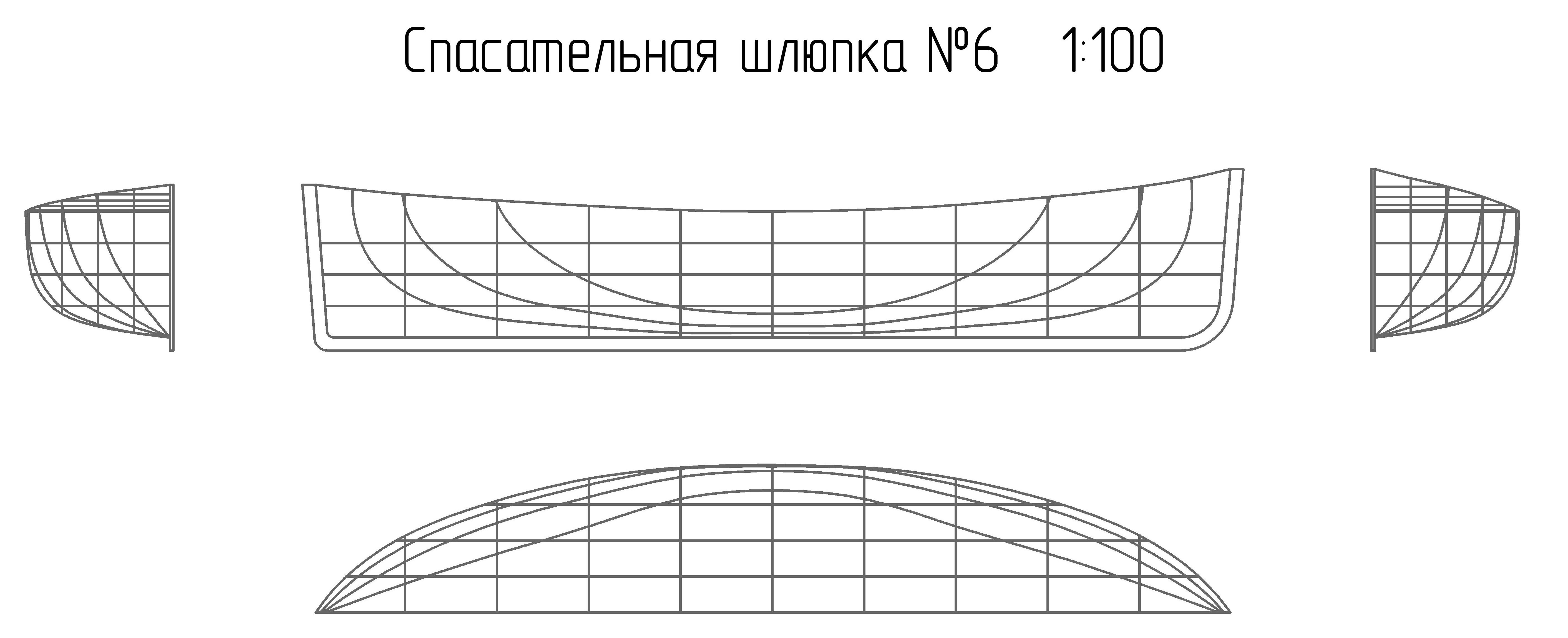
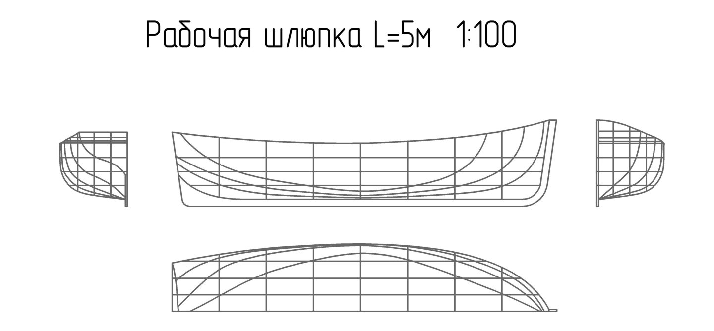
Nils, I am posting my plans for a workboat and a lifeboat. Perhaps they will be useful to you.

-
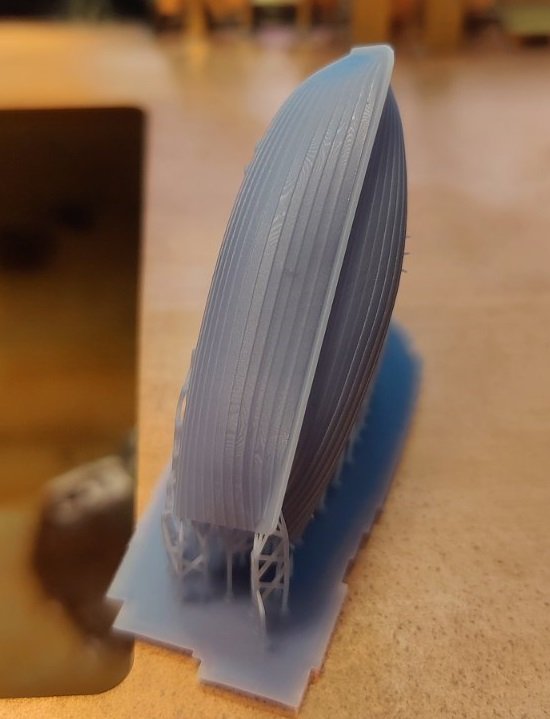
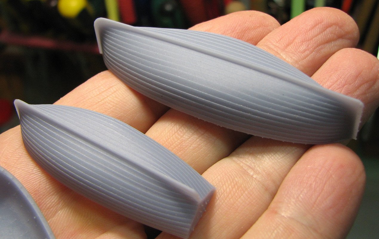
Thank you Nils! I drew the drawing of the boat hull myself according to the reference data taken from the USSR GOST. I don't have a 3D printer and I don't know how to draw drawings for it. But I have friends who helped me solve this problem according to my drawings of the boats.
-
Lifeboats are custom-made using a 3D printer.
-
Thanks, Greg! These models are ordered by owners of private collections. I have not yet interacted with museums, but I know that they tend to acquire simpler and cheaper models.
-
Yes, Tony, there's not much left to finish the process. I need to make and assemble the parts of the rescue device and think about how to make the letters for the name.
-
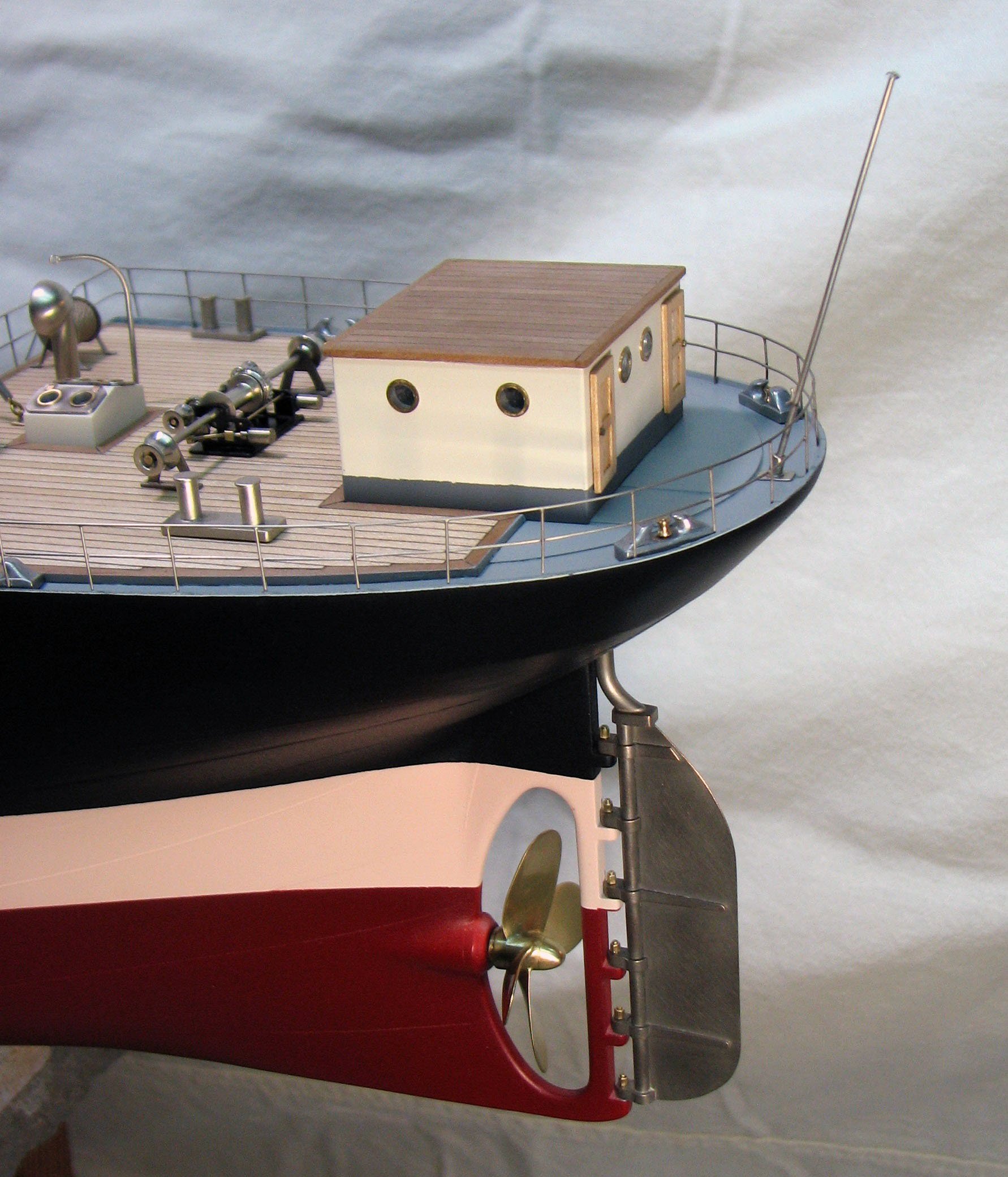
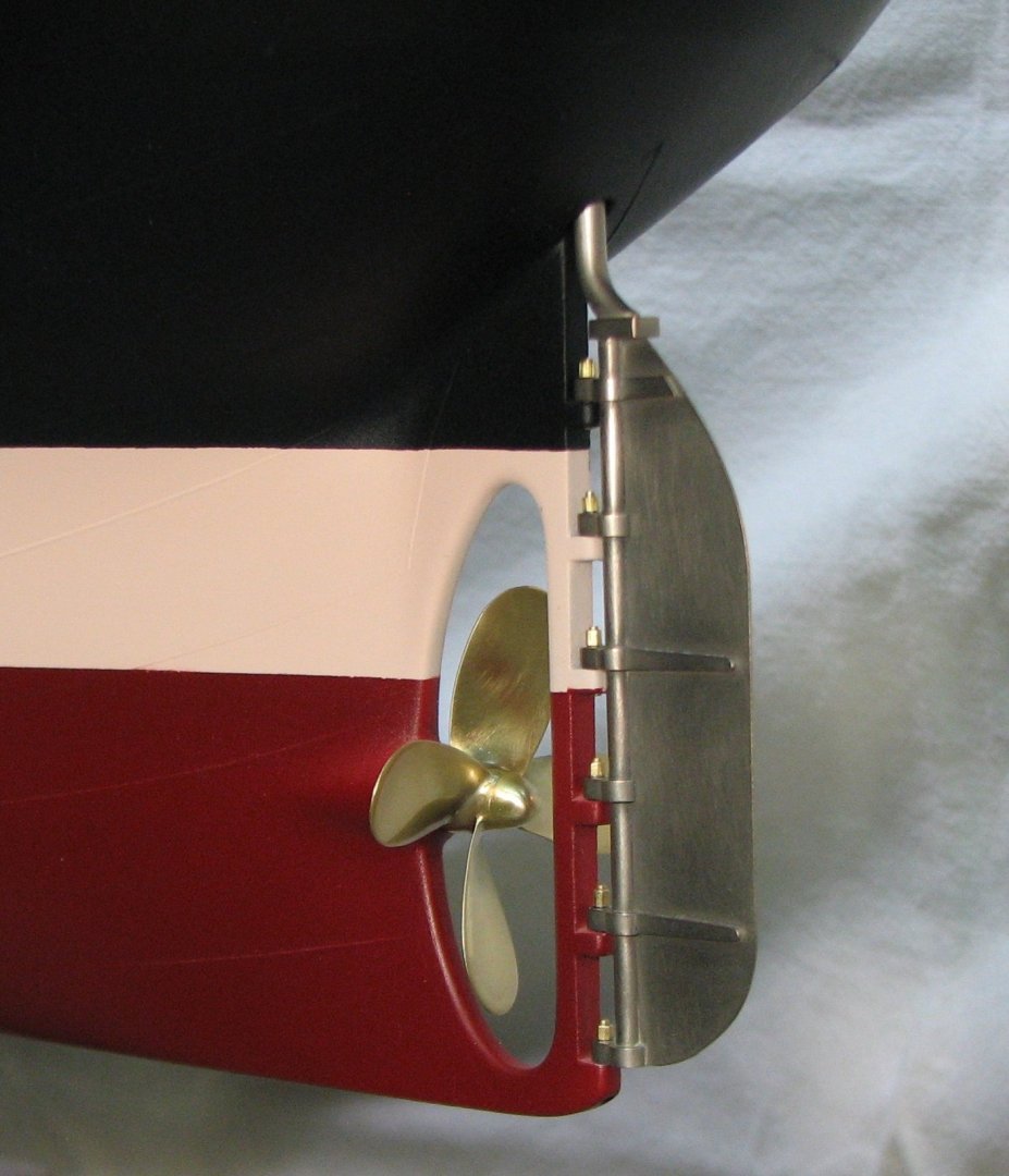
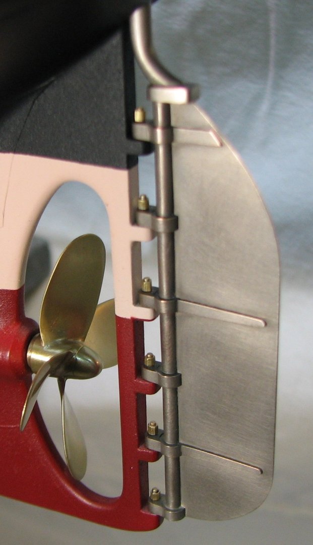
The propeller is installed in its place together with the rudder.

-
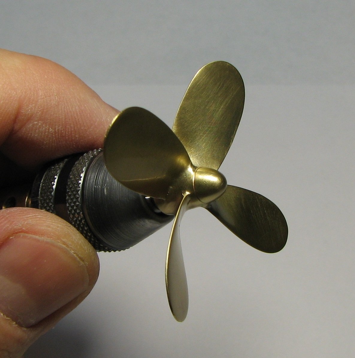
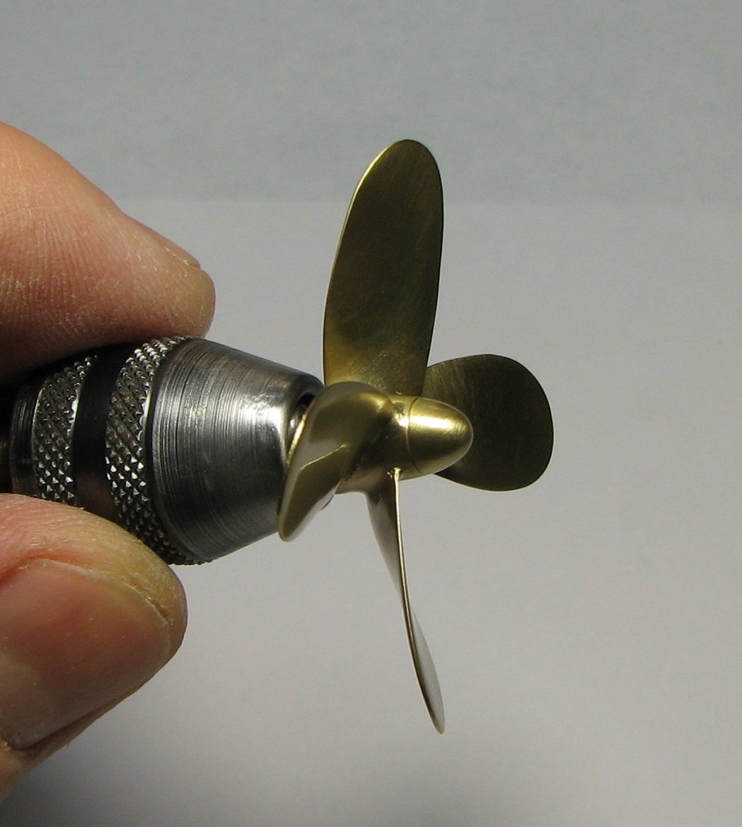
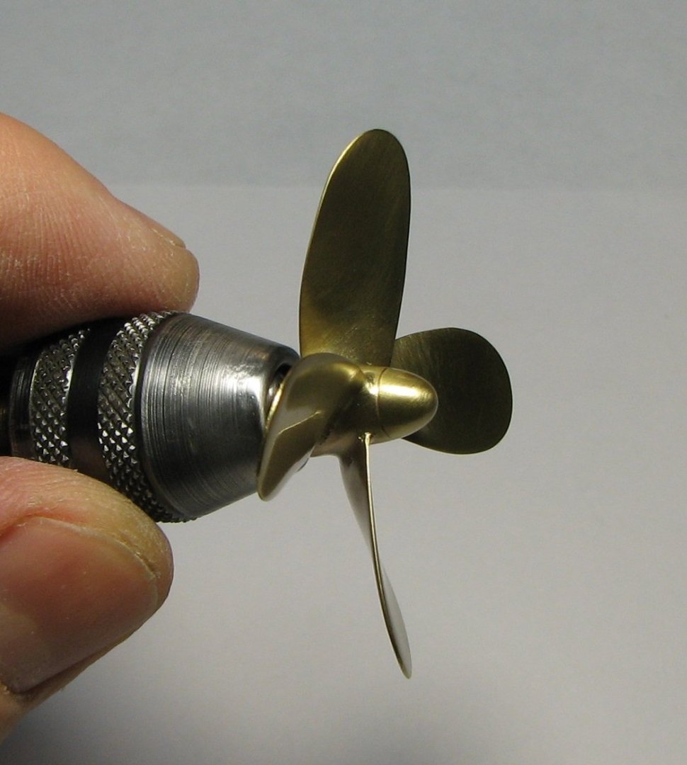
After polishing and adjusting the blade profile, the propeller took on a finished look.


-
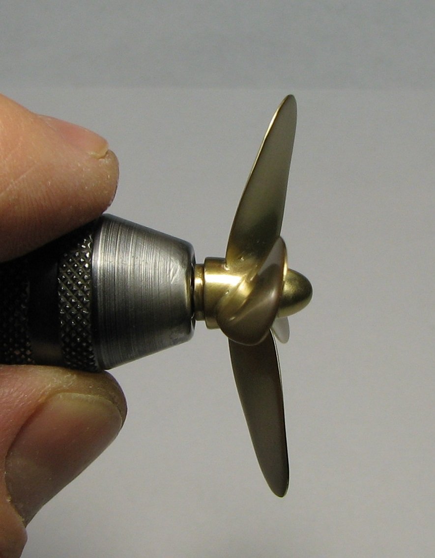
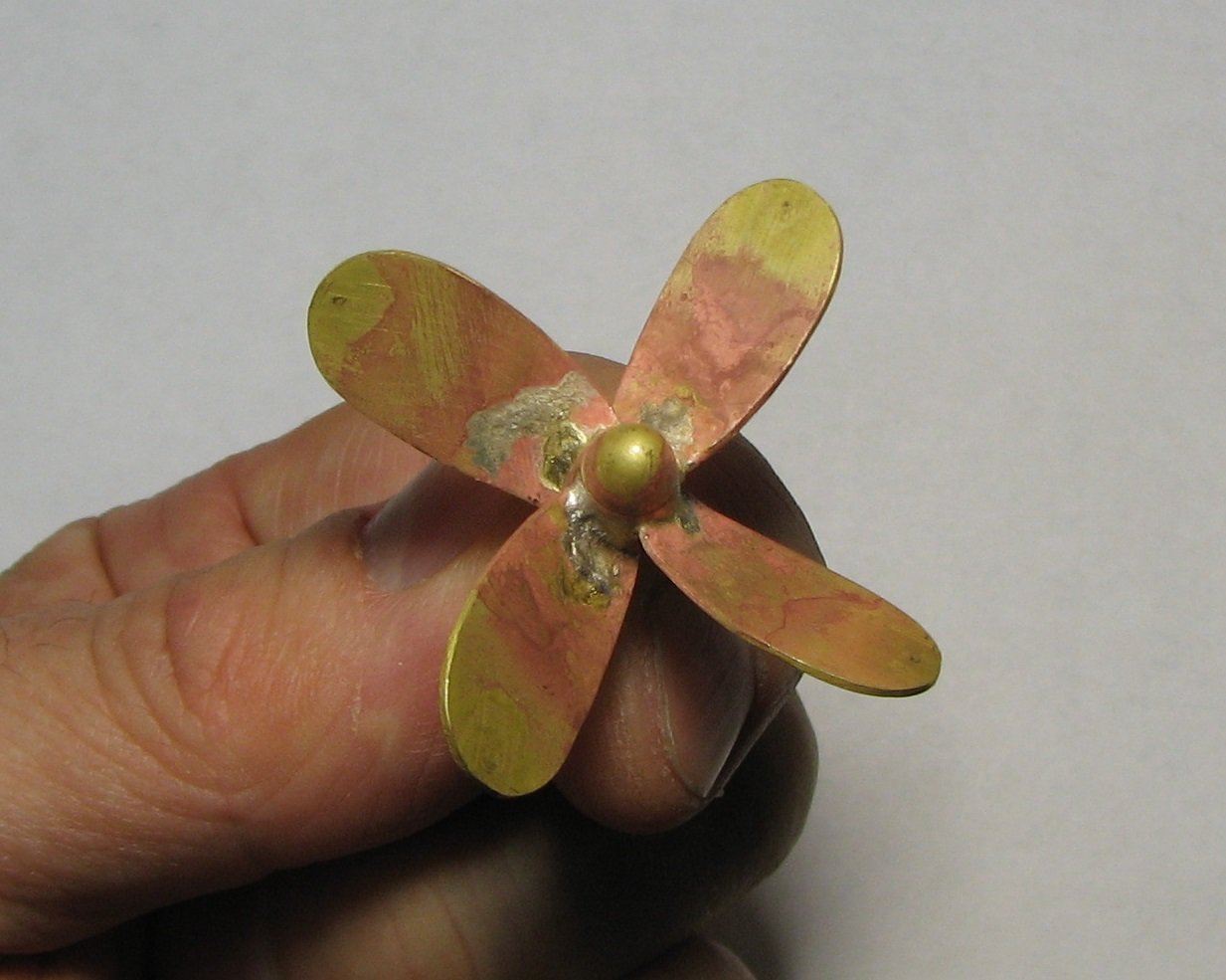
I then soaked the propeller in a citric acid solution for 30-45 minutes.
-
This is a photo of the propeller after the silver soldering process is complete.
-
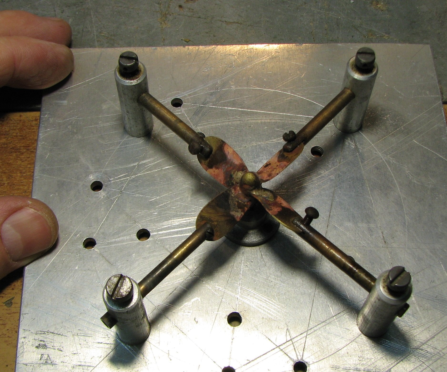
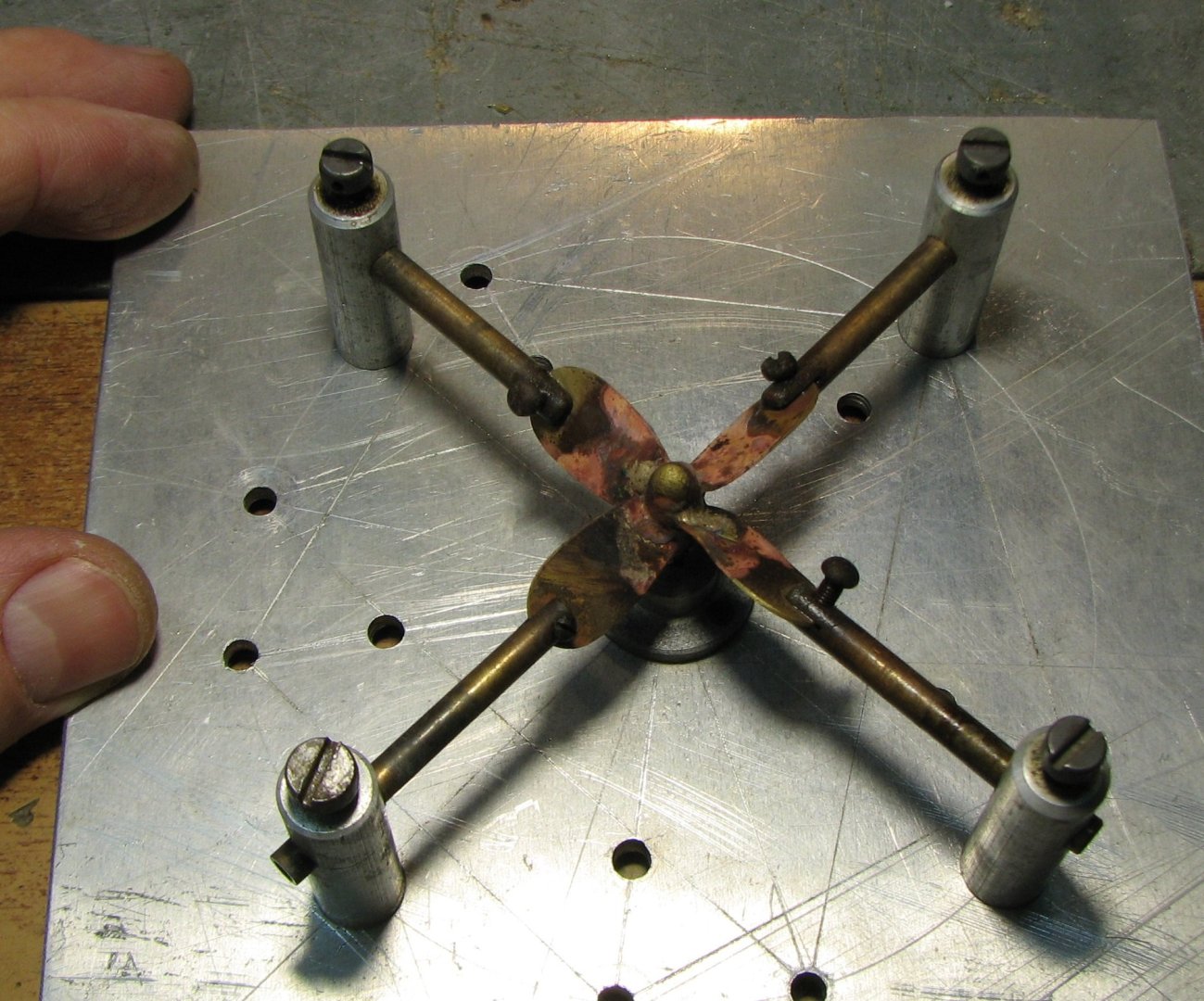
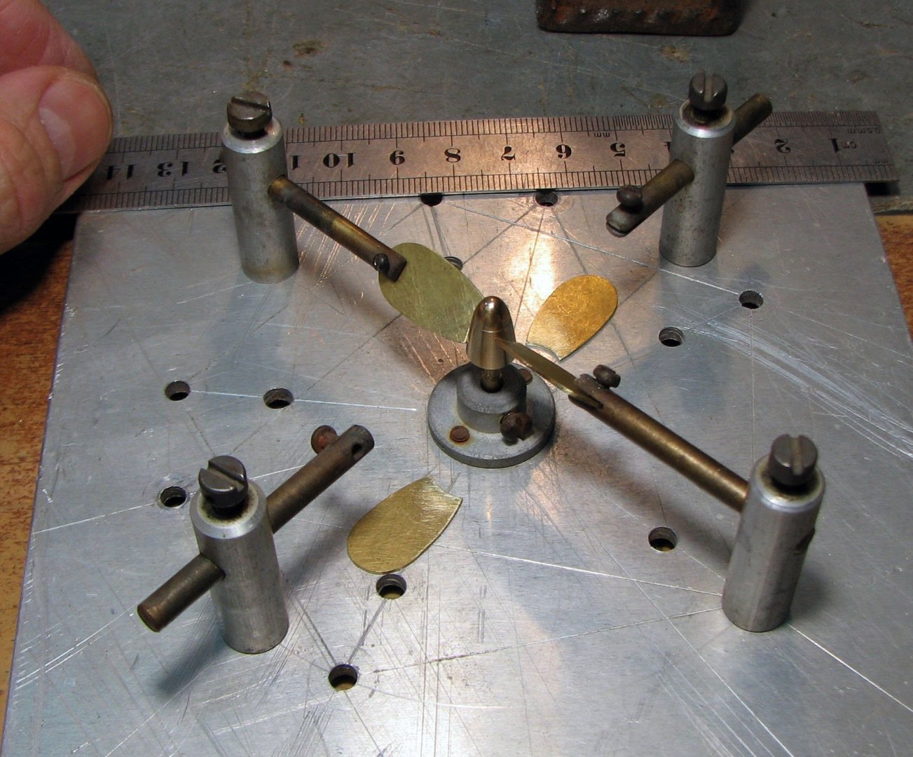
After that, it was time to make the propeller. The photo shows the process of assembling the parts on a soldering stand.
-
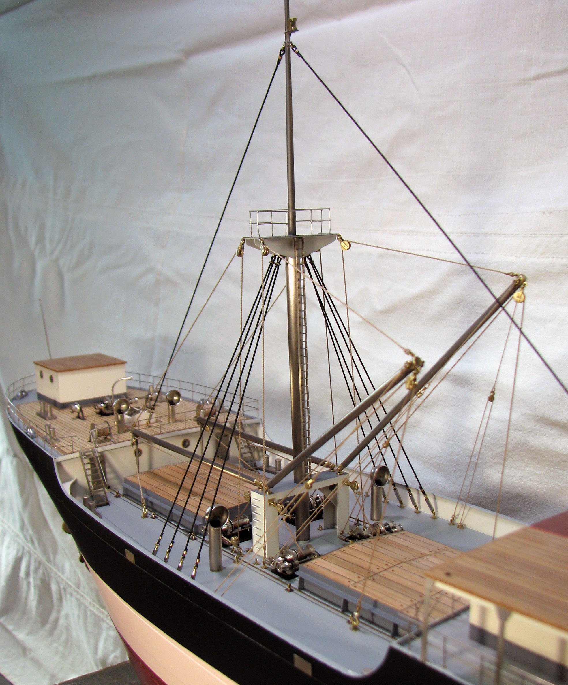
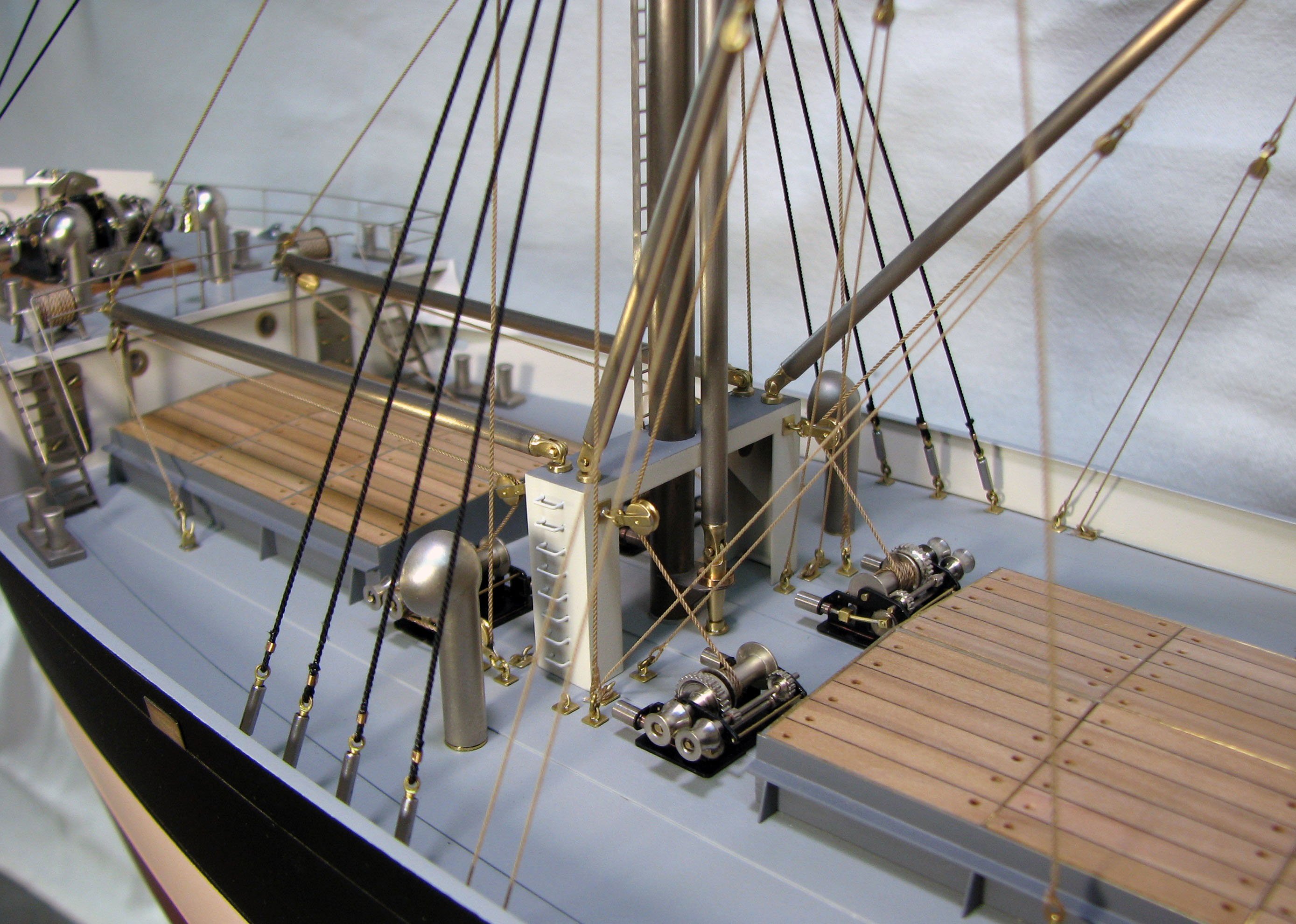
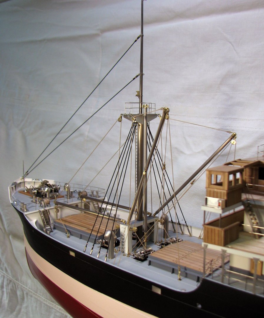
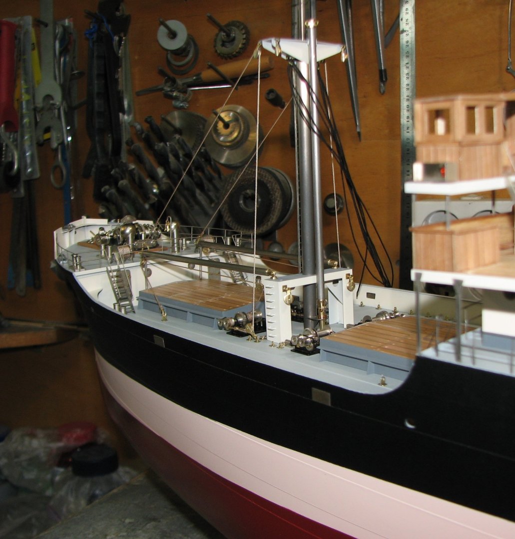
And now the mainmast cargo gear is assembled.


-
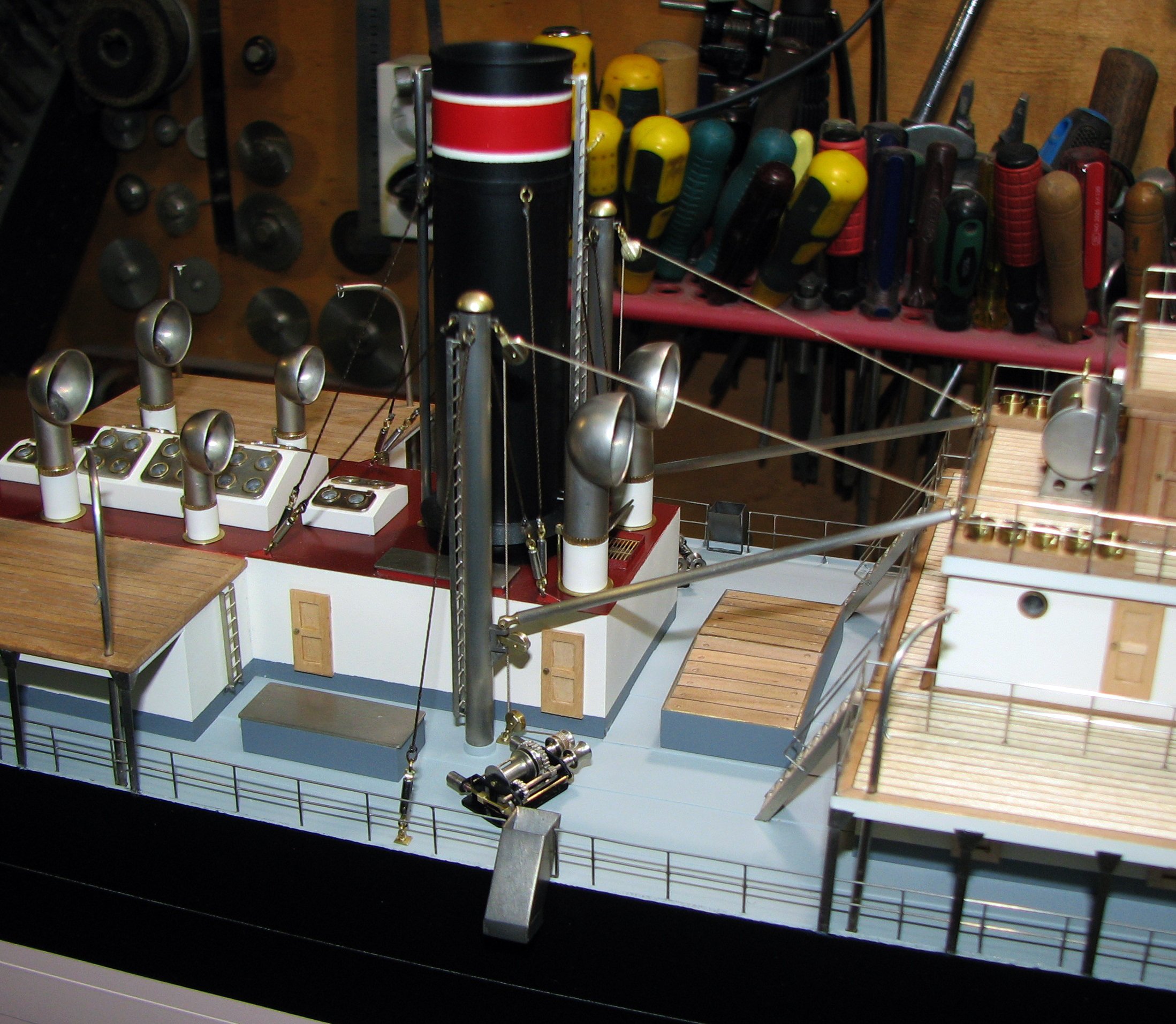
The photo shows the cargo device on the foremast.


-
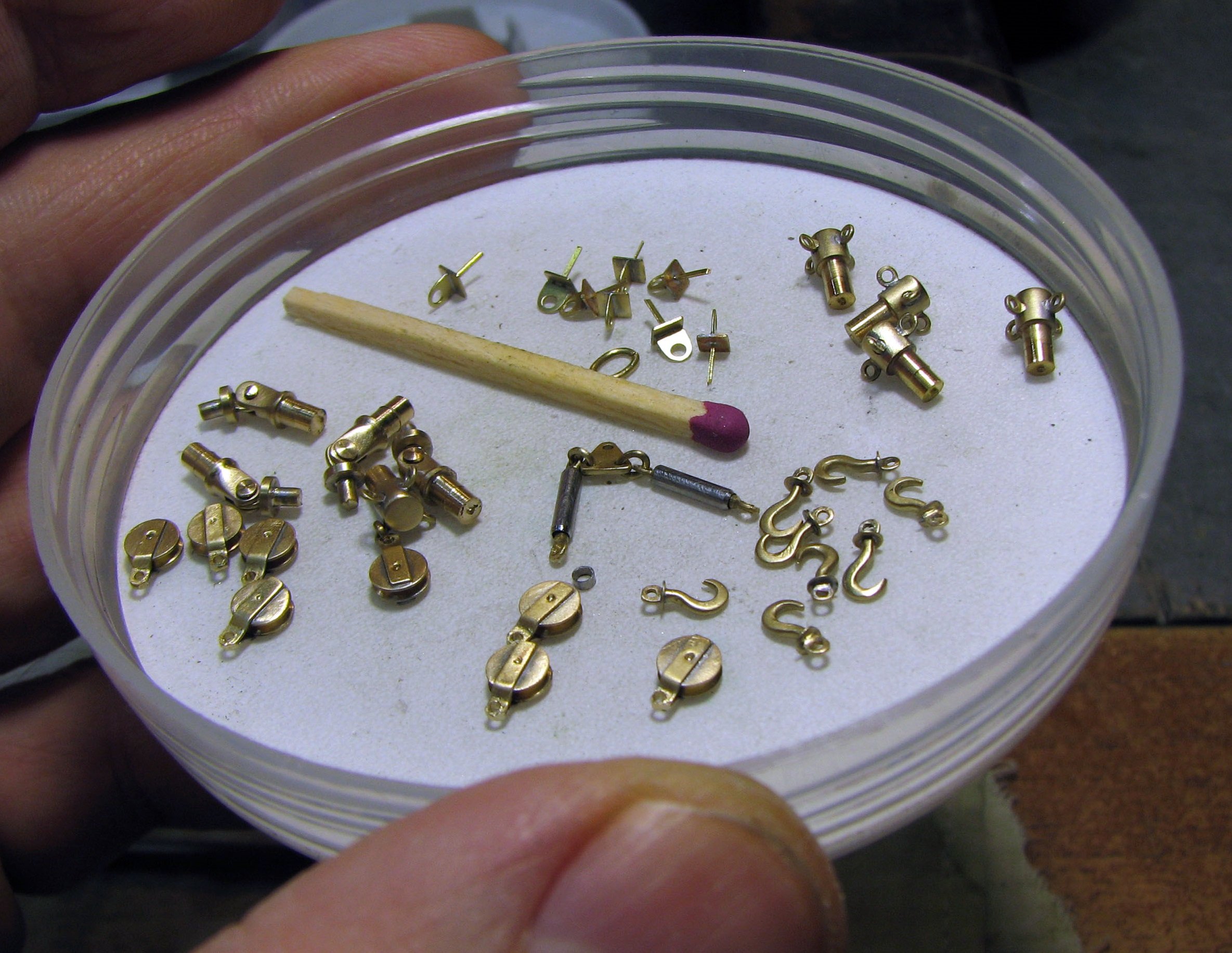
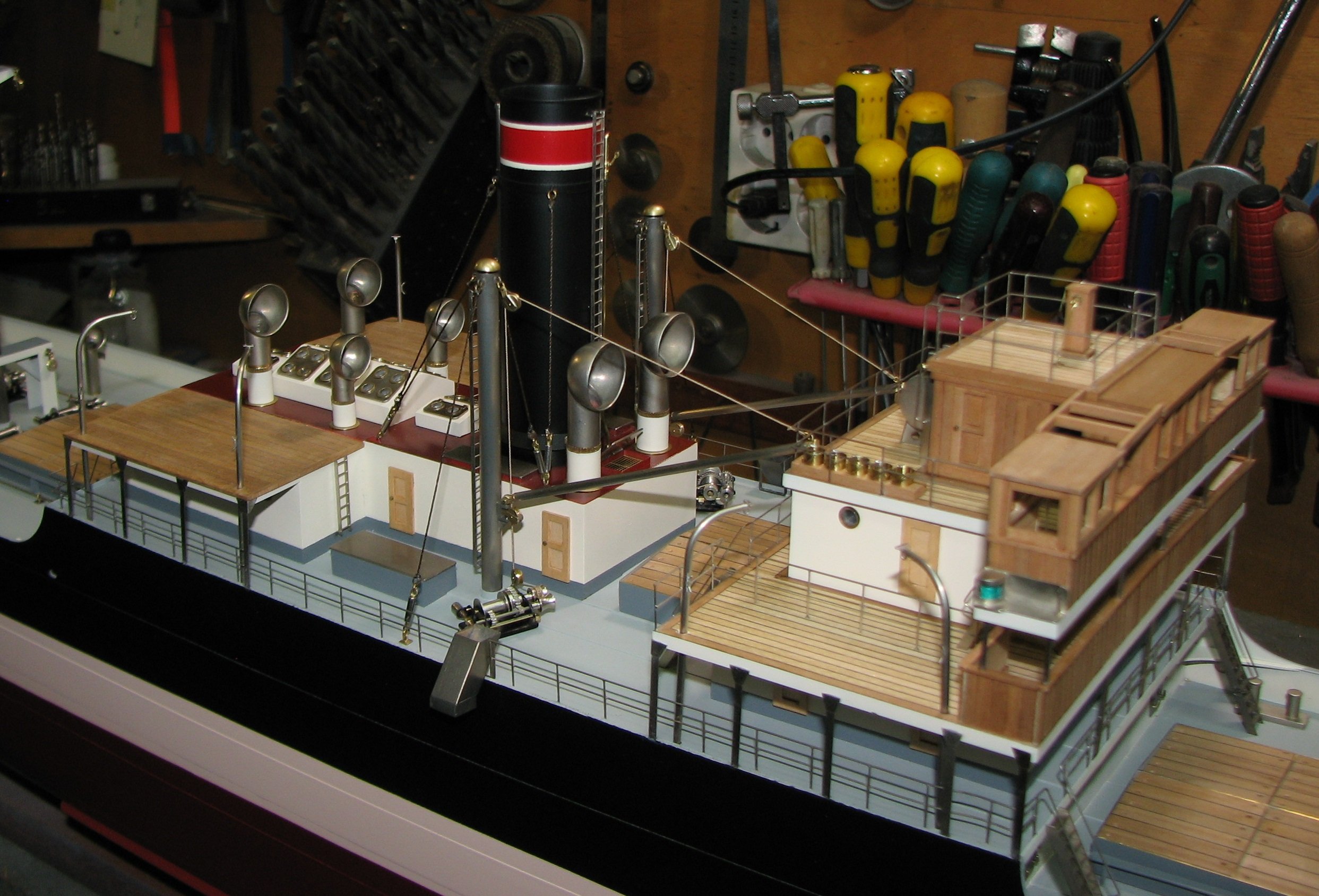
I greet everyone and thank you for your congratulations, likes and comments. I am pleased that my small model arouses interest among grateful viewers of my process. I move on to the stage of assembling small parts on the cargo device of the steamer.


-
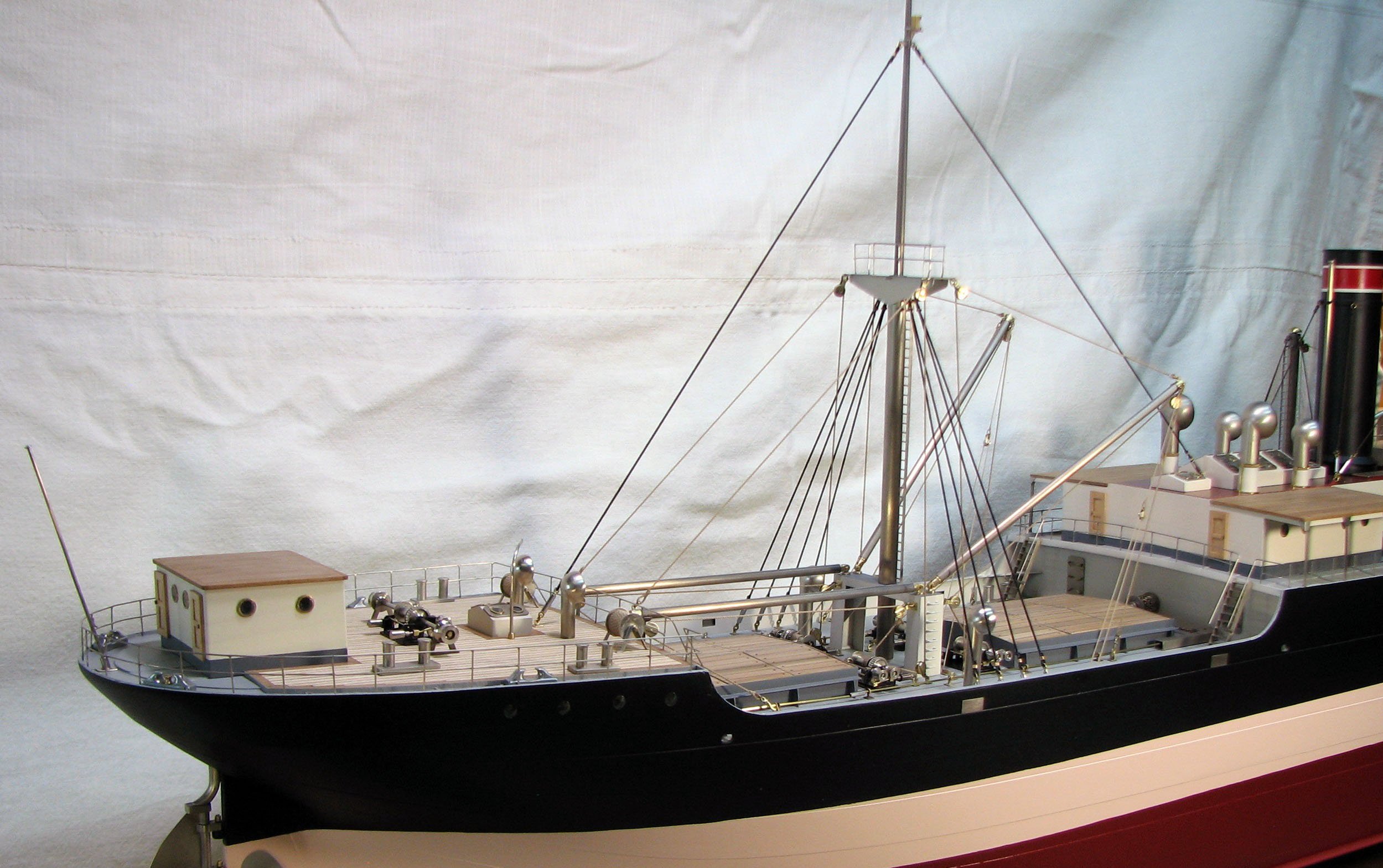
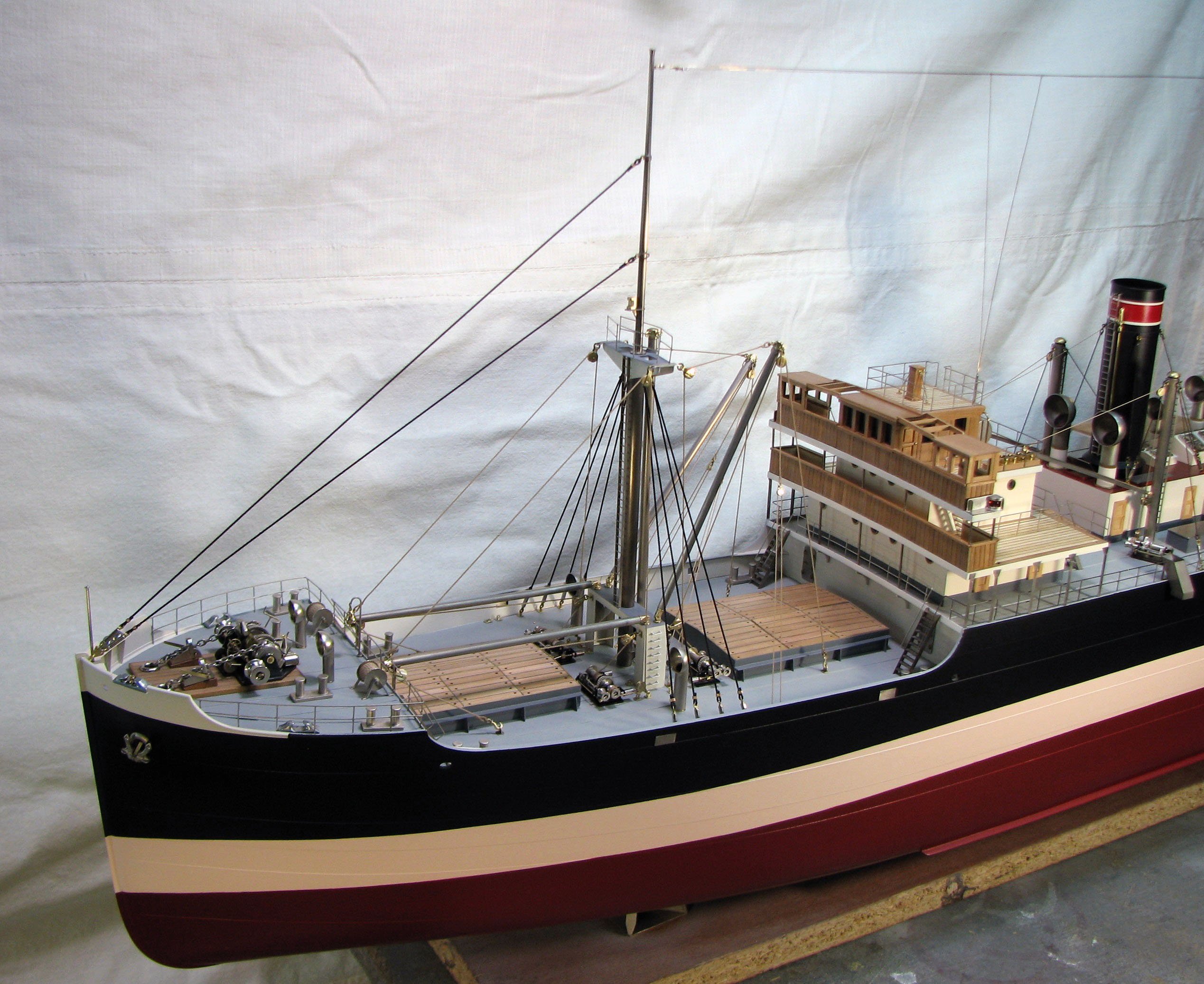
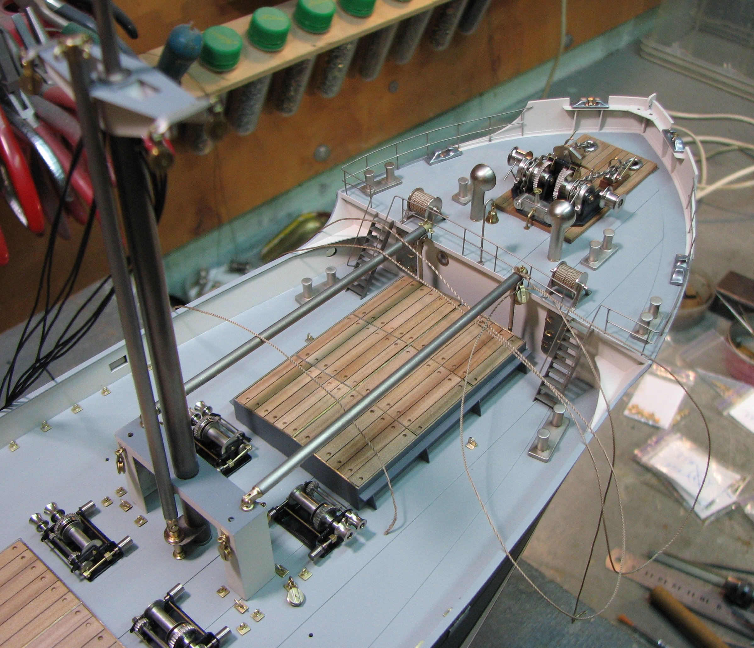
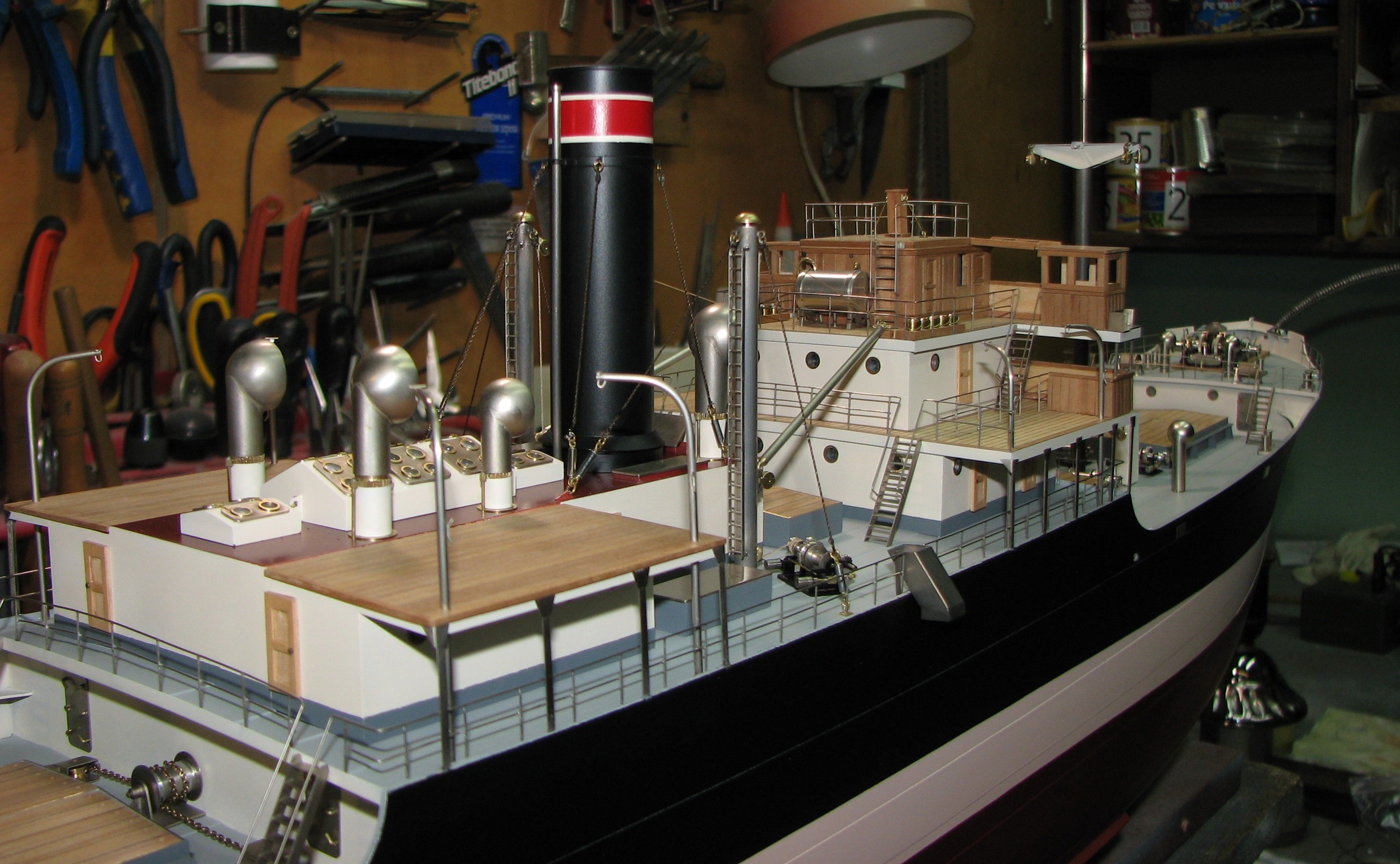
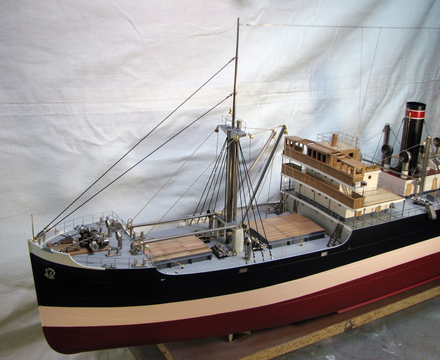
I welcome everyone to the new year! Installation of cargo handling equipment for holds No. 1 and No. 2
-
Thank you, Keith, for your congratulations! I also congratulate all forum members on the New Year holidays! And I wish everyone a good mood and success in building models!
-
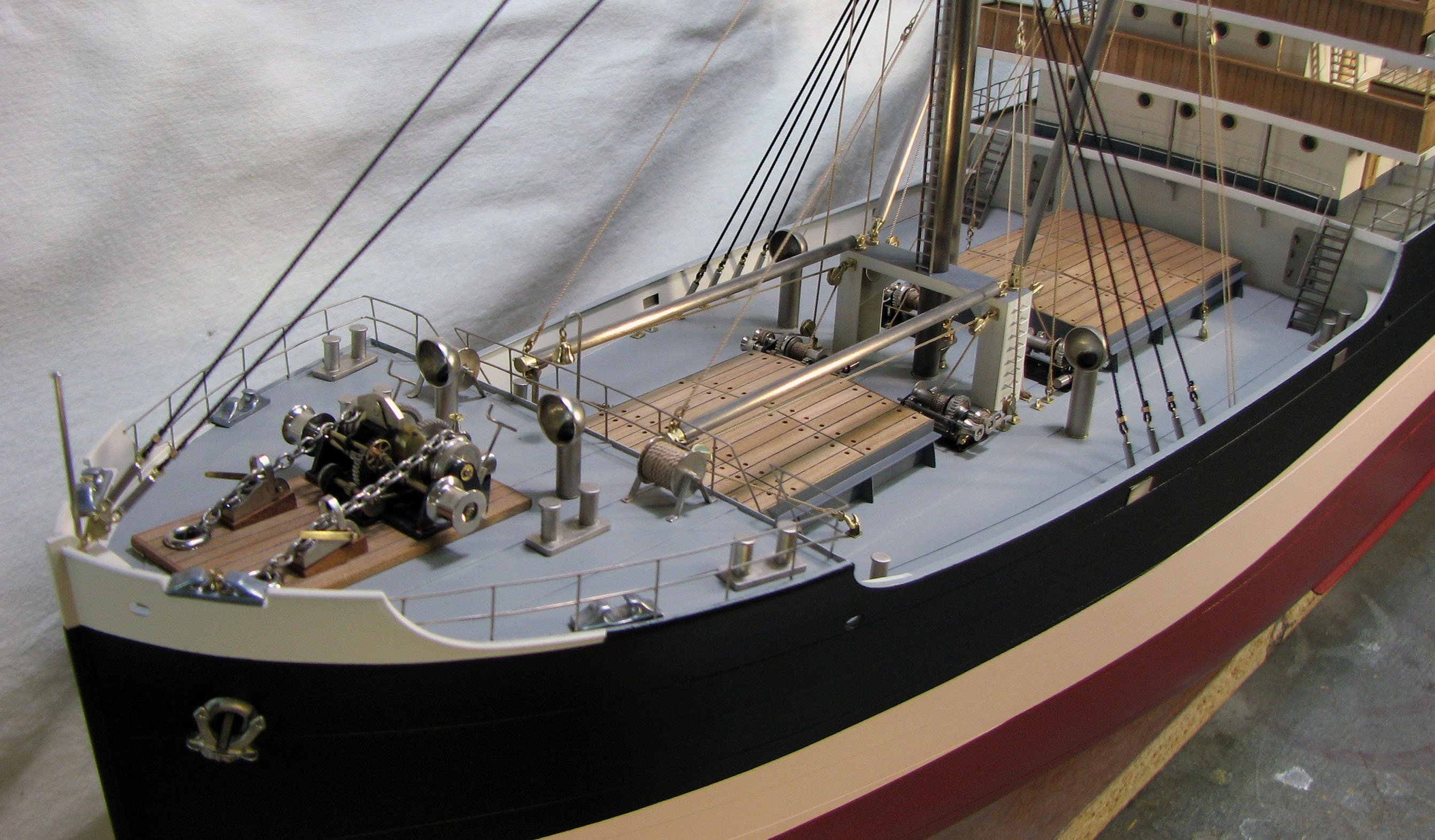
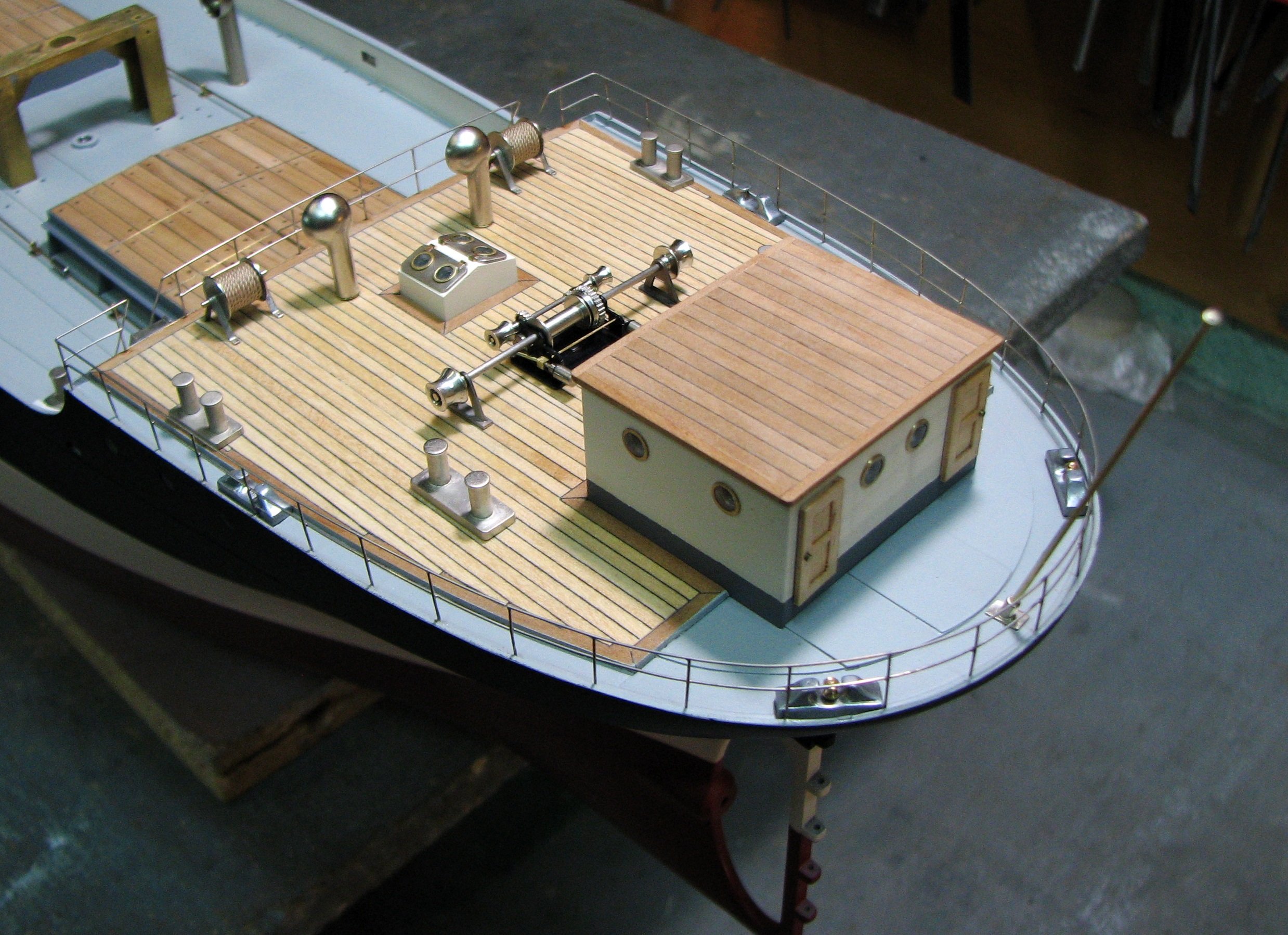
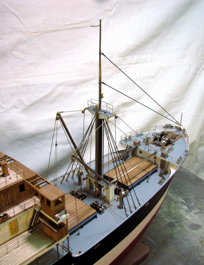
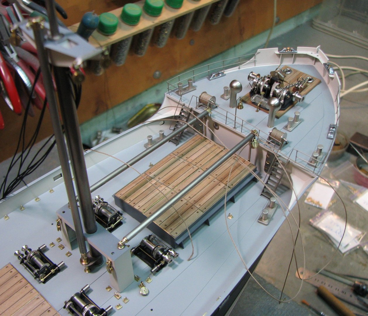
I continue to assemble the cargo device parts on the ship's spar deck.


-
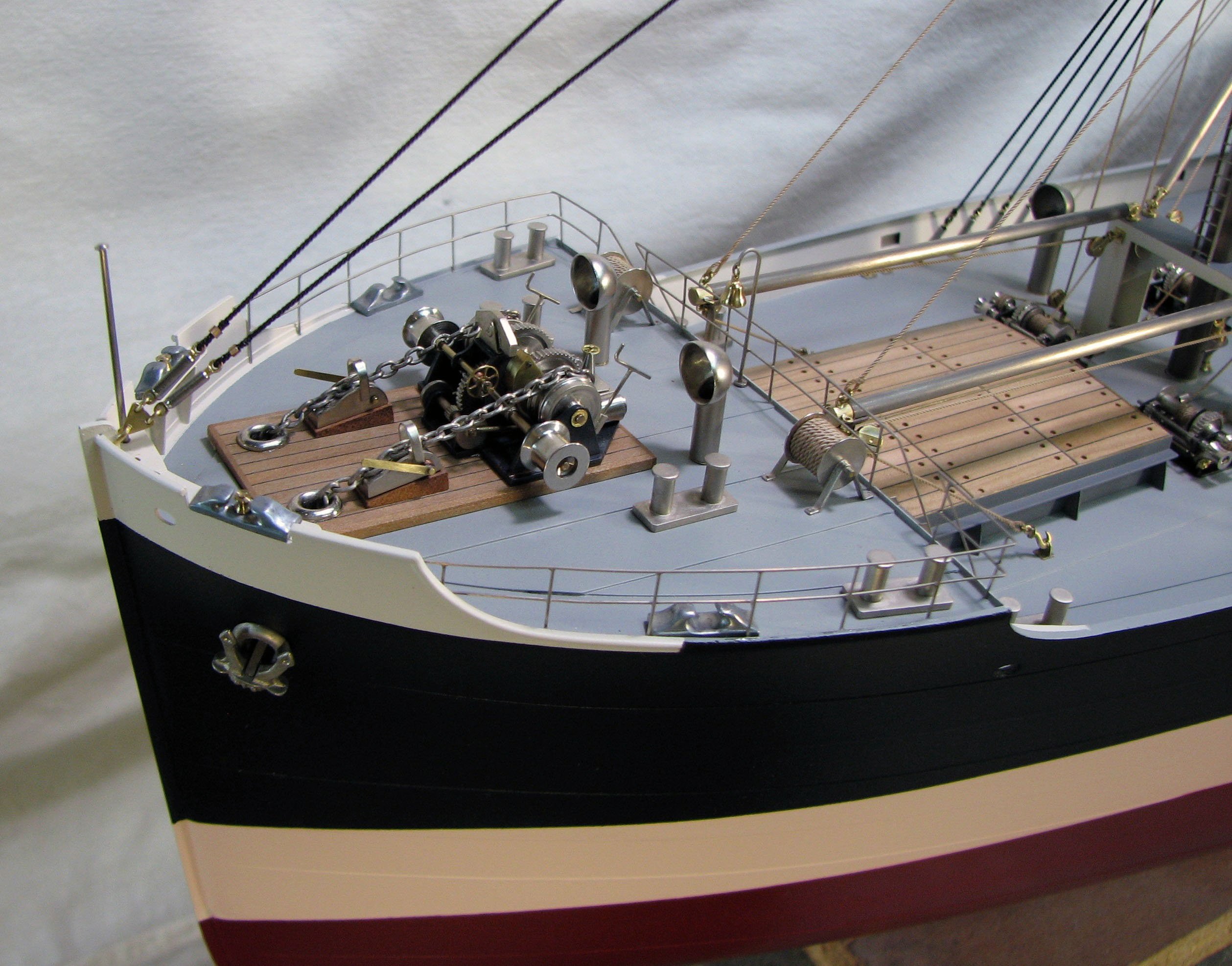
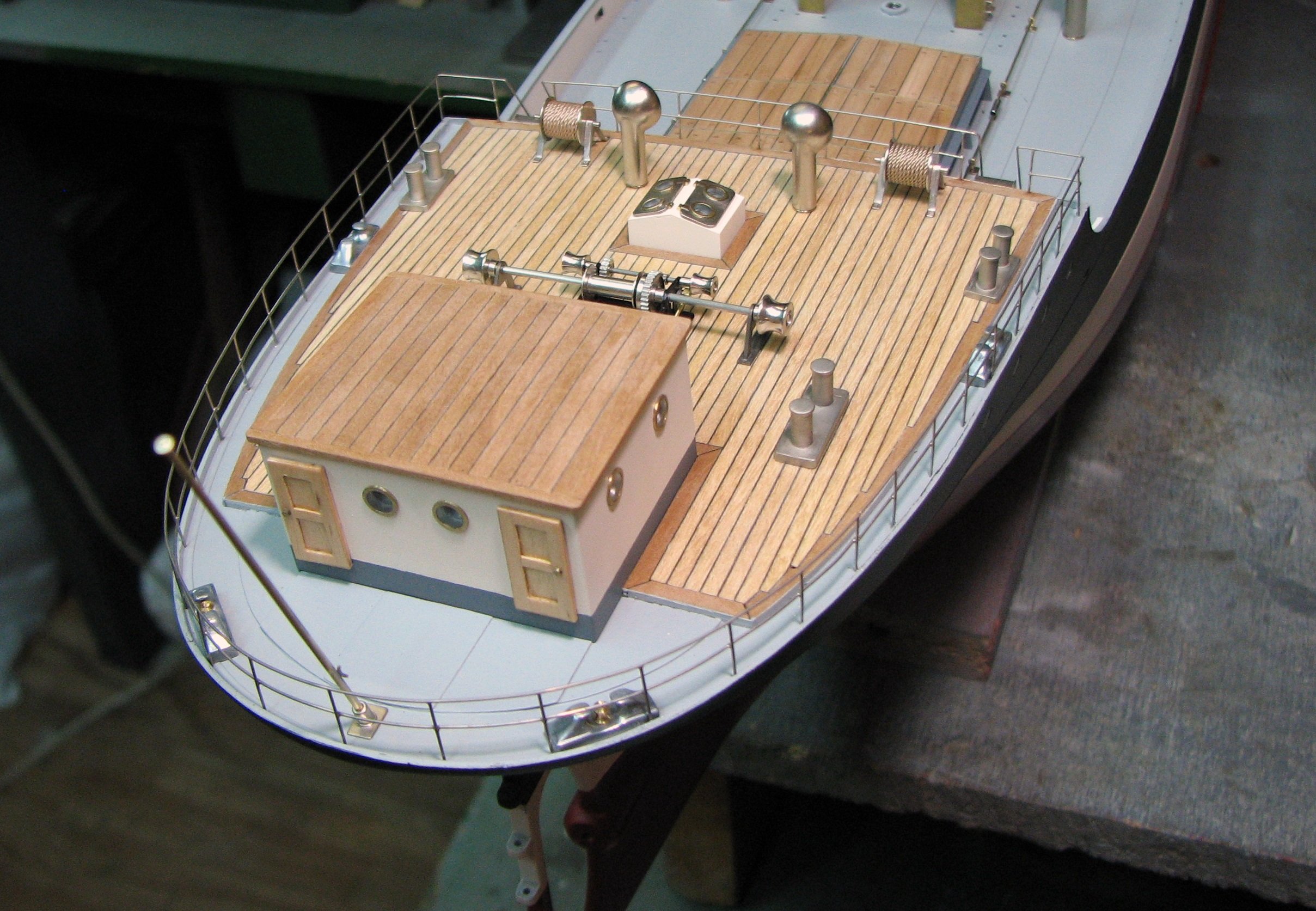
Thank you, Nils! The railings are soldered from brass wire with a diameter of 0.4 mm and coated with nickel. Holes with a diameter of 0.6 mm are drilled in the deck. Then the guard railings are put in place with cyanoacrylate glue.
-
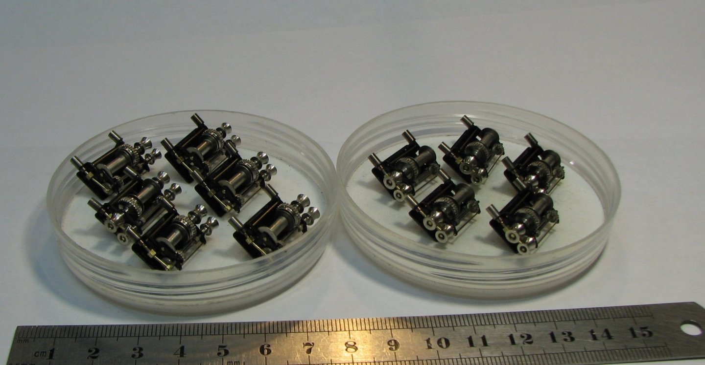
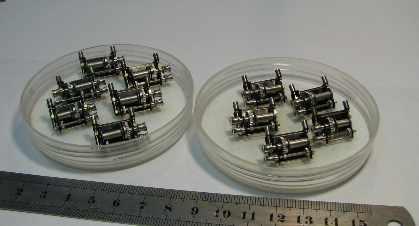
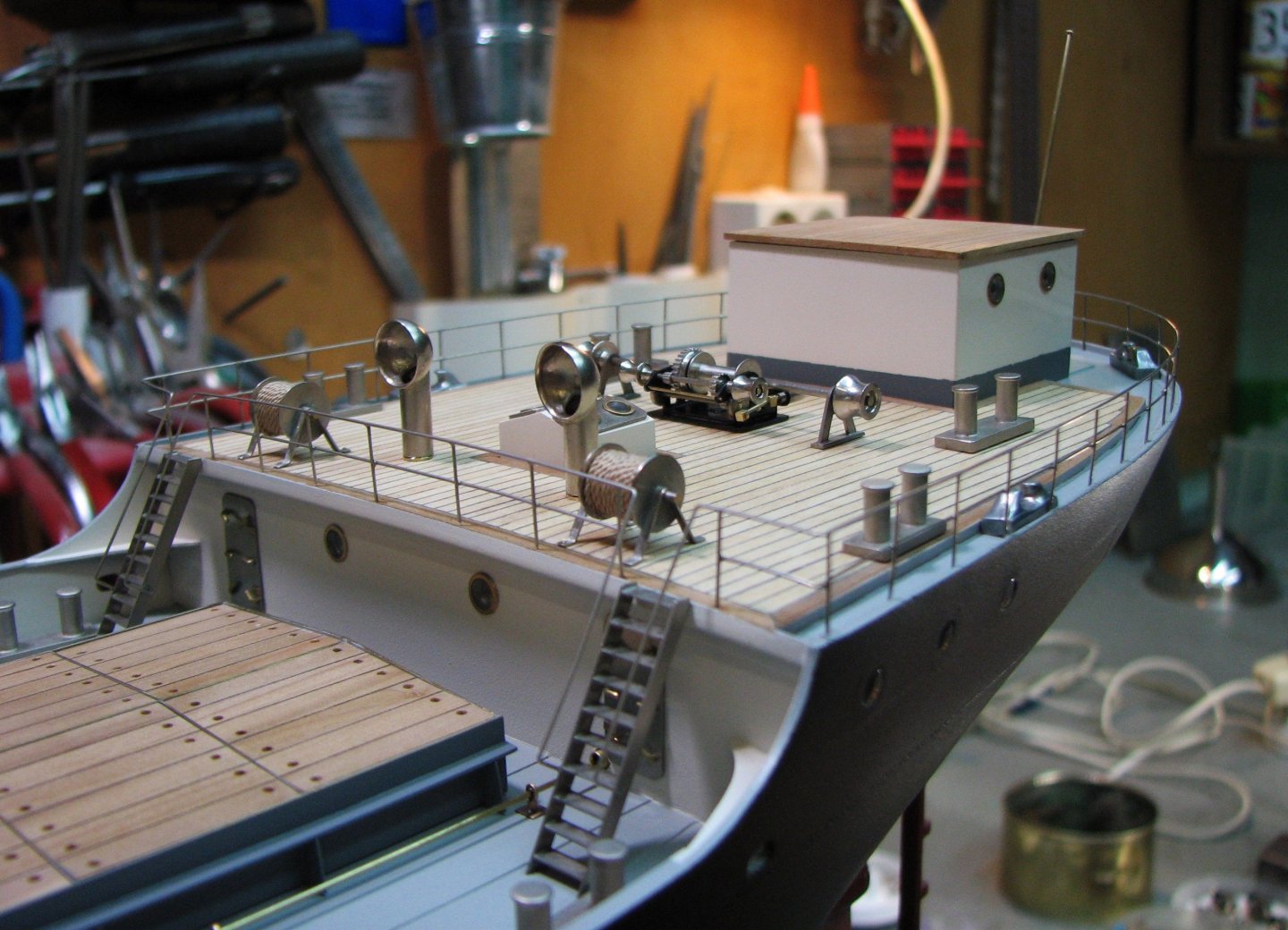
A steam winch for mooring is installed on the poop deck.


-
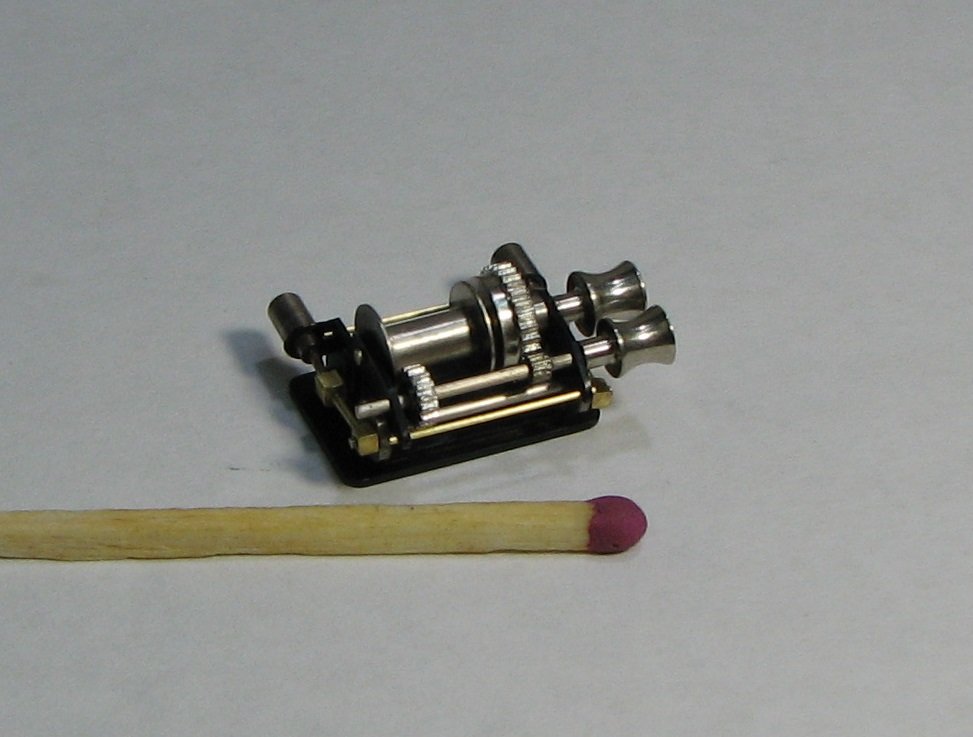
And finally, the traditional photo with a match.
-
Group photo.