jpalmer1970
-
Posts
408 -
Joined
-
Last visited
1 Follower
About jpalmer1970

Recent Profile Visitors
2,844 profile views


-
 jpalmer1970 reacted to a post in a topic:
Erycina 1882 by Blue Ensign - Vanguard Models - 1:64 scale - Plymouth Trawler
jpalmer1970 reacted to a post in a topic:
Erycina 1882 by Blue Ensign - Vanguard Models - 1:64 scale - Plymouth Trawler
-
jpalmer1970 reacted to a post in a topic:
Chris Watton and Vanguard Models news and updates Volume 2
-
jpalmer1970 reacted to a post in a topic:
HMS Crocodile 1781 by Pirate adam - 1/48 scale - POF
-
jpalmer1970 reacted to a post in a topic:
Erycina 1882 by Blue Ensign - Vanguard Models - 1:64 scale - Plymouth Trawler
-
jpalmer1970 reacted to a post in a topic:
Erycina 1882 by Blue Ensign - Vanguard Models - 1:64 scale - Plymouth Trawler
-
jpalmer1970 reacted to a post in a topic:
Chris Watton and Vanguard Models news and updates Volume 2
-
jpalmer1970 reacted to a post in a topic:
Chris Watton and Vanguard Models news and updates Volume 2
-
jpalmer1970 reacted to a post in a topic:
HMS Thorn by Kevin Kenny - 1:48 scale - Swan-class - David Antscherl practium
-
jpalmer1970 reacted to a post in a topic:
Erycina 1882 by Blue Ensign - Vanguard Models - 1:64 scale - Plymouth Trawler
-
jpalmer1970 reacted to a post in a topic:
Erycina 1882 by Blue Ensign - Vanguard Models - 1:64 scale - Plymouth Trawler
-
druxey reacted to a post in a topic:
The Hayling Hoy by jpalmer1970 - 1:48 scale - First POF build
-
druxey reacted to a post in a topic:
The Hayling Hoy by jpalmer1970 - 1:48 scale - First POF build
-
CiscoH reacted to a post in a topic:
The Hayling Hoy by jpalmer1970 - 1:48 scale - First POF build
-
Stavanger reacted to a post in a topic:
The Hayling Hoy by jpalmer1970 - 1:48 scale - First POF build
-
 marsalv reacted to a post in a topic:
The Hayling Hoy by jpalmer1970 - 1:48 scale - First POF build
marsalv reacted to a post in a topic:
The Hayling Hoy by jpalmer1970 - 1:48 scale - First POF build
-
 Pirate adam reacted to a post in a topic:
HMS Crocodile 1781 by Pirate adam - 1/48 scale - POF
Pirate adam reacted to a post in a topic:
HMS Crocodile 1781 by Pirate adam - 1/48 scale - POF
-
Keith Black reacted to a post in a topic:
HMS Crocodile 1781 by Pirate adam - 1/48 scale - POF
-
 Looking very good, nice and clean and sharp. I am at a similar stage in my build and am finding it hard to be so exact. I suspect my present attempt at the hawser timbers will end up as a useful practice run 😀
 -
yvesvidal reacted to a post in a topic:
The Hayling Hoy by jpalmer1970 - 1:48 scale - First POF build
-
Boccherini reacted to a post in a topic:
The Hayling Hoy by jpalmer1970 - 1:48 scale - First POF build
-
Maxthebuilder reacted to a post in a topic:
The Hayling Hoy by jpalmer1970 - 1:48 scale - First POF build
-
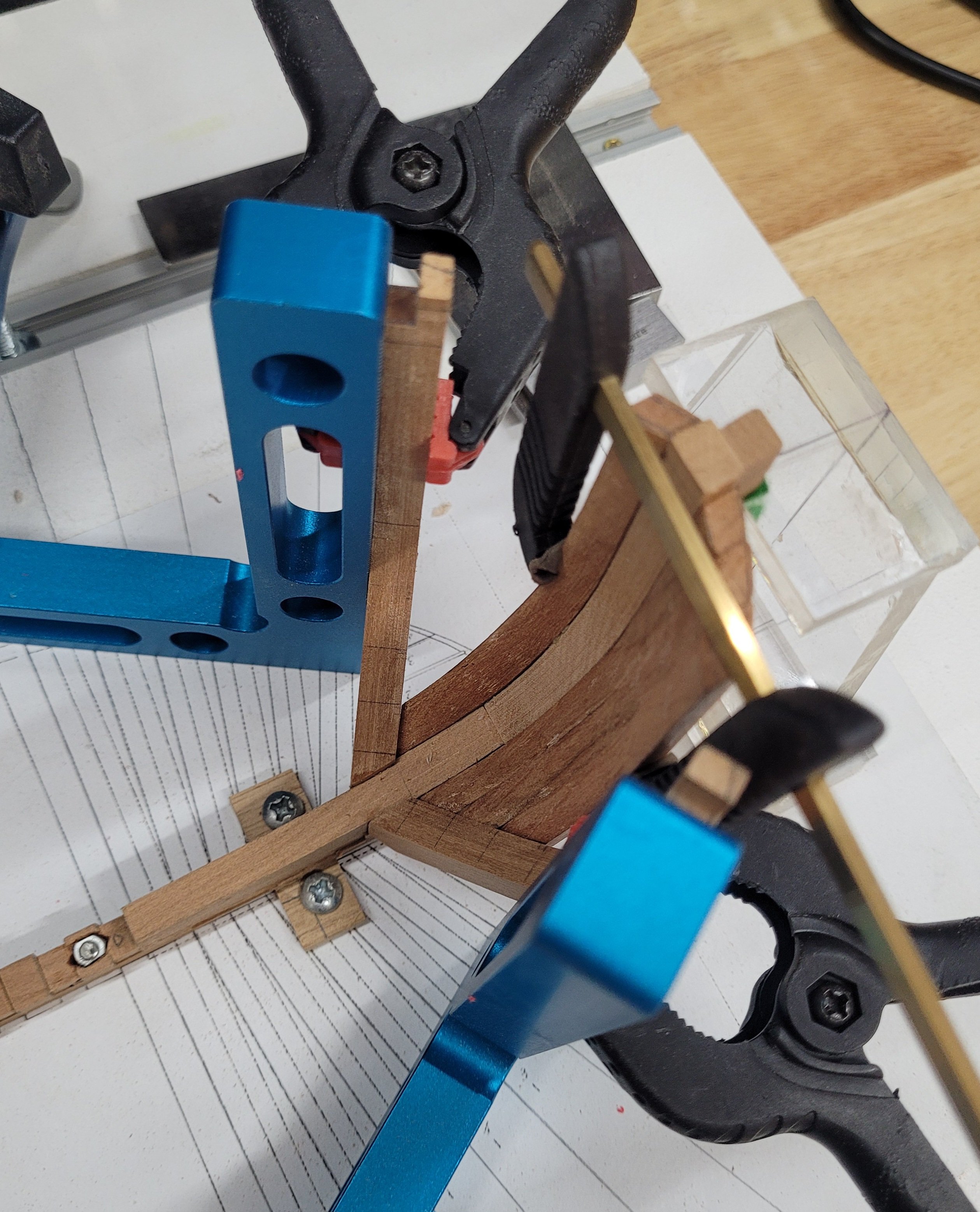
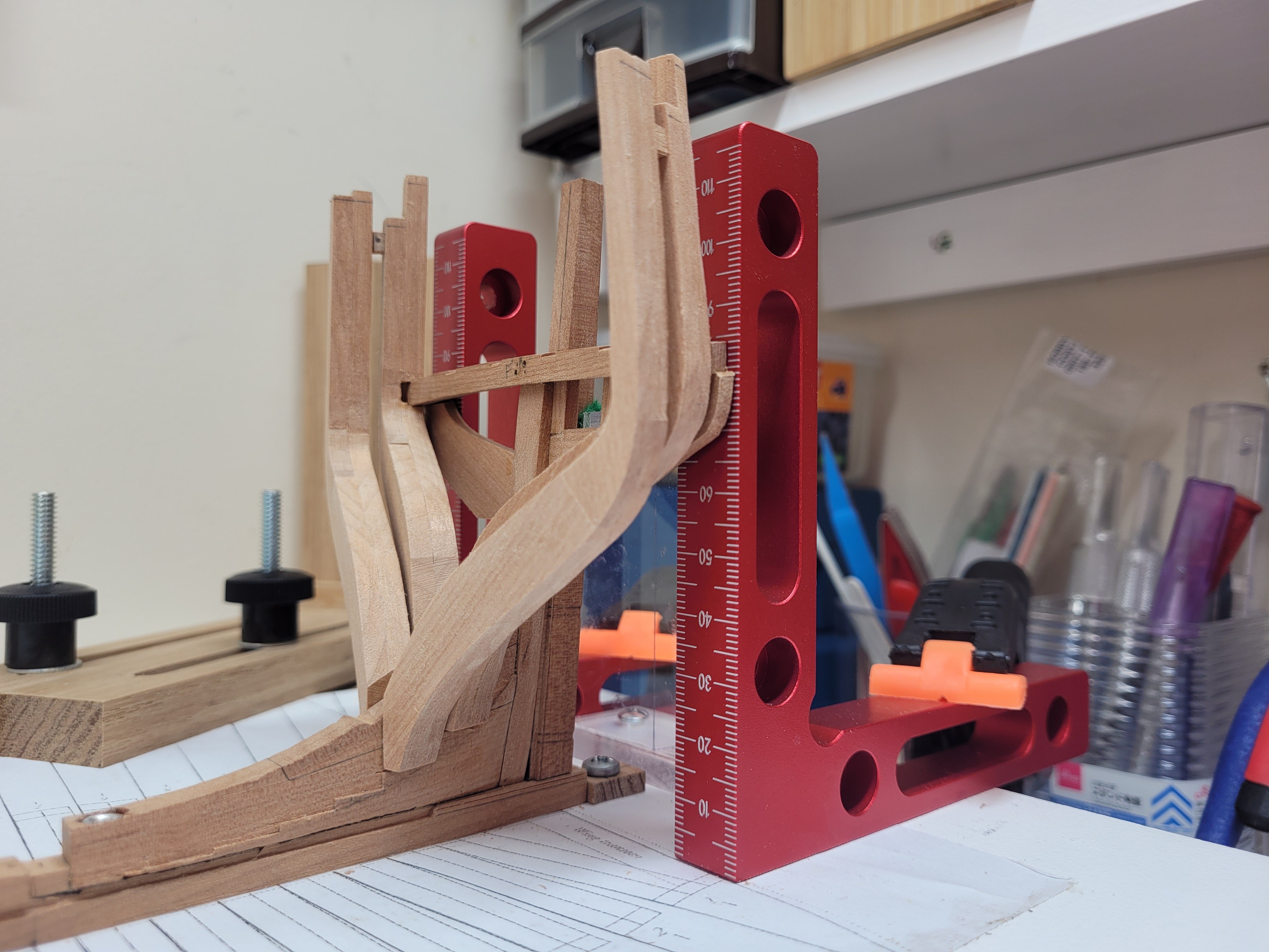
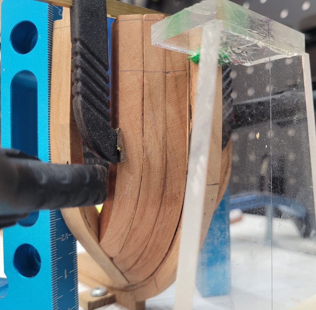
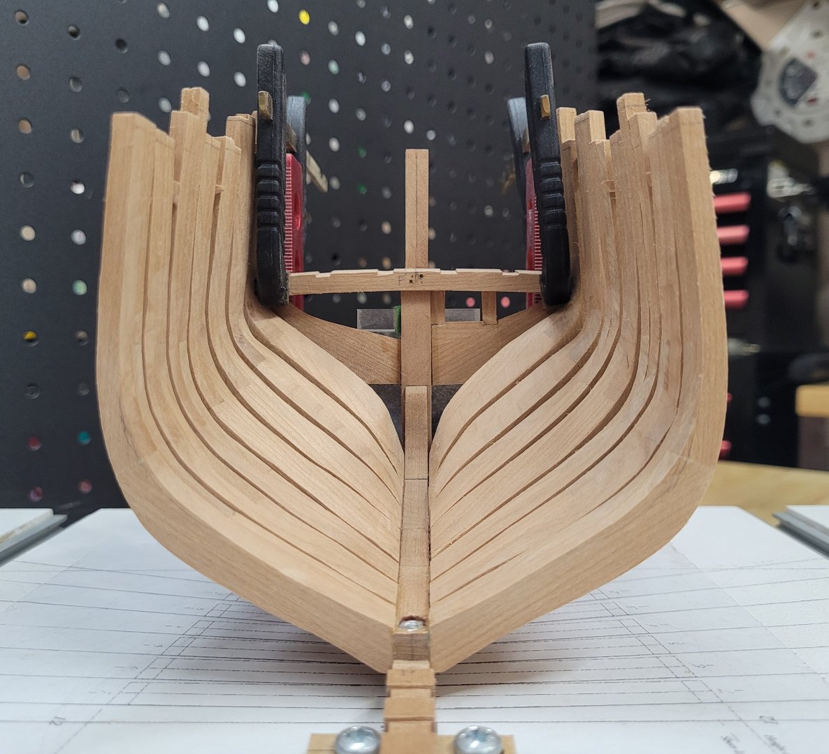
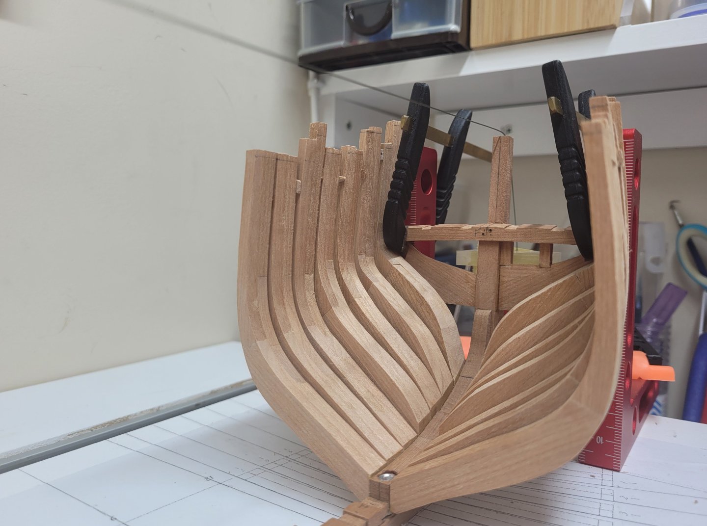
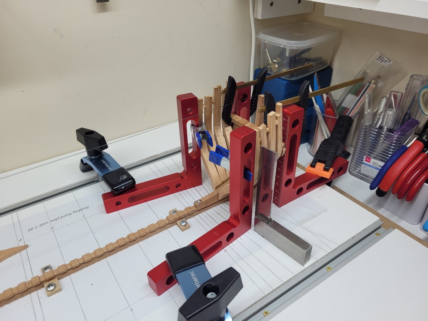
Hello again! Apologies for the lengthy delay in any update on this build. I had a couple months' absence from the model when various aspects of life got in the way and my free time seemed to disappear! Hopefully, I can now return to a bit more of a regular schedule. I restarted work by temporarily attaching the forward cant frame FC1 to the keel as this needs to be in place to ensure that the length of the bases of the bollard timbers and hawse pieces is correct. I then shaped the bevel on the inside face of the bollard timbers using my tilting table on the drill press sander. This worked pretty well on those areas where the bevel was consistent but I also resorted to some freehand sanding with a small drum in a dremel where there was a transition in the bevel angle. A similar procedure was also undertaken with the several hawse pieces which had also been cut from stock on the scroll saw. The bollard timbers were temporarily spot glued to the stem and the hawse pieces then spot glued to the bollard timber. This is the state of progress so far with further hawse pieces still to be added. I have left the inner and outer faces to the bollard timber and hawse pieces slightly over size at present. They will be removed from the stem in due course and sanded to a smoother curve as a single unit. You may note that the base of one of the hawse pieces doesn't quite match up to the cant frame but that shouldn't be a problem as there also needs to be a bevel faired into the foreside of the cant frame and the base of the hawse pieces in due course once the whole assembly has been completed (you can see the line marked on the can't frame to indicate this). If it does prove to be a problem then I can have another attempt at it again (as I would be surprised if things go exactly to plan first time around!).

- 92 replies
-
- 18
-
-
-
Welcome!
-
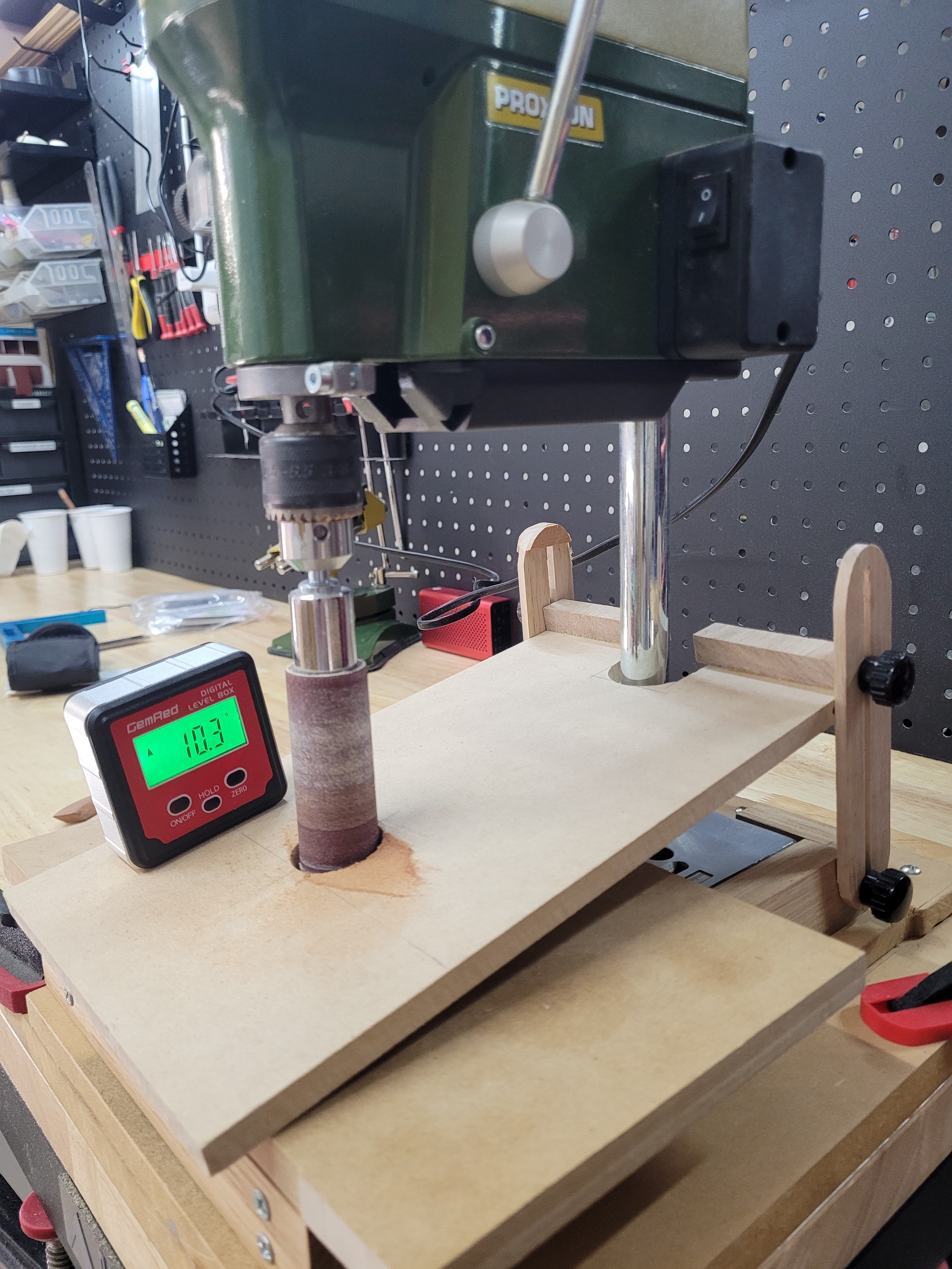
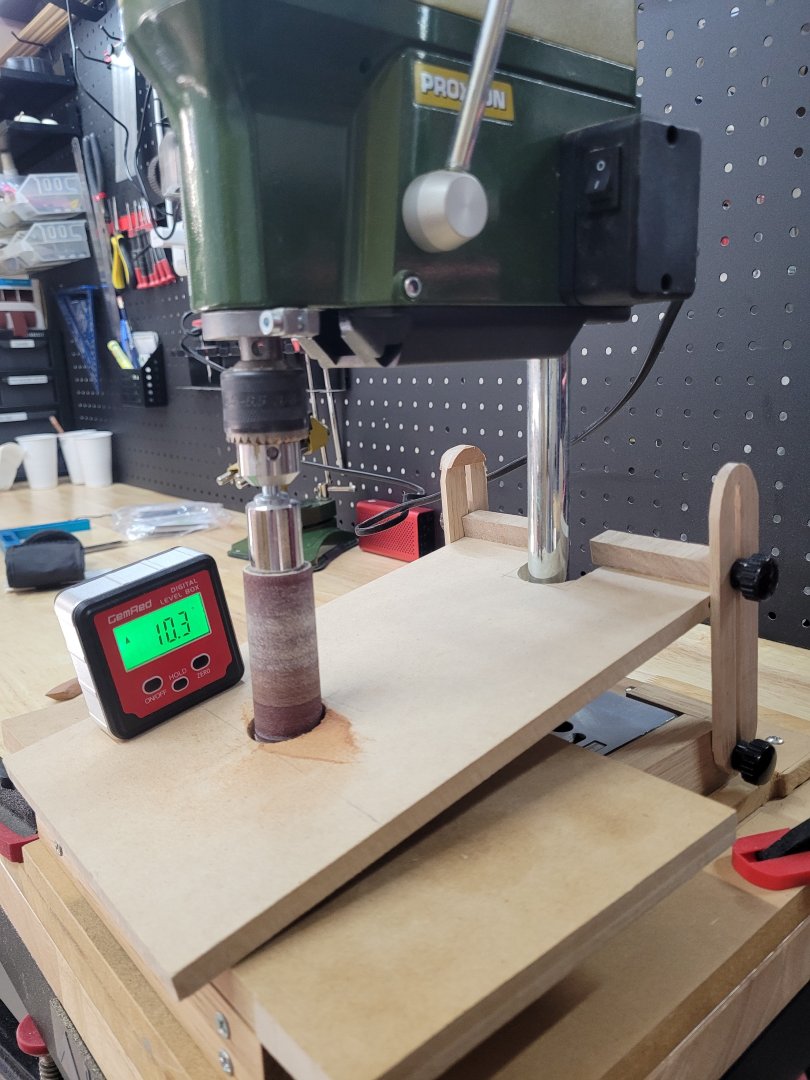
Hello, Only a brief update this time as not much has happened with the build itself of late. I have been considering the best way to shape bevel on the internal curve of the bollard timbers and hawse pieces and decided that a tilting table for my spindle sander/drill press would be a good idea, so I have spent some time making this. It is just a piece of mdf with some screw in insert nuts attached which allows me to move it up and down on a hinge point which is attached to the sanding base. It is pretty cheap and cheerful but seems to get the work done as required, up to about 18 degrees or so. I intend to start work on bevelling the bollard timbers and hawse pieces shortly. I have also made up the pieces for the first forward cant frame as this needs to be temporarily fixed into place to determine the where the aft ends of the bollard timbers and hawse pieces finish. This has been constructed and the foot bevelled to the correct angle ready to mount to the keel with rubber cement.
- 92 replies
-
- 19
-
-
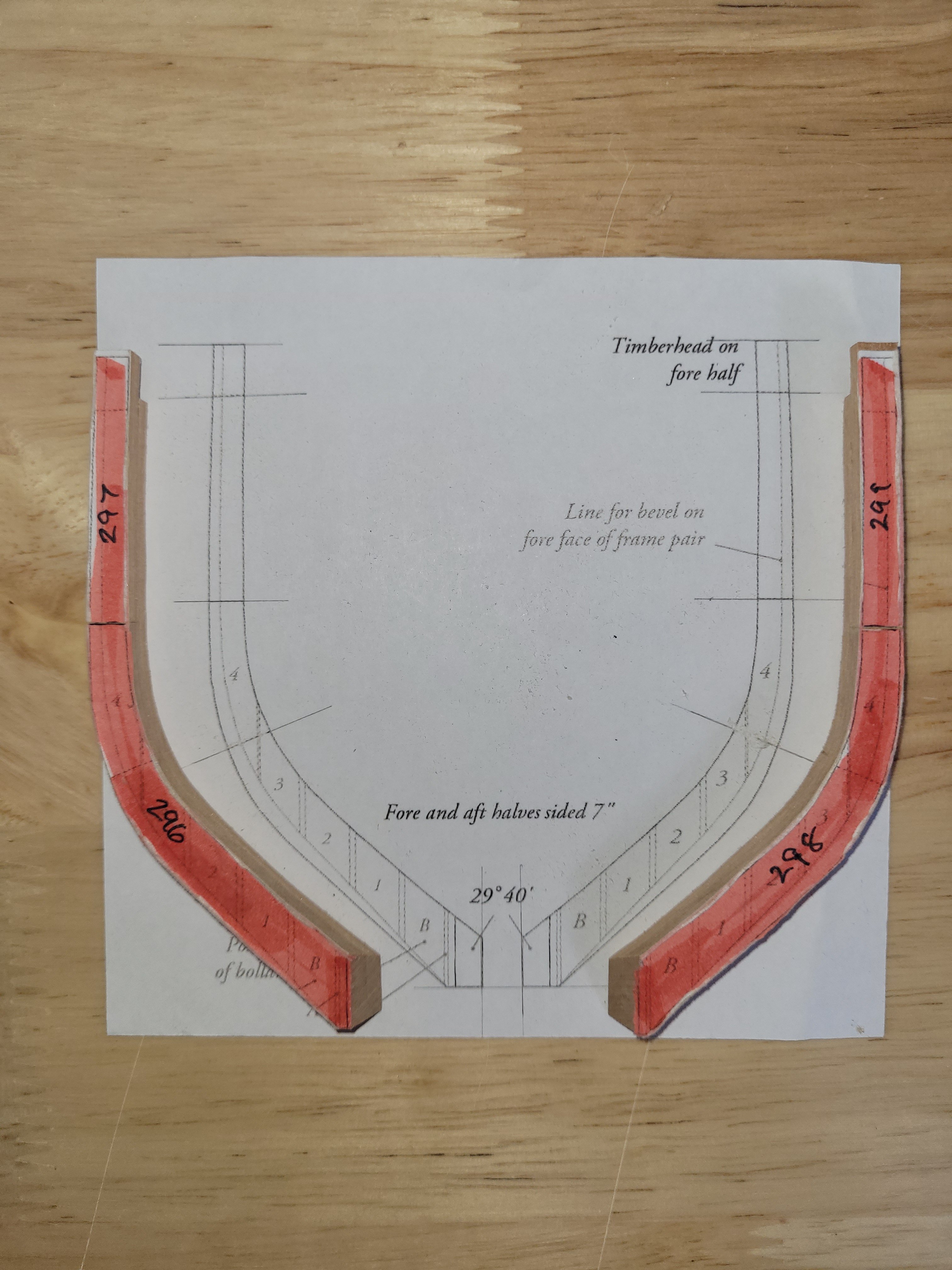
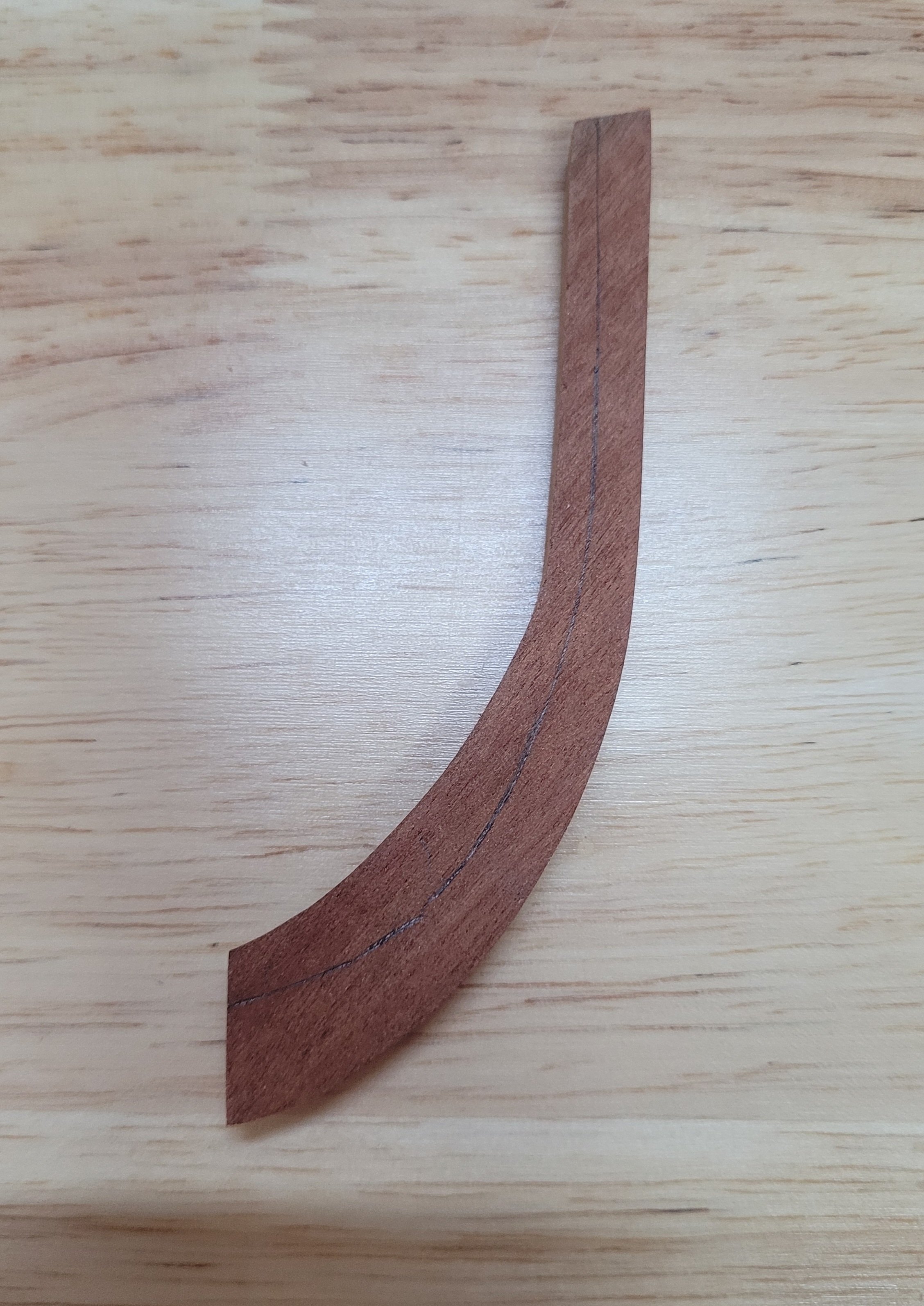
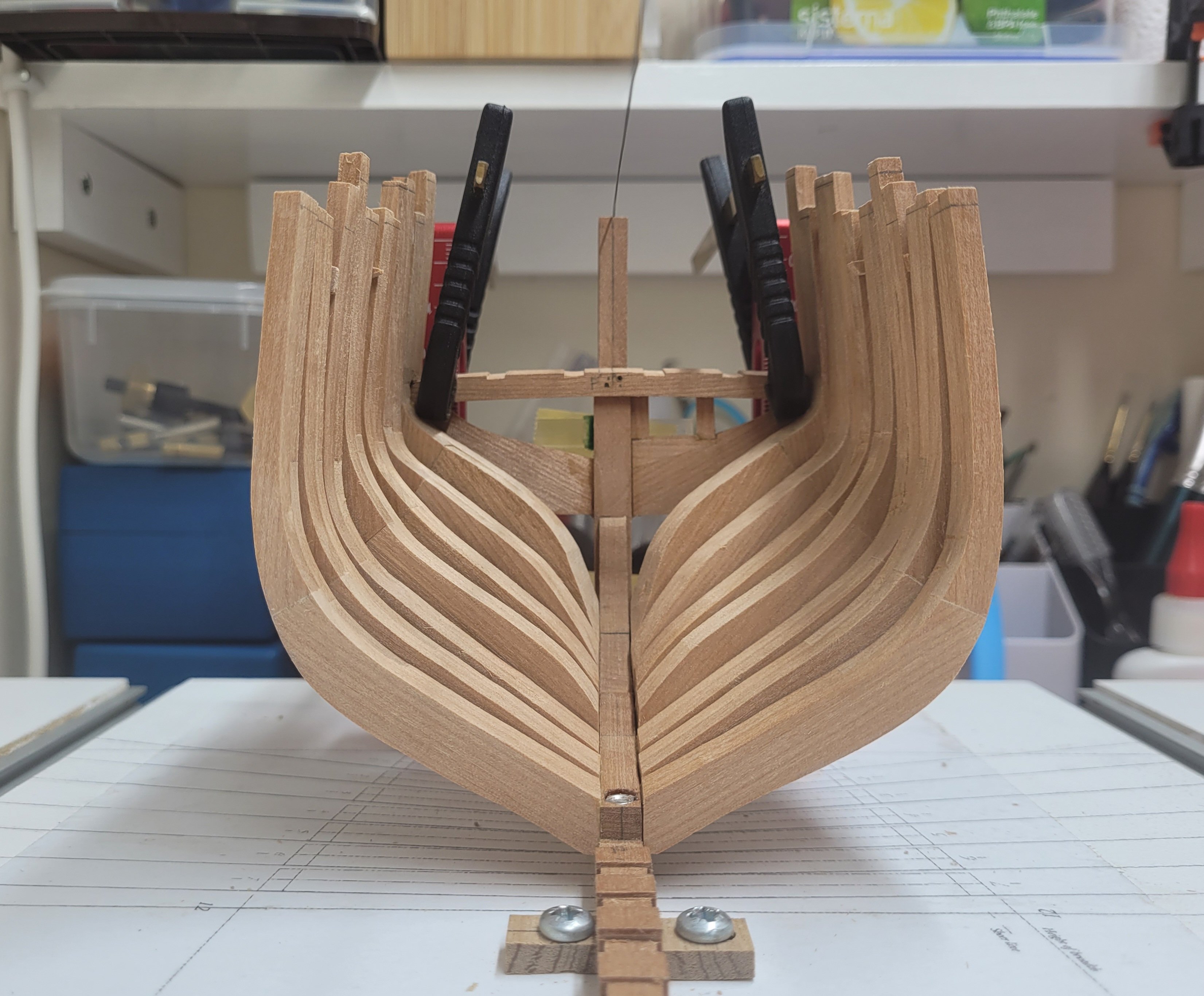
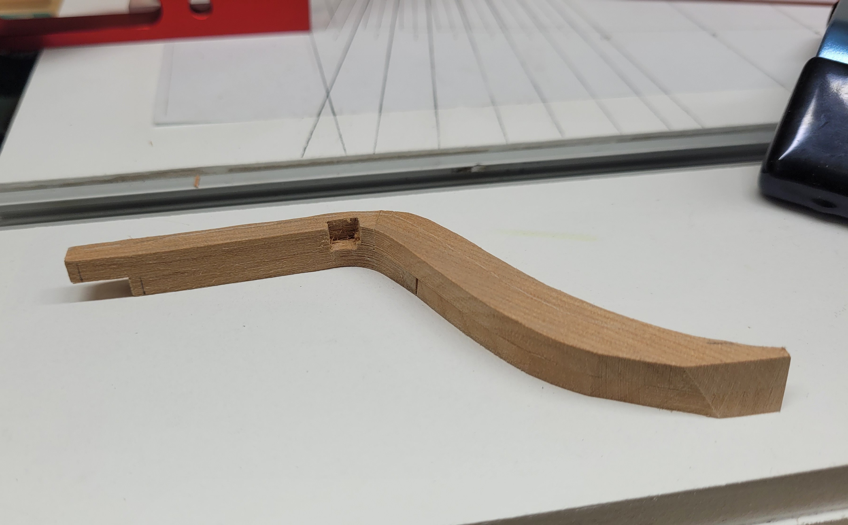
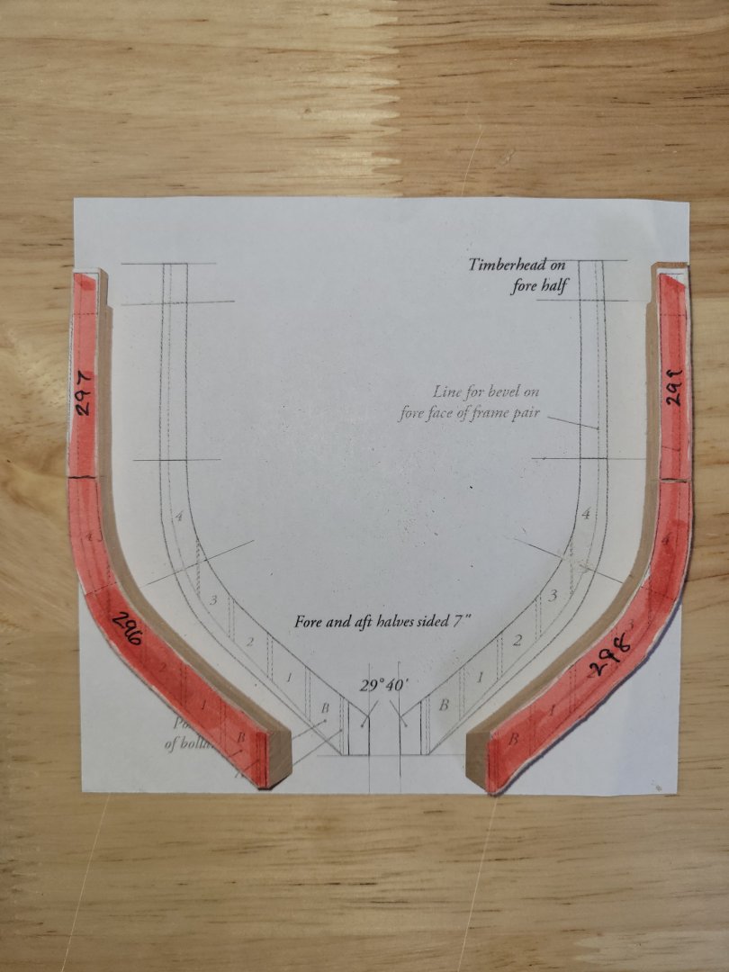
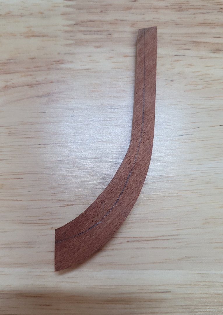
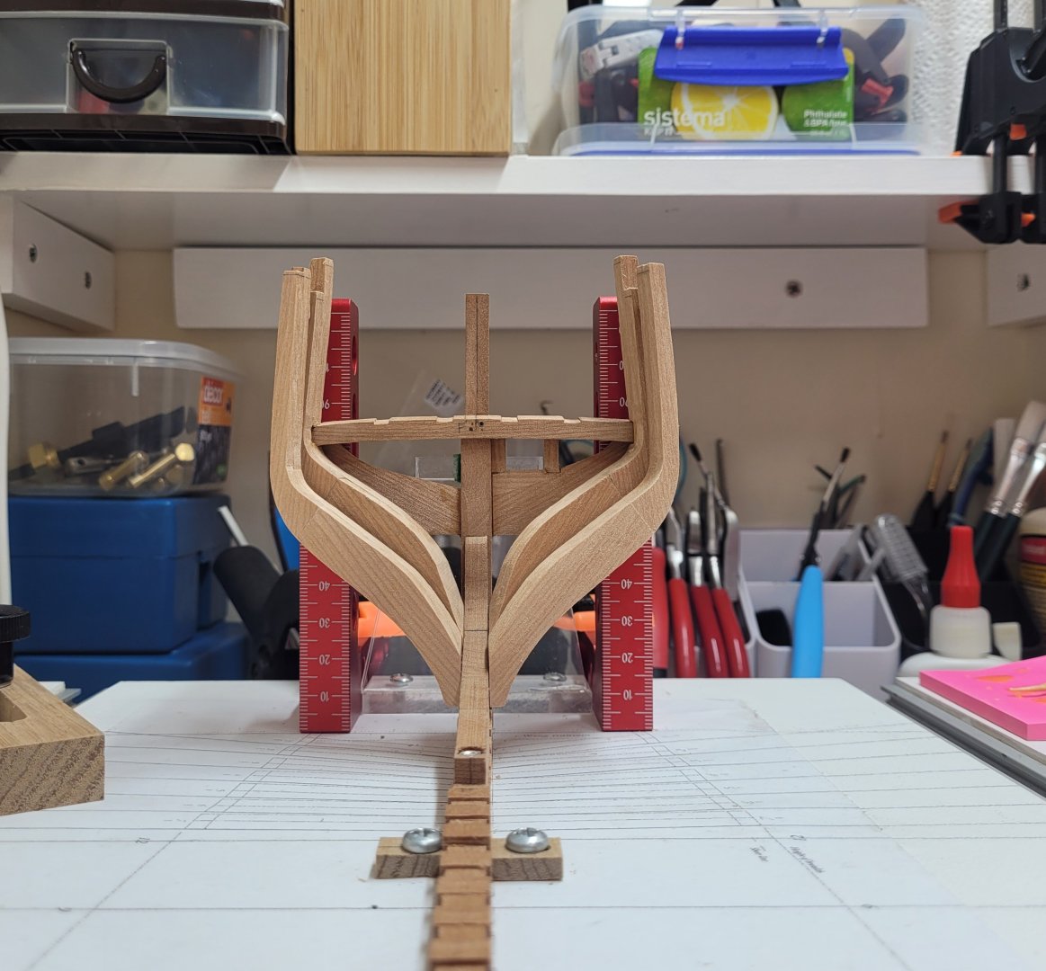
Work has continued on the sanding of the insides of the aft cant frames. I did my best to smooth out the rough sanding already undertaking on the starboard frames to try to make them as fair as I can at this stage. There will be more sanding needed in the future but I didn't want to go too far with that side just now as I though it best to try to get the port side frames to the same place so that things were symmetrical. Any further sanding that is required can then be undertaken on both sides at the same time. Here is where I got to with smoothing out the inner starboard aft cant frames. The port side frames were then sanded and smoothed to match as best I can. I am aware of the small undulations along the lengths of the frames and I will try to even these out in the near future before any final shaping to size. I've also spent some time with the bollard timbers which I had roughly cut out on the scroll saw some weeks ago. These need to have a quite significant bevel sanding into the outside curve as well as a bevel on the heel. I was able to sand these to shape using the disc sander - I have left them just a tad oversized on those faces at this time for final sanding in situ later. However, there is also a bevel required on the inside face - the line of which is taken off from the stemson. I have marked the line showing the extent of the bevel but haven't yet had chance to sand this face. The wood to the left of the line in the image below needs to be removed. To be honest, I am not sure of the best way to approach this. I have some sanding drums on the drill press but no tilt table. The bevel changes along the length of the piece and so perhaps I may need to make various angled wedges to try to orientate the bollard timber against the drum and sand it in stages starting from the smallest bevel to the largest?


- 92 replies
-
- 12
-
-
Very true. Even though everything is made from scratch, the worry of messing up a previously completed part and having to remake it again seems daunting. The chances are it may even be better next time around, but that doesn't seem to provide any comfort!
-
Indeed! I sometimes think it might be easier to make a full sized ship rather than a model! 😀
-
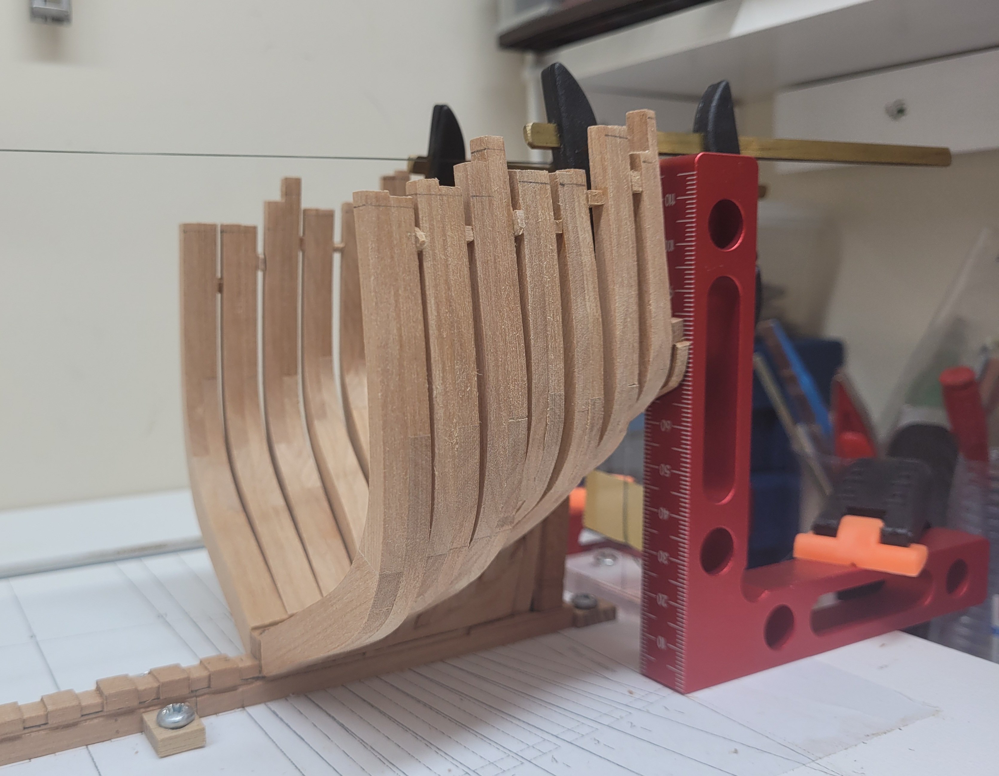
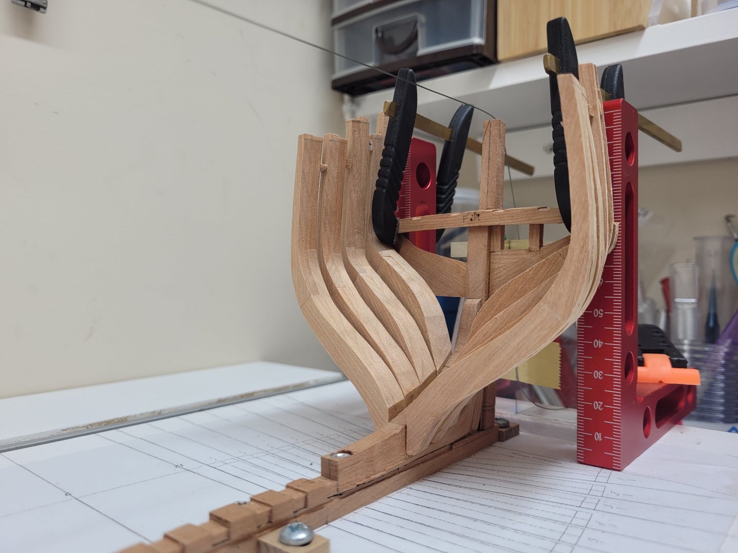
I finally found some time, and the courage (!), to make a proper start on the fairing of the inner aft cant frames. I was worried that these might be fairly fragile and that sanding could cause some problems but with the little filler bock holding the tops of the frames together the structure is remarkably strong. Even so, I took things quite slowly and sedately. I realise now that I should have really started the fairing much earlier, after every two or three frames perhaps. because I did find it difficult to get a tool or sanding stick into certain areas now that all of the aft cant frames are in place. I experimented with almost every sanding type tool I could find to see what worked best in this scenario, using dremels and a variety of sanding pads and discs, sanding sticks, home made sanding sticks, scrapers, riffler files, sanding blocks, and the Proxxon pen sander at one time or another! The little Dremel Lite and the flat sanding pad has done most of the work so far. I have only sanded one side of the model so far and this is just the first rough shaping. I don't want to take too much off too soon so I may just now focus on smoothing this side out out before tackling the other side to make sure they are symmetircal.

- 92 replies
-
- 14
-
-
Congratulations!
-
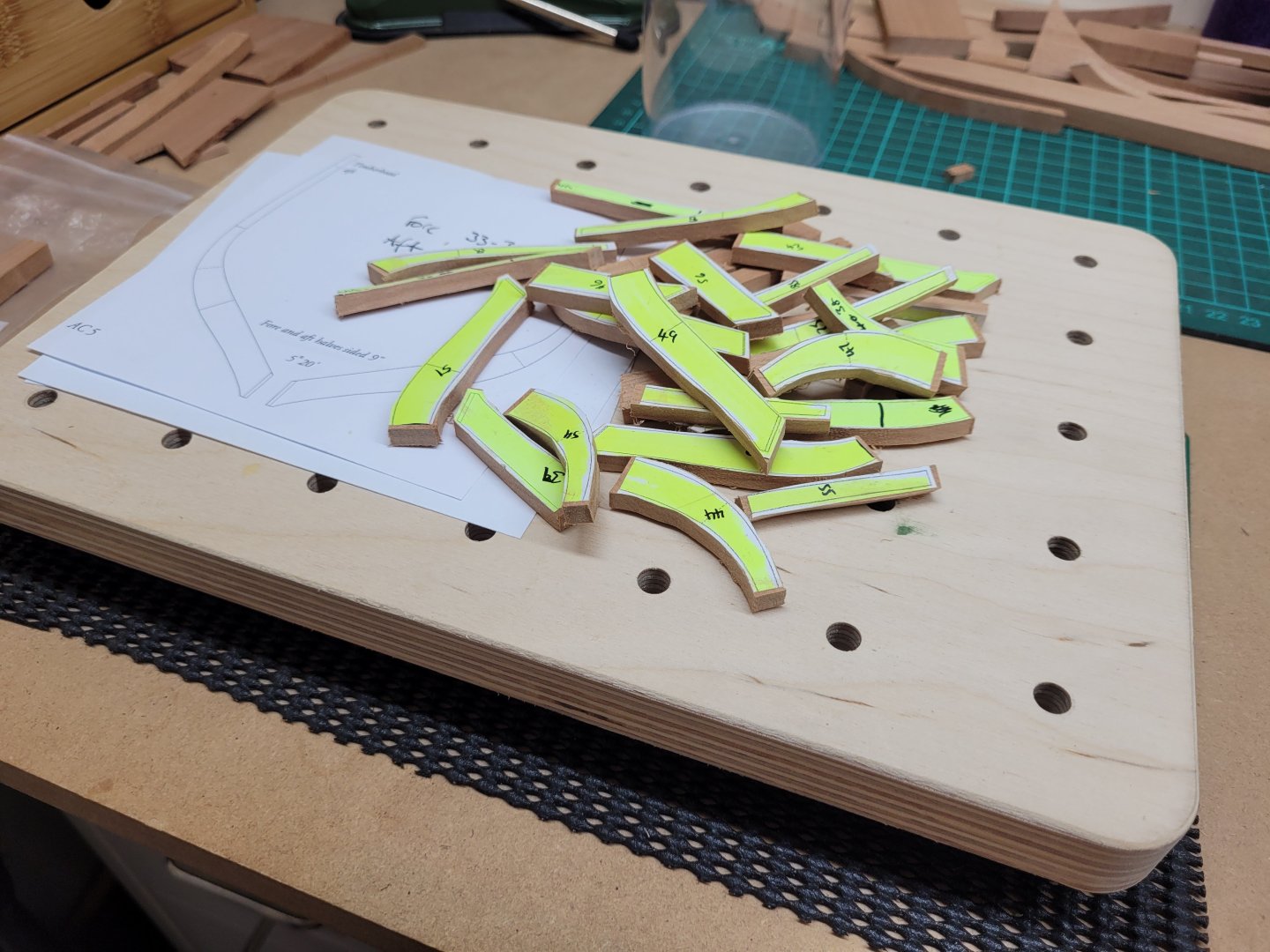
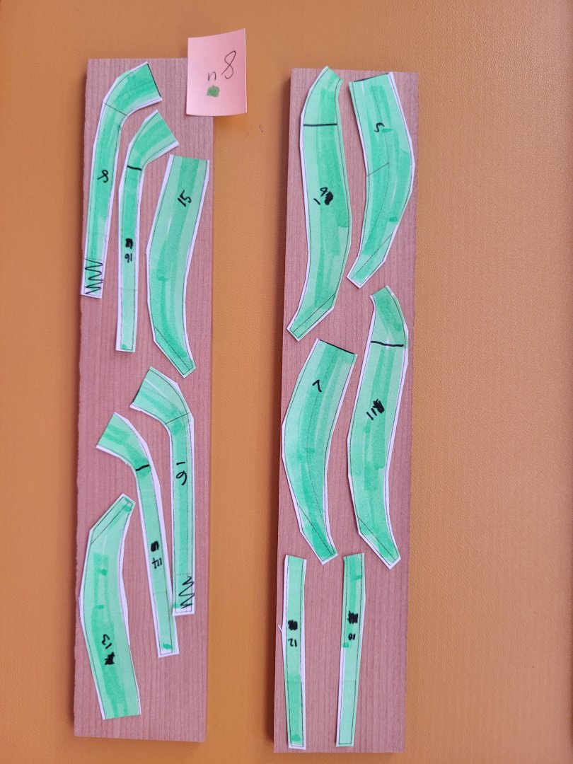
I have had a few weeks off from the build, firstly for a short holiday and then to completely reorganise my garage/workshop area so progress has been limited of late. Today I started work on the bollard timbers and hawse pieces. These have been cut out with the scroll saw on 12" stock and are now ready for shaping. I haven't made much progress with the sanding of the aft cant frames so far, so that is project that also needs to continue. I have been trying to work out the best way to approach this in regard to various shaped sanding blocks and tools. The Proxxon pen sander has been somewhat helpful and will probably be very useful later on for more finesse type work, but at the moment there is a lot of wood to remove and so I think I may need to resort to the riffler files etc to sort out the bulk of the material that needs to be taken away.

- 92 replies
-
- 12
-
-
Work has been continuing on the aft cant frames. I completed and installed the remaining three frames, frames AC5, AC6 and AC7. Next comes the rather daunting job of failing the insides of the frames. I note that @Stuntflyer marked the shape of the first square frame on the face of AC7 to give him an idea of where the guideline for fairing needs to be and so I think I will copy suit and do the same. I'll fair one side first rather than tackling them both at the same time. I have a range of shapes of soft sanders which I hope will help with the job. I also have a set of riffler files but I haven't used them before and am hesitant about whether they may be suitable?


- 92 replies
-
- 18
-
-
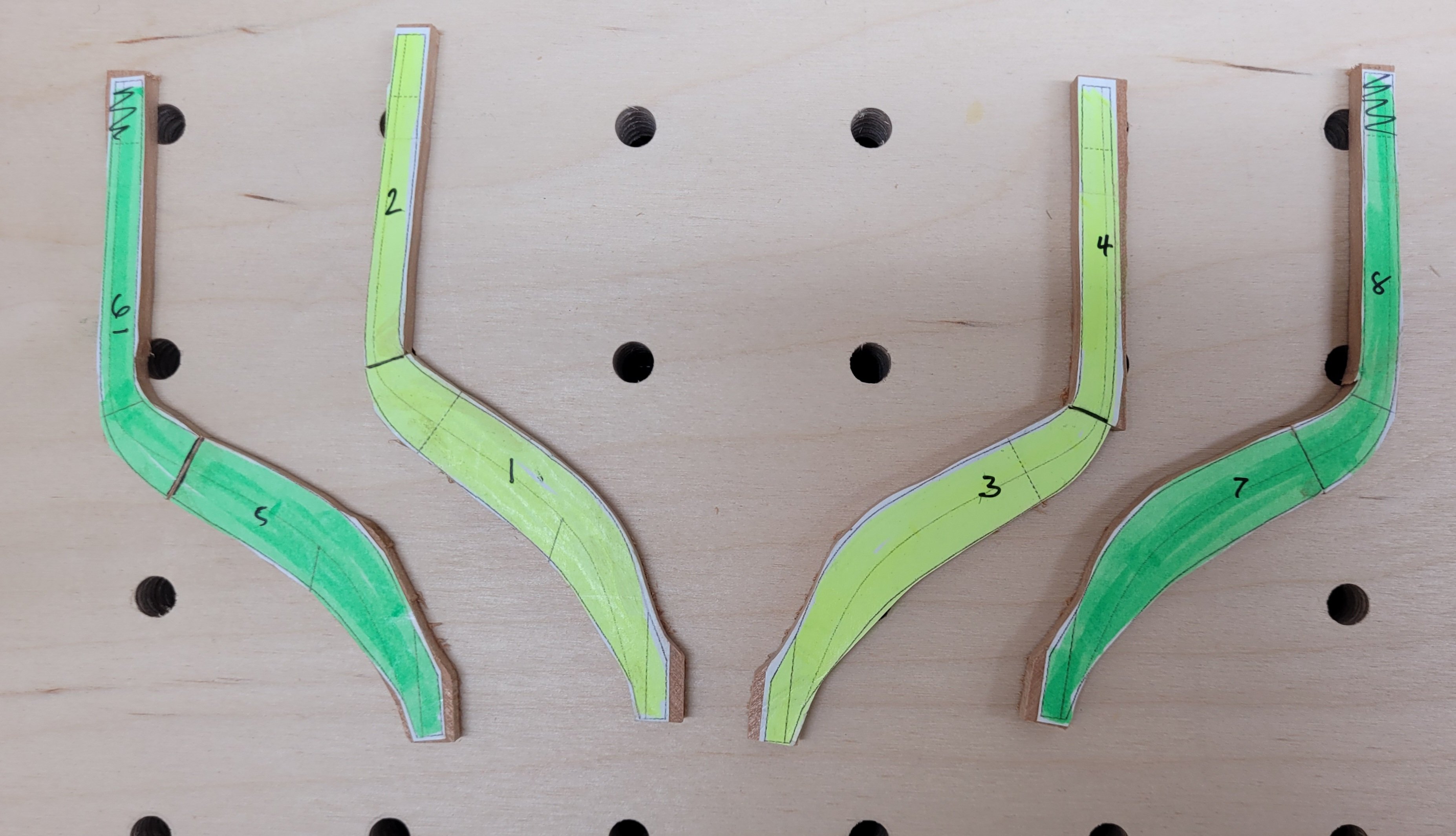
Just a quick update today. I have been continuing work on the aft cant frames, albeit somewhat slowly. I followed the same process as before to make aft cant frames 3 and 4. These were then glued to the keel and small spacer blocks fitted between them and aft cant frame 3 to keep everything secure and supported. I'm endeavouring to keep everything as equal and consistent and symmetrical as possible so hopefully that is working. I have also cut out the pieces required for the remaining three aft cant frames - 5, 6 and 7. Once these have been made and installed I plan to do some limited fairing whilst access to the inside of the frames is still fairly easy.
- 92 replies
-
- 12
-
-
Hello, I have been progressing with my work with the aft cant frames. Following the helpful advice received above I marked out the bevel line on the rear of frame AC 1 and took off some of the excess wood prior to installing the frame. I was careful to keep well away from the line so that there was still enough wood left there to allow for a proper fairing of the frame further down the track. Before I could install frame AC 1 to the keel I firstly needed to cut a notch into it so that it could fit correctly to the wing transom. A small section of the rear portion of the frame was removed with chisels so that it would fit around the wing transom at the correct angle. I then sanded the foot of the frame to the 17.5 degrees using my disc sander and its adjustable table. I was then able to glue the frame sections to the keel using a variety of squares and clamps to ensure it was vertical and was in the correct position. Frame AC 2 was a much simpler affair and was also glued to the keel after the foot had been sanded to 14 degrees. I used some offcuts of wood to make small wedges to fit at the top of frame to hold them more securely in place at this stage but these will be removed later in the build. The frames have also been left too tall for the present and will be reduced to their correct heights once they are all in place.


- 92 replies
-
- 11
-
-
Thanks for the advice. I'll carefully take some of the excess off the rear of frame AC 1 before attaching it to the keel.
-
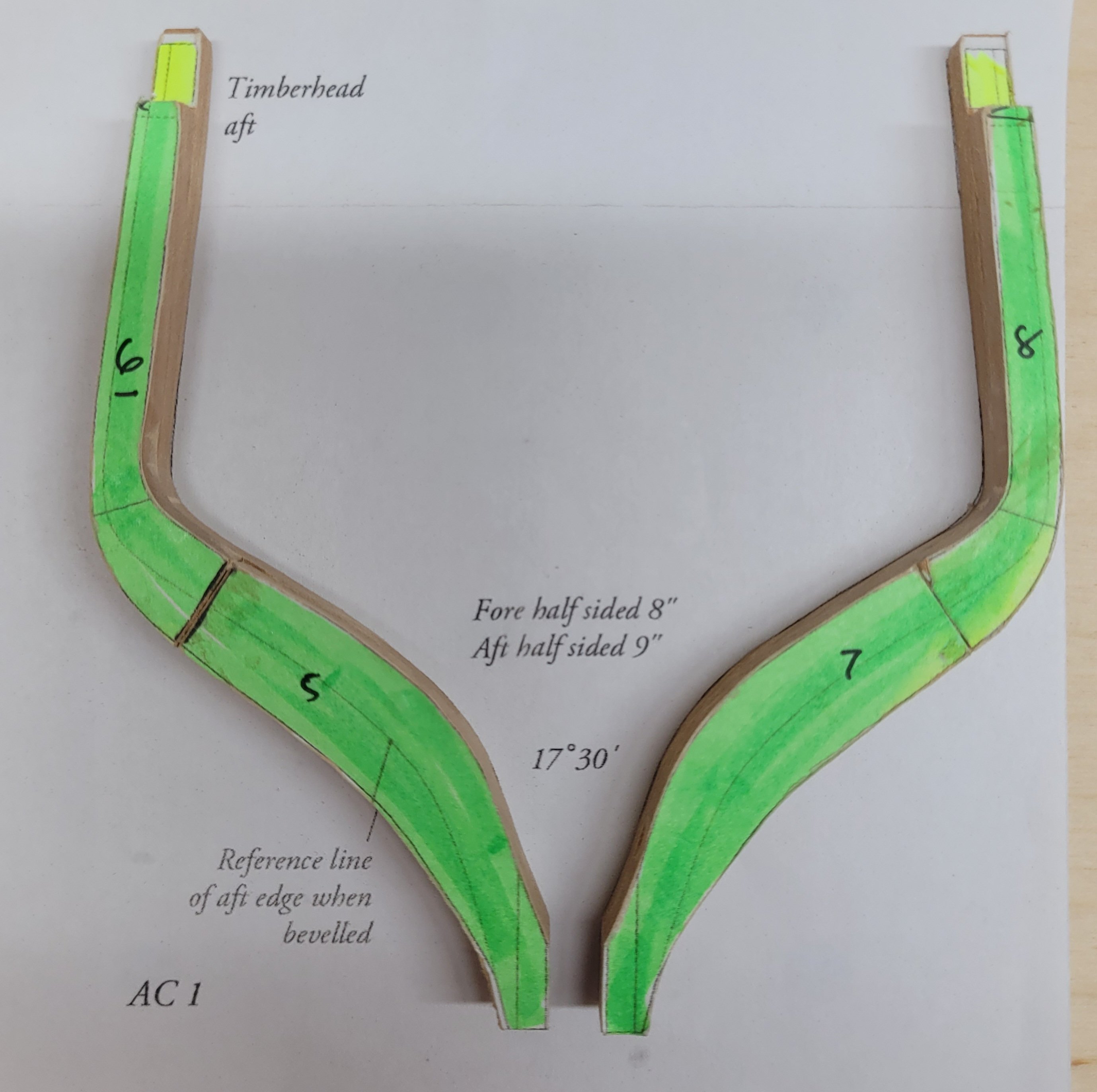
Merry Christmas everyone!! I hope you all had a great holiday. I was excited to start on the next step of the build - working on the frames. David's book suggests working on the aft cant frames first of all and so this is what I have done. All of the frames for the Hayling Hoy are doubled frames with simple butt joints between the futtocks and top timbers. There are seven aft cant frames in total and they are made from either 8" or 9" stock. As this is my first foray into frame making I decided to start off by simply using up two small pieces of spare stock which was thicknessed to 8" and 9" and these were just large enough to allow me to glue on the templates for the eight pieces needed for aft cant frame 1 (AC 1) and the eight pieces for aft cant frame 2 (AC 2). The aft side of AC 1 is made up from 9" stock whilst the fore side of that frame is 8". Both sides for AC 2 are 8". The templates were cut out from the stock just a little oversize with the scroll saw. I glued together the parts for AC 1 on a flat board on which the paper pattern was placed. I was then able to use the spindle sander to finesse the shape of the frames to just a fraction oversized. Due to the shape of the hull the rear part of AC 1 will need to be faired to quite an extent and the final shape of the aft edge of the frame is helpful provided on the pattern. At this time though I haven't made any attempt to pre fair that edge - I'm not sure if this is something that will be easier to do once the frame is in place on the keel or not? Do you think I should make a start on that before affixing the frame perhaps? Obviously each cant frame sits at a slightly different angle to the keel and the foot of AC 1 needs to be cut at 17.5 degrees. I think it will be easiest to set this angle on the table sander and shape the foot that way. I think I will make frame AC 2 and then get both of these frames fixed to the keel before I make the parts needed for the remaining cant frames. Any advice you have on framing would be most welcome!


- 92 replies
-
- 10
-