Martes
-
Posts
981 -
Joined
Content Type
Profiles
Forums
Gallery
Events
Everything posted by Martes
-
3D Brig 'Rose' in Blender 3.3x
Martes replied to 3DShipWright's topic in CAD and 3D Modelling/Drafting Plans with Software
Interesting, indeed. On naval ships the sand was used in battle or during firing exercises, but it was brought from the hold in buckets. -
3D Brig 'Rose' in Blender 3.3x
Martes replied to 3DShipWright's topic in CAD and 3D Modelling/Drafting Plans with Software
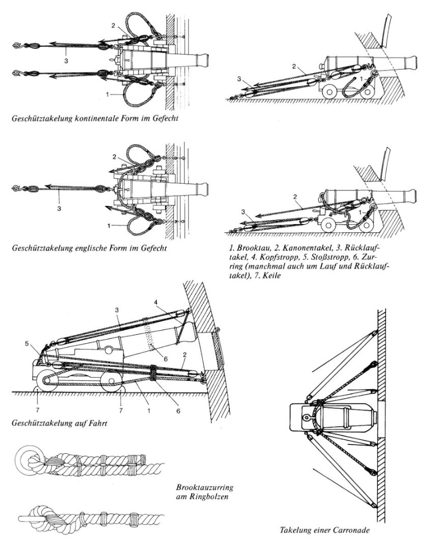
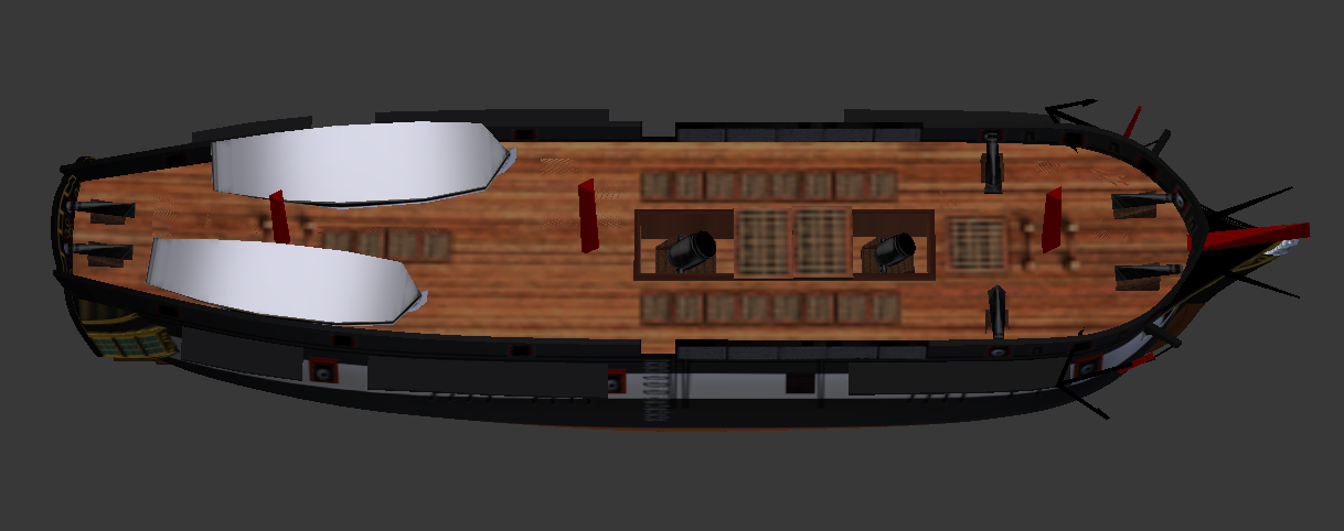
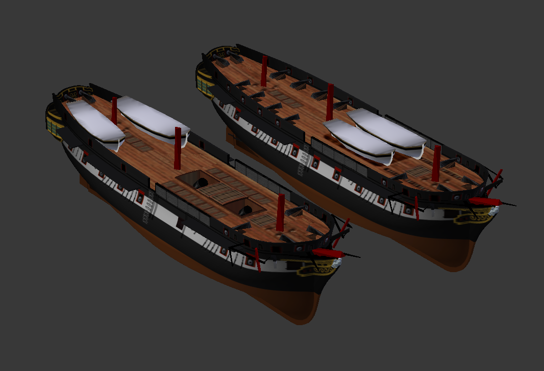
As to changes in rigging - yes, that's the simplest solution. 1. The barrels look completely out of place there, and being not secured are certainly a hazard. Nobody in their right mind would keep powder kegs(!) above the waterline and outside powder room. It's downright recipe for explosion. Do get rid of them 2. Washed, let's say. 3. What do you think the wheel turns on a sailing ship? On a frigate the wheel turns a tiller that is under the deck (under the ceiling of the wardroom), and you simply don't see it, but the rudder can't turn without the tiller. The brig doesn't have that luxury of the space, so it works like this: 4. I am not sure I follow your train of thought regarding the deckhouses and their connection to quarter galleries, but they are present on most of the known plans. Here is a model with the inside of one, and they, as you can see above, do not impede the tiller. And they are a very handy feature to have on deck, very. 5. Same about the flying forecastles. They were introduced in 1780's at least, and feature even on earlier standard brig models, even before the mass introduction of carronades: 6. That is perfectly understandable 7. Going full Jacobite, are we?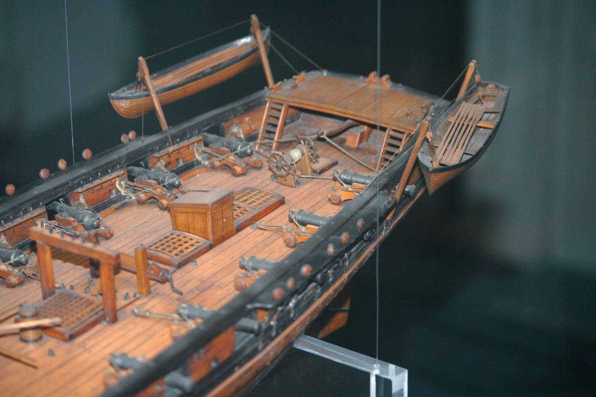
Brig18guns-2.jpg.bee7d1f8f335ae920f34ad35ade408af.jpg)
-
3D Brig 'Rose' in Blender 3.3x
Martes replied to 3DShipWright's topic in CAD and 3D Modelling/Drafting Plans with Software
Some additional observations. 1. What are those barrels for near the capstan? 2. The hammocks are folded to cylindrical, not rectangular packages. 3. The tiller should be visible behind the wheel, as there is no place to fit it below the deck: https://www.rmg.co.uk/collections/objects/rmgc-object-84378 https://www.rmg.co.uk/collections/objects/rmgc-object-84401 4. Those little deckhouses aft (one of which is, if I recall correctly, a quarter-gallery, and another either chart room or flag locker) are absent. 5. Flying forecastle (the deck cover forward) is also missing. 6. For the level of detail you aim for, the carronades miss a lot of tackle - and yes, I know it's a rabbit hole, deciding what to show and what to omit and why. 7. The flag - it should be either white, red or blue ensign, not the union jack. British ships never used the union jack as a national flag.
-
3D Brig 'Rose' in Blender 3.3x
Martes replied to 3DShipWright's topic in CAD and 3D Modelling/Drafting Plans with Software
Very quick and visual-only comparison with the Sophie sail plan gives this: The bowsprit is definitely too long for the masts, and the spanker is too small, even if you leave the masts intact, and it leaves an acute sense of disproportion of the rig. Niagara is closer to Baltimore schooners and makes an incorrect prototype for rigging, her hull is far too different from Cruizer-class brigs and has different requirements. Also, it is possible that your ship is riding slightly too high, as if underloaded.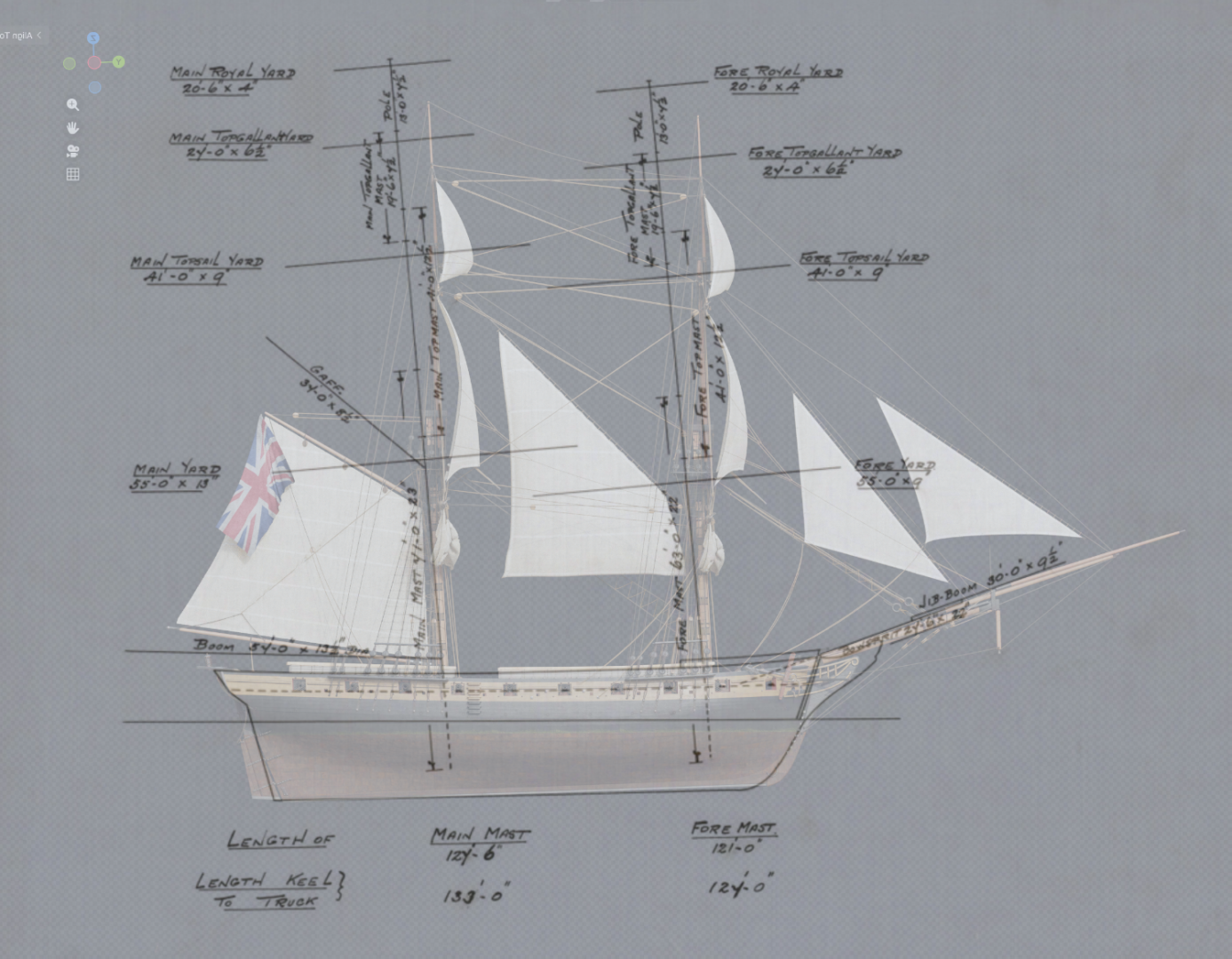
-
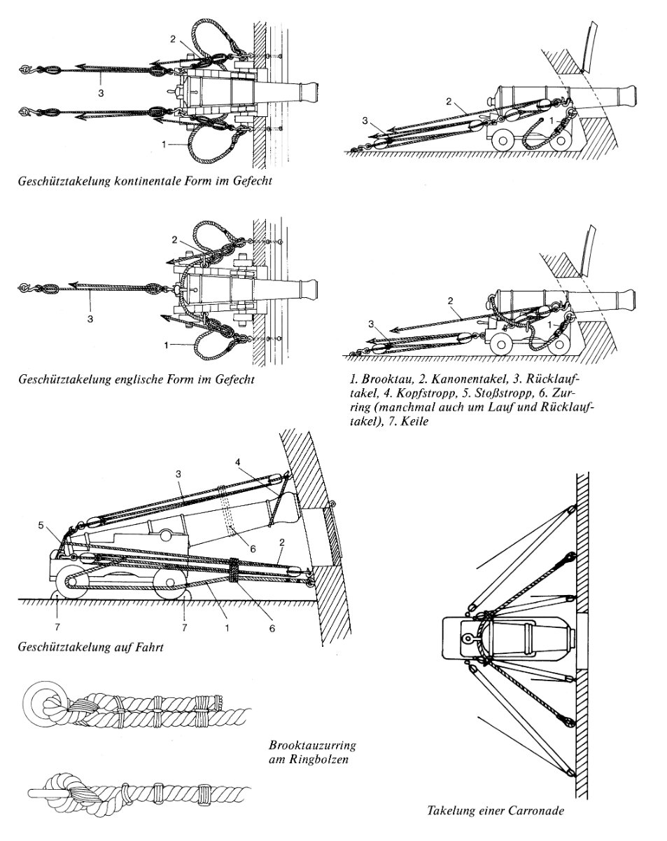
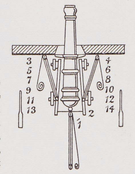
The game I am tweaking has a basic rule of a thumb considering lower deck ports closed at sea state that is equal to gunport height in feet. I.e. a ship with lower deck 6 feet above water would be able to keep them open in sea states 1 to 5. Roughly it corresponds to how it was done. But there is a principal difference between the habitability requirements of the lower deck of a two-decker (which was doubling as berthing deck for the crew) and the gun deck of a frigate, that was for at least half of it's length occupied only with guns, and the crew housed on the lower deck, and officer's cabins being separated by wooden bulkheads. Note that many of the upper deck (or main deck on frigates) ports did not have lids at all, it was considered that the open ports enable to drain the water entering from above at the waist. Lids began only where officer's cabins were located.
-
Would probably mean all gun ports open for ventilation and guns run out. At least most of the paintings I've seen represent the ships in this state in such weather. Should it be somewhat rougher, the lower deck ports will be closed with guns fixed within in some way or other (depends on alert state), but upper deck and fc/qd guns would most probably be still run out.
-
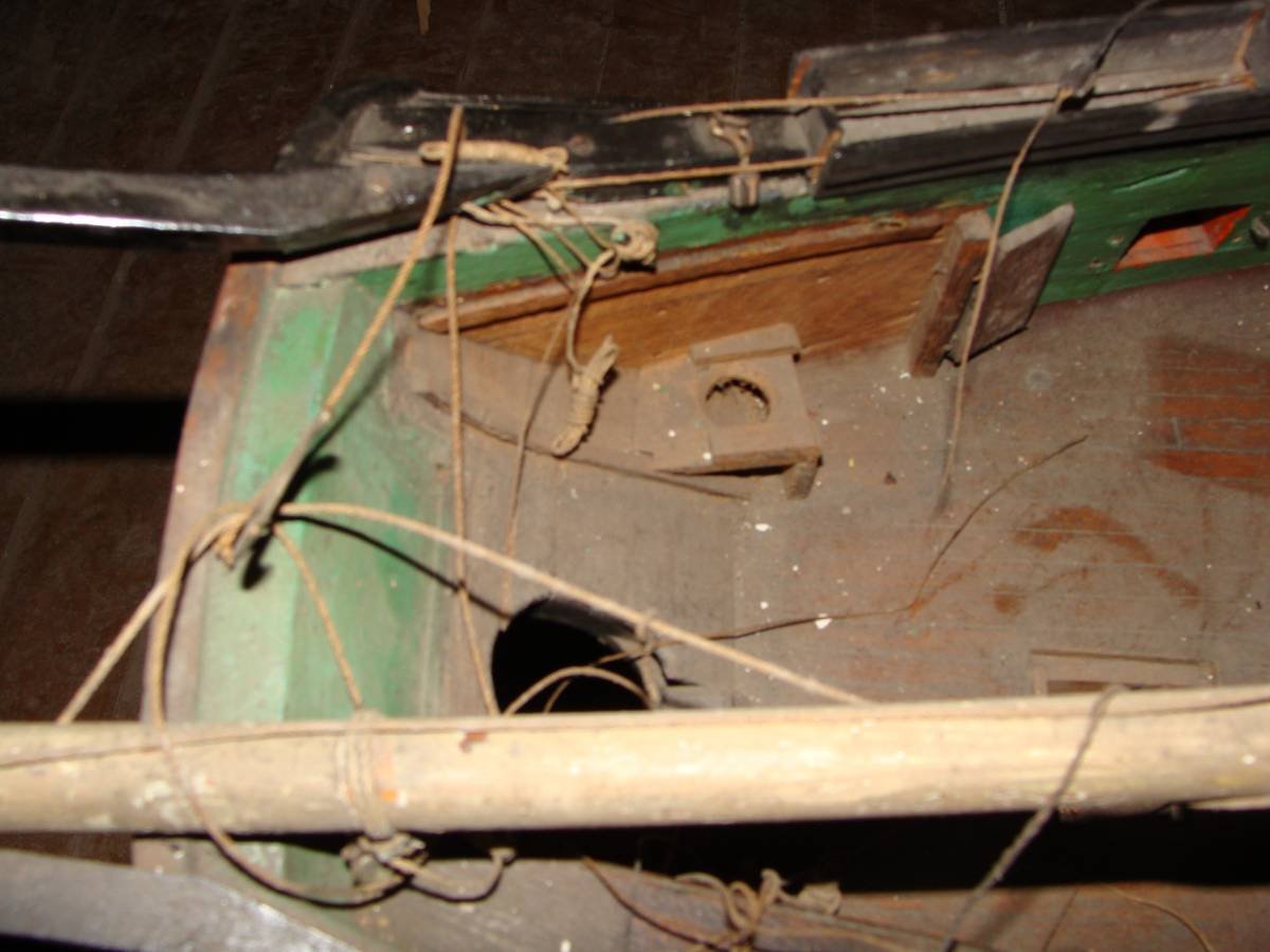
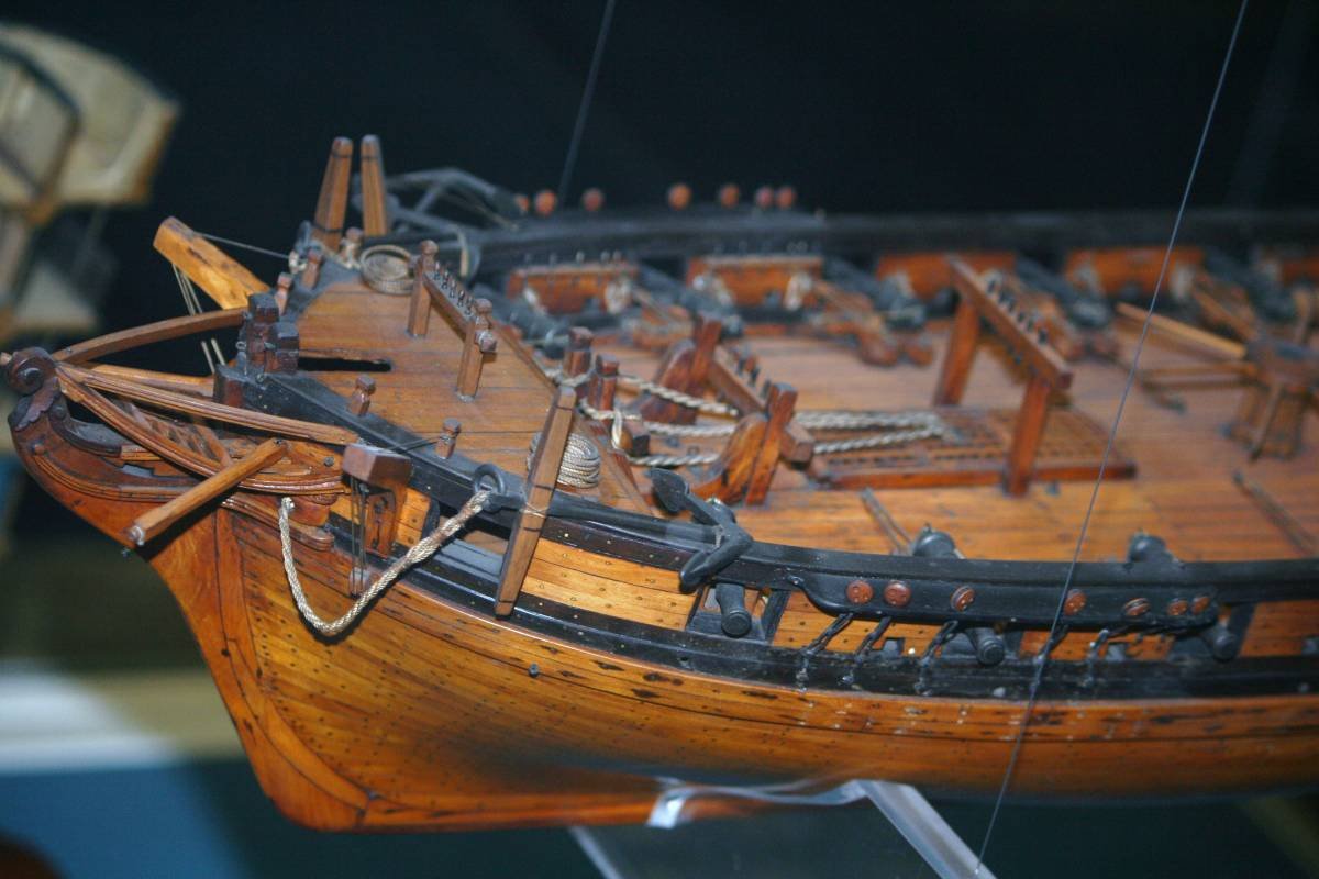
There was another, even more extreme option - when the gun was stored parallel to the hull, lashed sideways. It allowed more space (and thus was used on indiamen), or in very heavy weather, but it effectively disabled the gun for the foreseeable future, since you would need very favourable conditions to bring it back to firing position.
-
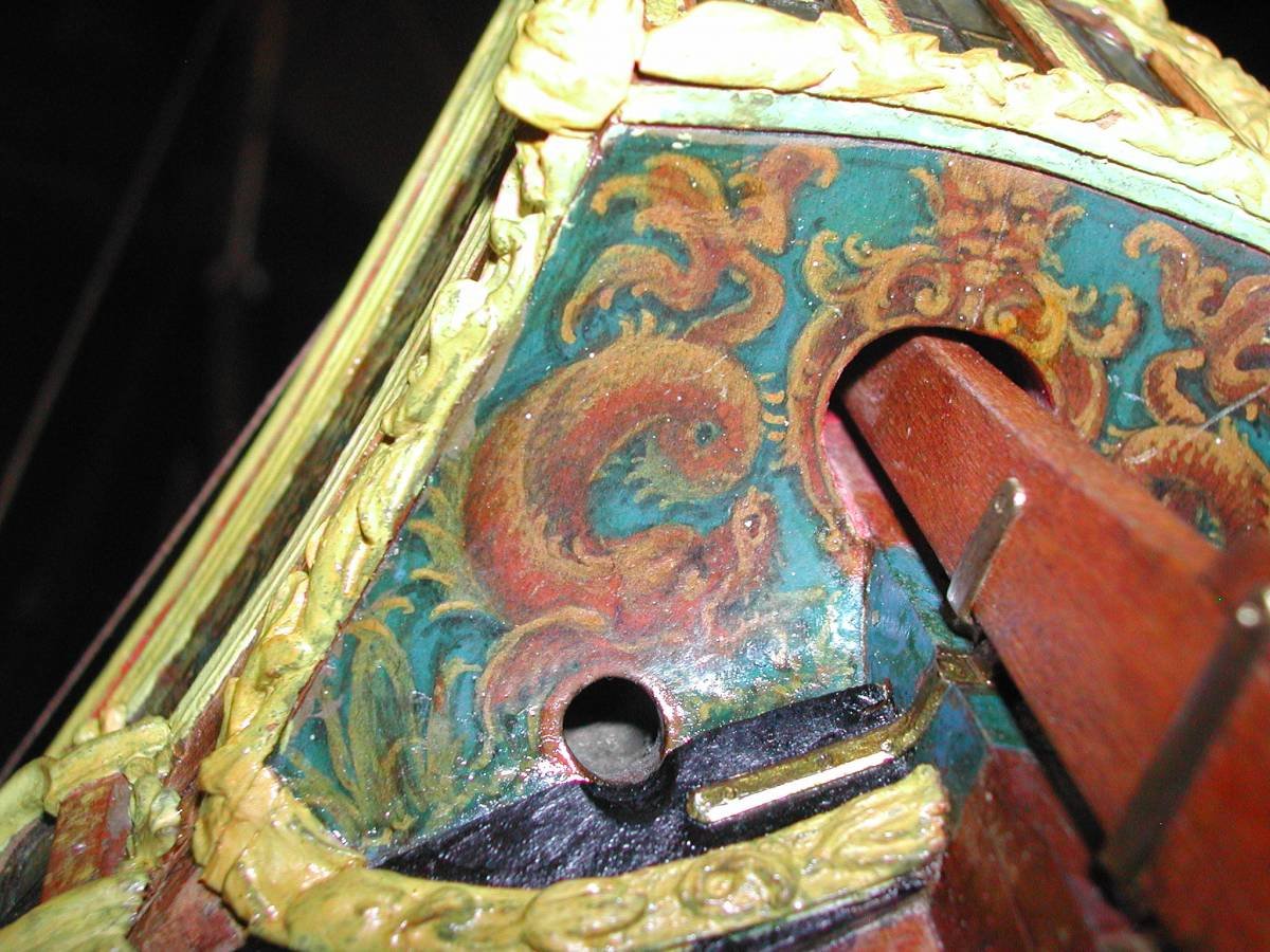
I guess this is the closest to what you were looking for
-
Obviously, plus the tackles.
-
If I recall correctly, stowing the guns lashed to the sides was almost exclusively done when expecting very heavy storm, or on indiamen, because it is a difficult, dangerous and long process of getting them back to position if needed. Later carronades and even heavier guns had pivoting mounts, but that's more into the 19th century.
-
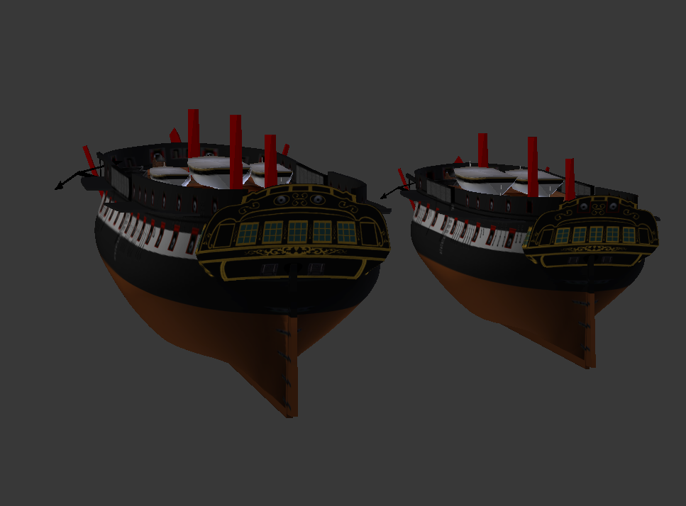
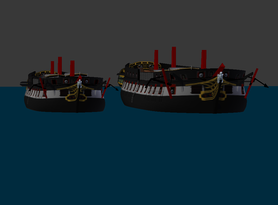
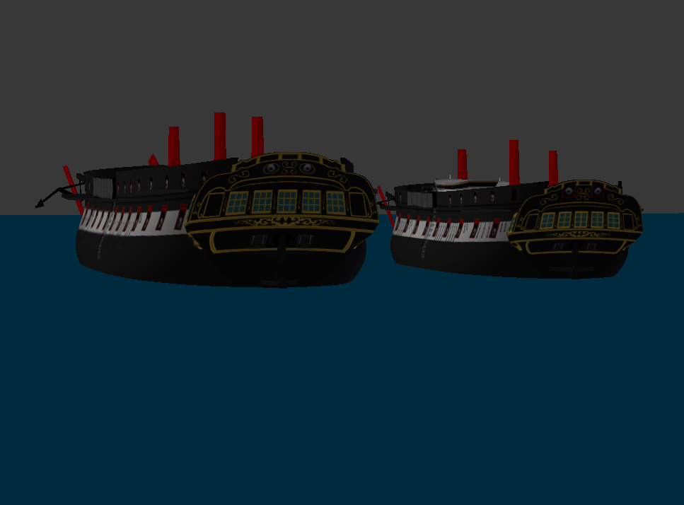
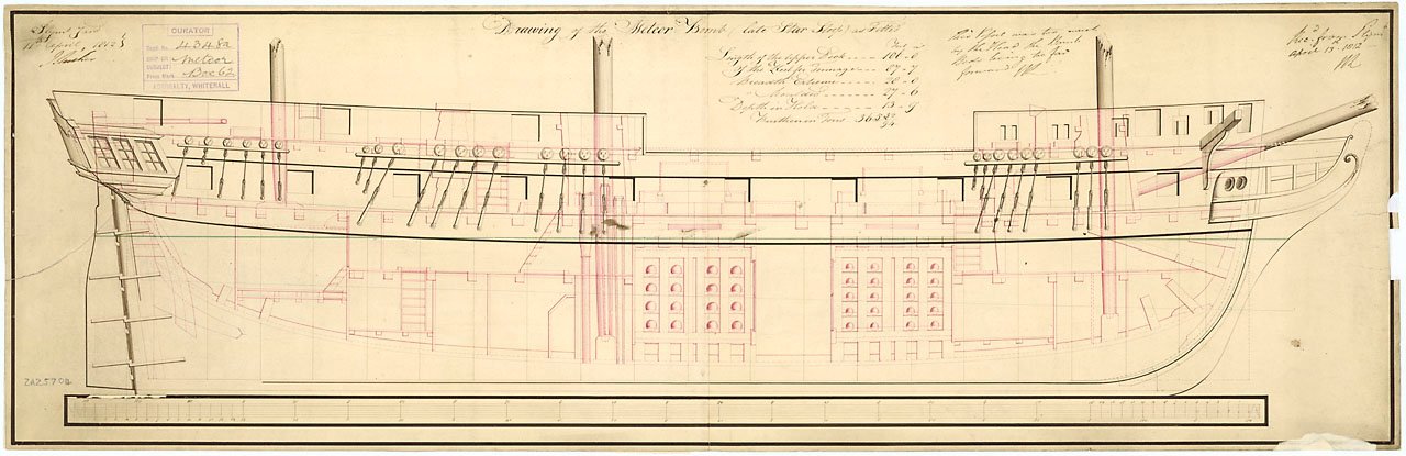
One of the units that was very needed, but eluded me for some time was a sloop. Small ships should be relatively frequent, but somehow I haven't got around to making one for a long time. I looked at the Bonne Citoyenne and Fylla, then I thought I needed something that can (at least potentially) be made in both open and quarterdecked variant and turned my attention to Cyrene, but still somehow held off. Then I found a plan of a Russian corvette, the Spitzbergen of 1803: And the more I looked at the plan, the more something rang very familiar in the shape of this hull. The lines looked like something I definitely saw already. Endymion. No surprise here, the Speshny class was already in series, and highly regarded. But it definitely gave me an idea. And since scaling the design up and down was something not unknown of, I thought I might just do the same. So I took Endymion's hull, scaled it down, slightly squeezed from the sides, replaced the deck, fitted a different stern and adapted head, applied a new texture... and got a ready quarterdeck corvette. The differences between the resulting ship and the original draught of the Spitzbergen (straight rudder-post, inclined keel and slightly different shape of entry) are negligible enough and certainly a small price to pay for getting a new ship with so little effort And so, I got a neat little 110ft corvette, of sufficiently French lines and Regency finish to be able to represent a ship of this class in almost any European navy, fit for escort duty, surveying, gunboat diplomacy and exploration voyages. What else would I want? A bomb vessel, of course! Well, I did have some sort of it, restoring a shabby model of a transport from game files and utilizing an unused gun caliber to make some sort of bomb vessel capability, but looking at conversion plans for Meteor (ex-sloop Star, a ship of very similar size): I thought it perfectly possible to follow the scheme, and make a bomb vessel of my own:

-
3D Brig 'Rose' in Blender 3.3x
Martes replied to 3DShipWright's topic in CAD and 3D Modelling/Drafting Plans with Software
It's either camera angle, or she looks somewhat undermasted. Niagara, being very different from British architecture, is hardly a suitable prototype. Check against this, : https://commons.wikimedia.org/wiki/File:Sophie_(1809)_RMG_J0135.png and this: https://www.rmg.co.uk/collections/objects/rmgc-object-66685_RMG_J0135.png.82c907d8dacc4a32c1feed44e998fc1d.png)
-
William Sutherland's concept of ship hull design, 1711
Martes replied to Waldemar's topic in Nautical/Naval History
On a slightly ironic side note it does look like it happened exactly overnight on January 1st, 1700. Or maybe 1697. Based on surviving plans anyway. -
William Sutherland's concept of ship hull design, 1711
Martes replied to Waldemar's topic in Nautical/Naval History
Yes, it looks very interesting, and I think comparing the model to the plan can give the answer to the sternpost question. I shall check it sometimes -
William Sutherland's concept of ship hull design, 1711
Martes replied to Waldemar's topic in Nautical/Naval History
It's not just that plan, see for example this: Or even the stern of the Sovereign of the Seas from Boston Museum: and my attempt to solve it: https://modelshipworld.com/topic/23981-early-17-th-century-pseudo-perspective/?do=findComment&comment=708359 https://modelshipworld.com/topic/23981-early-17-th-century-pseudo-perspective/?do=findComment&comment=708755 (Sorry for linking posts, it would be a little difficult to recreate the formatting again)

-
William Sutherland's concept of ship hull design, 1711
Martes replied to Waldemar's topic in Nautical/Naval History
About that early 17th century English drawing standard, maybe you know how to interpret it. While the plan appears to be a profile with turned bulkheads, the sternpost is somewhat obscured by a part of the hull in pseudo-3d fashion: Should one assume that to recreate the real profile the sternpost and rudder should be moved slightly back?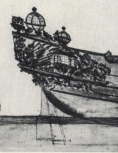
-
William Sutherland's concept of ship hull design, 1711
Martes replied to Waldemar's topic in Nautical/Naval History
Well, Lord Danby certainly didn't lack neither imagination nor resources, since he apparently was able to build the ship. -
William Sutherland's concept of ship hull design, 1711
Martes replied to Waldemar's topic in Nautical/Naval History
Yes, it's very revealing about the practices of the time. 17th century was very different from 18th -
William Sutherland's concept of ship hull design, 1711
Martes replied to Waldemar's topic in Nautical/Naval History
I think I have missed this point. Still, it's something very puzzling. -
William Sutherland's concept of ship hull design, 1711
Martes replied to Waldemar's topic in Nautical/Naval History
As far as I remember, the "as taken" plans were taken by measuring a number of points along the frames (with or without planking, depending on the depth of refit the ship was undergoing) and connecting them. I definitely remember somewhere this process was described in detail, and that with planking stripped it should have been more or less reliable form of recording the ship as actually built. It is possible they put some additional reconstruction along the way, but still. By the way, is it possible to tell if La Prompt had square or round-tuck stern from? But what nags me with the Danish ship (by the way, was she built by private or government shipyard?) is that the designer certainly meant something with the inward arc, and it's very difficult to imagine it was negated just like that. -
William Sutherland's concept of ship hull design, 1711
Martes replied to Waldemar's topic in Nautical/Naval History
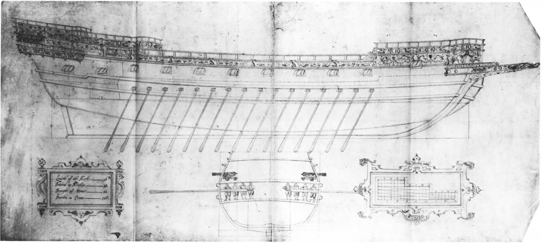
Surely the designer would provide some documentation to the shipyard? There are many relatively complex shapes recorded in "as taken" plans of captured French warships from 18th century in Admiralty archives. See La Prompt, 1702 (earliest recorded prize, I think): https://www.rmg.co.uk/collections/objects/rmgc-object-87615 https://www.rmg.co.uk/collections/objects/rmgc-object-87616 -
William Sutherland's concept of ship hull design, 1711
Martes replied to Waldemar's topic in Nautical/Naval History
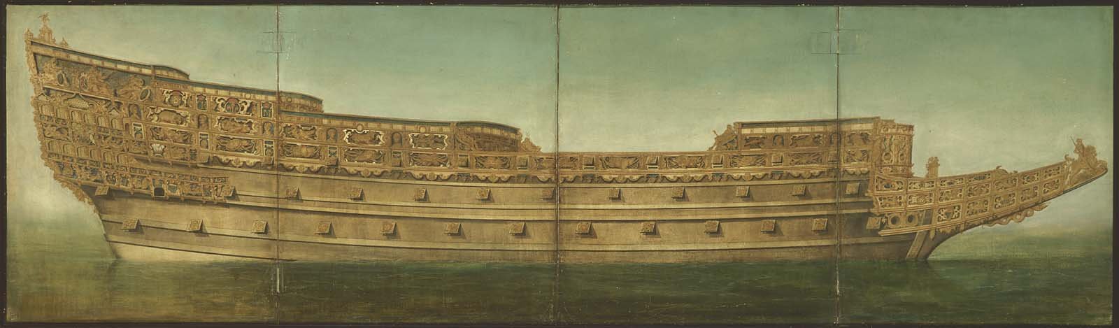
@Waldemar, concerning the Danish design you reconstructed - are you sure that the red curve was not intentional and would not be copied at the shipyard? Why go to such lengths to create a relatively complex shape for all of it to be simplified and shaven off during construction? Could it be possible that the shape as designed was in line with even more extravagant experiments, like the later Lord Danby's Maggot: https://www.rmg.co.uk/collections/objects/rmgc-object-385580 (oh, how I'd love to see the planking plan for that one!) and had some hydrodynamic meaning? -
William Sutherland's concept of ship hull design, 1711
Martes replied to Waldemar's topic in Nautical/Naval History
I once posted them here: https://modelshipworld.com/topic/24626-plans-found-in-hermitage-collection-st-petersburg/ and there was a comment that it's early 17 century English style, but I did not know about Balfour at the time. Also, did you see these plans: https://www.rct.uk/collection/1047387/the-ship-london-on-her-first-voiadge -
William Sutherland's concept of ship hull design, 1711
Martes replied to Waldemar's topic in Nautical/Naval History
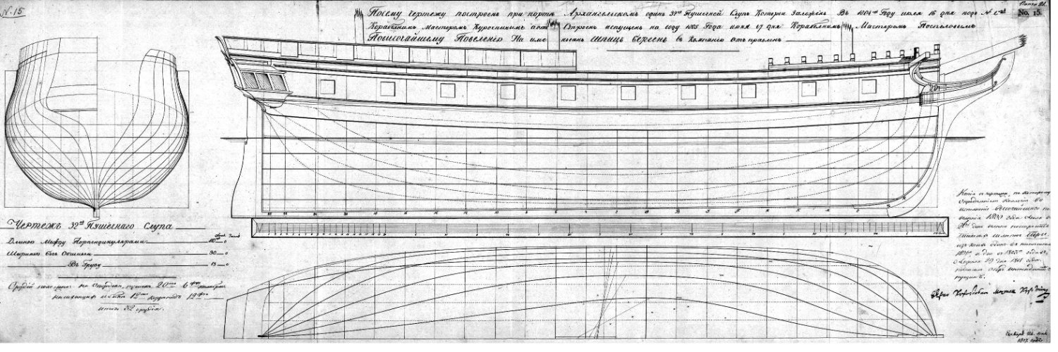
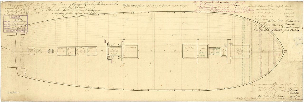
It's a part of a very obscure set of 3 plans that are now in the collection of the Hermitage museum https://www.hermitagemuseum.org/wps/portal/hermitage/digital-collection/02.+drawings/500128 https://www.hermitagemuseum.org/wps/portal/hermitage/digital-collection/02.+drawings/500129 https://www.hermitagemuseum.org/wps/portal/hermitage/digital-collection/02.+drawings/500130 I am not sure if their origin was ever determined, but they look very similar to Balfour's plans from the Danish archive. May be his work or copies.