HOLIDAY DONATION DRIVE - SUPPORT MSW - DO YOUR PART TO KEEP THIS GREAT FORUM GOING! (Only 72 donations so far out of 49,000 members - Can we at least get 100? C'mon guys!)
×


Martes
-
Posts
981 -
Joined
Content Type
Profiles
Forums
Gallery
Events
Everything posted by Martes
-
Purely graphically, shouldn't there be two ladies, one from each side?
-
USF Confederacy in 3D | Blender
Martes replied to 3DShipWright's topic in CAD and 3D Modelling/Drafting Plans with Software
I am not sure if it would help, but while I was working on the Indy, I had a specific problem rotating the gunport lids and found (hell if I remember how I did that) a way to put a rotated local axis into the object, align it with the edge of the gunport, and then rotate the lid about this axis. For the Indy, by the way, I tried to produce the outer shell using Lattice, of all things, and then make manual corrections, but that proved to be in some way even less convenient than just do it by hand from scratch. But then I don't have to cut the resulting model to individual planks.- 107 replies
-
- 1
-

-
- Frigate
- Confederacy
- (and 1 more)
-
USF Confederacy in 3D | Blender
Martes replied to 3DShipWright's topic in CAD and 3D Modelling/Drafting Plans with Software
So for this method to work you need to fulfill two requirements: that your initial run of the vertices and edges should coincide with the planking plan and distances and to be sure that the Solidify would give a correct offset. However be careful. It may be very well possible that since Blender 2.79 that I use the Solidify operator has been improved with it's results on complex surfaces, but my results with it, when I attempted to reproduce the surface of the frames and then extend it to planking was very unsatisfactory, especially around the bow and I had to revert back to manual editing (see my first post about the latest iteration of the Colossus). I find it very useful to keep a "water" object, to be able to verify the smoothness of the waterlines so that more or less all intersections of the hull with it would not produce sudden angled surfaces. Also, take a look at what happens around your keel. There should be no dent there. This is exactly the position the planking edge should touch the keel.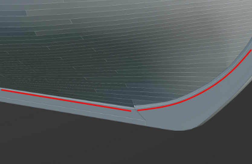
- 107 replies
-
- 1
-
-
- Frigate
- Confederacy
- (and 1 more)
-
USF Confederacy in 3D | Blender
Martes replied to 3DShipWright's topic in CAD and 3D Modelling/Drafting Plans with Software
Is there some automatic process you use to generate the planking, or it is done manually?- 107 replies
-
- 1
-
-
- Frigate
- Confederacy
- (and 1 more)
-
I think it's purely rendering issue. For some reason the program tries to blend the edges of the objects with background color. If it is very bright, some details can go missing, and ropes appear thinner. Probably may be fixed with antialiasing settings, but much easier to give some background like that paper style you posted earlier, or hard black against white. Don't dwell on it.
-
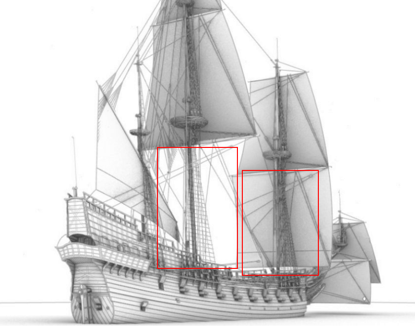
The ropes are thin and likely look something like that from a distance, but in this post: https://modelshipworld.com/topic/31638-„święty-jerzy”-„sankt-georg”-1627-–-reconstructing-an-opponent-of-„vasa”/?do=findComment&comment=975528 they looked more or less all right. I suppose you have to have some kind of world background for the ropes to show normally, since the very last pictures displays the ropes that are shown against the sails and those that are not differently:
-
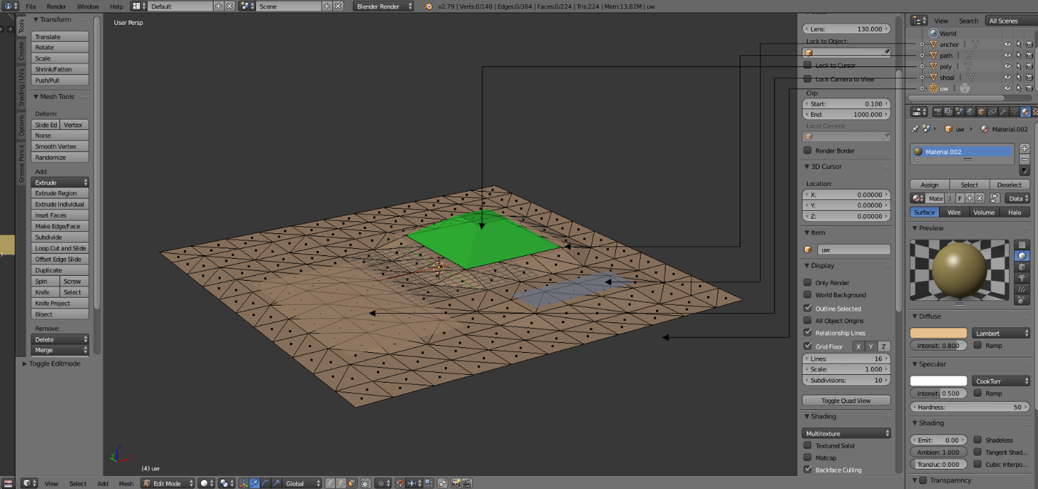
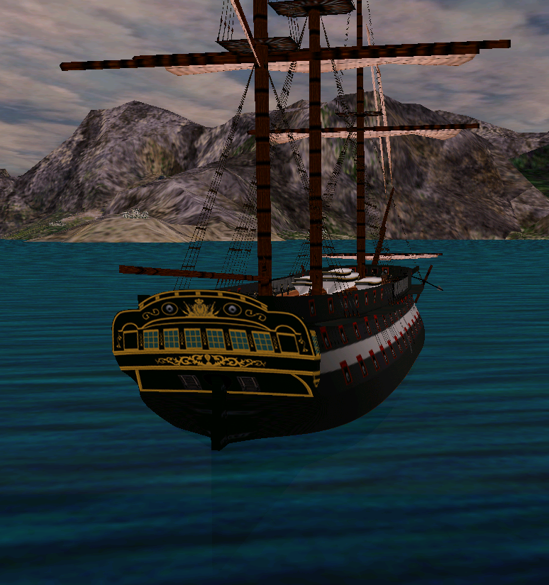
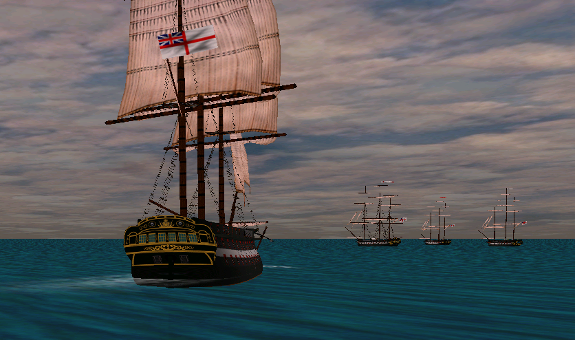
In fact, it depends on three factors. First is the weather. The water is less and less transparent as the wind rises. Second is the presence of a sea bottom mesh and it's color. They do not appear on all maps, but here nice and not very deep sand is present. And third is somewhat connected to camera angle and wind direction. I tried once to make maps for this game, it's technically possible, just very inconvenient, because the terrain mesh should be separated from underwater mesh exactly at z=0, and if a single vertex from the land mesh or a single vertex of sea bottom mesh crosses this line, the scenario crashes on load. It is also somehow possible to place buildings, cities and forts (the game contains appropriate models) on the maps, but I did not go that far. Another relatively practical solution that I have seen on several maps included in the game is that the land mesh is regular, while the underwater mesh is simply a plane with painted features (and corresponding map zones as described below). The "path" object denotes the land collision edge that has to be separately created (and are particularly difficult to generate), "anchor" allows ships to drop anchor, and "shoal" can have limited depth set in scenario editor and thus strand ships that are deeper than this value. The sea, however, is done quite ingeniously, especially for so early engine (1999 or 2000, IIRC) - it is, in fact, a combination of two flat semi-transparent surfaces that have different textures running in different directions, creating a very convincing illusion of moving water. In general, I would love to introduce some accurate geographical scenery into the project, but, again, probably it's better (and easier) could be done in Unity. If only I had the time.

-
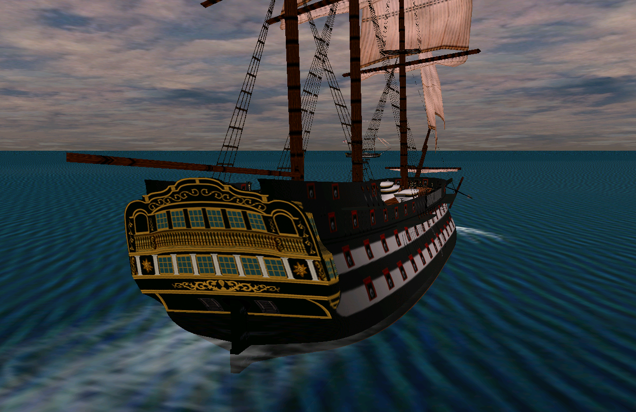
Black and white contour renders are especially beautiful
-
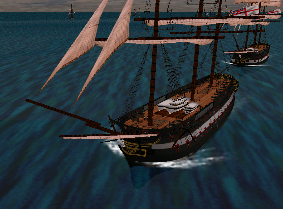
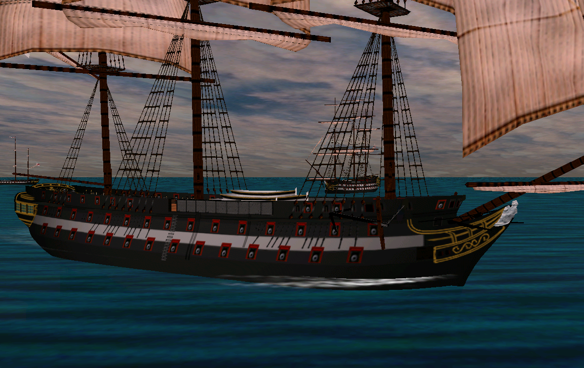
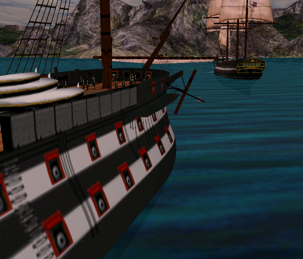
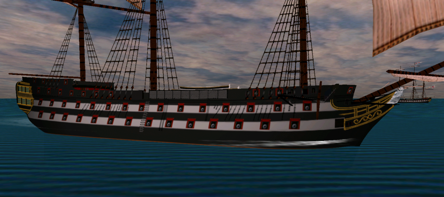
And sometimes, when the conditions permit, you can see the underwater parts of the hulls through the surface.
-
And a dynamic scenery at that. You can recreate various situations, you can even set them to fight and see what happens, it is a tactical simulation, after all. That's why I love it so much. They are alive inside there. If only I could control the camera lens angle here, the screenshots would be even more beautiful, but it would be easier to reimplement the whole game in Unity than find that bloody parameter in compiled C++ code of the original.
-
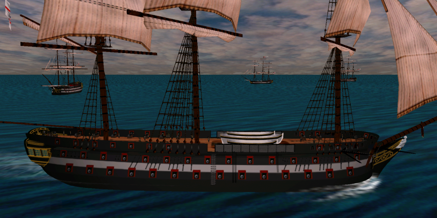
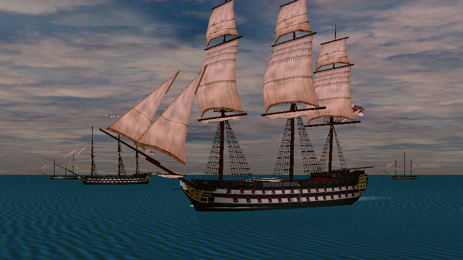
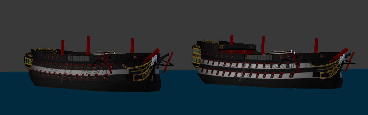
Sailing test for the flush-decked 74:
-
3D Brig 'Rose' in Blender 3.3x
Martes replied to 3DShipWright's topic in CAD and 3D Modelling/Drafting Plans with Software
That would depend on level of readiness, but yes, they did exactly that. Plus one boat on the stern davits across the taffrail. Some links for reference. https://www.rmg.co.uk/collections/objects/rmgc-object-84945 Or two boats could be carried on the quarter davits if prepared for launch: https://www.rmg.co.uk/collections/objects/rmgc-object-84911 And I still think she rides too high in the water. The waterline should be probably around X mark (which is also very anachronistic, as those were introduced somewhere around the beginning of 20th century). But the renders are breathtaking!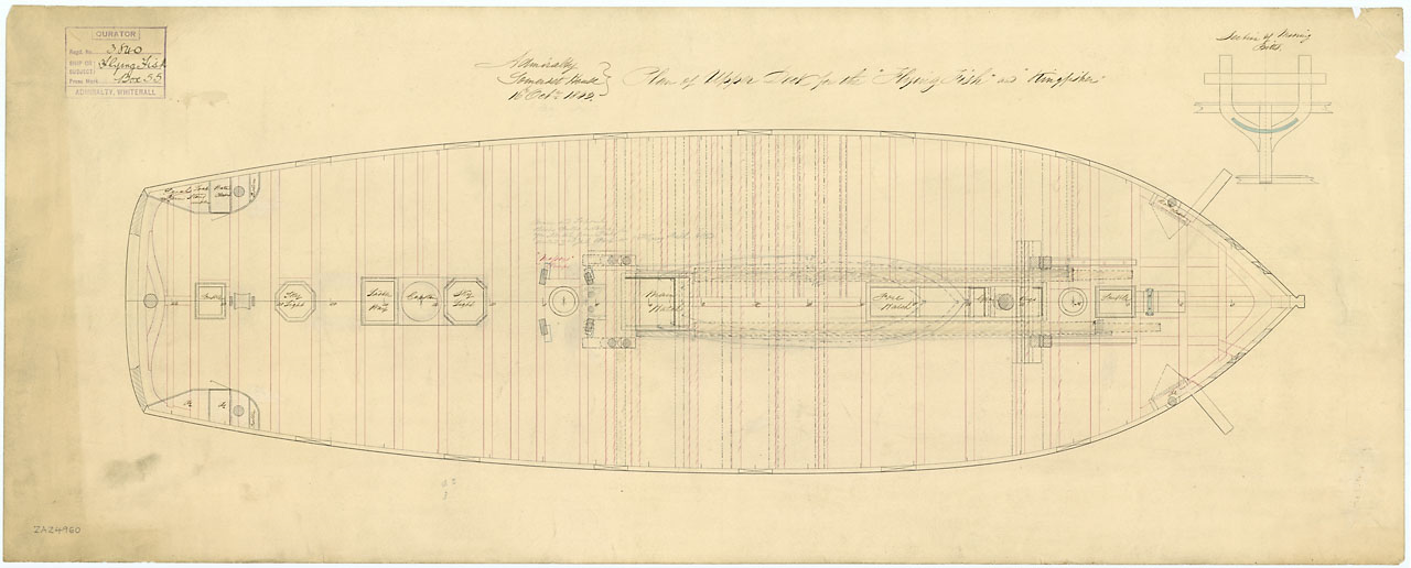
-
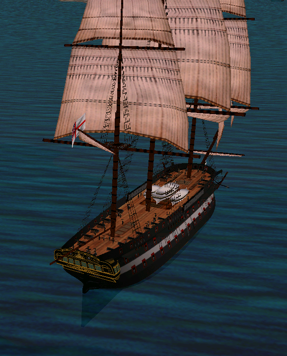
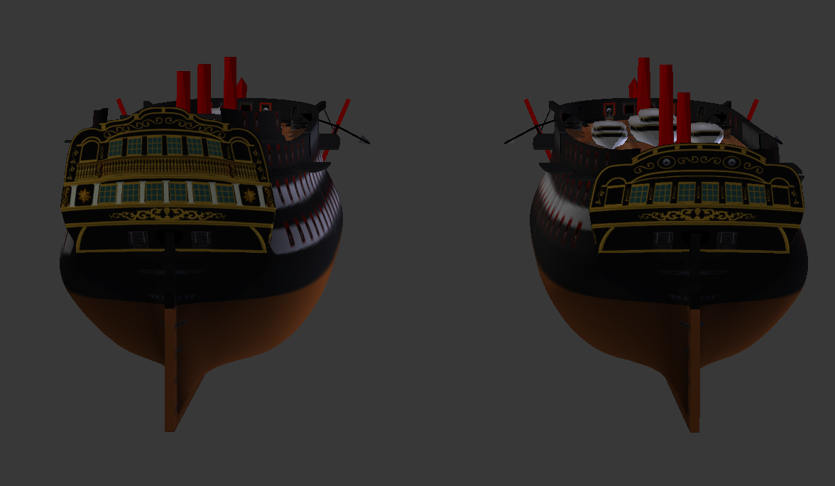
The long spar-decked 74 also differs from the "frigate" by retaining the same head as the ship of the line, while on the "frigate" it is slightly shorter and does not have curved rails. Which one of the two is more powerful - it's a debatable question, but the frigate, having about 150 less crew is certainly more habitable
-
Thanks, I am really glad you like them. Hopefully I will convert the flush-decked version today or tomorrow and show her sailing as well. The Royal Navy had quite a lot of ships based on the Courageux, so making the Colossus as a base was a little bit of a cunning plan on my part (although I was completely unaware of the scale of the copying work that was going on in the Admiralty when I chose which 74-gun ship to make), I just have to maintain a list of precise transformations in case I have to correct something and reimport the change on all the derivative models.
-
A preliminary test of the Blake under sail:
-
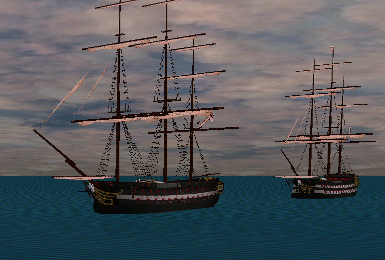
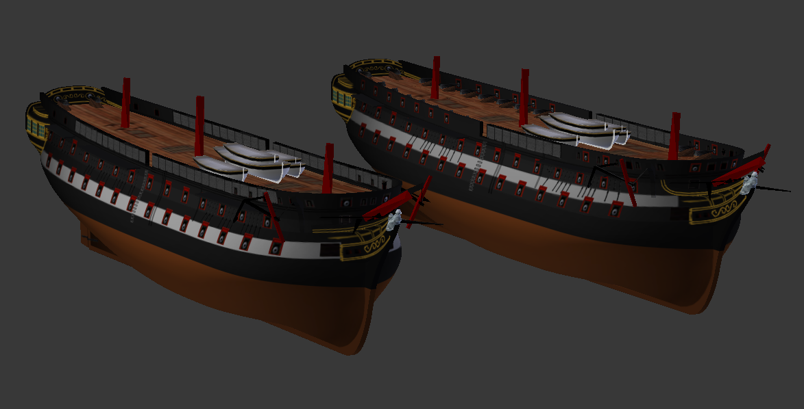
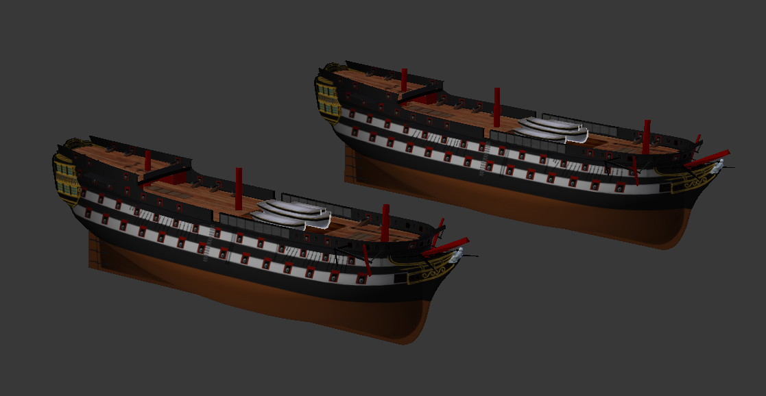
As I already said, the completed hull of the Colossus presents a lot of interesting possibilities. Among other things, the hull can be stretched by inserting a parallel section in the middle, and the Colossus turns into the Blake class: Despite being almost 8 feet longer (180' instead of 172' 3"), it may be a little tricky to spot the difference - note the Blake has more space before and after the battery and an additional upper deck port. This model can represent practically any "long" 74, still smaller than 80-gunners and slimmer than the Temeraire-class ships. Another option, very slightly less historical, is to stretch the hull without the roundhouse, since I have it anyway, but this time the resulting ship would not be considered a frigate, but a full-fledged two-decker with armed spar deck, less only the upper tier of the cabins. The Royal Navy, if I recall correctly, had only one major ship of the line in this configuration, the Plantagenet, which was of a different design but very close in size (plus the St. Lawrence on the Great Lakes, but that's completely different story), so the model will have to do at least for now. The paint scheme is relatively unusual for Royal Navy and is closer to Danish or Russian ships, but it's not to say it was not used at all (at least it appears on a number of engravings) and it suits the design perfectly well.
-
Interesting, that on two versions of the image, the sail is of different size. On the graphical, first image, it's bottom is near where the lower, main staysail should end on the foremast, and it's upper end is closer to the main topmast, and on the painting from artuk it is more or less identical to the maintopmast staysail from the plans. Interesting, how effective it would be - both under the circumstances and in general.
-
It still looks larger on the first picture, but it is close and could have been possibly enlarged. Which corvette is the plan for, by the way?
-
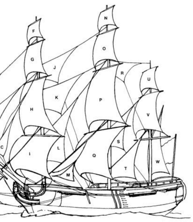
I looked up that much (L below), but isn't it about 1.5 to 2 times larger than the regular depiction of it? Or should it be written off to artist interpretation?
-
USF Confederacy in 3D | Blender
Martes replied to 3DShipWright's topic in CAD and 3D Modelling/Drafting Plans with Software
Beakhead, IIRC. And the wall behind it is the beakhead bulkhead. As each of them is actually a pair (see Intrepid again), you can divide each of them to two and spread them so they cover as much area as possible. Also their thickness is slightly less near the keel and can be slightly wider towards the wale. The French did not use this method, they had straight vertical pairs up to the hawse pieces at the time, so you can rely on the British sources at this place. One thing of note - the Constitution has her straight vertical pairs until the first gunport (as opposed the Intrepid that had them starting from the forward end of the second gunport of the lower deck), and you can, I think, safely follow that example and make at least two of the cant pairs actually straight. The rest of the hull until the last gunport should therefore be evenly distributed with pair-gap, pair-gap. Very small gaps. But yes, it already begins to look much better- 107 replies
-
- 1
-
-
- Frigate
- Confederacy
- (and 1 more)
-
Exactly, it's an enlarged spanker, not an enlarged jib as I thought initially.
-
Problem is this is about the only depiction I saw of such sail for the period, or I seriously missed something.
-
I understand it's not uncommon now, lots of large yachts seem to use something of a kind. But was it uncommon then?
-
It's kind of two times larger than regular main staysails, and is fixed not to the mainmast, but to main topmast.
-
HMS Indefatigable 1794 [Discontinued]
Martes replied to Martes's topic in CAD and 3D Modelling/Drafting Plans with Software
The idea was to create a walkable and potentially interactive environment, getting as close to Hornblower experience as possible (which proved to be quite claustrophobic at places). But that would have required a completely new game development.