HOLIDAY DONATION DRIVE - SUPPORT MSW - DO YOUR PART TO KEEP THIS GREAT FORUM GOING! (Only 20 donations so far - C'mon guys!)
×


Rowboat
-
Posts
142 -
Joined
-
Last visited
Content Type
Profiles
Forums
Gallery
Events
Everything posted by Rowboat
-
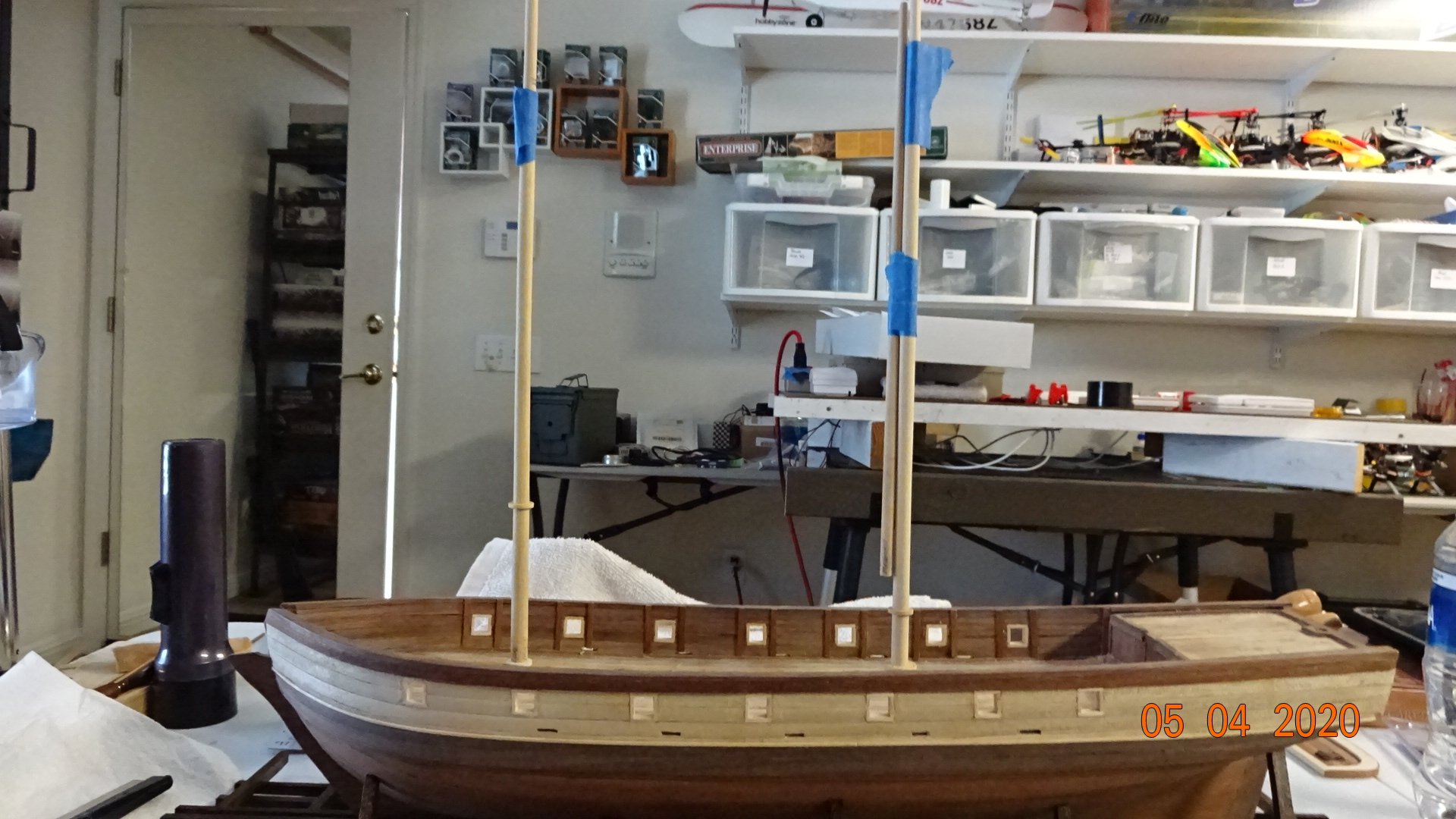
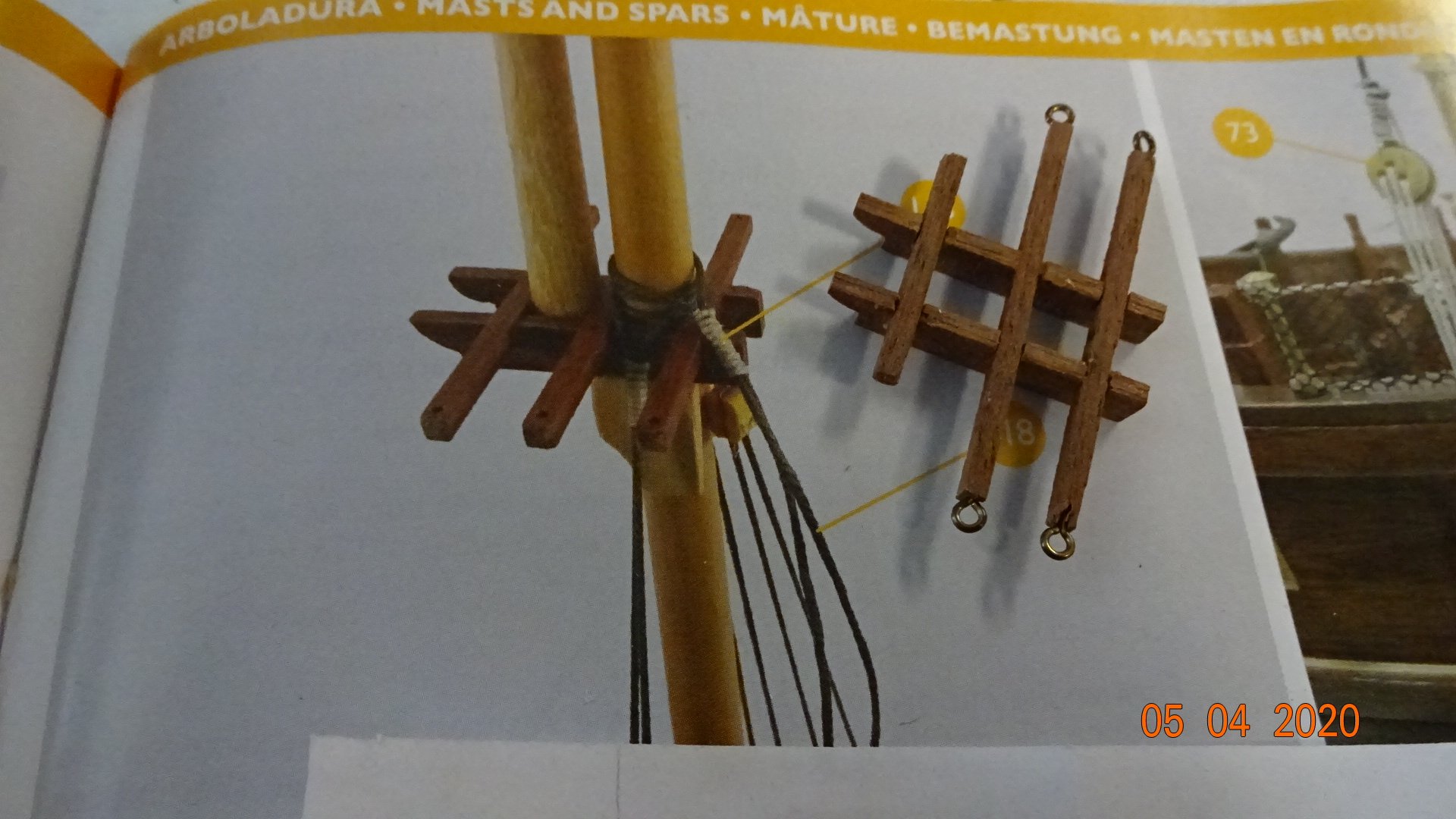
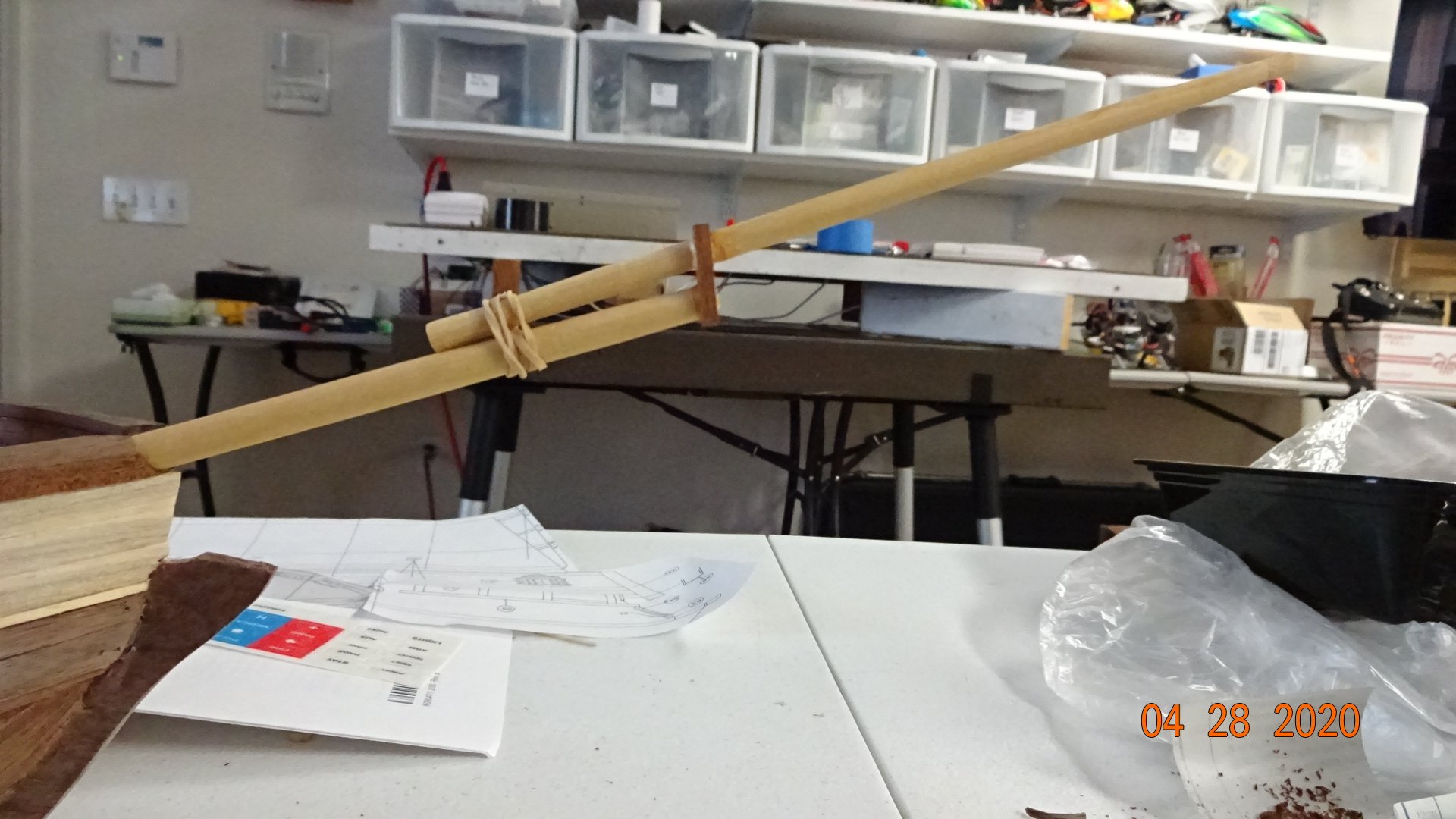
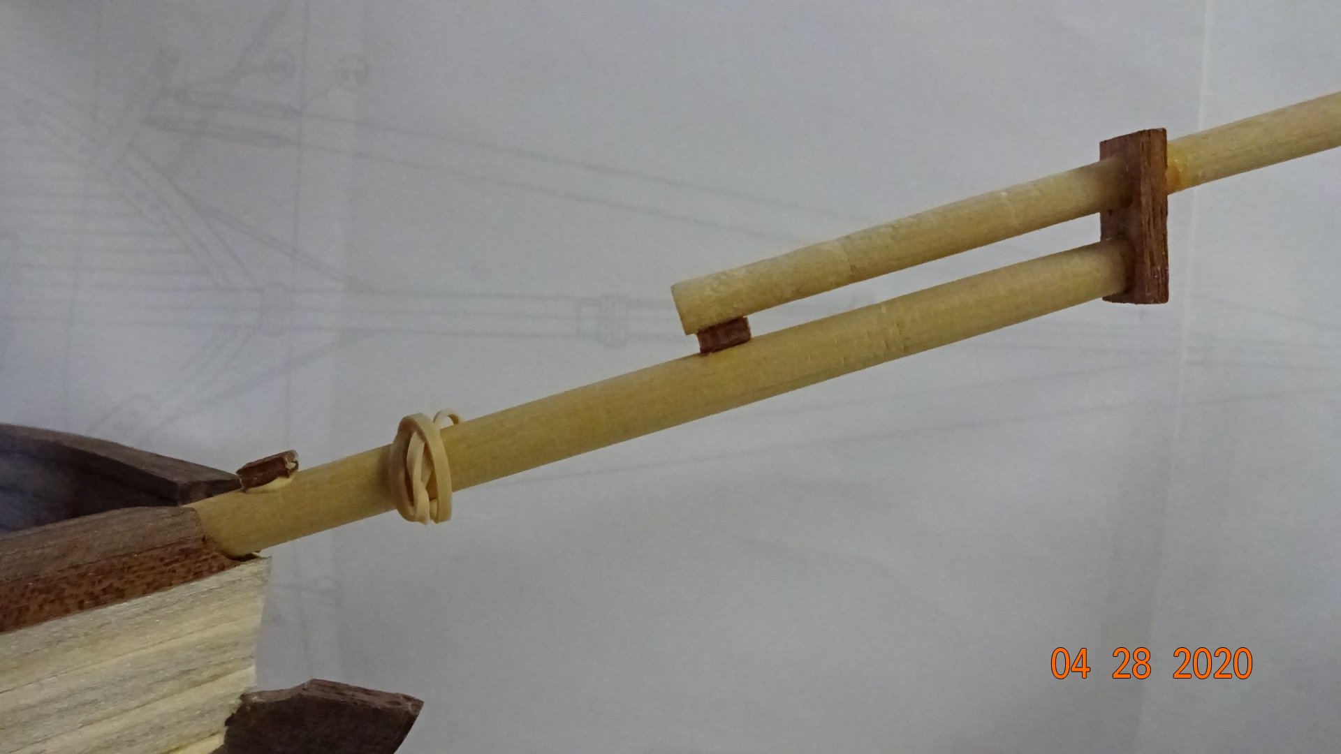
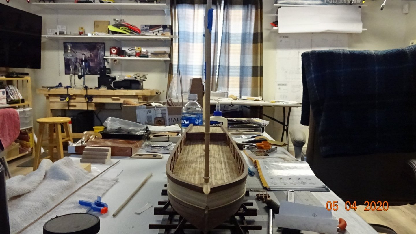
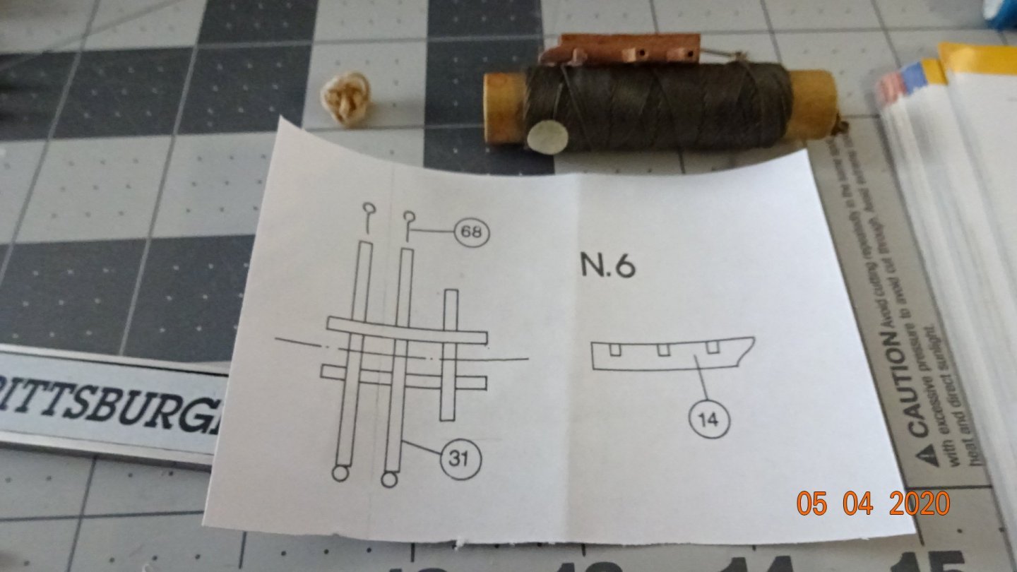
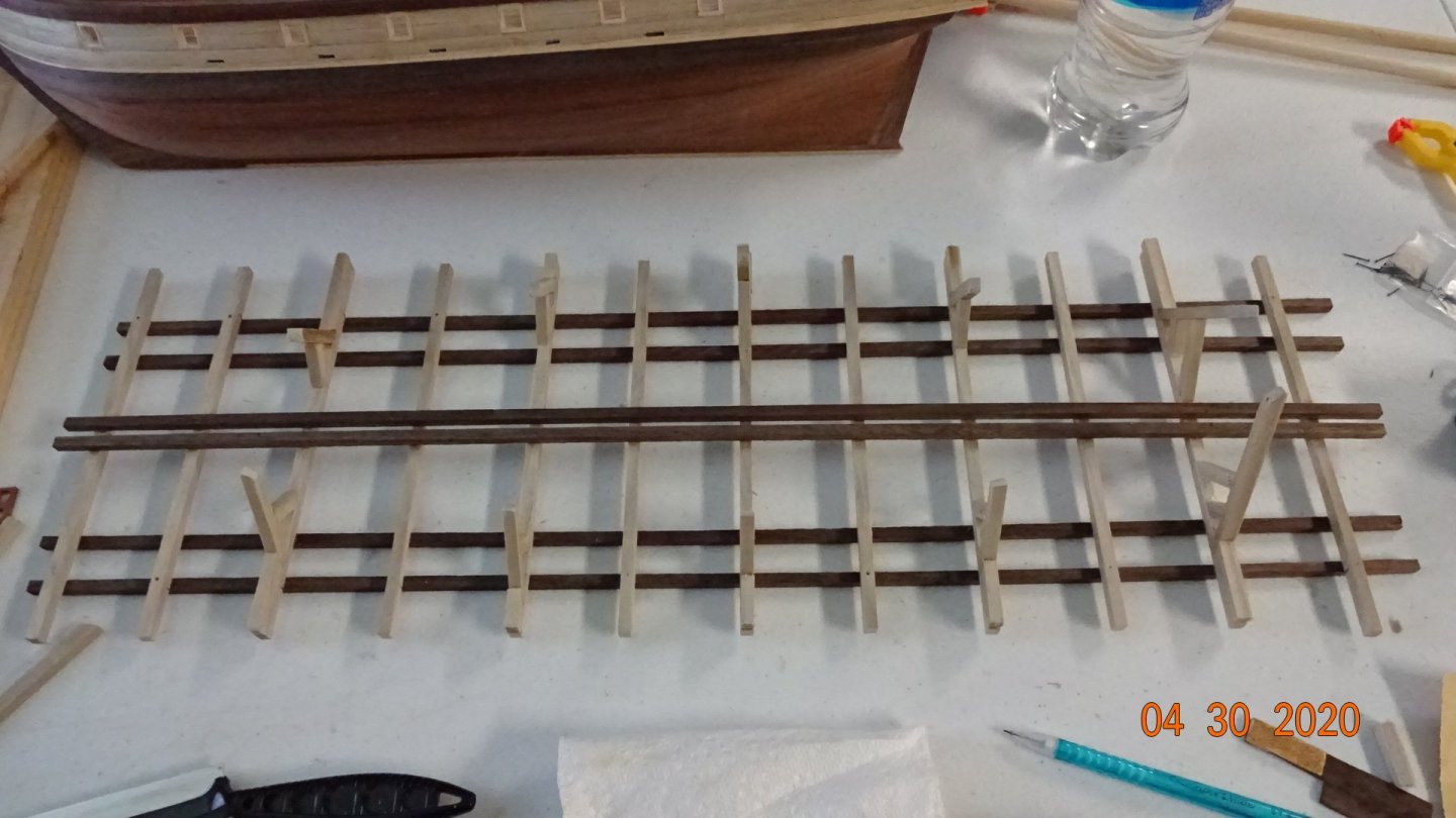
 Didn't mean to cut that last post so abruptly, something came up. To continue .... fitting of the masts. Not to bad, I'll glue them in later when it's appropriate. I did spend some time working on the trestle trees. The plans called for drilling out the ends for some eyebolts. I did split the end of one of the separators but glue resolved the problem. The plan is different than how the manual shows them made. In the manual all three separators are the same length and they have holes drilled through them for rigging lines. If anyone remembers I started this build without the manual ( and lots of missing pieces), I was gifted a manual from a fellow ship builder.👍 Their model must be slightly different than mine, so I need to be wary of just following the manual. Here's a pic showing the issue. Those rigging lines are tied nicely, I need to see if there are instructions on how to do this. I'm accepting any offers on knot tying tips .... 😉 I think next steps are building rails on the poop deck. Will need to mill the wood for that first. Rowboat out.
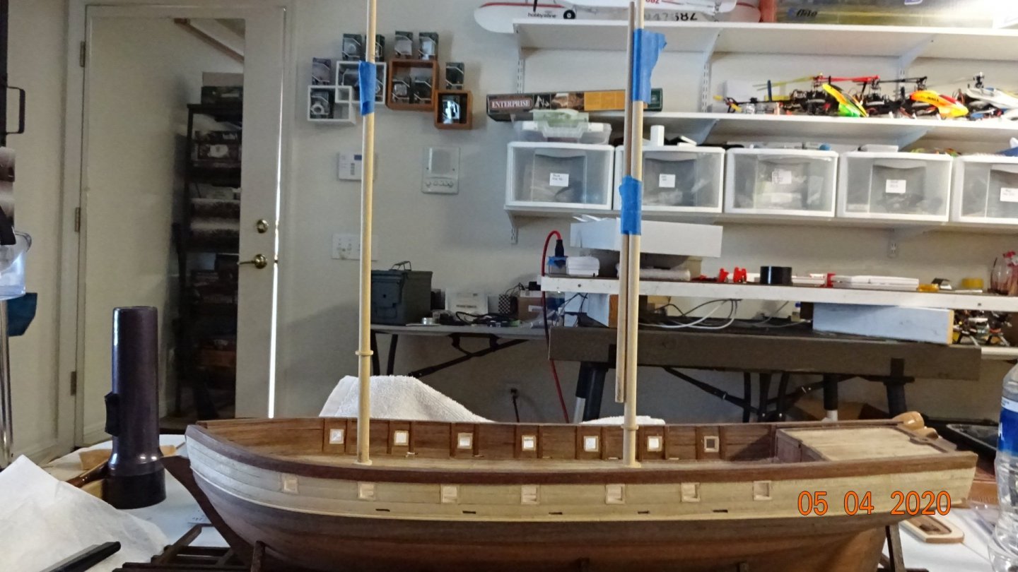

- 195 replies
-
- 5
-

-
- enterprise
- constructo
- (and 1 more)
-
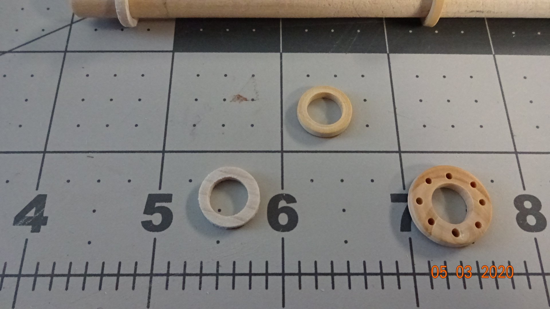
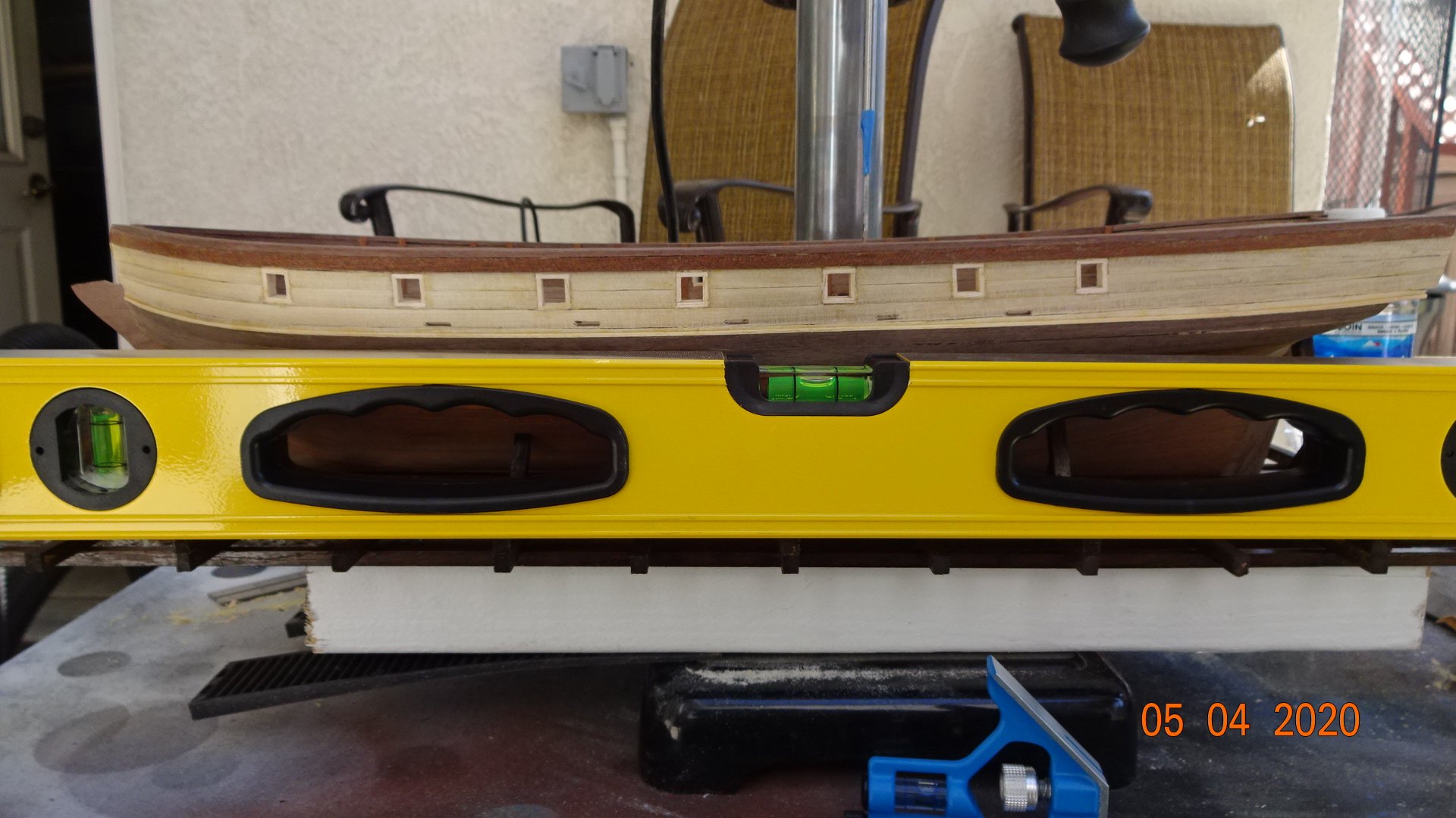
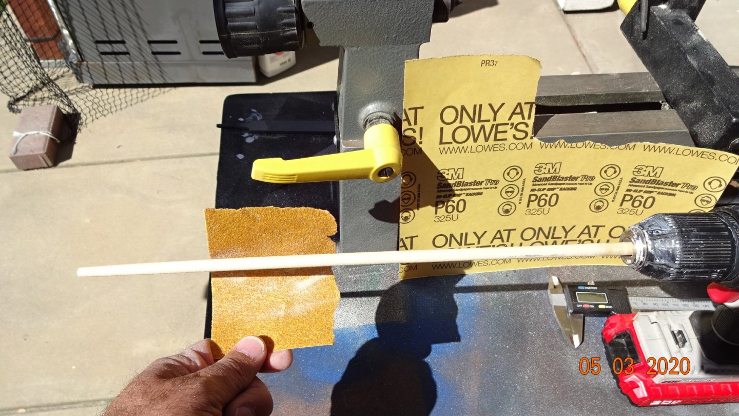
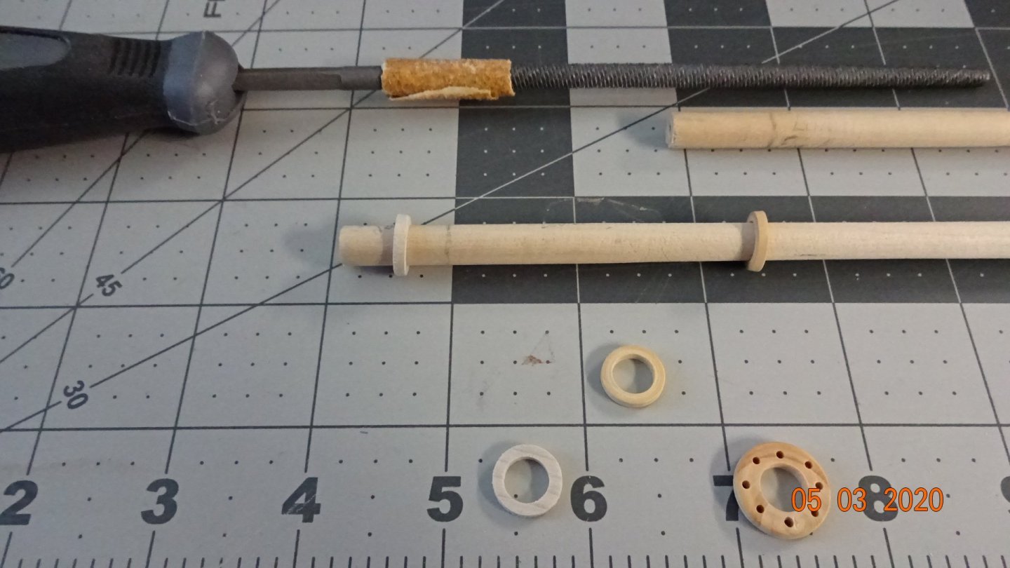
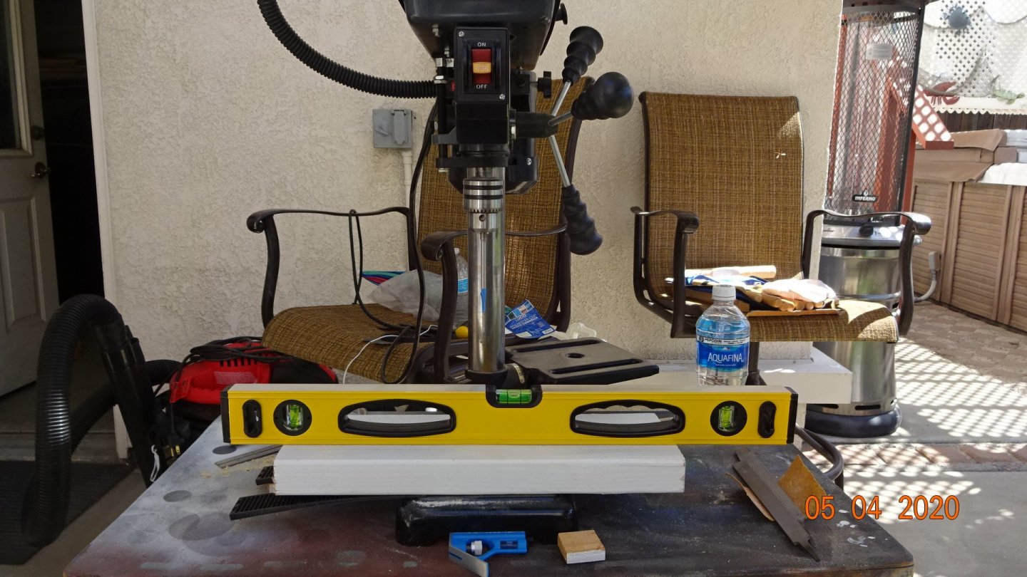
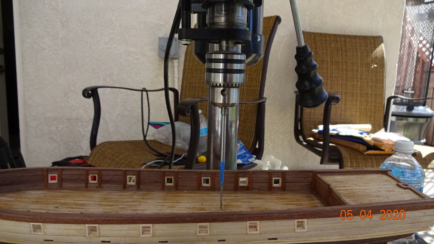
Chris and Sam, Thanks for the input on cannons and their carriages. I will attempt to make some wheels, axle and a little redesign and see what it will look like. Currently though I'm building the masts. This time I just used a drill and sandpaper as opposed to the lathe. Turns out the drill was much faster. On the masts my kit was missing the round pieces that meet where the deck and the mast join. Ended up making my own, to get the center I just used the original to mark the circle and then drilled pilot holes all around the marking. Used the xacto knife to cut the center out and sanded. Mine is the one on the square between 5 and 6. Test fitting shows a good job. On to the mast holes for the ship. I initially pre-drilled small holes when the decking went on so I know where they go. Not sure when is the correct time to drill the mast holes completely, I just chose this time. I used a drill press for accuracy. First I started with a level surface. Then I added the ship. Then I crossed my fingers and drilled. The blue tape on the drill bit is my mark as to the farthest I want to drill.


- 195 replies
-
- 4
-
-
- enterprise
- constructo
- (and 1 more)
-
Chris and Sam, Thanks for the input on cannons and their carriages. I will attempt to make some wheels, axle and a little redesign and see what it will look like. Currently though I'm building the masts.
- 195 replies
-
- 2
-
-
- enterprise
- constructo
- (and 1 more)
-
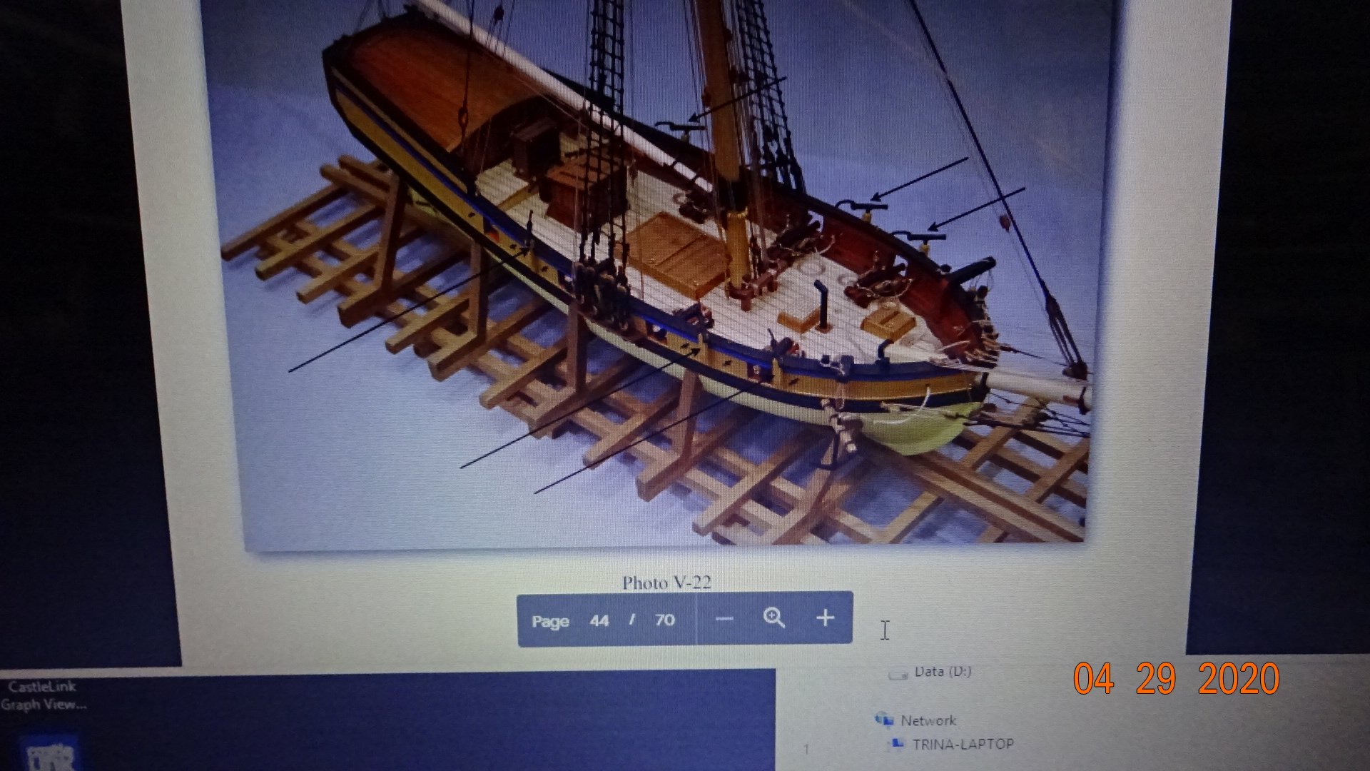
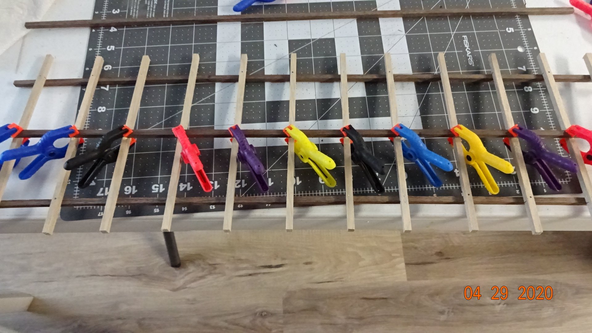
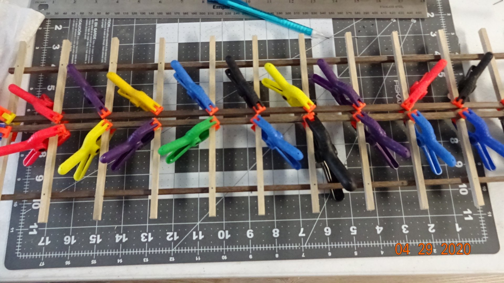
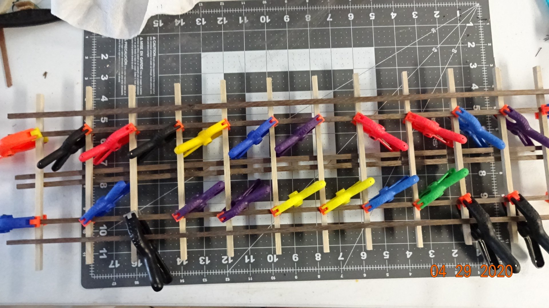
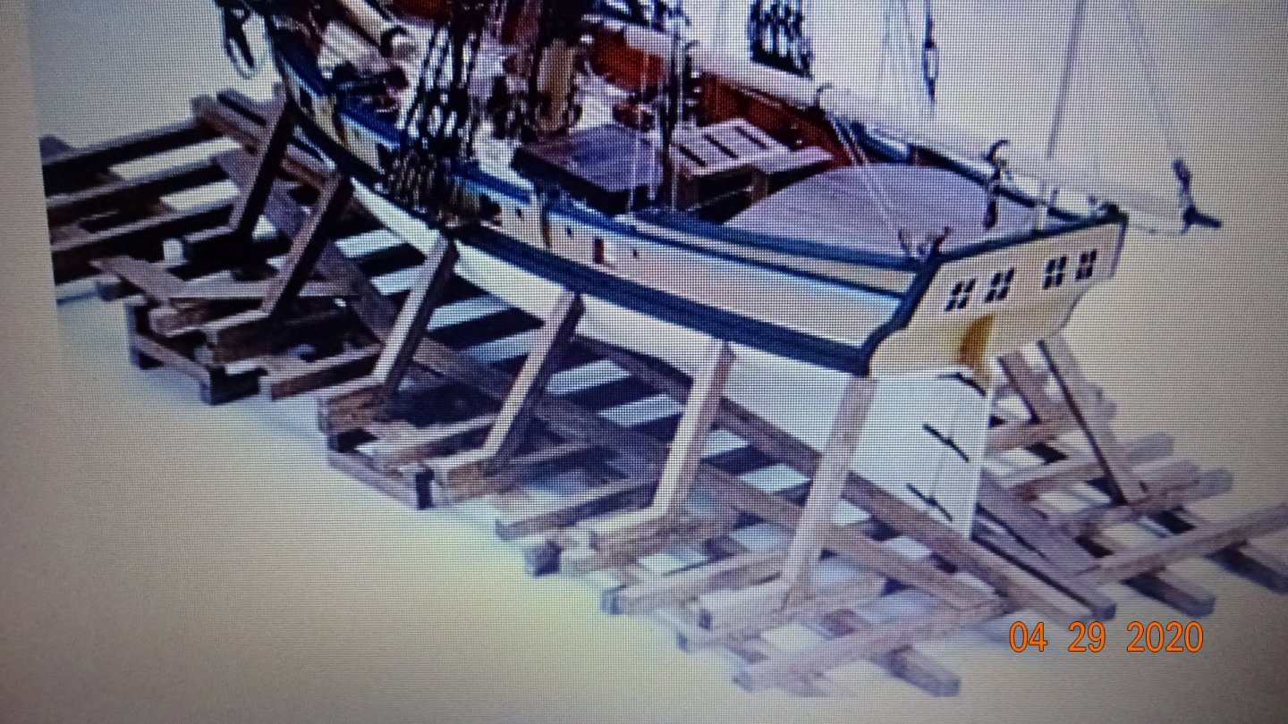
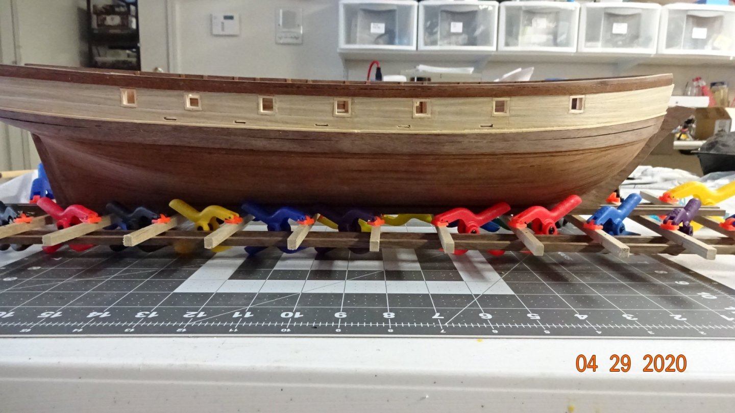
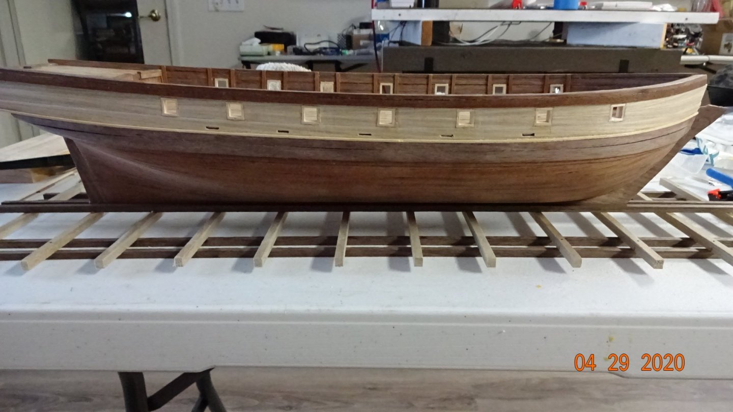
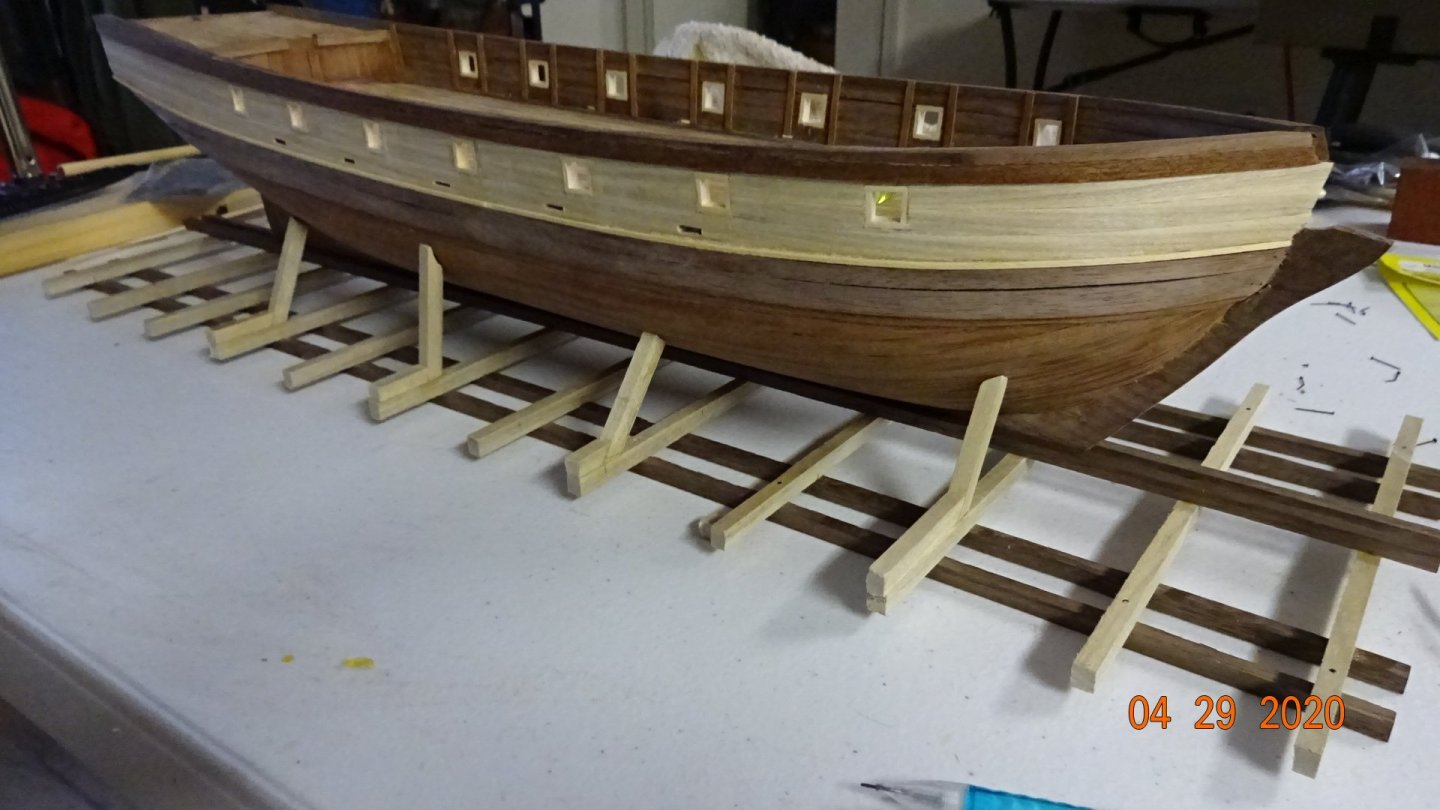
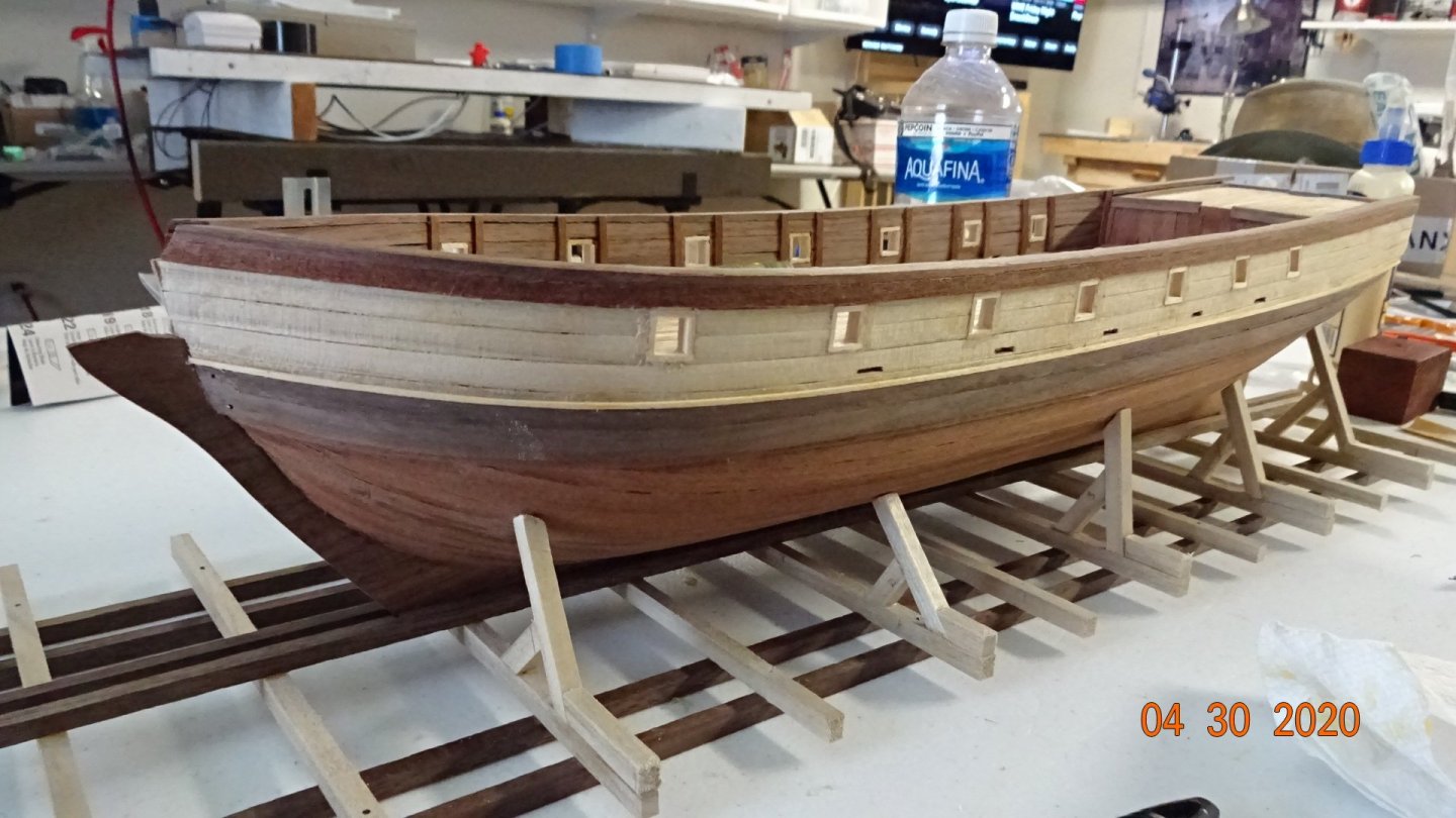
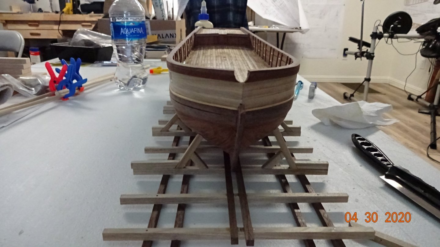
Decided to change up things and have some fun. I wanted a docking station/ship holder thingy.... lol. After looking around I found something I liked. Took this picture off the web and thought it would do both, hold the ship and act as a docking station. Here's my progress after a few hours. I should have taken more pictures as I developed this docking station, but didn't think about it till now. Here's another image from the web of the design I'm working towards. Those images motivated me to keep going. Once this dries it's ready for the ship Testing if the keel fits my dock. Finally the glue dries and the clamps come off. Well, how did I do? Wait, you thought I was done. No way, need some support timbers. Both sides now have supports beams. Now my ship has a place to call home. Still needs some finishing touches but I'll get to that later. It took about 3 days working 4 to 5 hours a day. I had a lot of fun and enjoyed the project. Later mates ......


- 195 replies
-
- 6
-
-
- enterprise
- constructo
- (and 1 more)
-
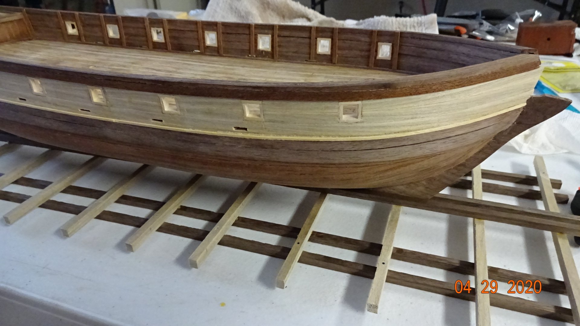
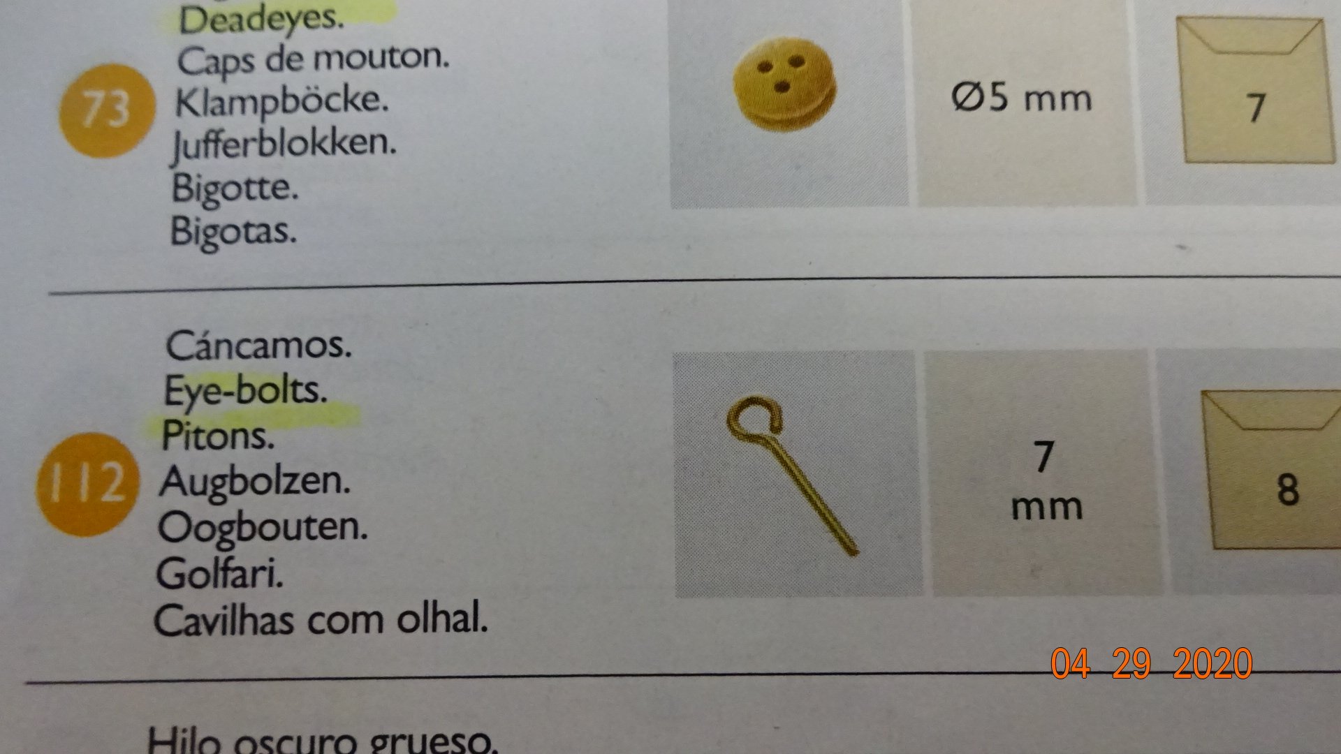
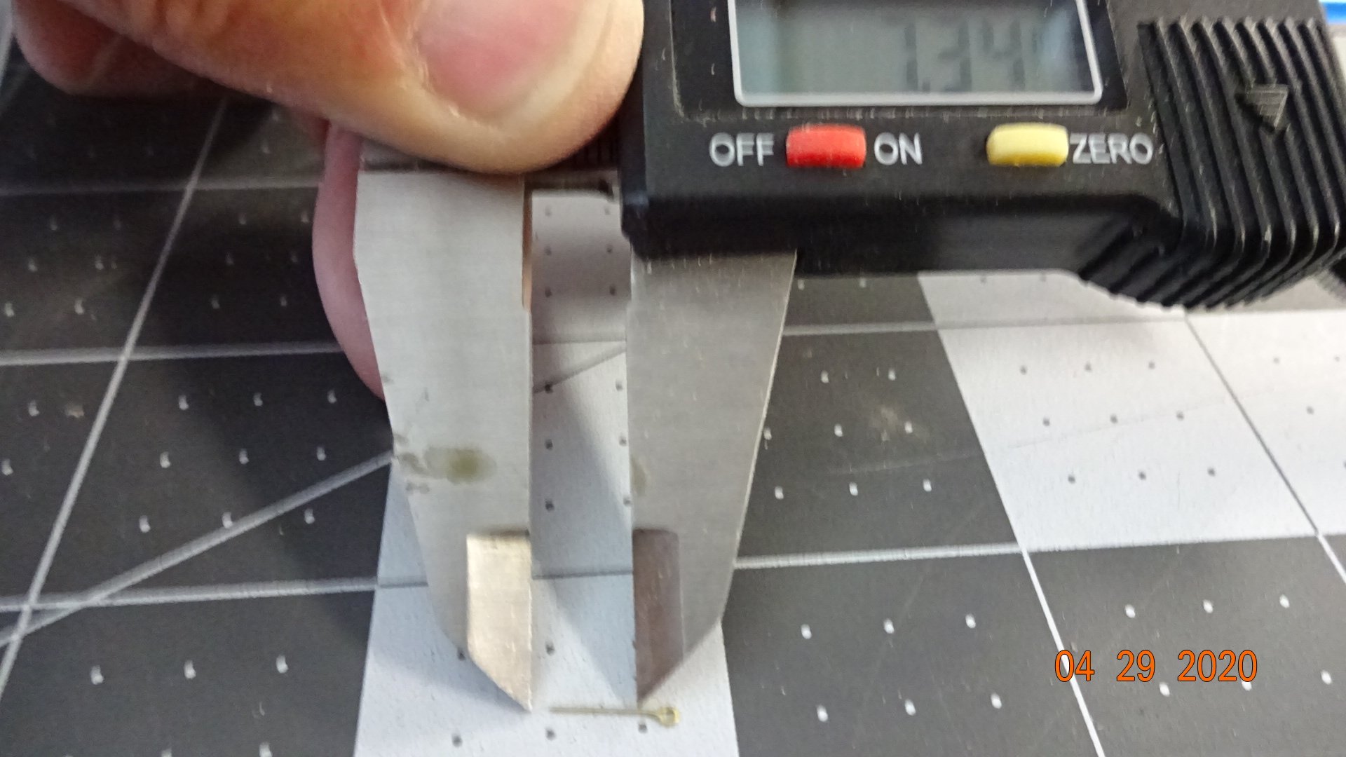
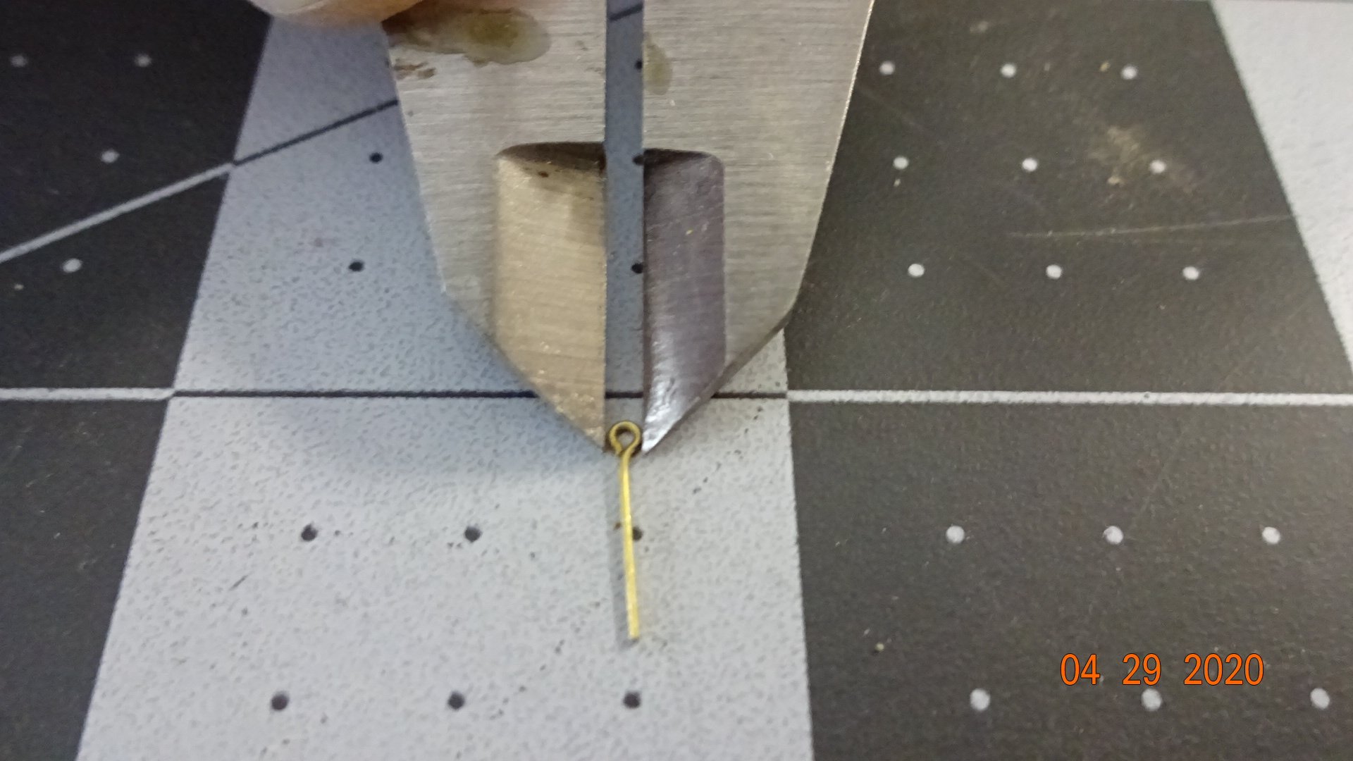
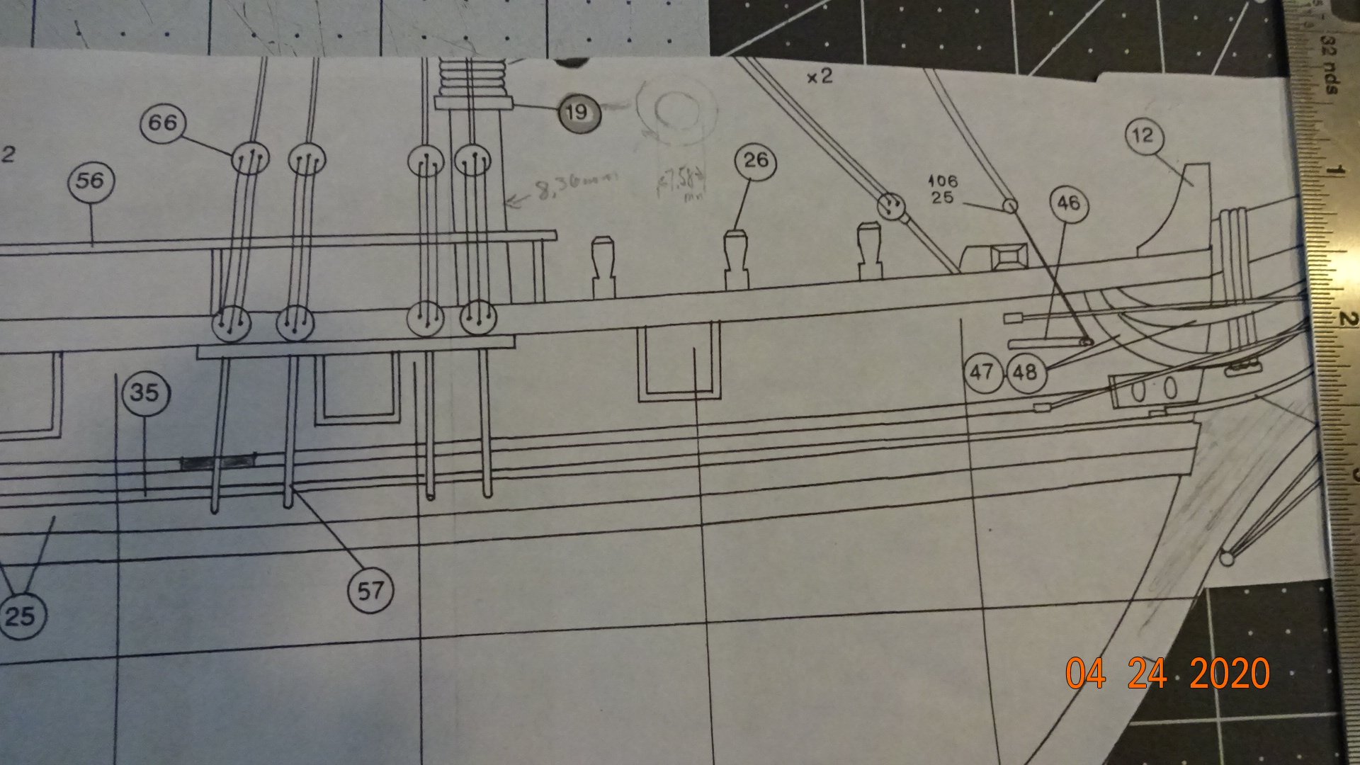
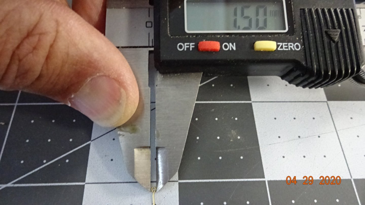
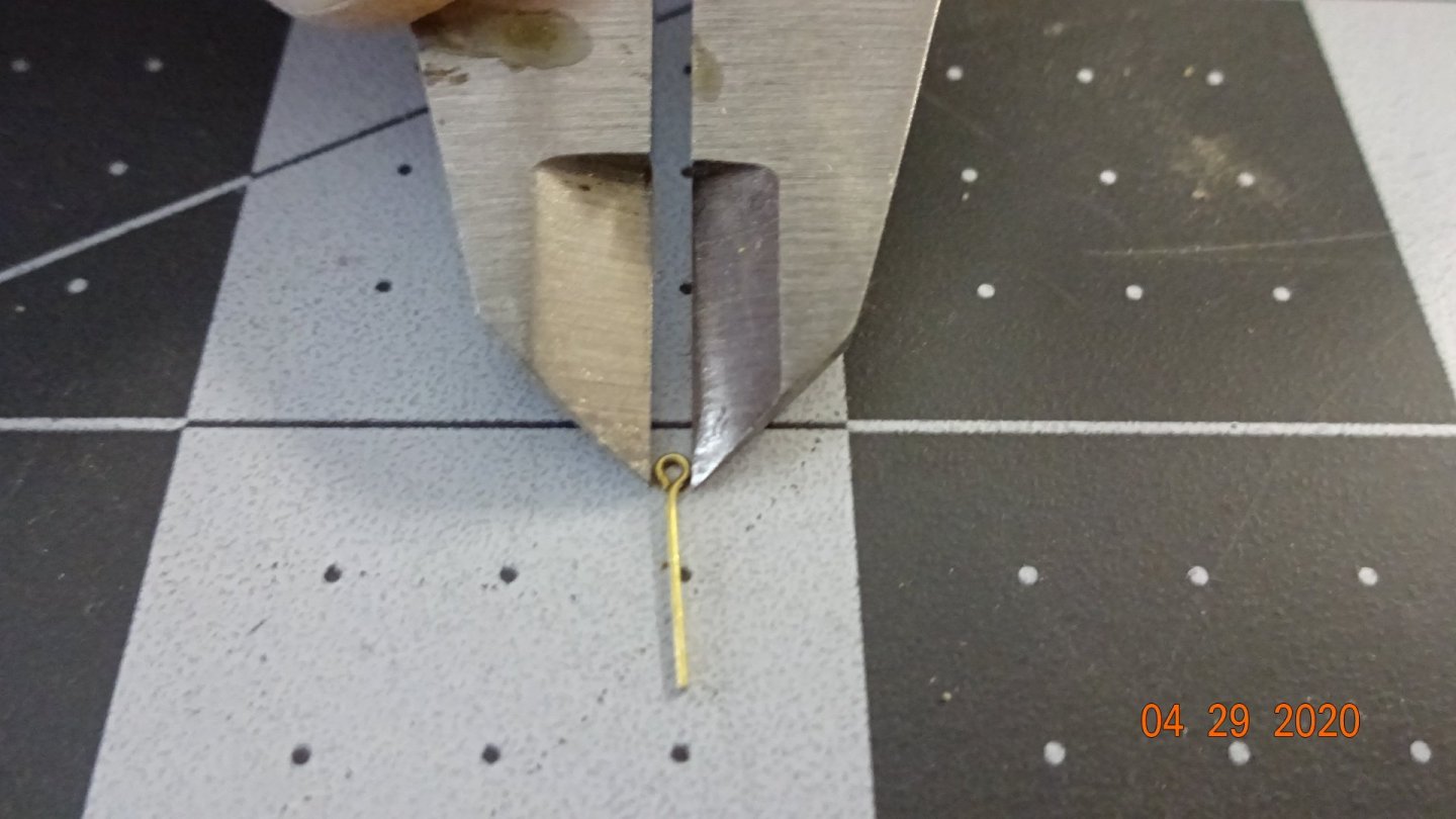
Next I need to put some eyebolts in the bowspirit. Here's what the manual calls for. Here's what I got in the kit. ..... 0 , nada, nothing ! Actually I did find some in a back, not enough for the entire build but enough to start. Since the manual shows the size as 7mm , I ordered some. Only they are 9mm total, 7 mm to the eyebolt and very small. Not sure if these are the right size, Any one have thoughts? There is an issue with font size and underlining of text on this web site. Not sure why it happens but sometimes this app underlines my text and/or changes the font size. Maybe an administrator can look into it. Between the cannons and now the eyebolt's I'm ready for a change.,


- 195 replies
-
- 4
-
-
- enterprise
- constructo
- (and 1 more)
-
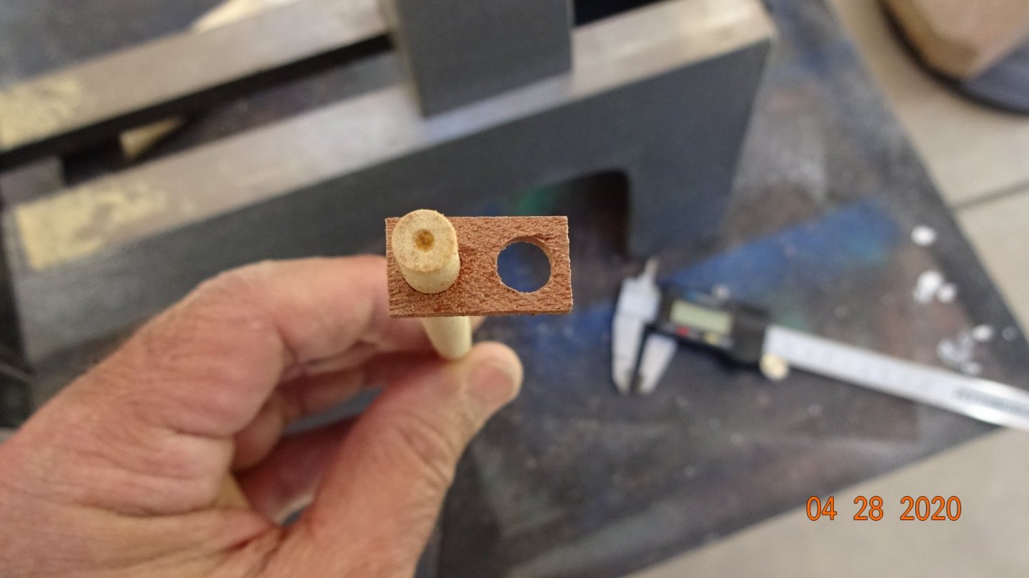
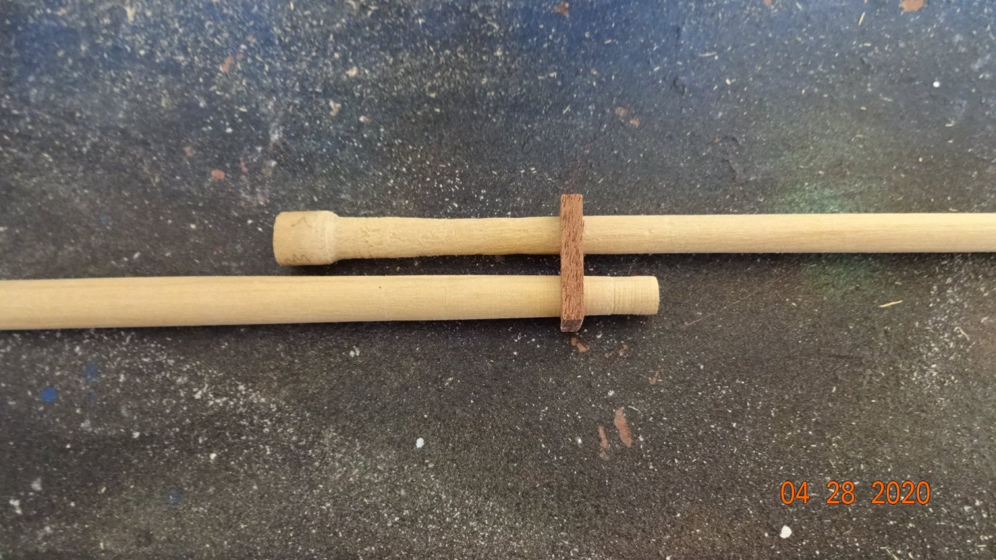
Some information on cannons discussed that the carronade cannons were typically on top deck and the regular cannons below deck. I think I might just make mine regular cannons. I cut some small wheels for dowels and the wheel size looks ok, smaller front larger back wheels. Thus, I know I can make the wheels if necessary. Question: would I drill the holes before cutting or after. If done before, I would be afraid the small wheels would just come apart in the table saw. If done after, holding those small wheels while drilling seems like an issue. I guess I'll figure it out when/if I get around to it. Taking some more time on this issue.
- 195 replies
-
- 1
-
-
- enterprise
- constructo
- (and 1 more)
-
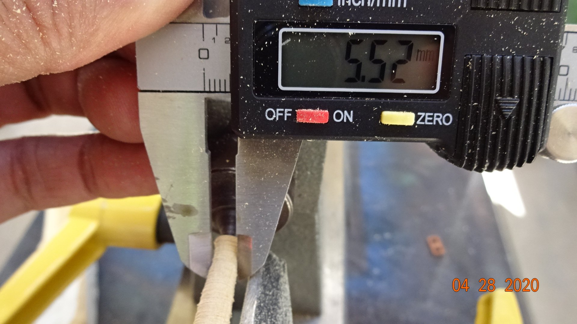
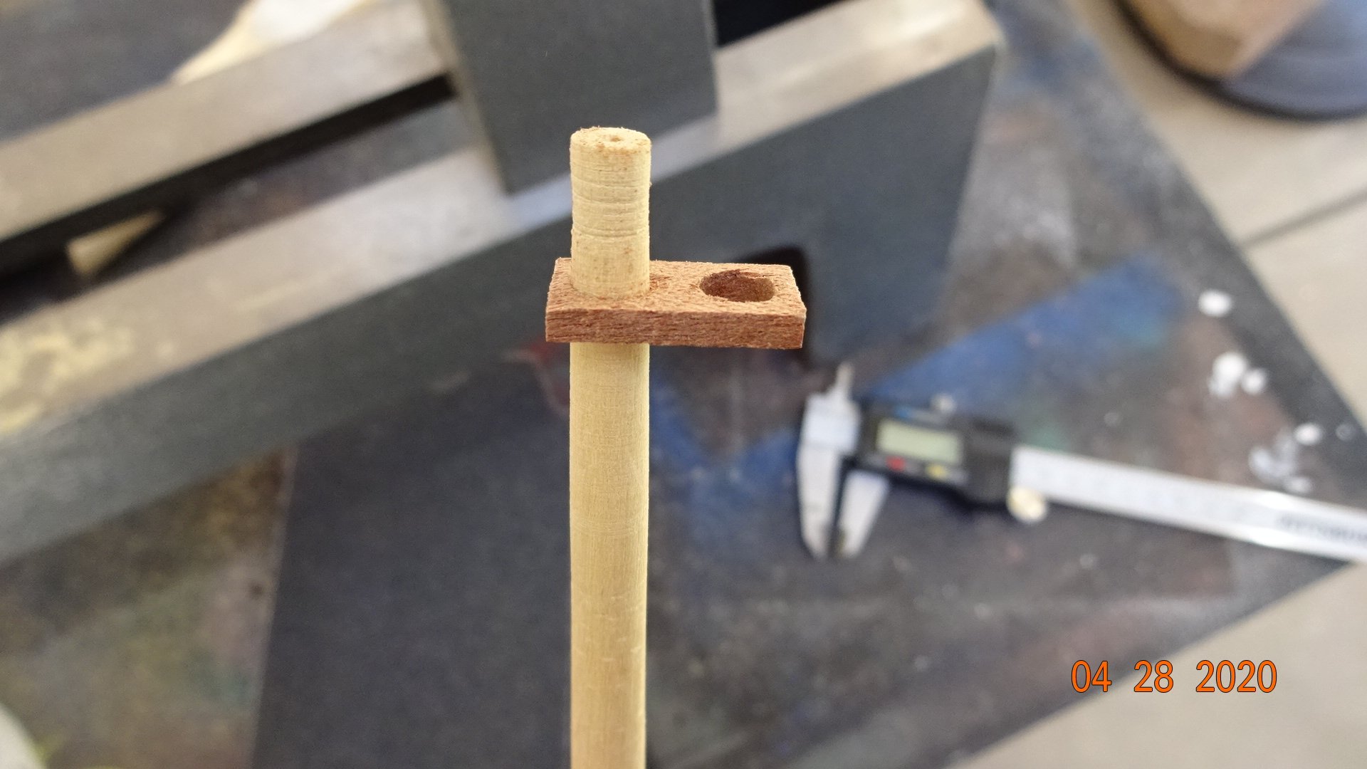
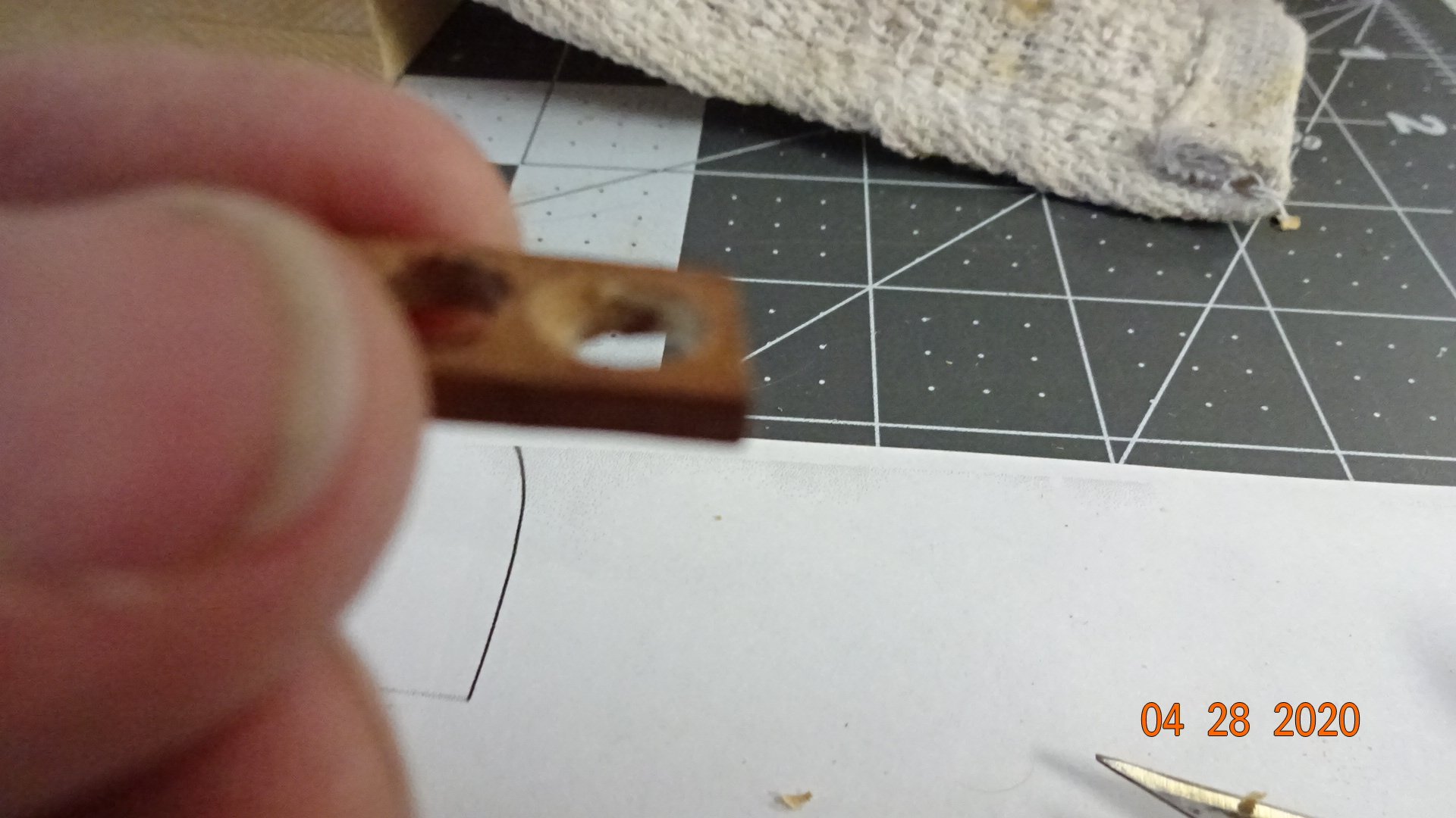
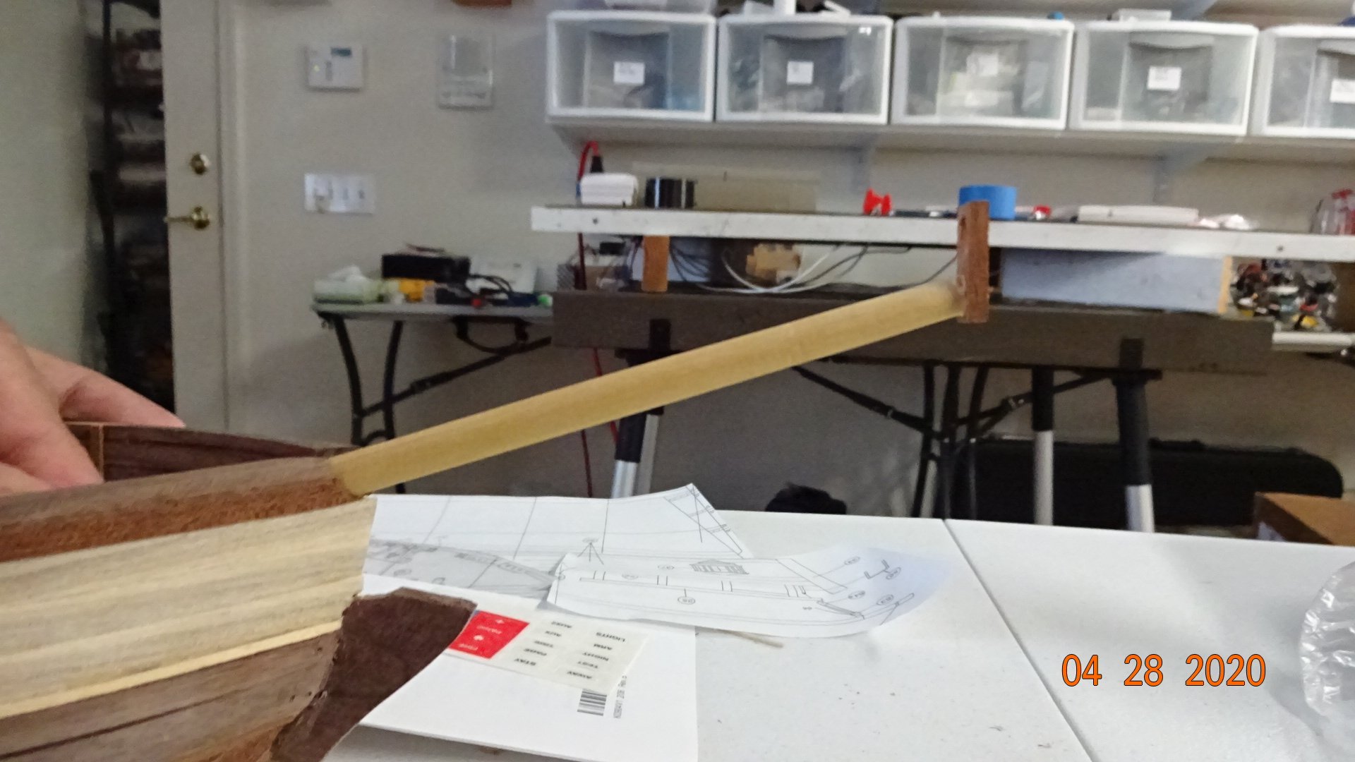
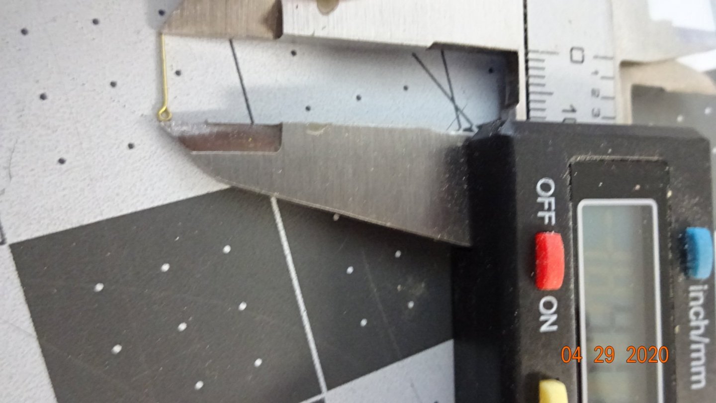
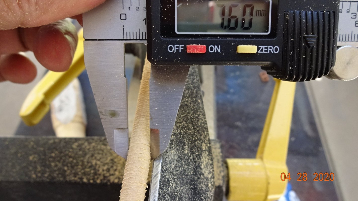
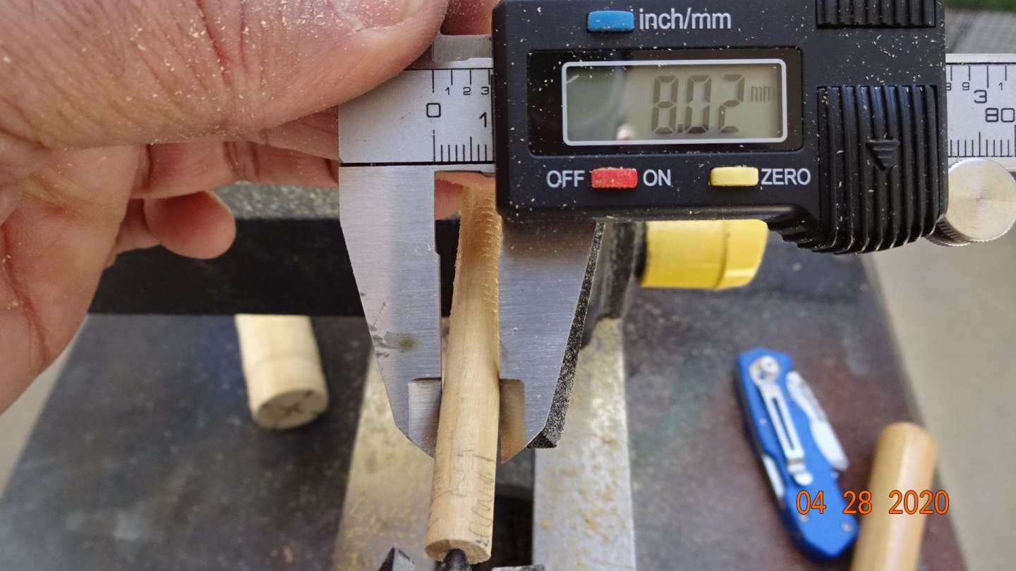
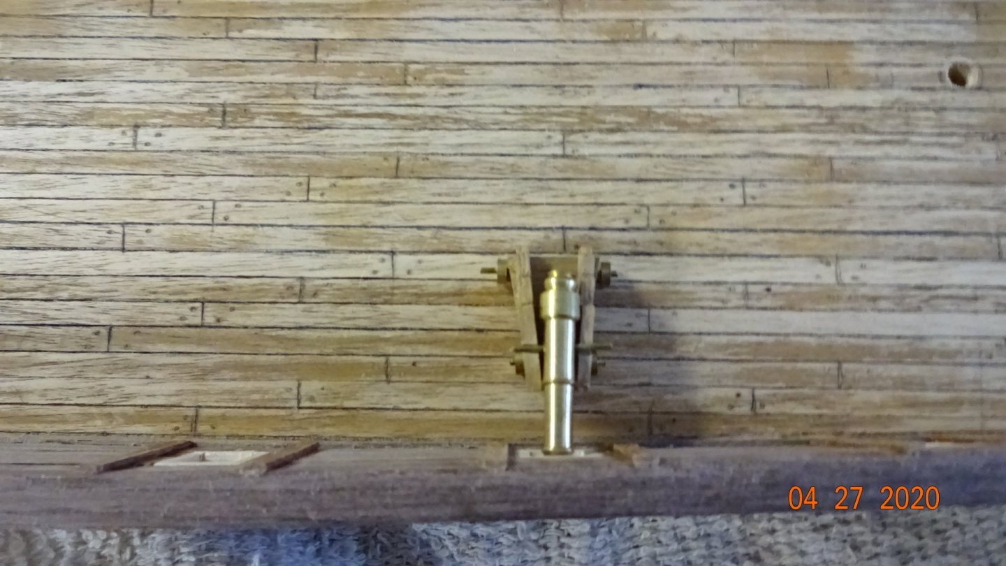
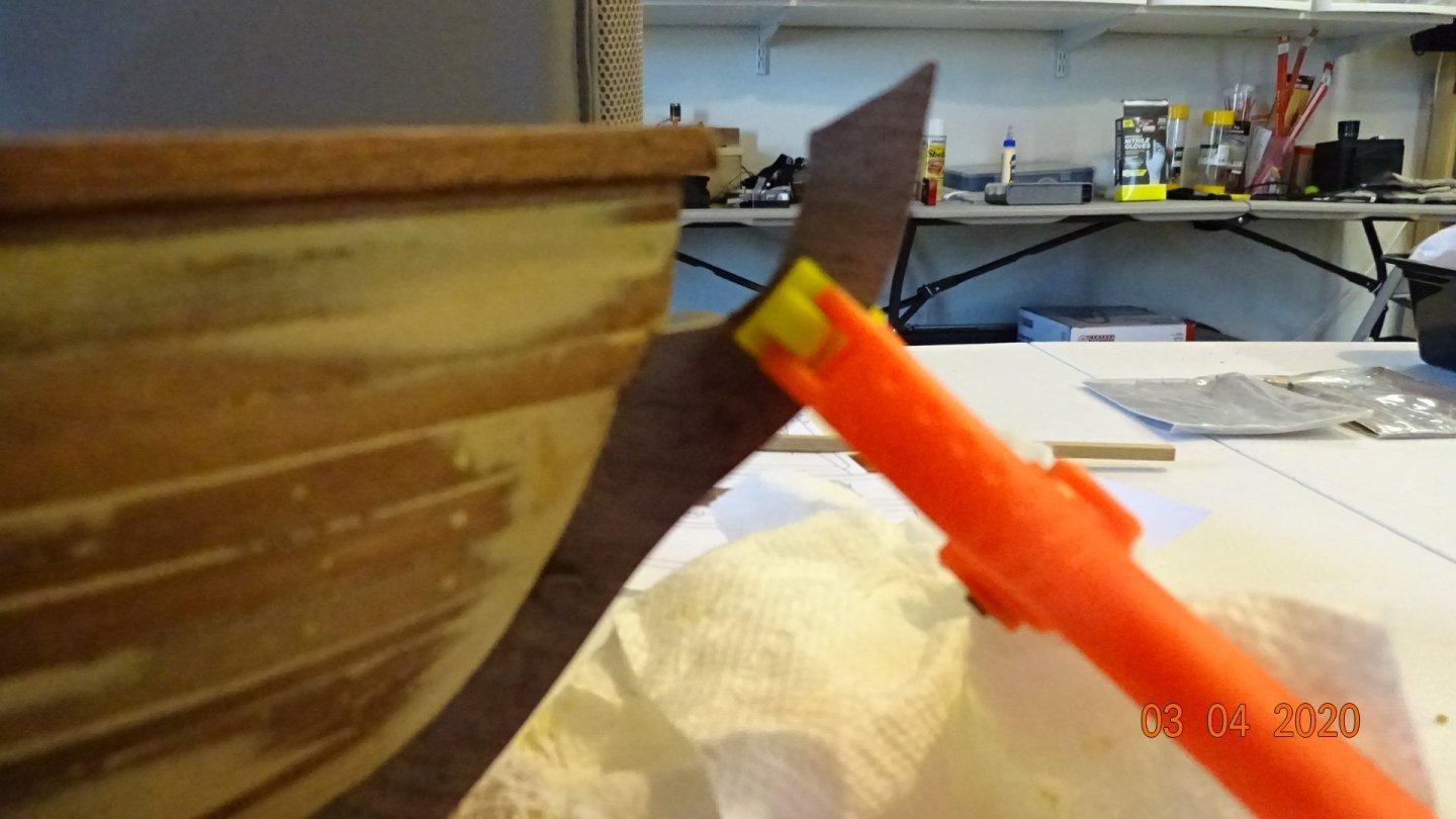
Started working on the bowspirit. The first thing I needed to do ( actually measuring was the first) was to taper the dowels. I have a Harbor Freight table top lathe I purchased a few years ago, never used. So I watch a few videos and started the latheing process. Here's a few pics. Not the best looking bow spirit but sanding helped. Overall it took about an hour but this was my first time. I kept thinking I could hand sand faster. I still have the mainmast and foremast so we'll see if the process goes any faster and looks any better. Here's my first mistake with the bowspirit. Don't pay attention the the larger end piece, I just haven't cut it to off yet. See how nice and straight everything is ...... well that's wrong! Wish the instructions would have described this process better. The pieces actually need to connect at angle so that when mounted the brown connector is pointed close to 90 degrees up and down. When I mounted this unit as is the connector was more like 45 degrees. Here's some pics. Sorry for the blurry image, just showing the angle I needed to cut into both holes. Also the instructions call for mounting 2 small 2X2X5 mm pieces on the bowspirit though they don't exactly tell where they go. This is my best guess. Notice the one near the bow of the boat, I think it's used later when we tie off the bowspirit. Here the connector is much closer to 90 degrees similar to the plans. A litle more sanding and then on to the next step.


- 195 replies
-
- 5
-
-
- enterprise
- constructo
- (and 1 more)
-
Thanks gentlemen for the input. I have to agree, I don't think I would have been happy with those cannons as they are now. I have been doing some investigating and will make a determination later. Bye, Rowboat
- 195 replies
-
- 2
-
-
- enterprise
- constructo
- (and 1 more)
-
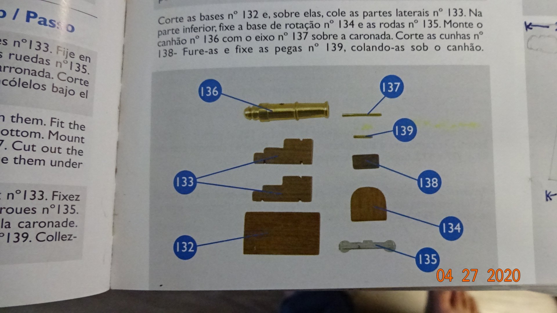
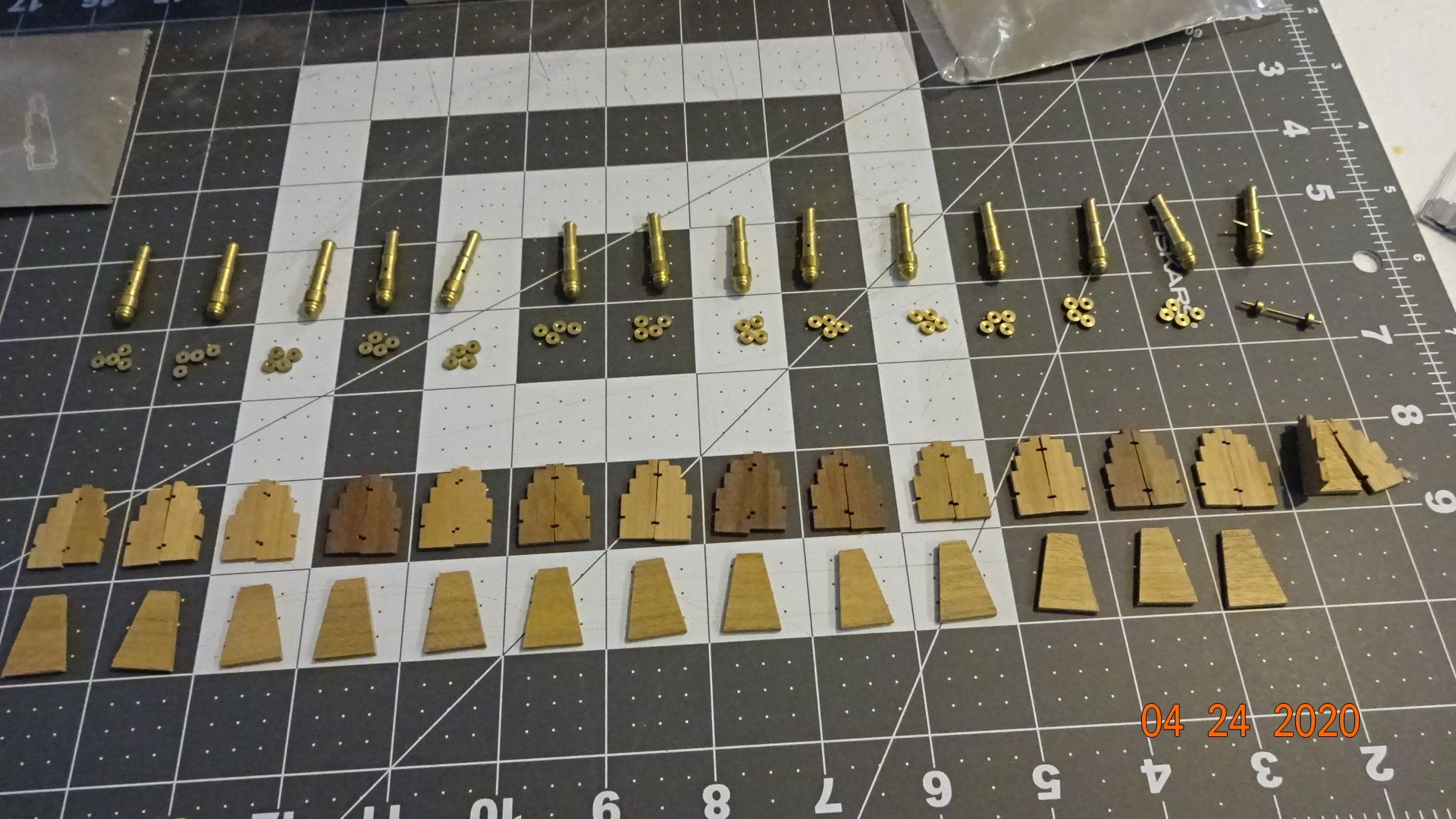
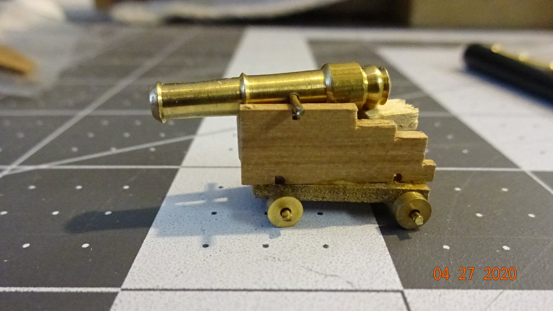
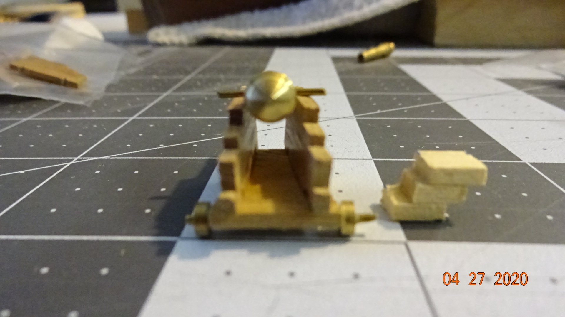
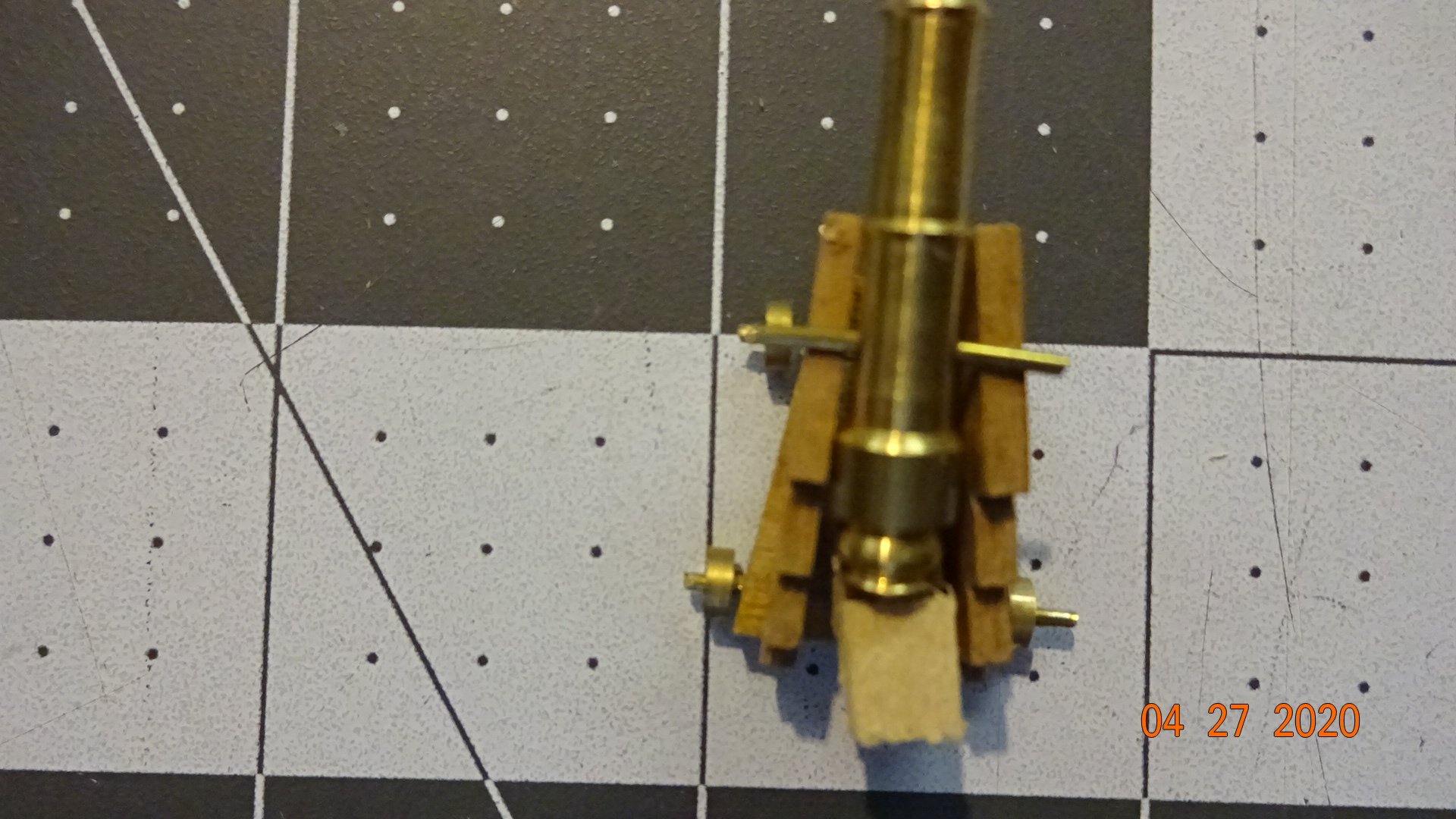
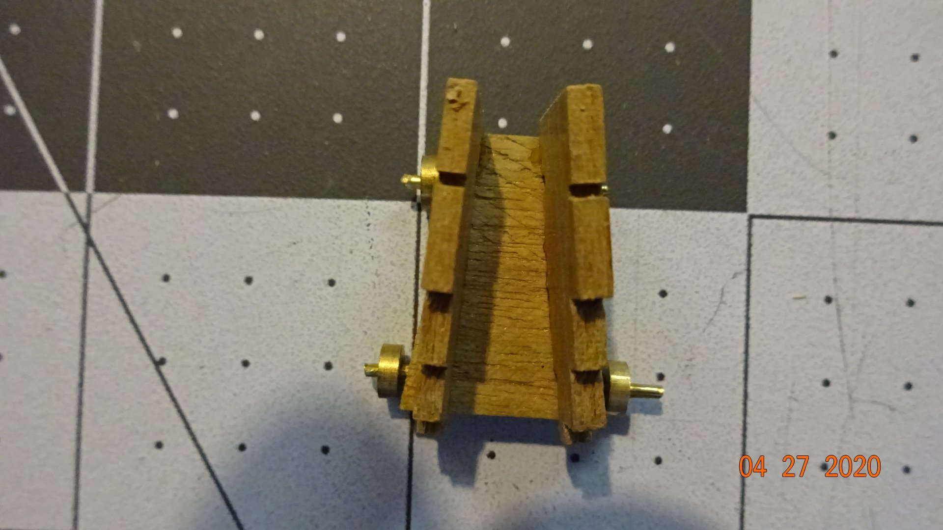
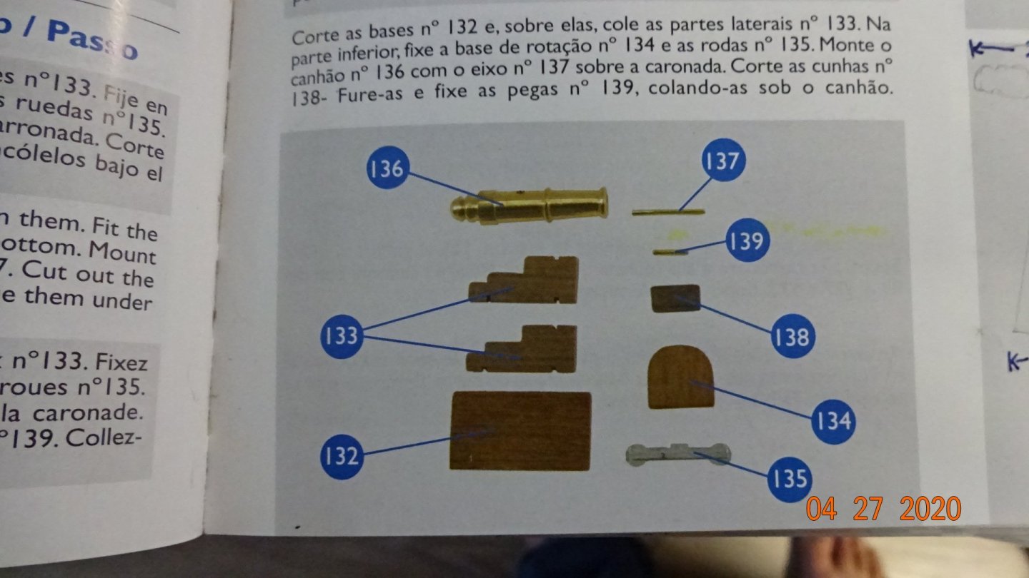
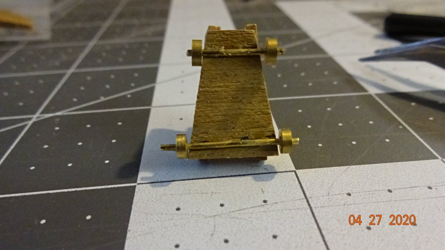
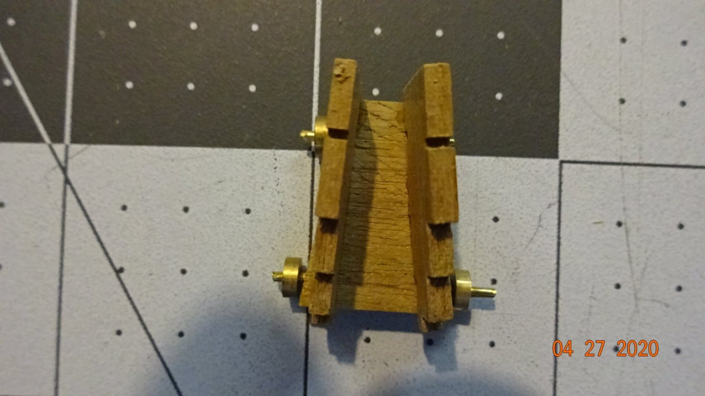
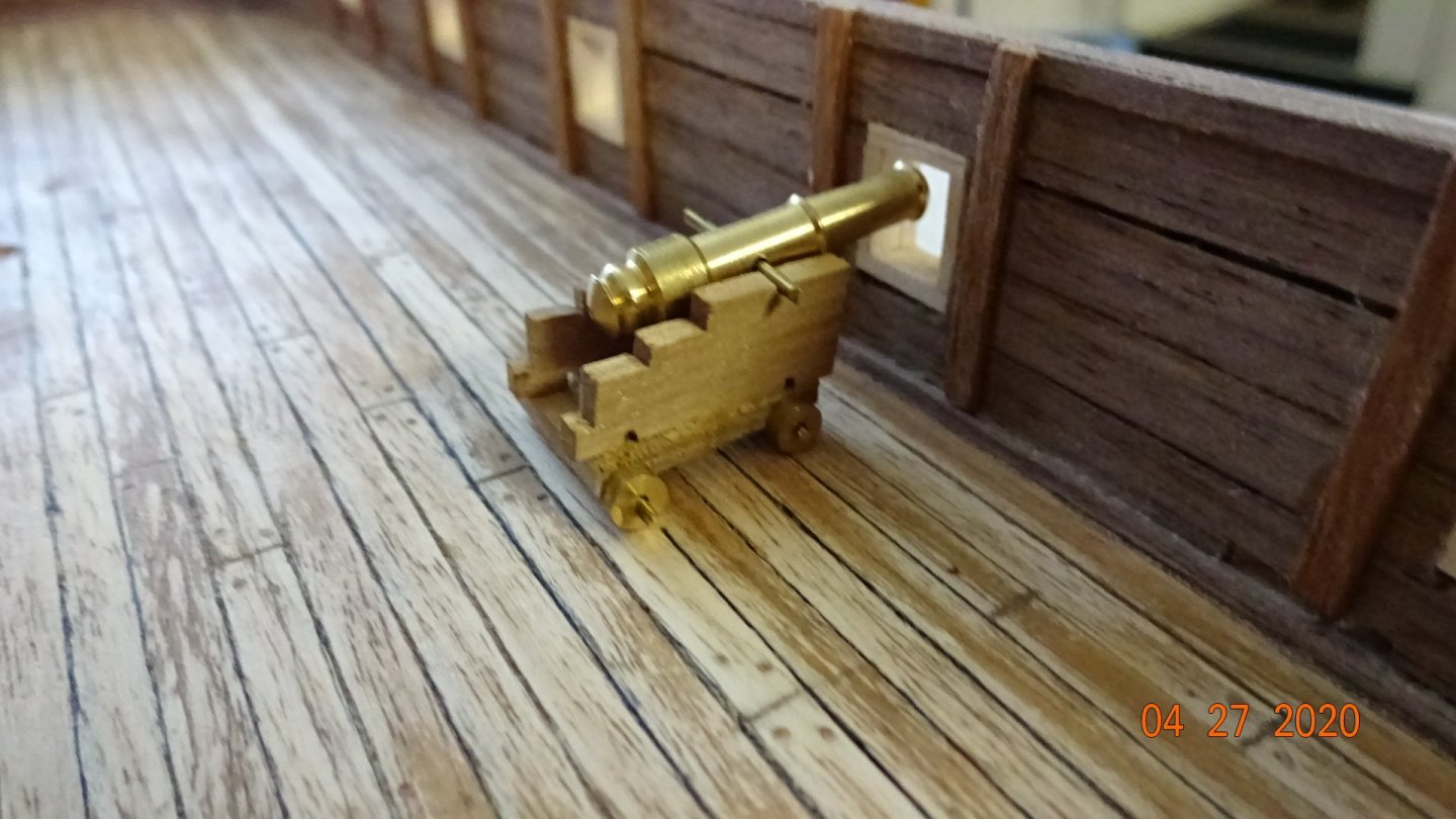
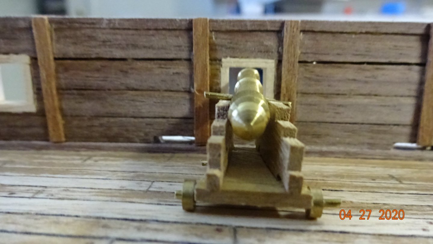
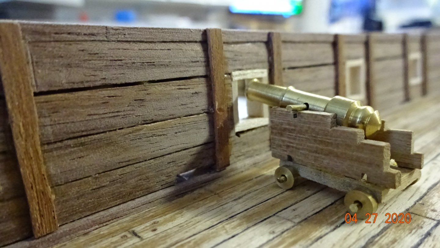
Okay, cannon making .... or not? First the manual image of what should be in the kit. Now, here's what I got. Notice that the base fitting for the carriage is trapezoid shaped not rectangular like the image above. Also the wheels are completely different, worse I'm short 2 wheels ... Not happy about the missing brass wheels as that will be difficult to find. I decided to put one together, here's what I ended up with. I attached the wheels underneath because if I put them on top of the base they would not touch the ground. I am not pleased with the look, any comments? I put it on the ship just to see if it would look and better.... Question: Did they have cannons with brass wheels in 1799? IF so would they be on a cannon carriage? Should I try to get these to work or scrap them and look for a better solution? I think I put them together correctly but it is my first time, maybe I got it wrong. Thanks for any input on this issue. Aye, Aye matey........


- 195 replies
-
- 4
-
-
- enterprise
- constructo
- (and 1 more)
-
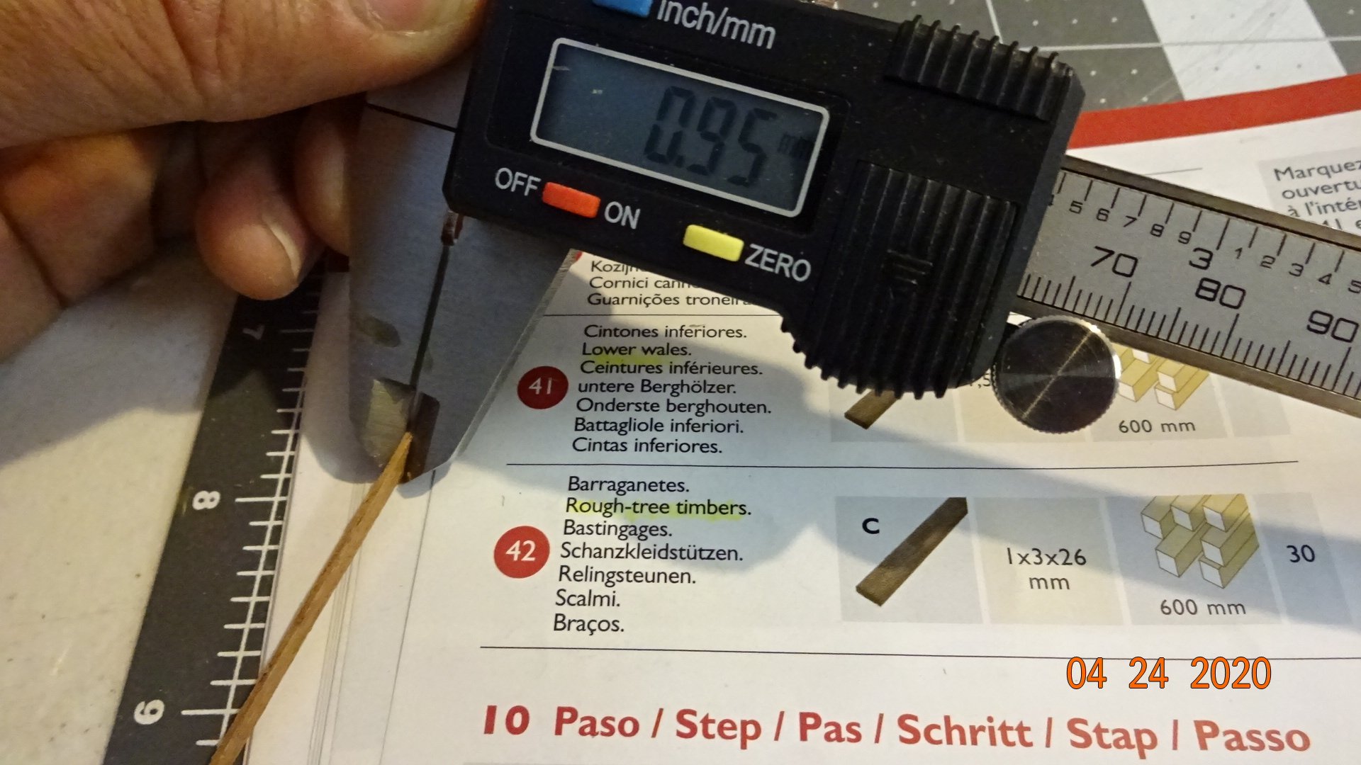
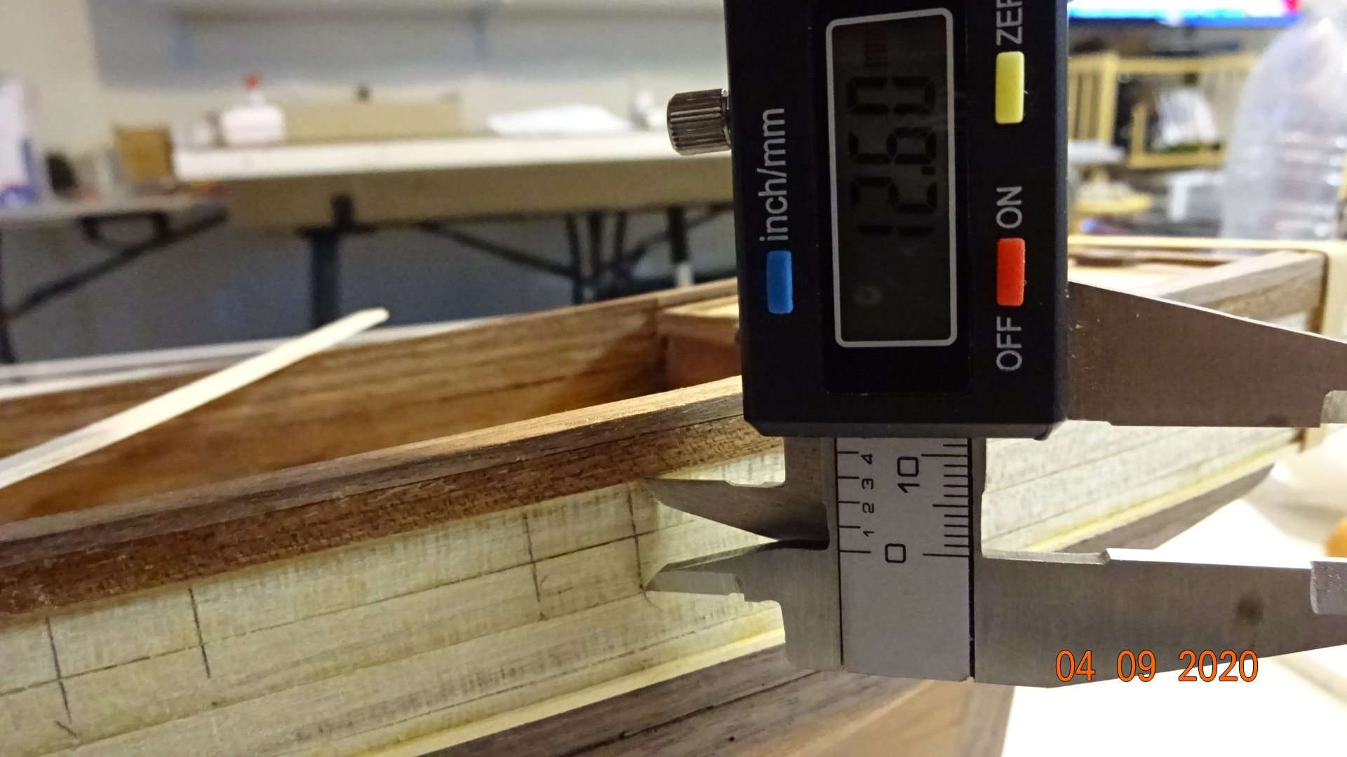
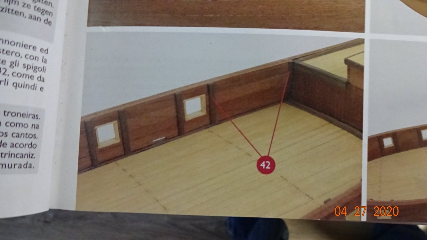
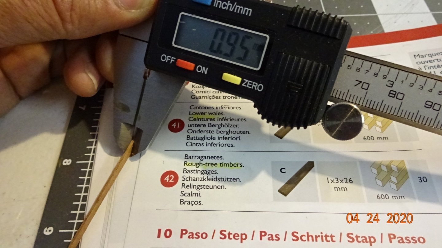
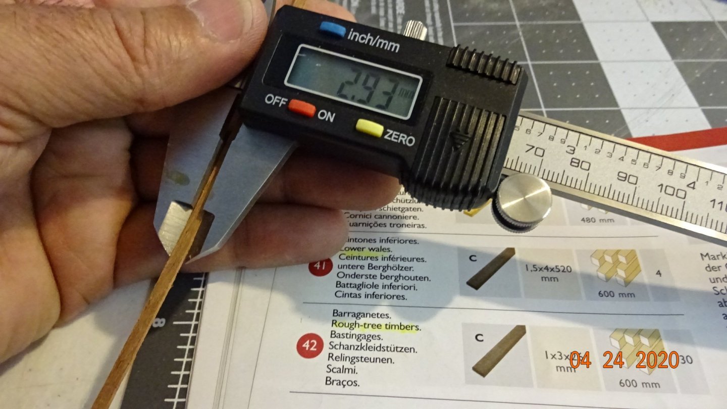
The next step in the manual was add some support timbers around the cannon port holes. The number 42 calls for some wood that is 1mmX3mm. So back to the mill house. This will be close enough. Measure, cut, glue and clamp. Finally the finished look. The inside of the hull had some areas that bowed in so sanding was required before attaching the timbers. Also notice I cut out the scuppers. They had been covered with the second planking and I forgot about them. In the next post I'll discuss the cannon and carriages that came with my kit. Later, Rowboat out.
- 195 replies
-
- 3
-
-
- enterprise
- constructo
- (and 1 more)
-
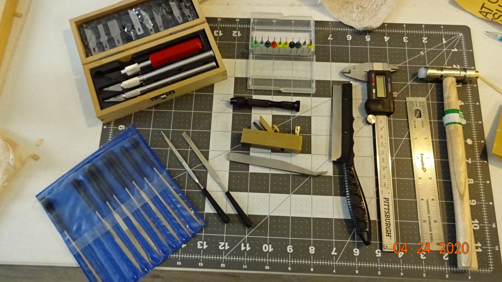
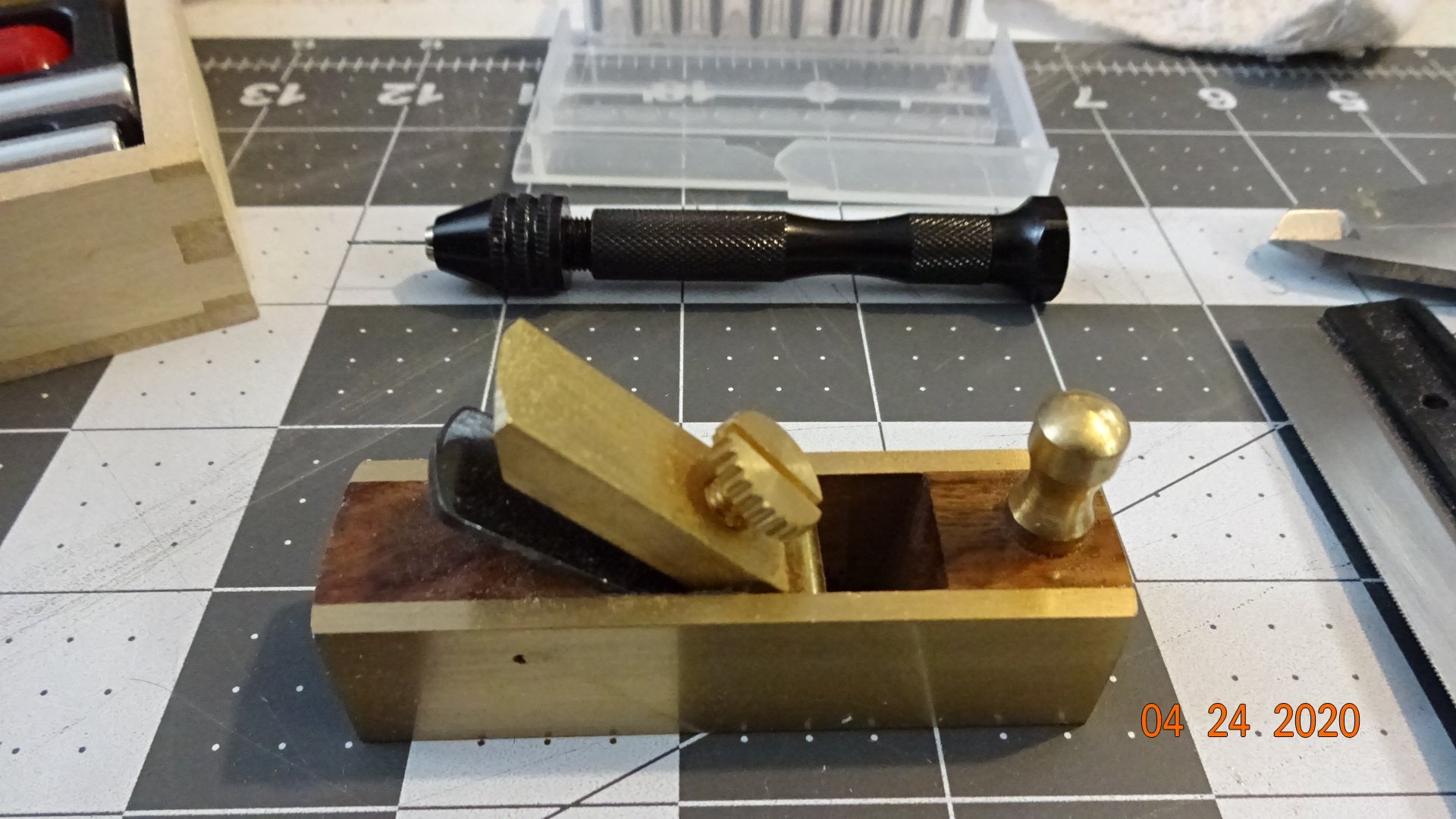
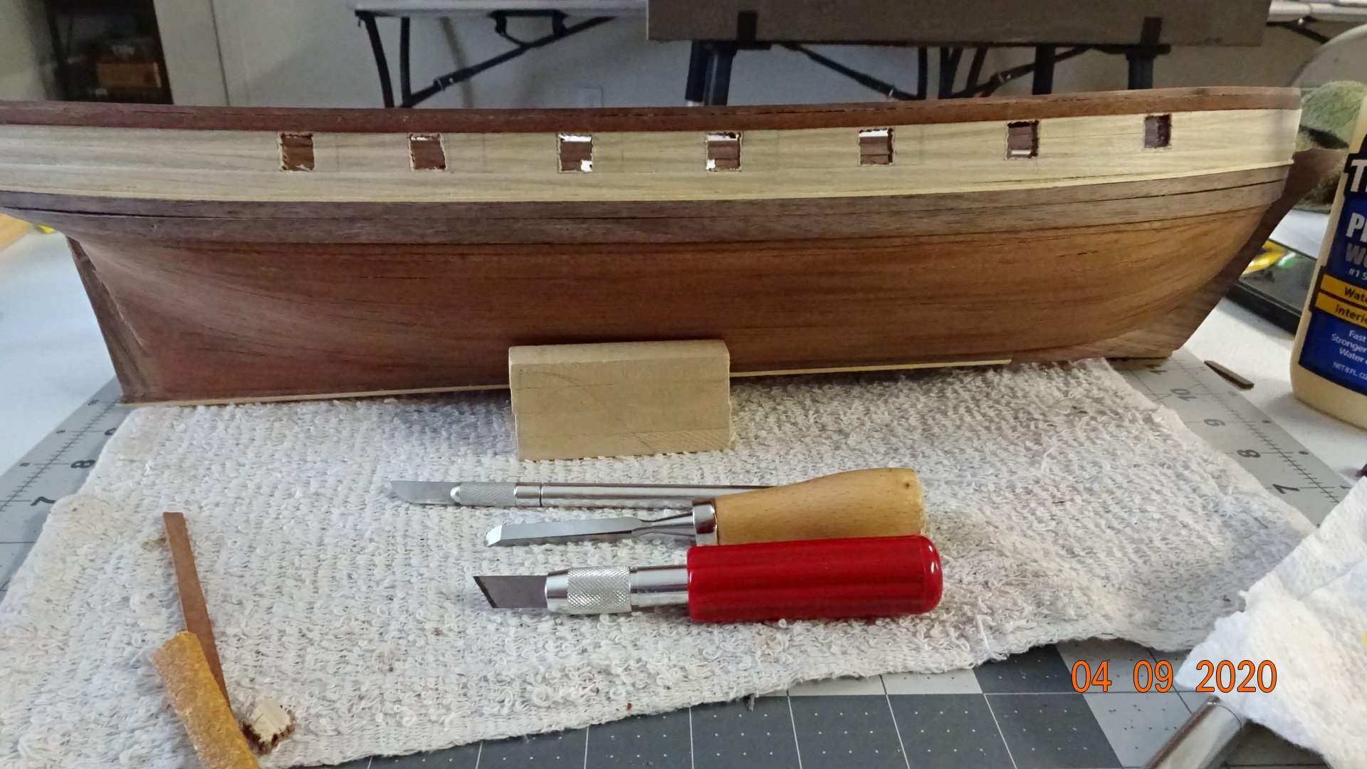
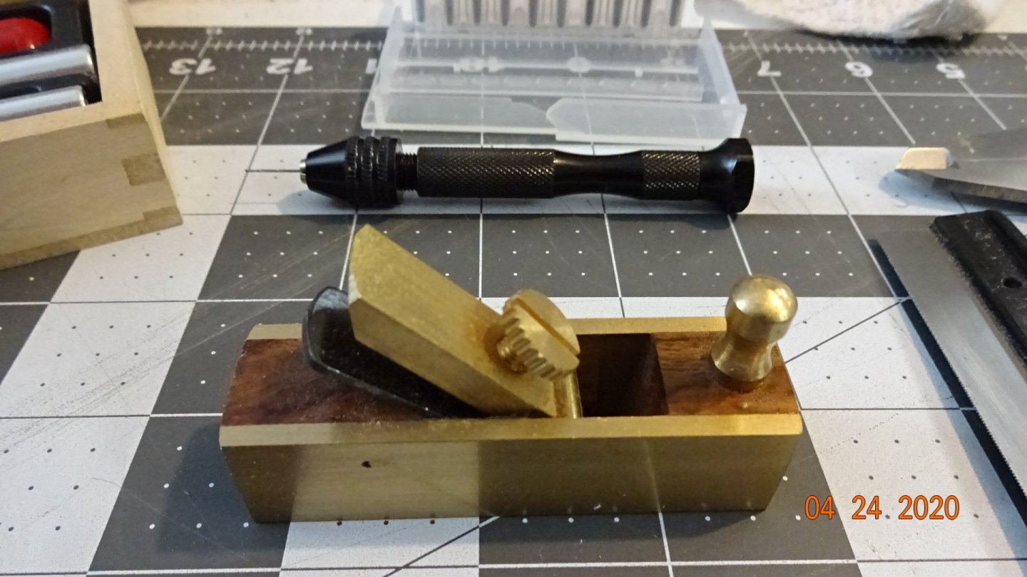
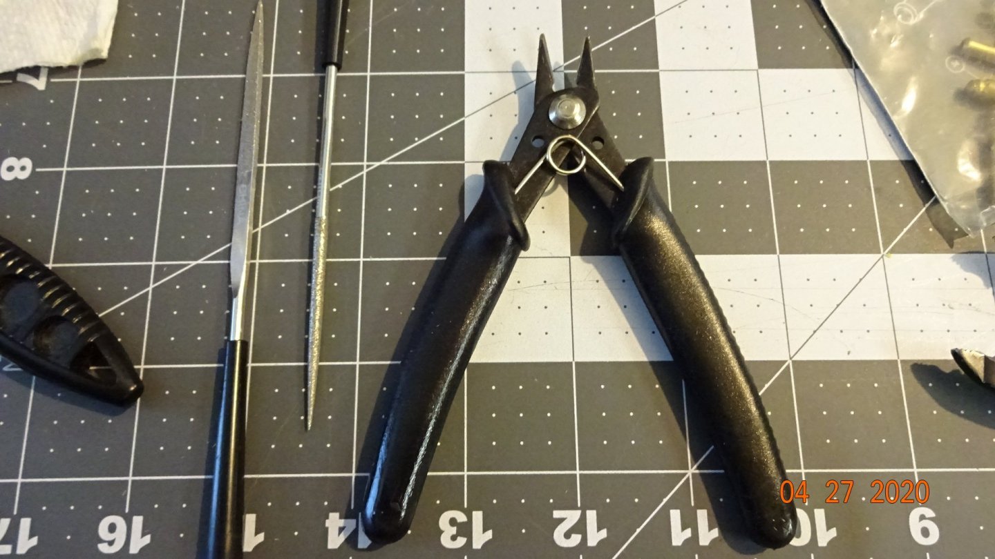
Thought I would post a picture of some of tools I use as a reference to any other newbie ship builders. The costs runs between 5 - 30 US dollars. Most of the tools came from Harbor Freight, the poor mans hobby shop.. The black knife has a fine tooth blade that does a great job of making cuts through the wood. This item I did buy at my local hobby shop and it's worth the $16 I paid. As well, most of the colored clamps in my previous posts came from Harbor Freight. Not advertising for that company just passing on information. These cutters tend to squeeze the wood so don't use them much. I think they are made to crimp the wood so it can bend but I couldn't get it to work like I wanted.

- 195 replies
-
- 3
-
-
- enterprise
- constructo
- (and 1 more)
-
Thanks Sideways, it is starting to come along.
-
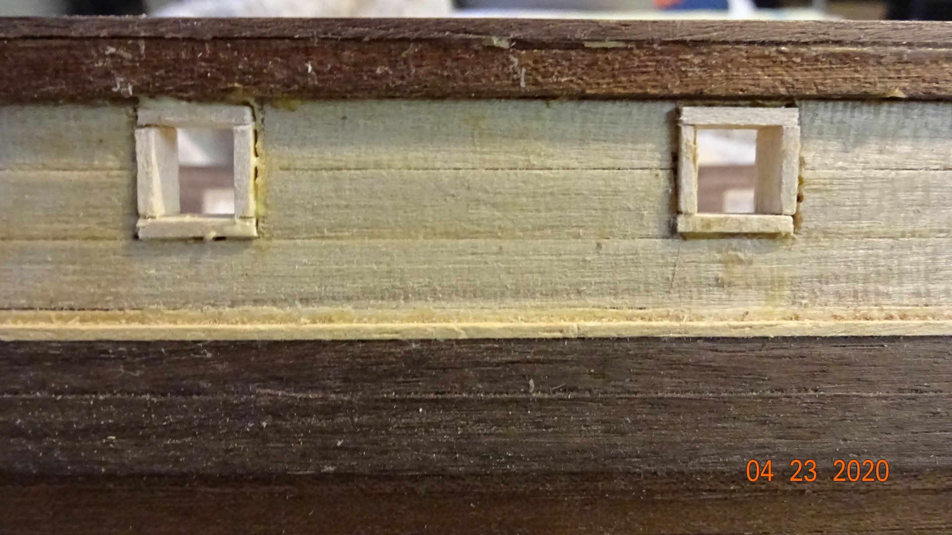
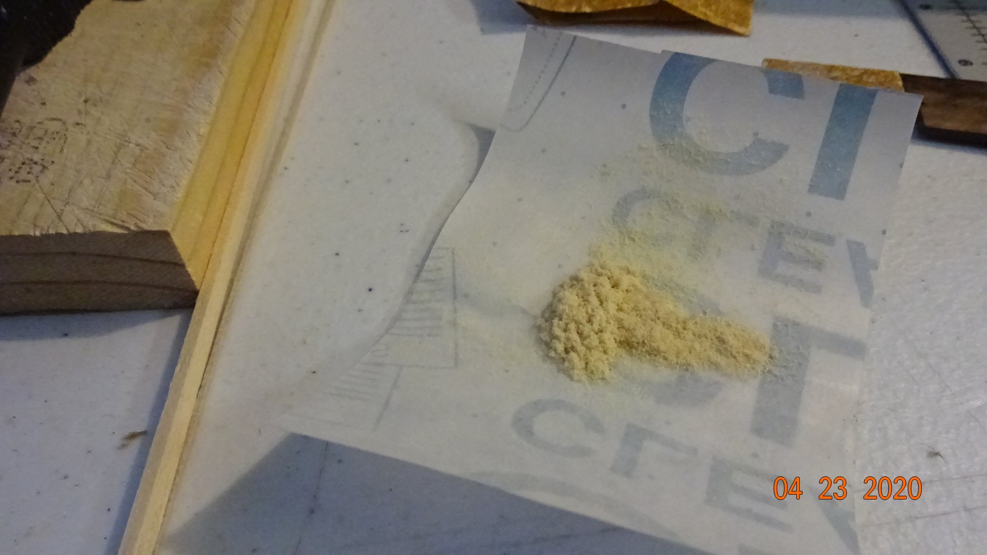
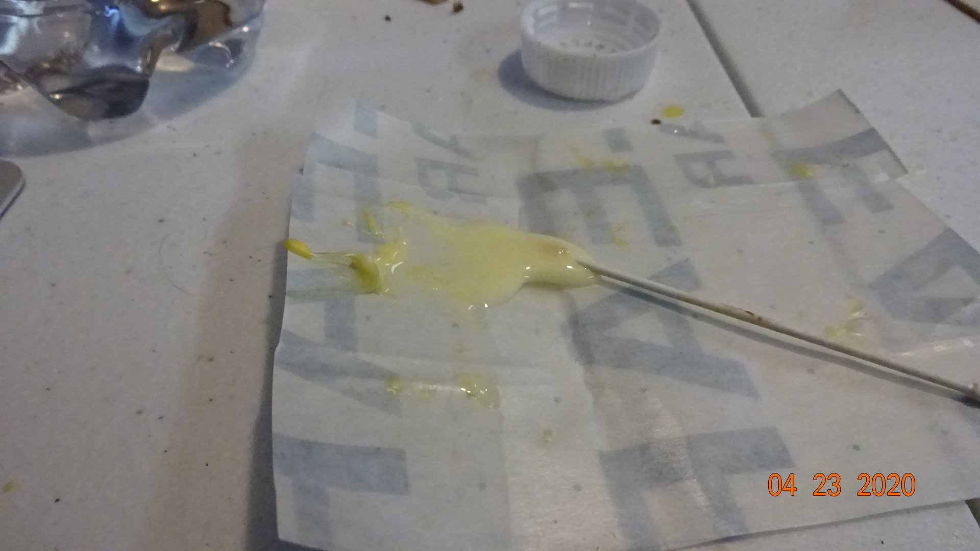
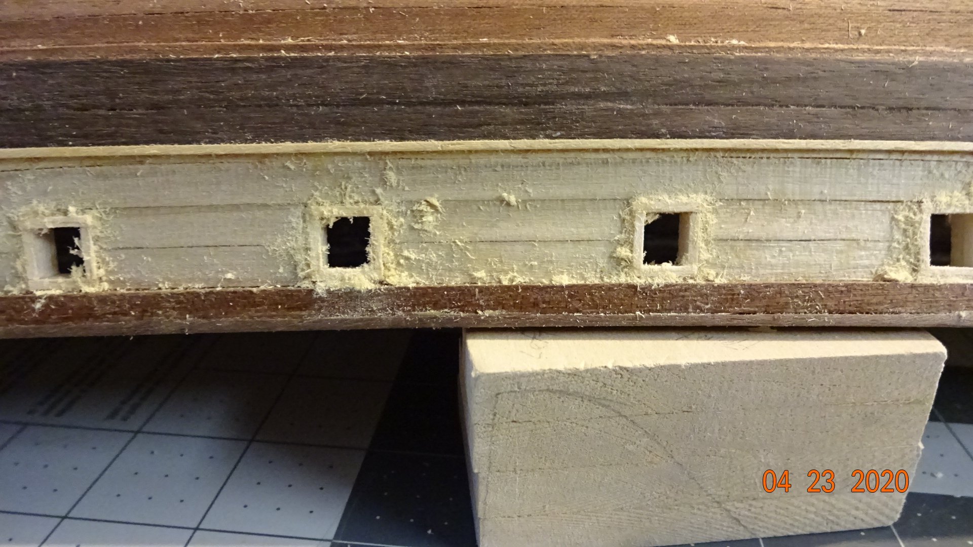
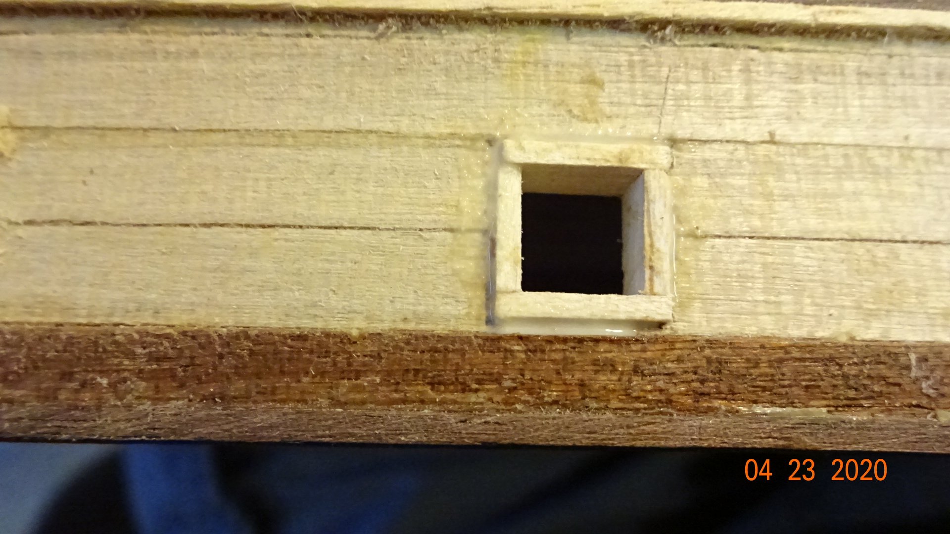
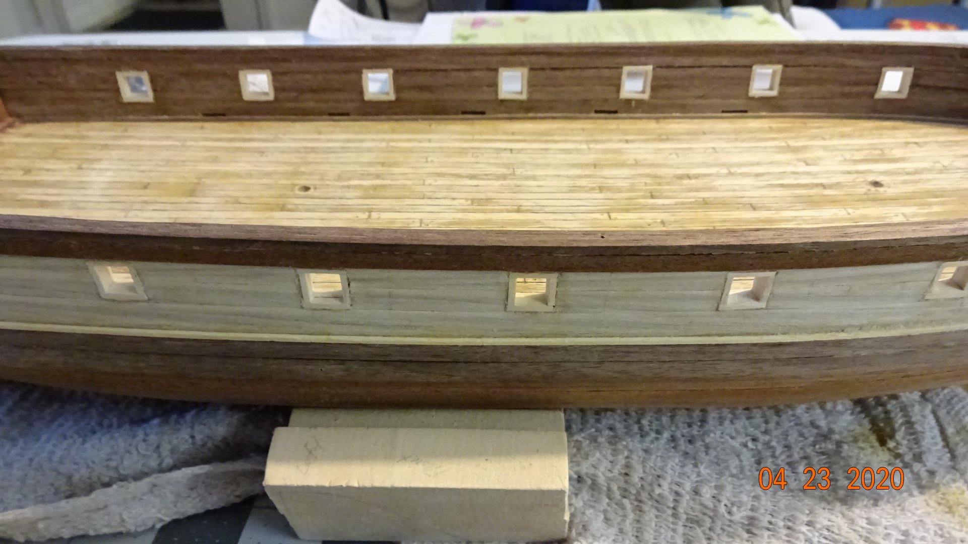
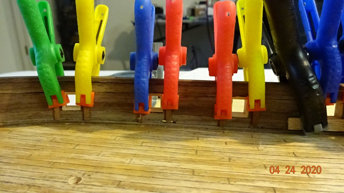
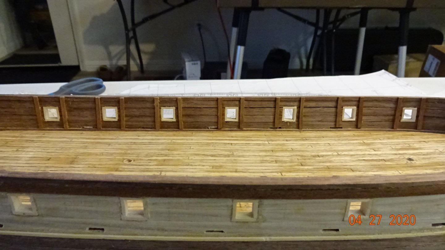
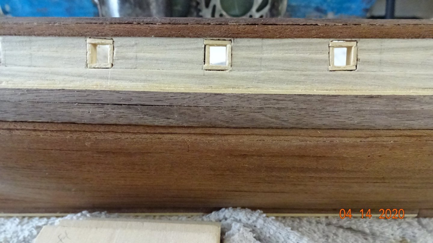
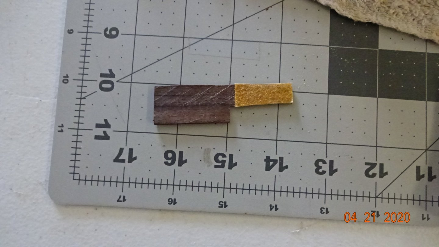
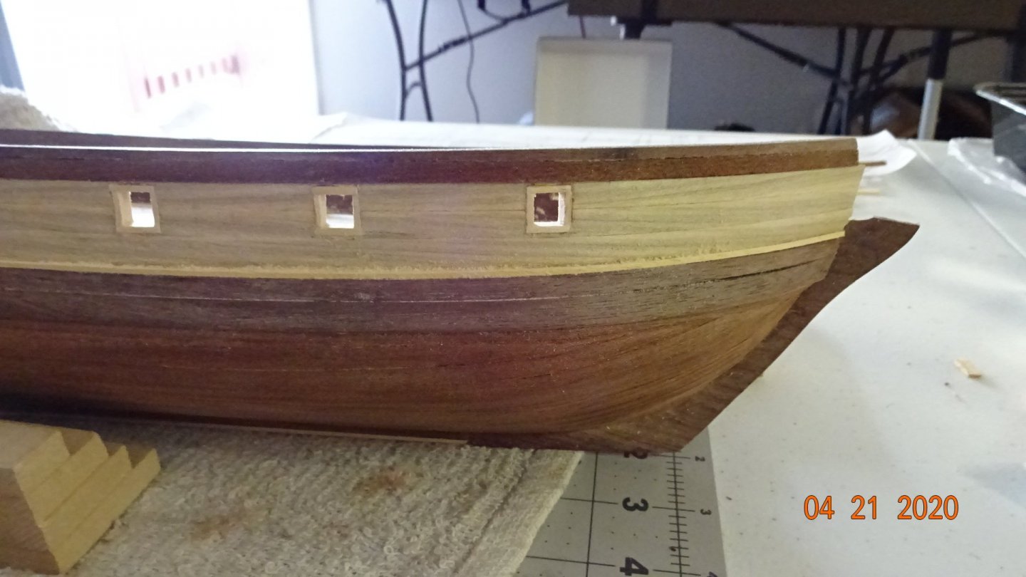
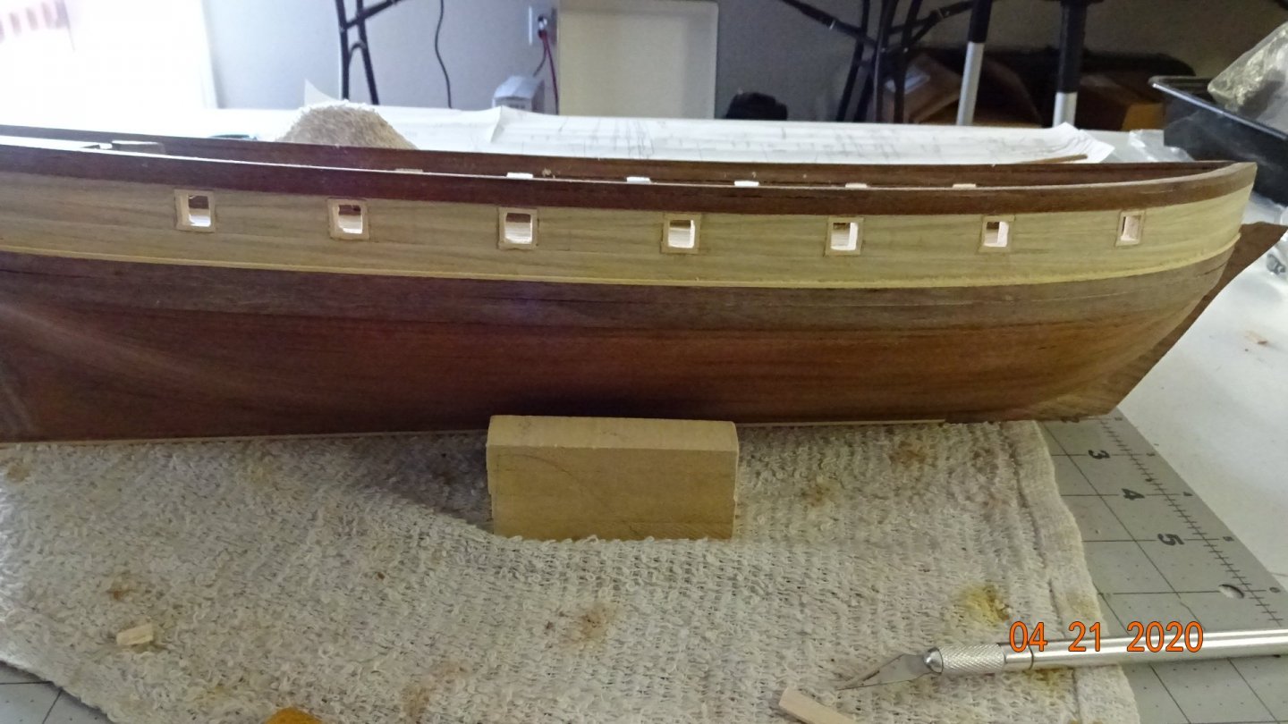
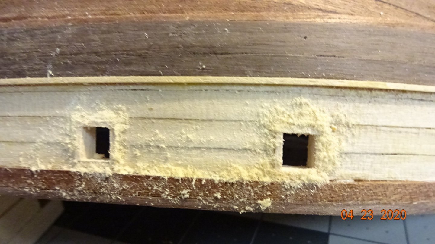
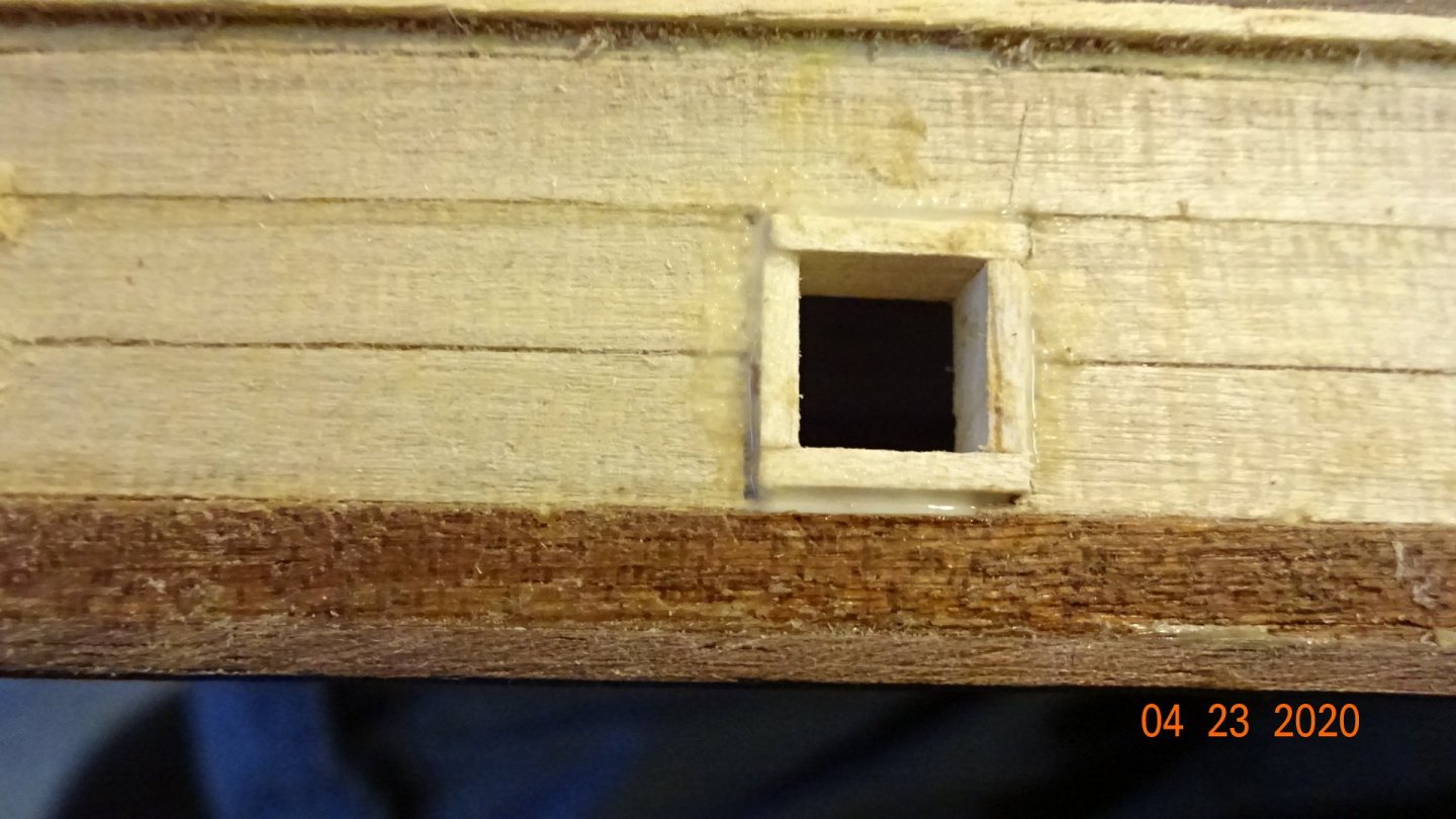
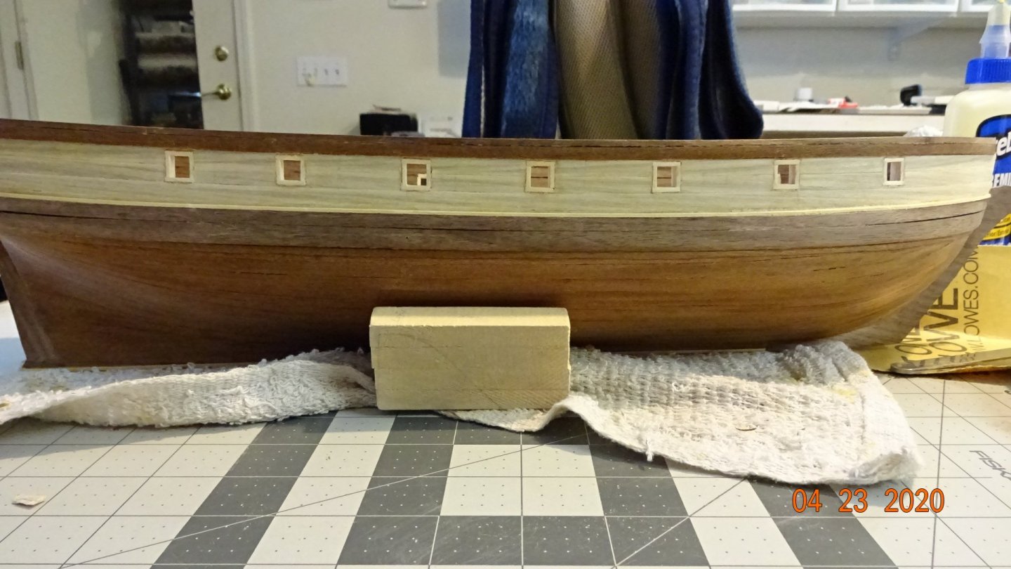
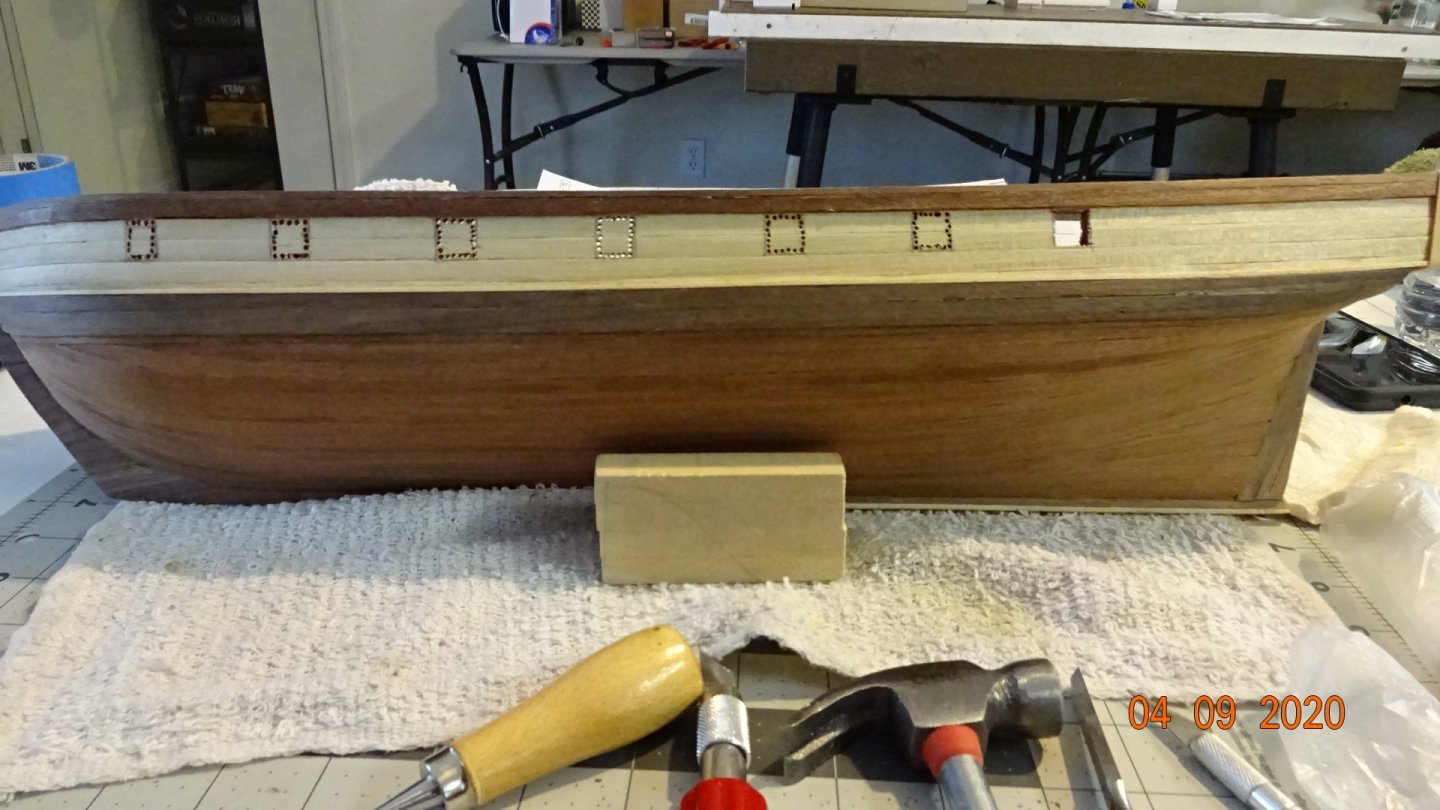
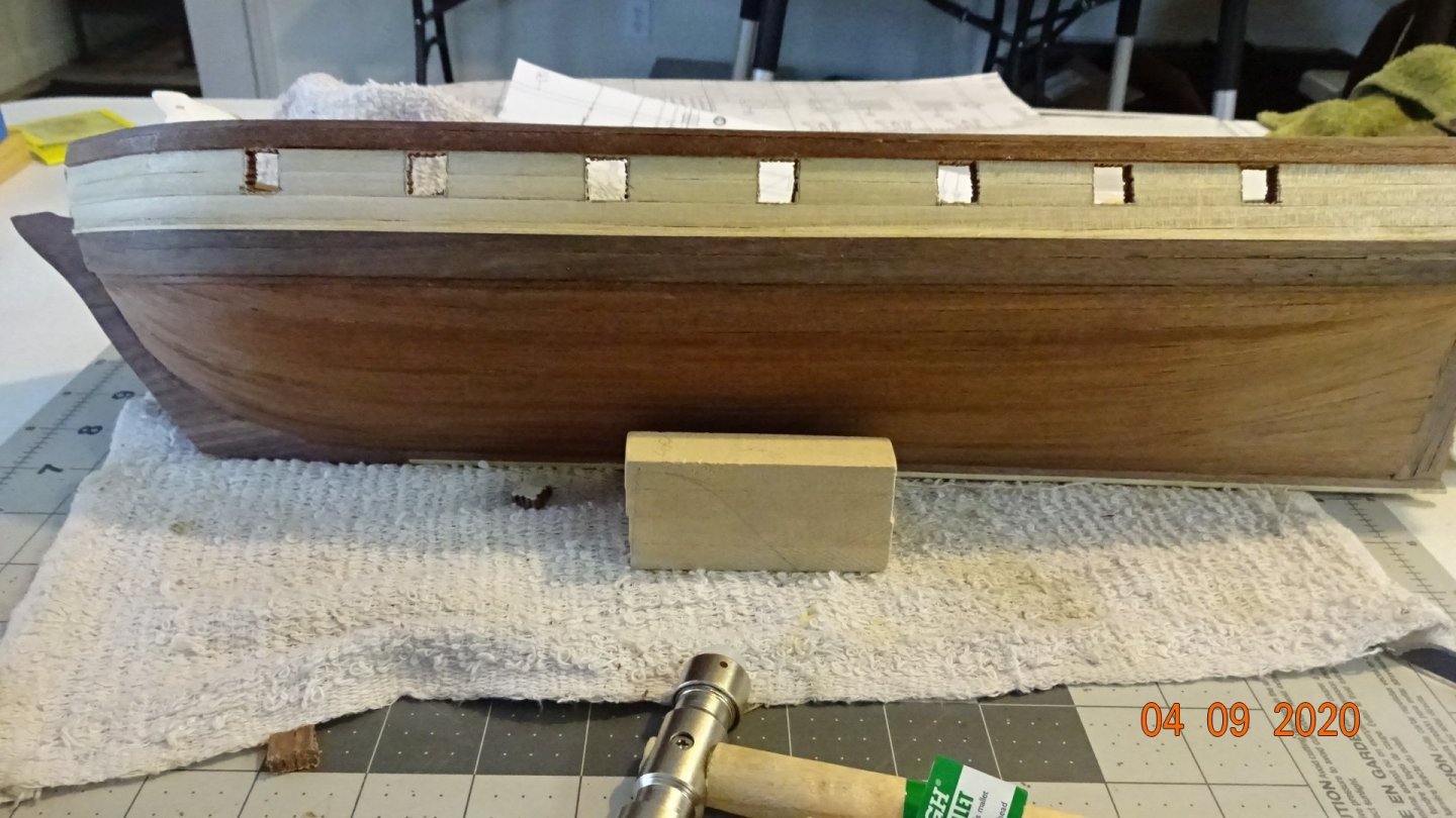
Started cutting the port frames and installing. Did not like what I was seeing .... Those squares were horribly out of square. Took another modelers suggestion of gluing some sand paper to a square surface. Here's my tool, functional but not pretty. The width is just enough to fit into the cannon ports. Spent some time with the new tool, knife, and small metal file squaring the ports. I am happy with the results. A close up picture reveals some flaws still. Here's the solution I used to fill in the gaps. Again, this idea is from another modeler. Sanded down a plank I used for making the frames. Make mix of glue with some water. Applied liberally around the ports. First the glue and then added the sandings. Pressed the sandings into the holes as best as possible. Then sanded with 100 grit sand paper. Perfect, no way, but much better than my initial looking ports. In case you forgot what they started like, here's the picture again. I may add another round of sandings to the ports but overall they look much better to me, and that's what counts


- 195 replies
-
- 4
-
-
- enterprise
- constructo
- (and 1 more)
-
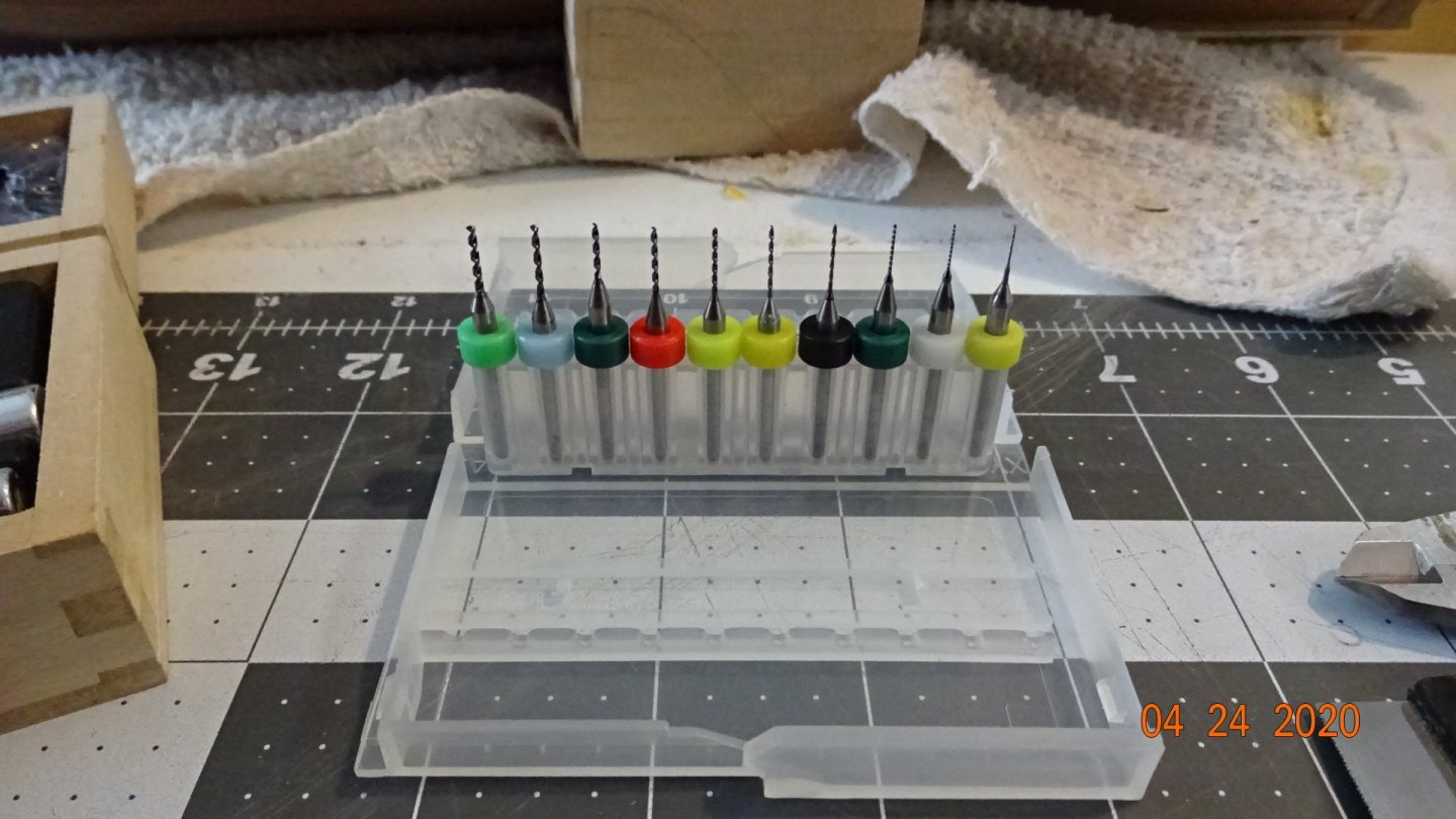
Drilled the holes out for the cannon ports. Started with an 1/8th inch steel bit but it started smoking after awhile. Switched to some bits I picked up on Amazon, WaylinTop 50pcs PCB Drill Bits. Did a great job of drilling through the wood, did break one but there are 5 bits for each of different sizes. Also started cutting out the port "squares", using a small chisel and knife.

- 195 replies
-
- 3
-
-
- enterprise
- constructo
- (and 1 more)
-
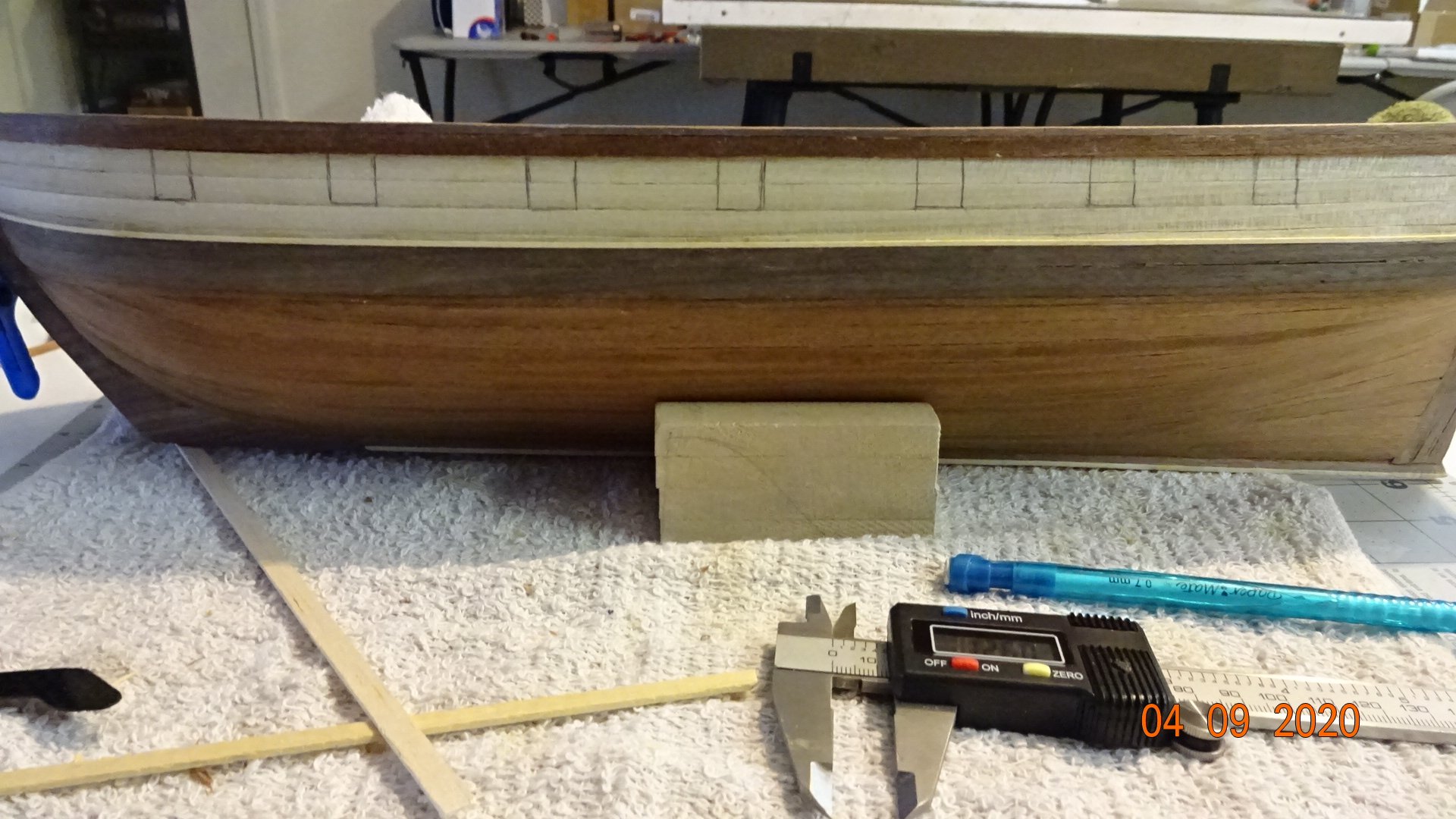
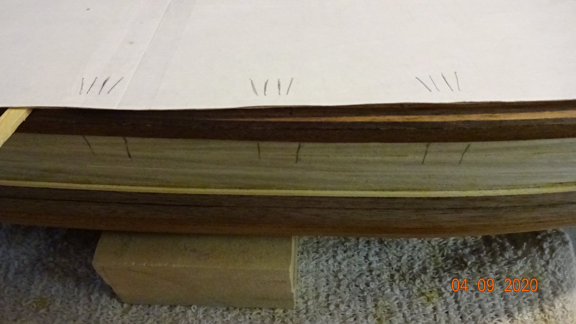
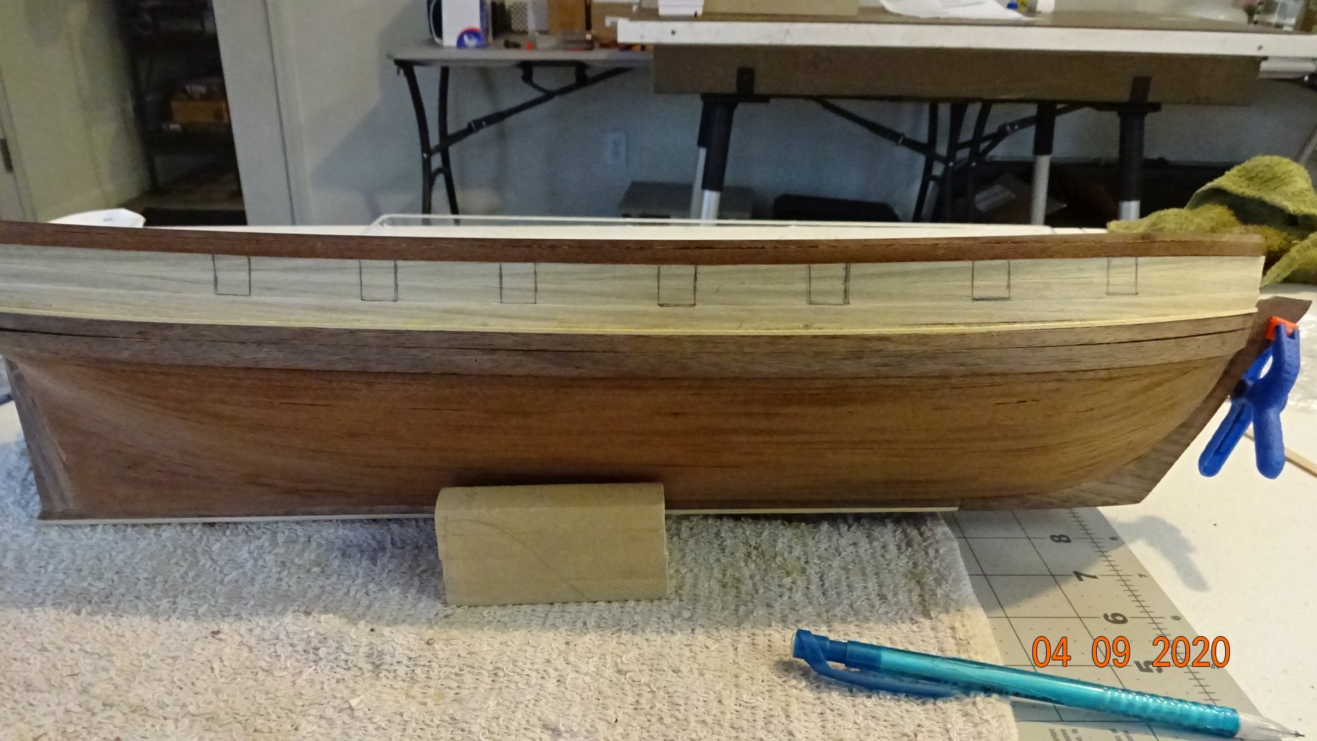
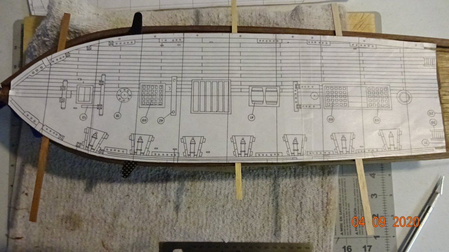
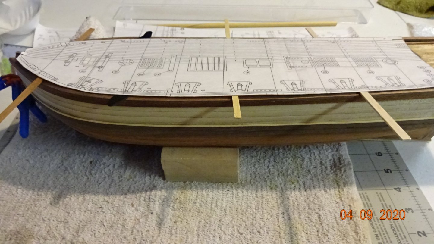
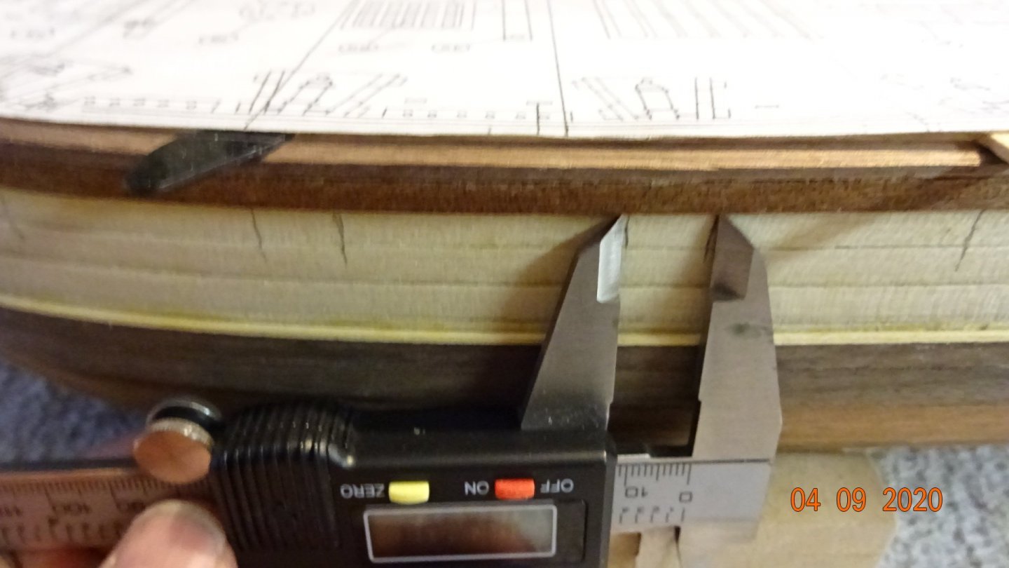
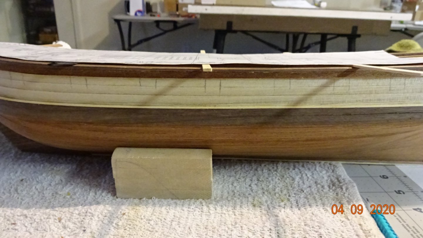
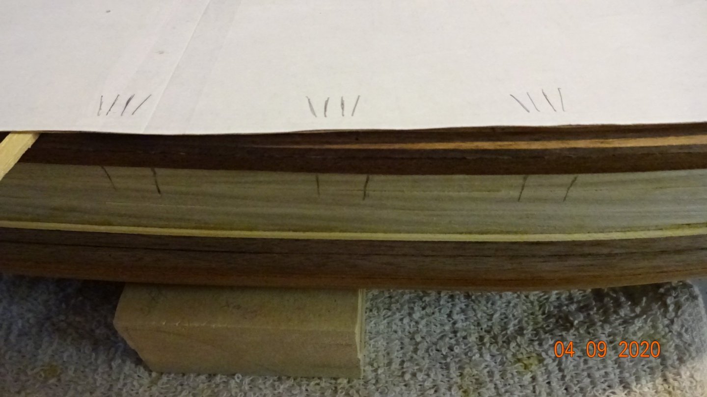
Next, on to the cannon ports. I kept it simple. Used a cutout of from the plans of the deck. Supported it with extra planks. Take a look. Then I used a caliper to mark the locations of the cannon ports. Port side cannon ports marked. Using the calipers I measured the length of the ports , marked and completed the cannon port drawings. Ready for cutting out. Followed the same process for the starboard side, I did have to turn the deck cutout over and make some marking as reference points. Overall the process went smoothly, though I did break off the top of my stem Next post will be the cutting out of the ports.


- 195 replies
-
- 4
-
-
- enterprise
- constructo
- (and 1 more)
-
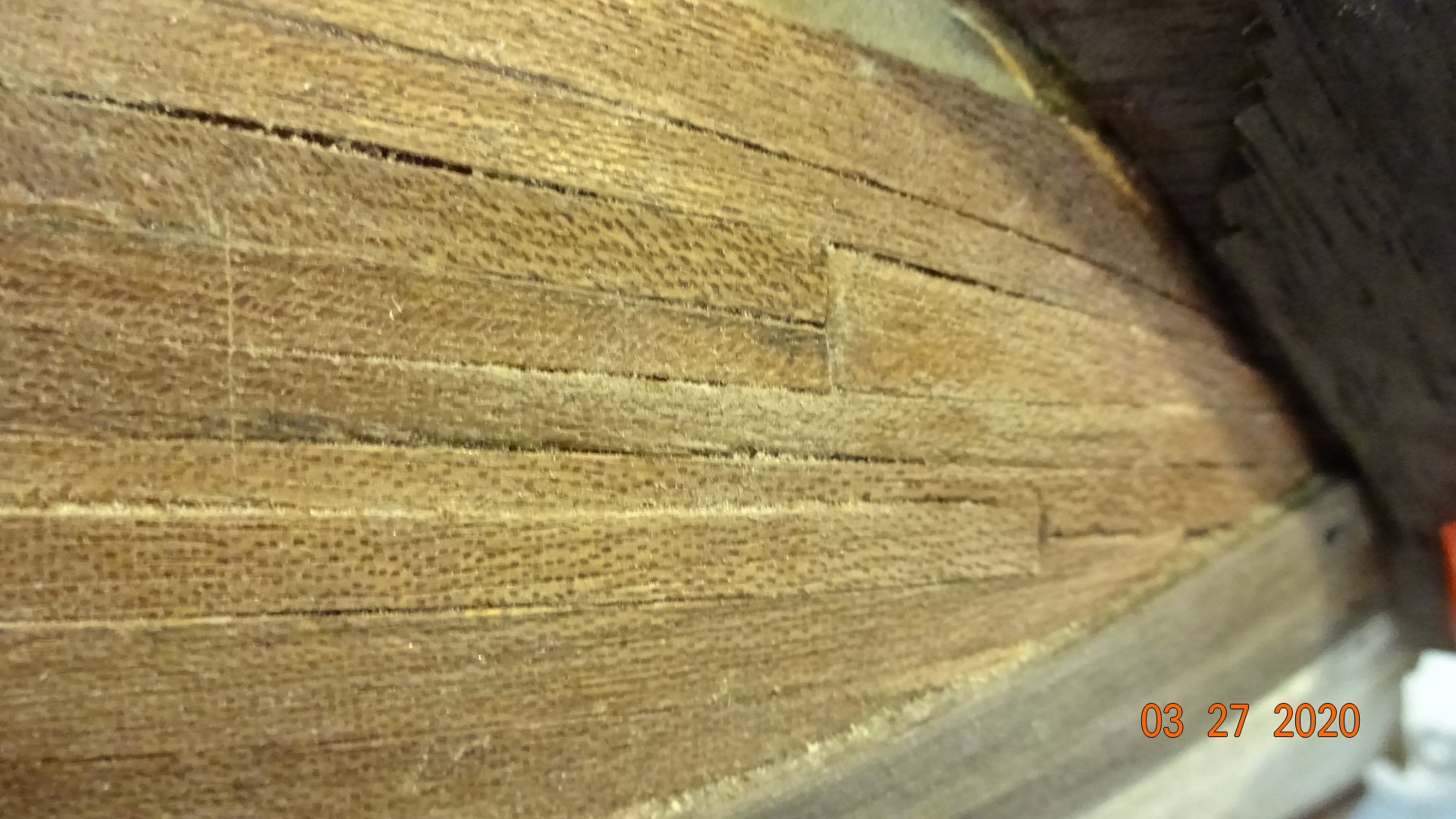
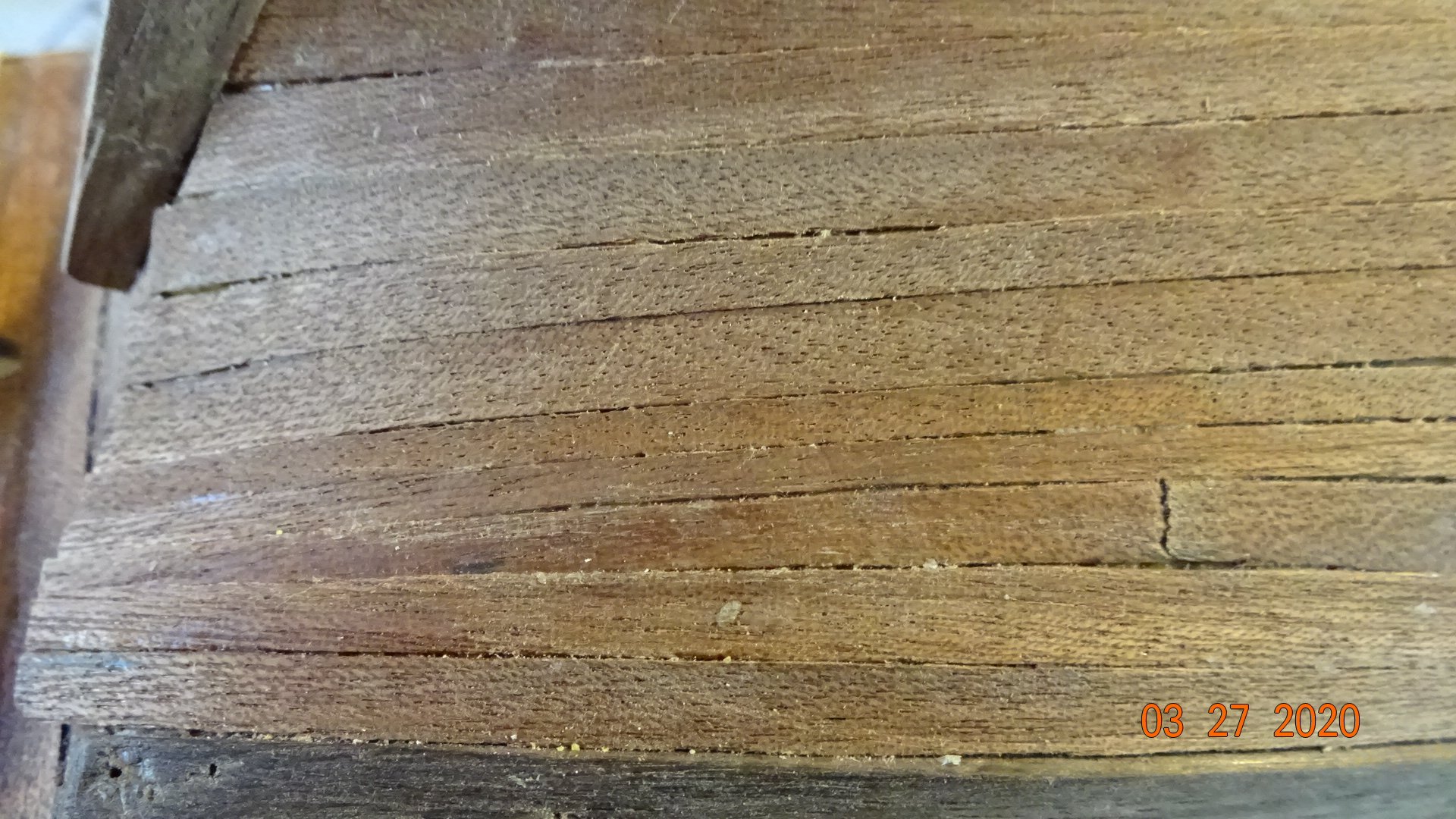
@SIDEWAYS SAM First, Wow what a great example of planking ! And that's a close up picture. Mine is not close to that, maybe if viewed from a distance, lol. I'll be spending more time on trimming, beveling and fitting trying to attain that level of accurateness. Thanks for the info and pic.
-
I have a question. Does the 2nd planking get "wood filler" put on it? Is it normal to have to put filler on the 2nd planking or do I just need to do a better job? The gaps on the 2nd planking are minimal but there are some. Thanks for any input.
- 195 replies
-
- 1
-
-
- enterprise
- constructo
- (and 1 more)
-
I see a few of the pictures I posted actually double posted. not sure what’s going on but sorry for extra images.
-
@captain chaos yes, I purchased the mini table saw and mini planer. definitely glad I did as this kit is missing lots of lumber. later when I decide to do a scratch build I’ll be ready😀. thanks everyone for their input.
- 195 replies
-
- 1
-
-
- enterprise
- constructo
- (and 1 more)
-
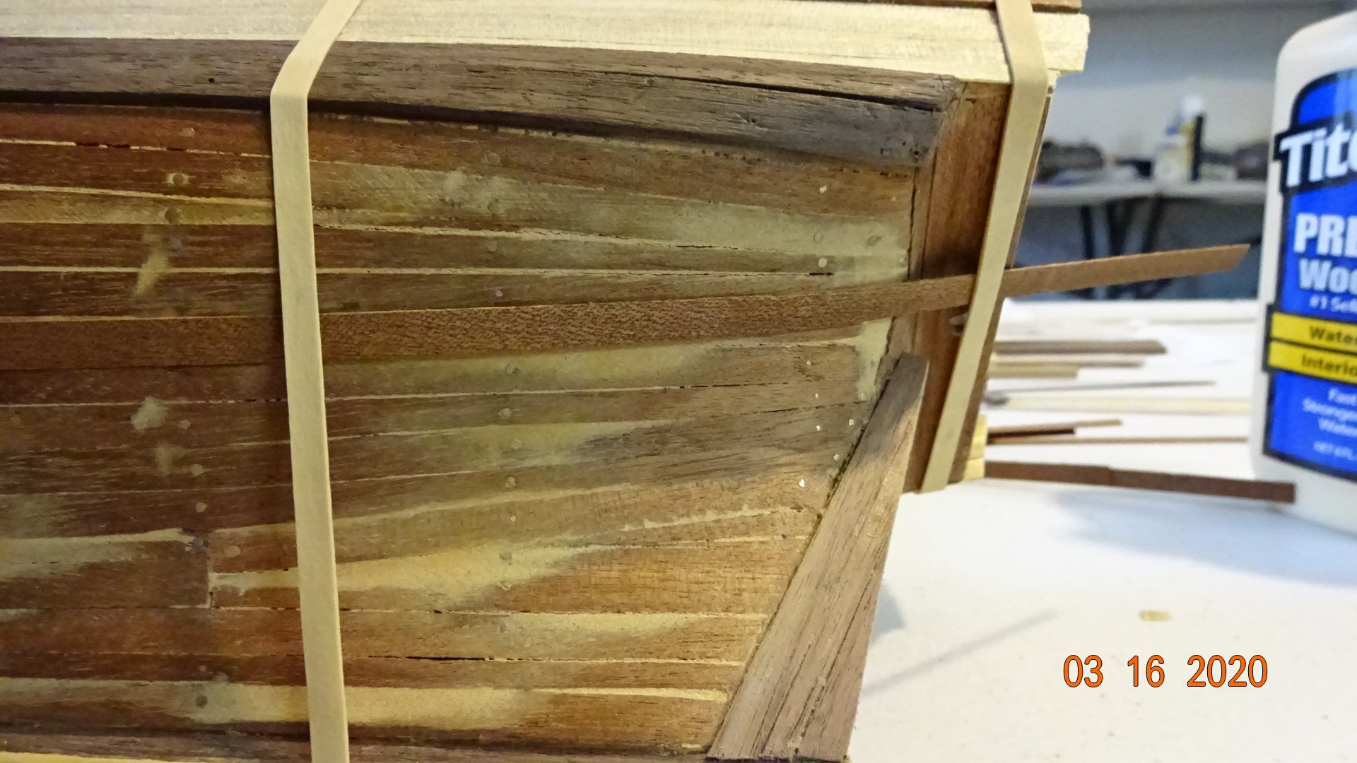
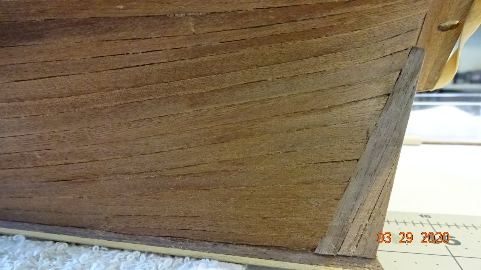
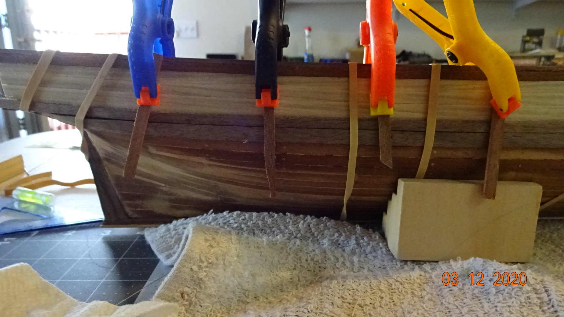
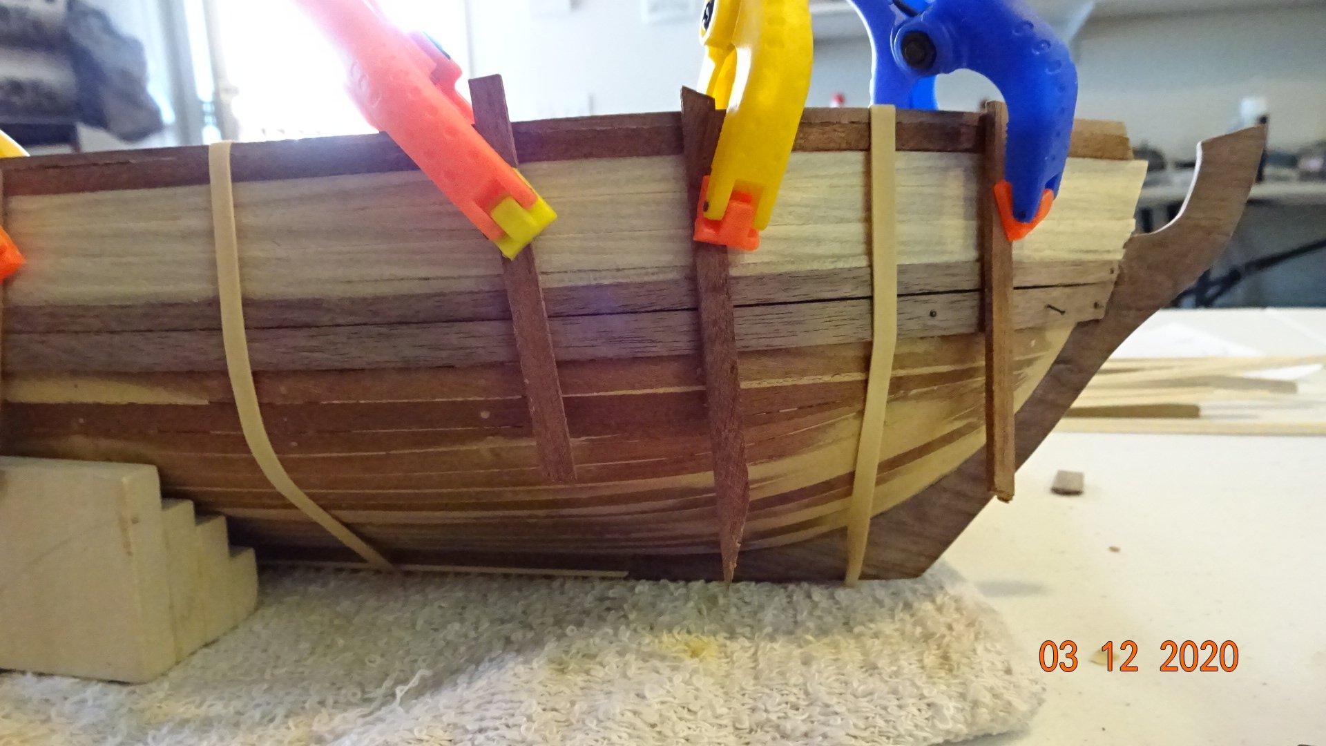
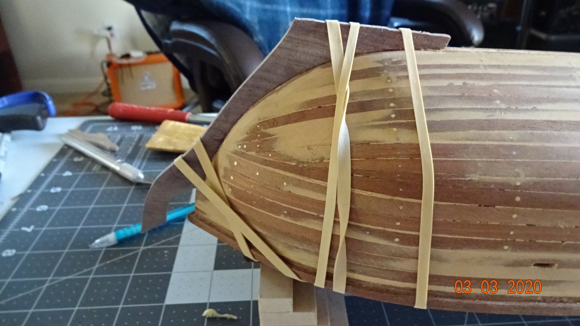
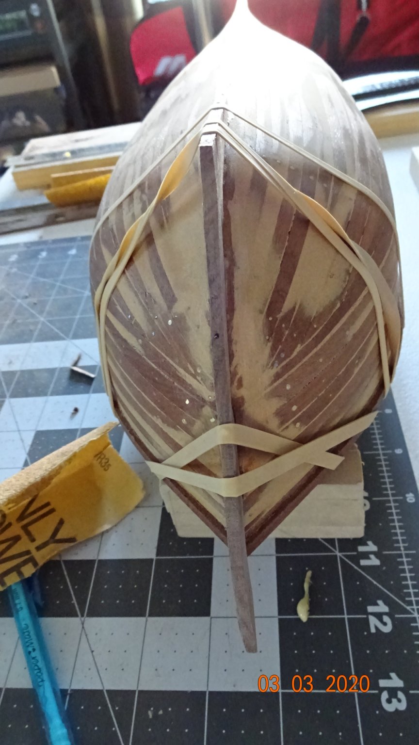
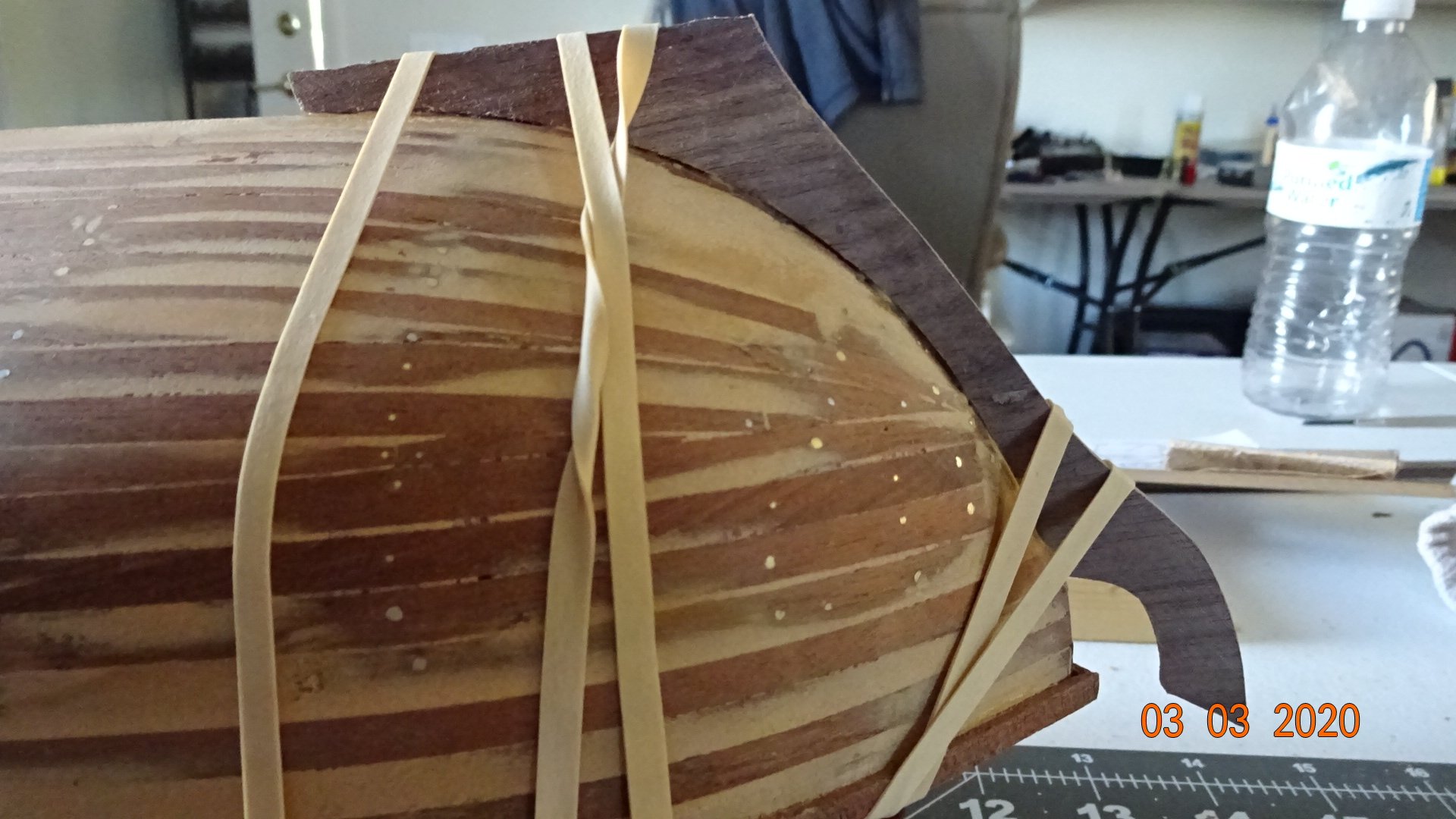
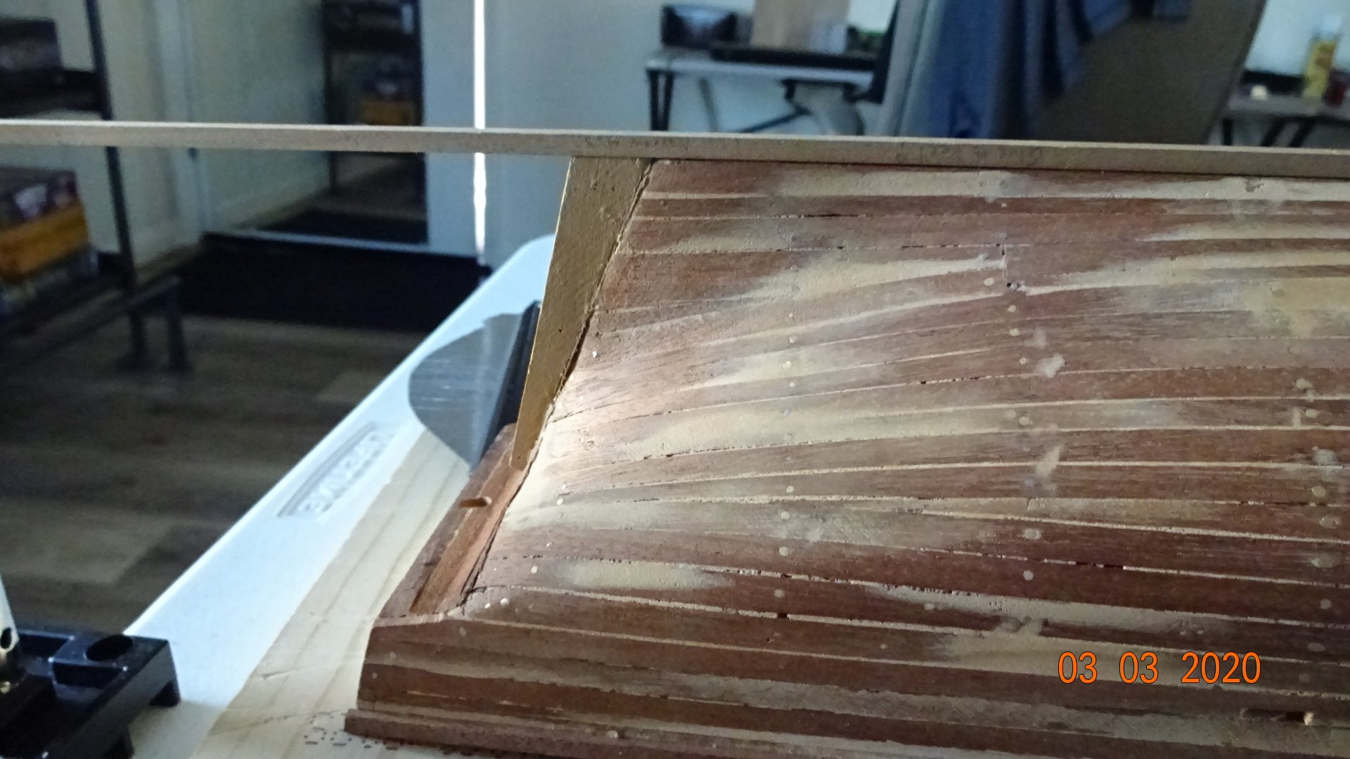
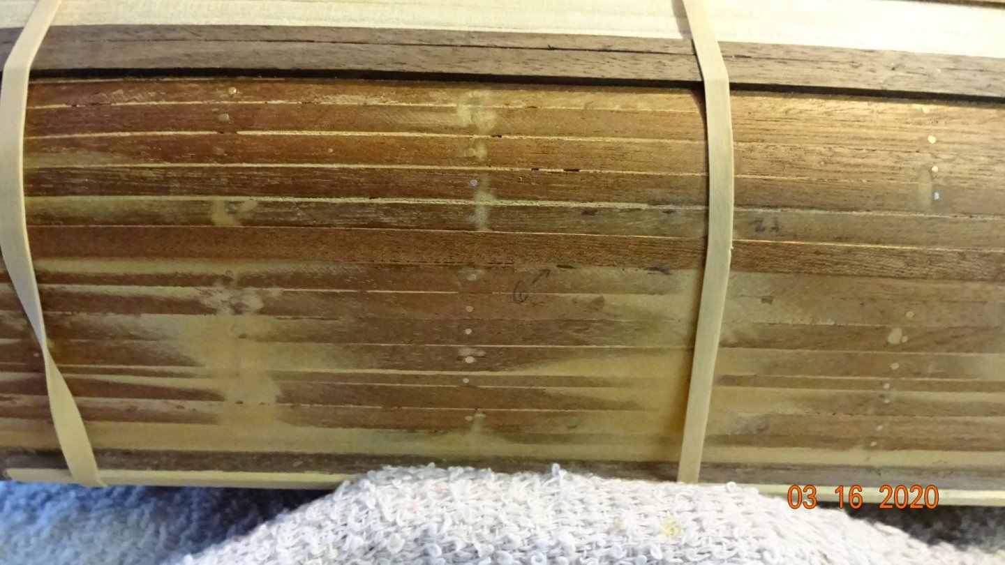
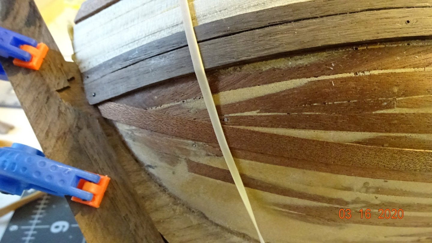
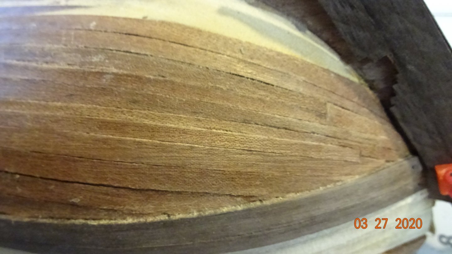
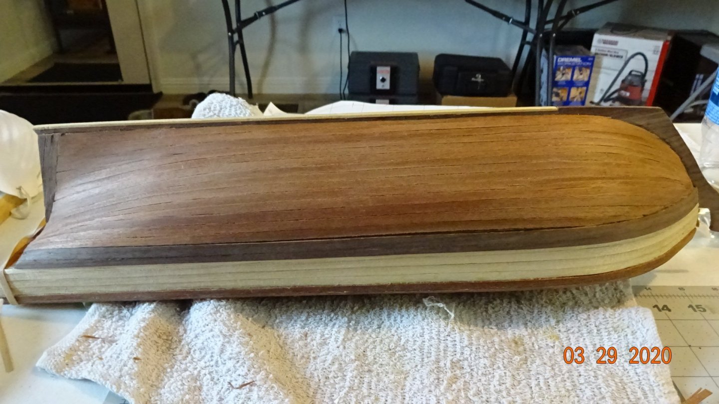
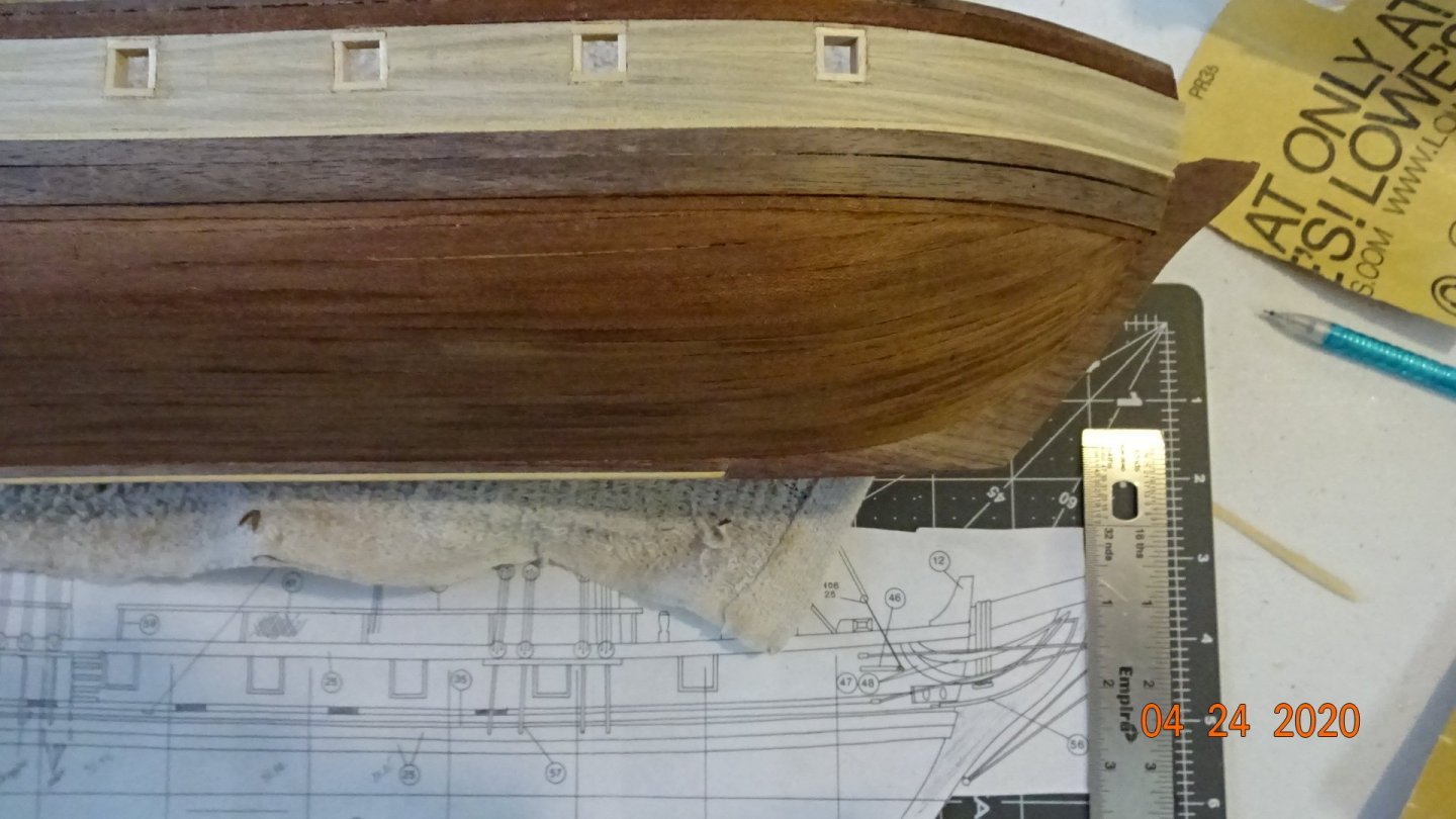
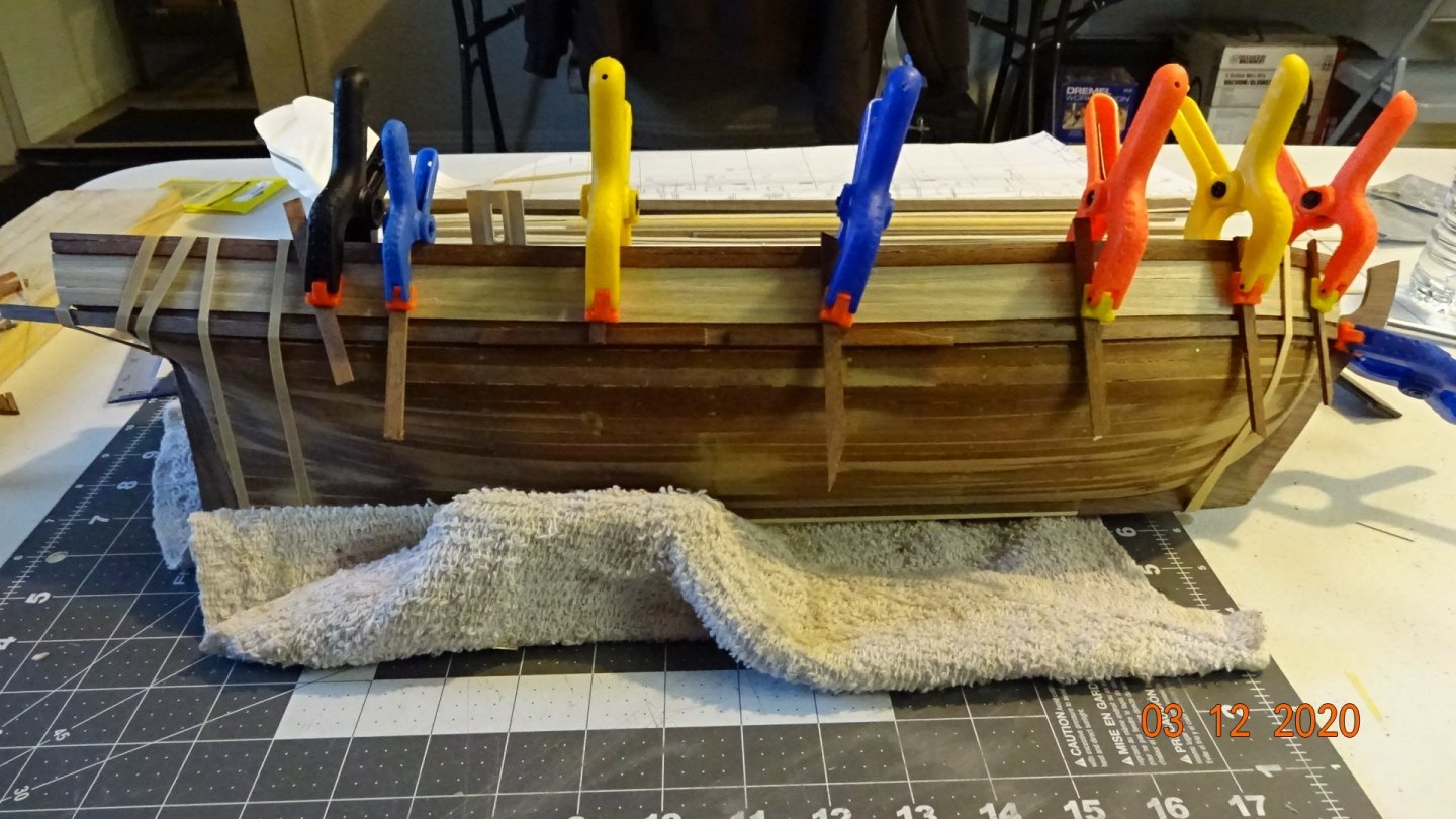
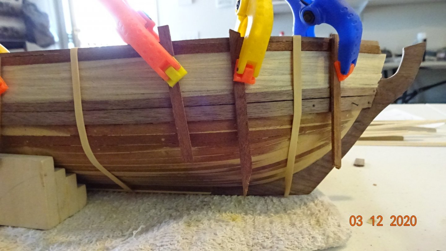
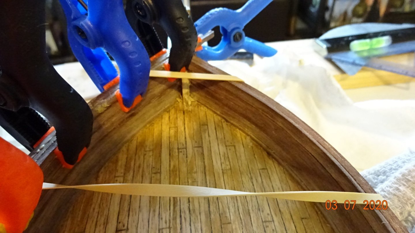
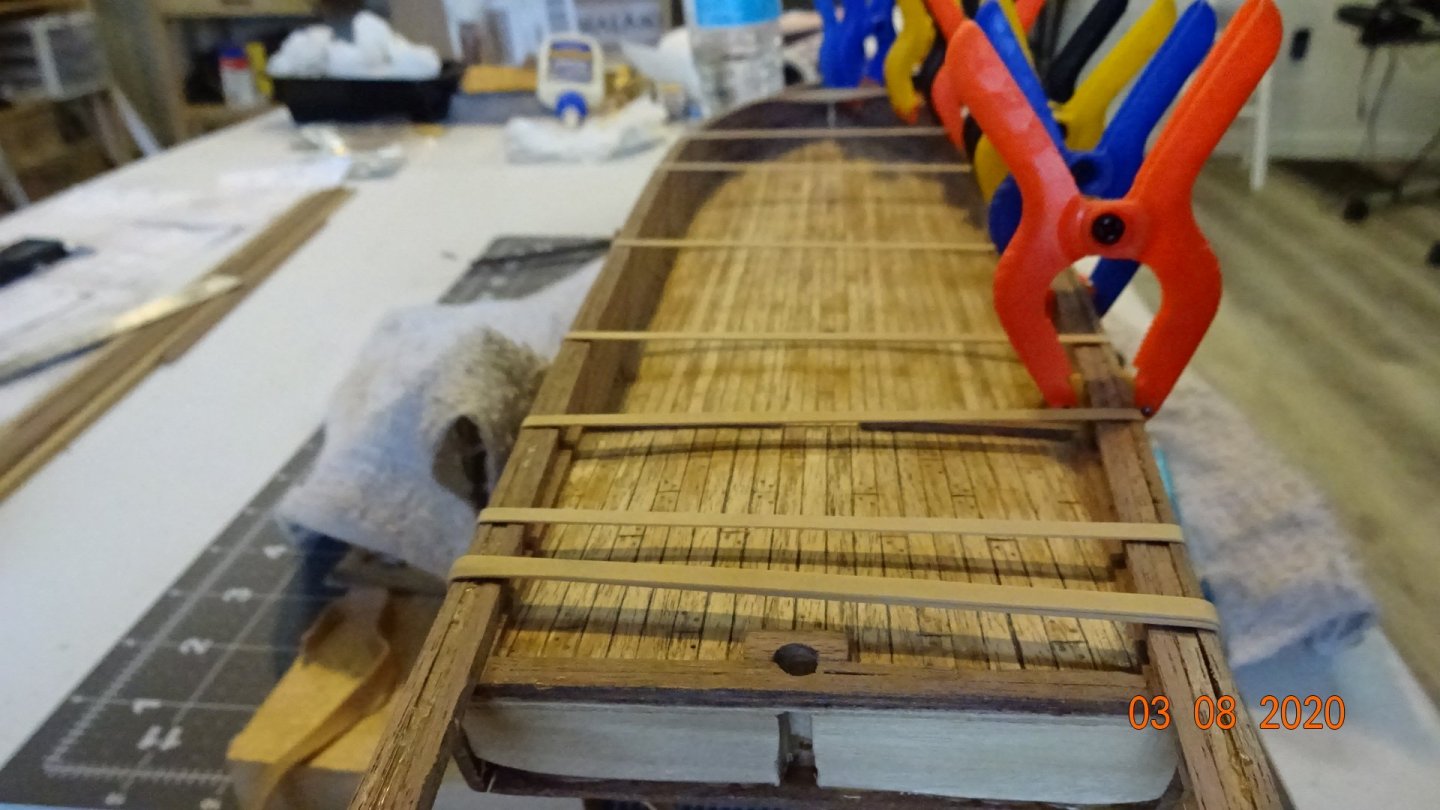
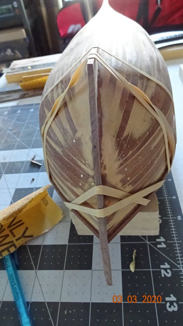
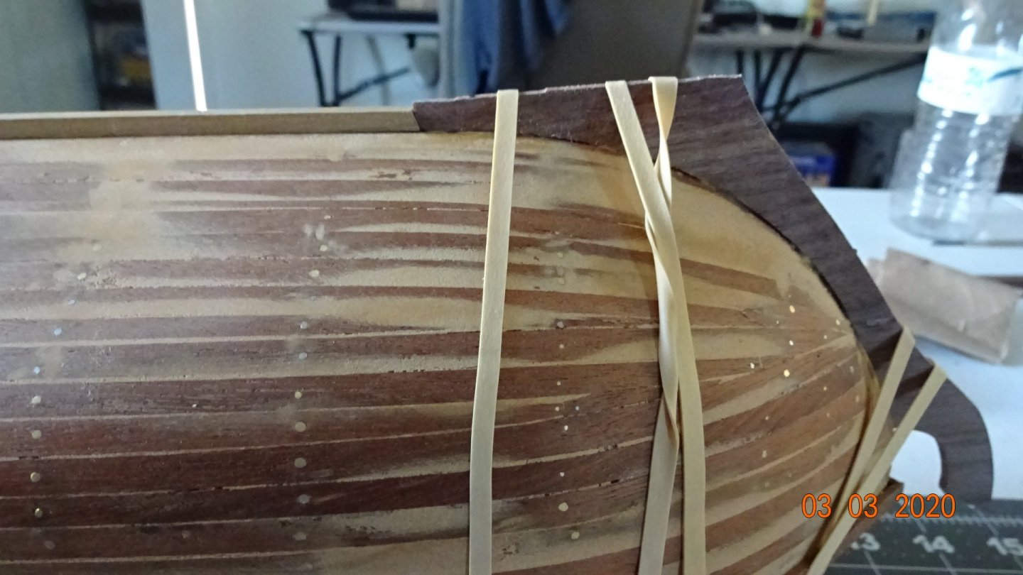
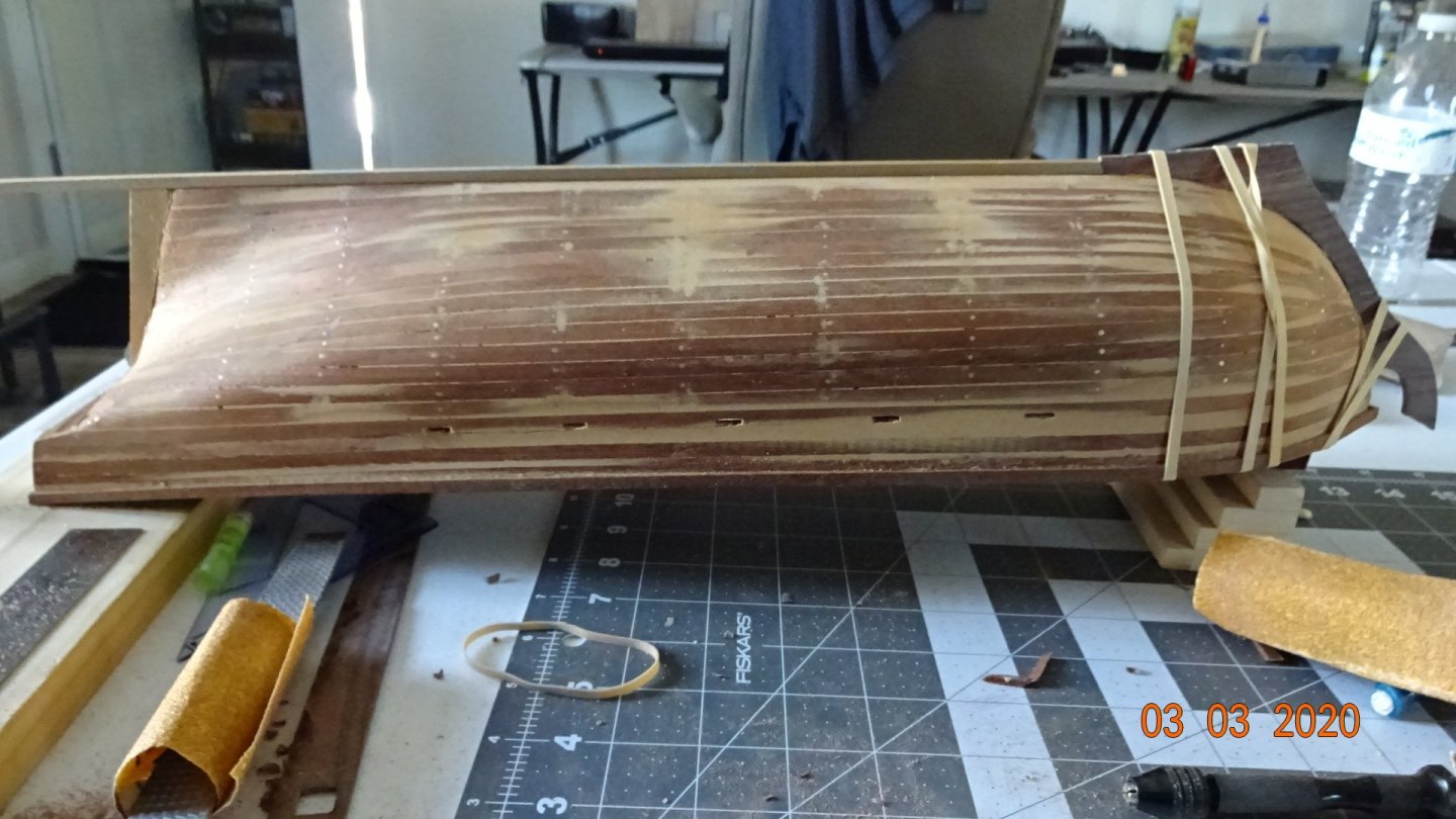
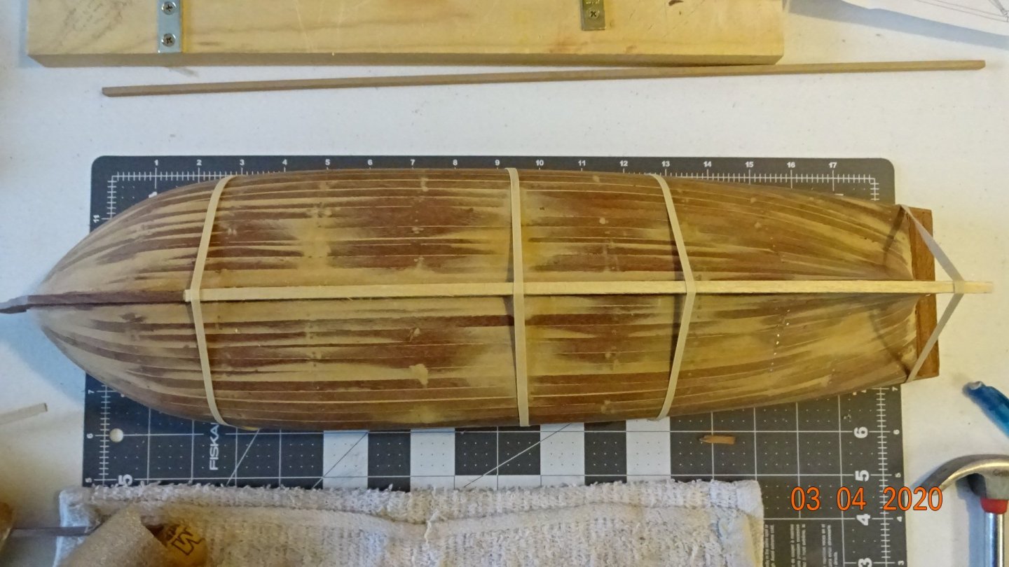
Somewhat intimidated with this section of the planking. Here goes.... First I measured down 6mm to where the first batten plank would go. I put on the planking and let it lie naturally. No upwards or sidewards bending. This did cause some concern at the bow area. I still have 5 more pieces of planking to add and there is no room at the bow ! Stearn area looks fine. The rubber bands help a little in holding the plank but mostly put glue on the hull and the plank then let dry a little. Starting at the bow I manually held the plank in place for a minute, then continued doing this every 4 or 5 inches . This worked since there was no strain on the plank as I initially just let the plank lay normally, no bending. If I had tried to manipulate the plank (bend), I doubt I would just be able to hold it in place for a minute to have it set. Here's progress on the 2nd planking. At the bow I just ran the planks into the lower wale. I ended up having some whole planks (short pieces but still 4mm wide) at the bow merge with two half planks (each 2mm wide). One can also see that I did some half cuts on the planks near the bow lower wale. Probably should have marked this up in a picture editor but I'm ready to keep moving forward on this. The stern area came out nice. One piece did crack, as is seen in the pic below. But nothing some glue can't fix. Since I had that first batten plank lay naturally it made it easier for the next planks. Normal trimming at the bow but other wise set and glue. Finally the finishing pieces... The bow continued needing trimming while the stern required "steelers" to be cut. I think they are called steelers? A triangle shaped piece that fits between two planks at the stern. Here's a look at the entire model with the port side 2nd planking. A little work still needed near the lower wale and of course lots of sanding. I'm not sure if the way I laid the lower wales is correct or not. Should they have been curved up at the bow area more? .... added the plan pictures of the wales and there is a slight upward taper. I think I ended in the right place just below the top of the stem. Mark this as another learning point . Feel free to input on any of my posts, good or bad. That's it for now.


- 195 replies
-
- 5
-
-
- enterprise
- constructo
- (and 1 more)
-
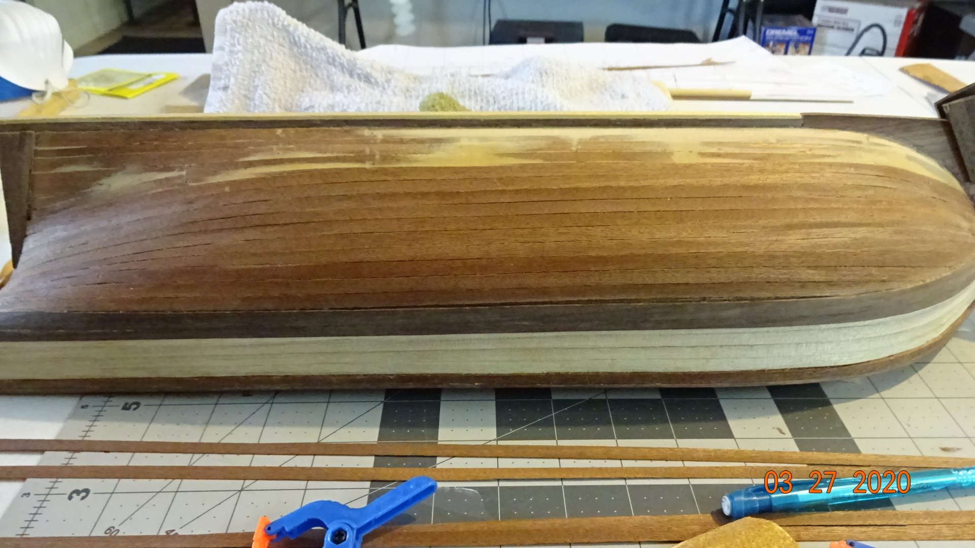
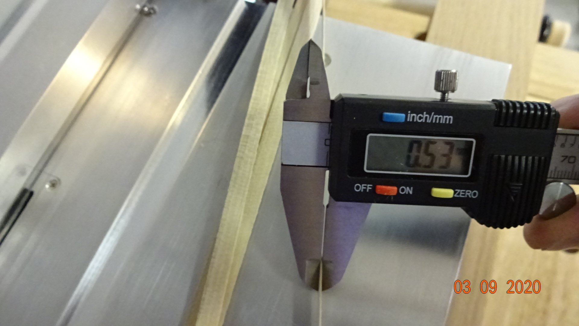
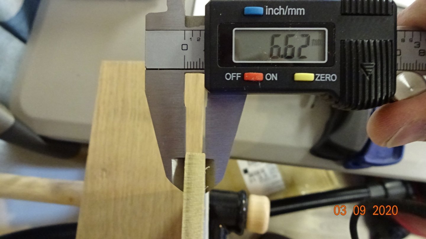
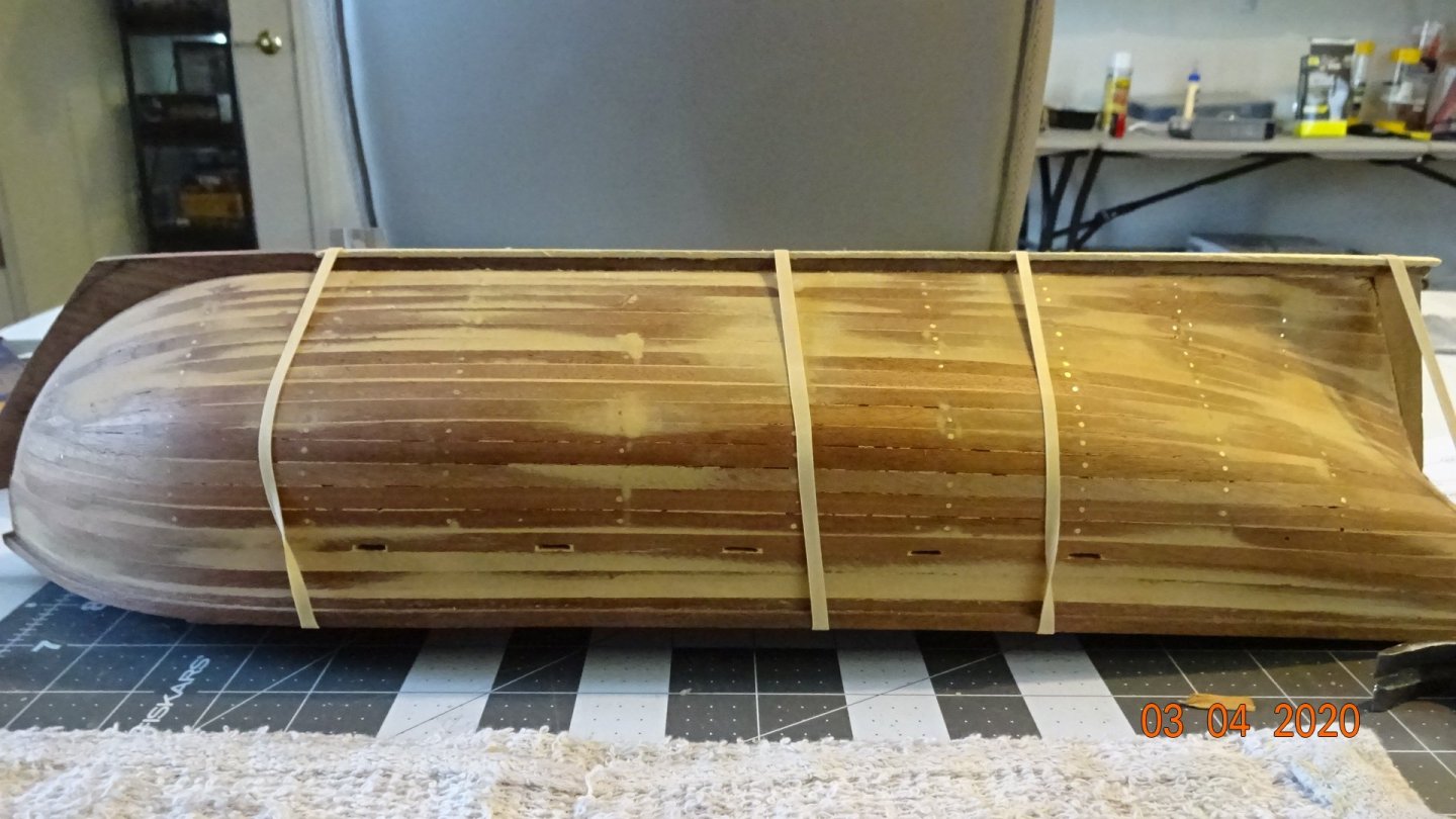
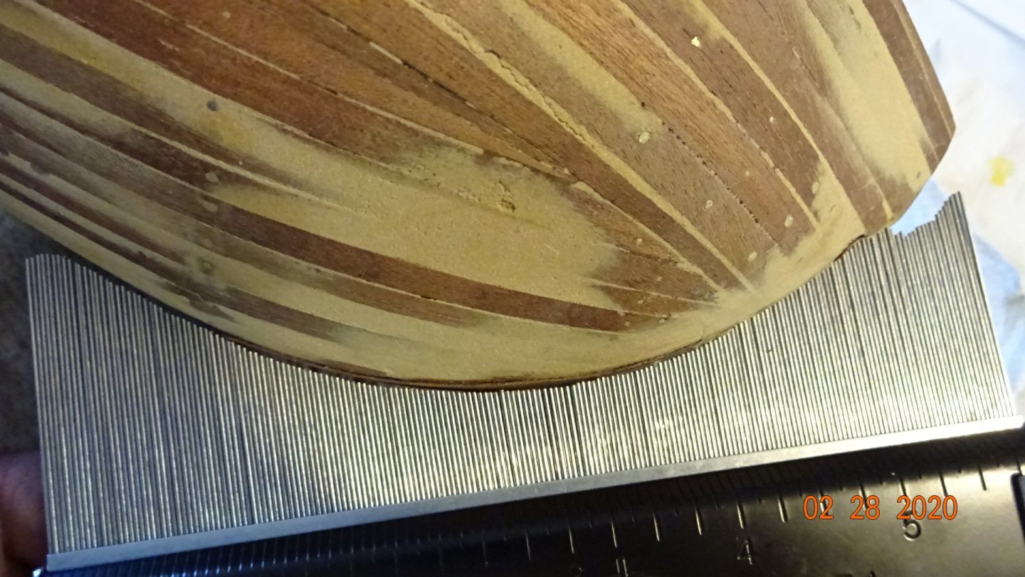
Today I start milling the popular wood that will be used for the 2nd planking. Picked up a piece at Home Depot, a little over 6mm. Ripped some boards length ways and milled them down to about .5mm. That's the thickness of the 2nd planking. Measured , cut and glued the starboard side planks. Here I'm setting the first of the lower wales. I used the blueprints to determine where the wales should lie. (Note to self: take a picture of the blue print and post). I had not completed the lower wales, still needed 1 more piece. Oops, forgot to protect the Stem 😧 The manual also had and upper wale. What's the verdict sea goers, does the popular wood look okay? Next post will be on planking the section below the wales.


- 195 replies
-
- 4
-
-
- enterprise
- constructo
- (and 1 more)
-
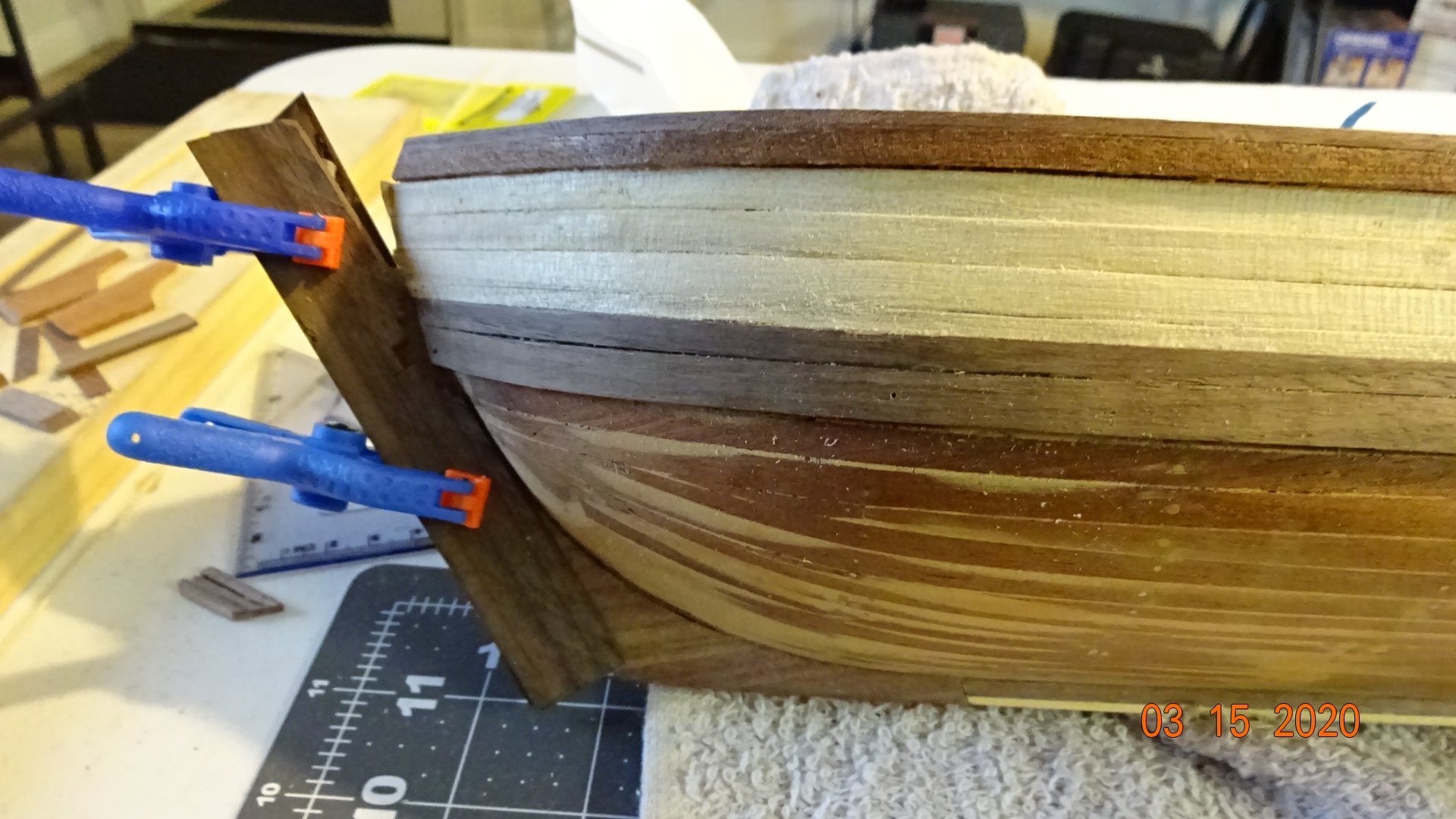
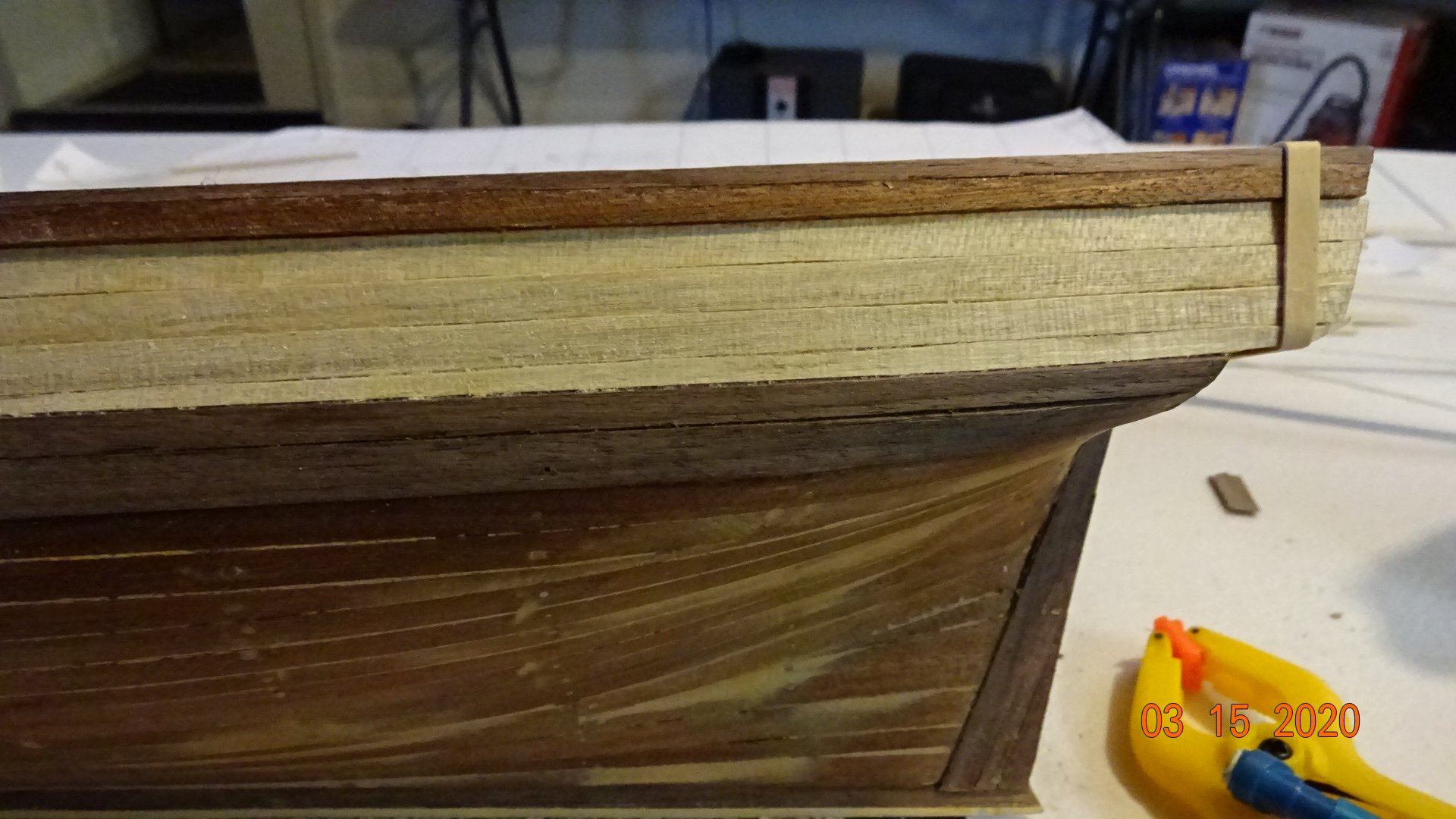
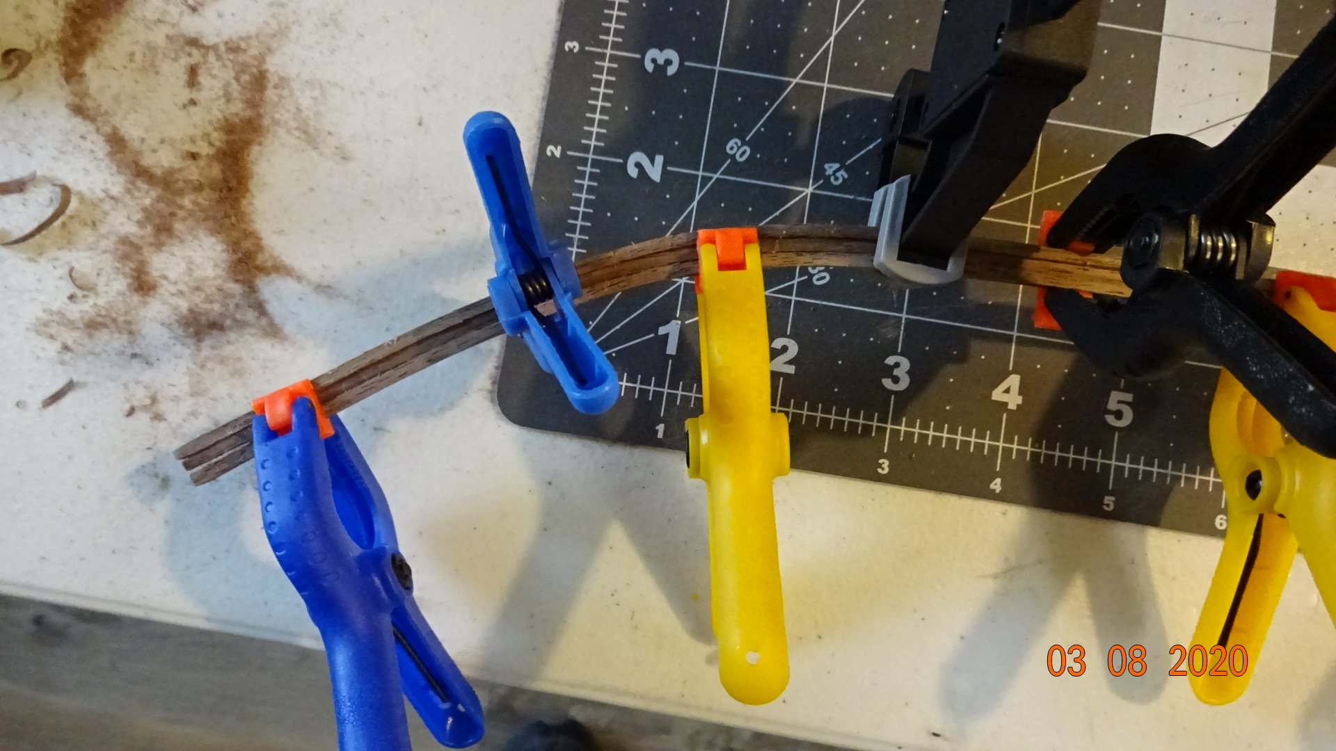
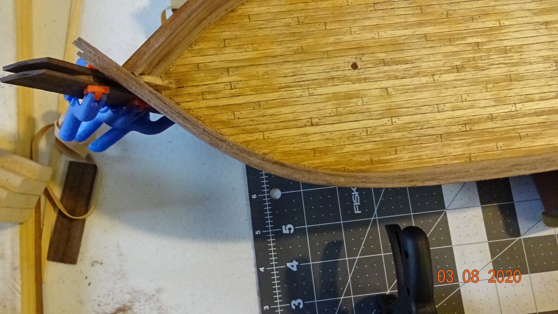
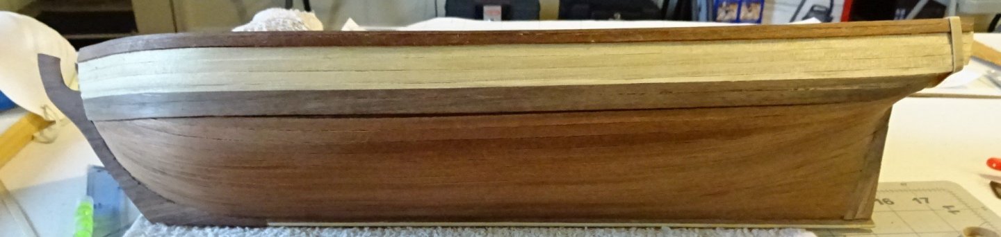
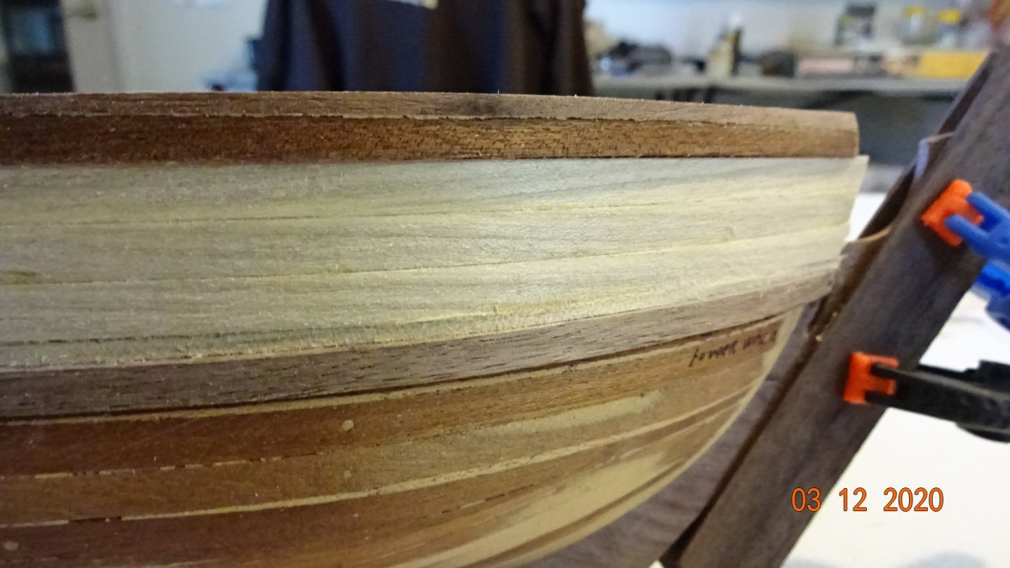
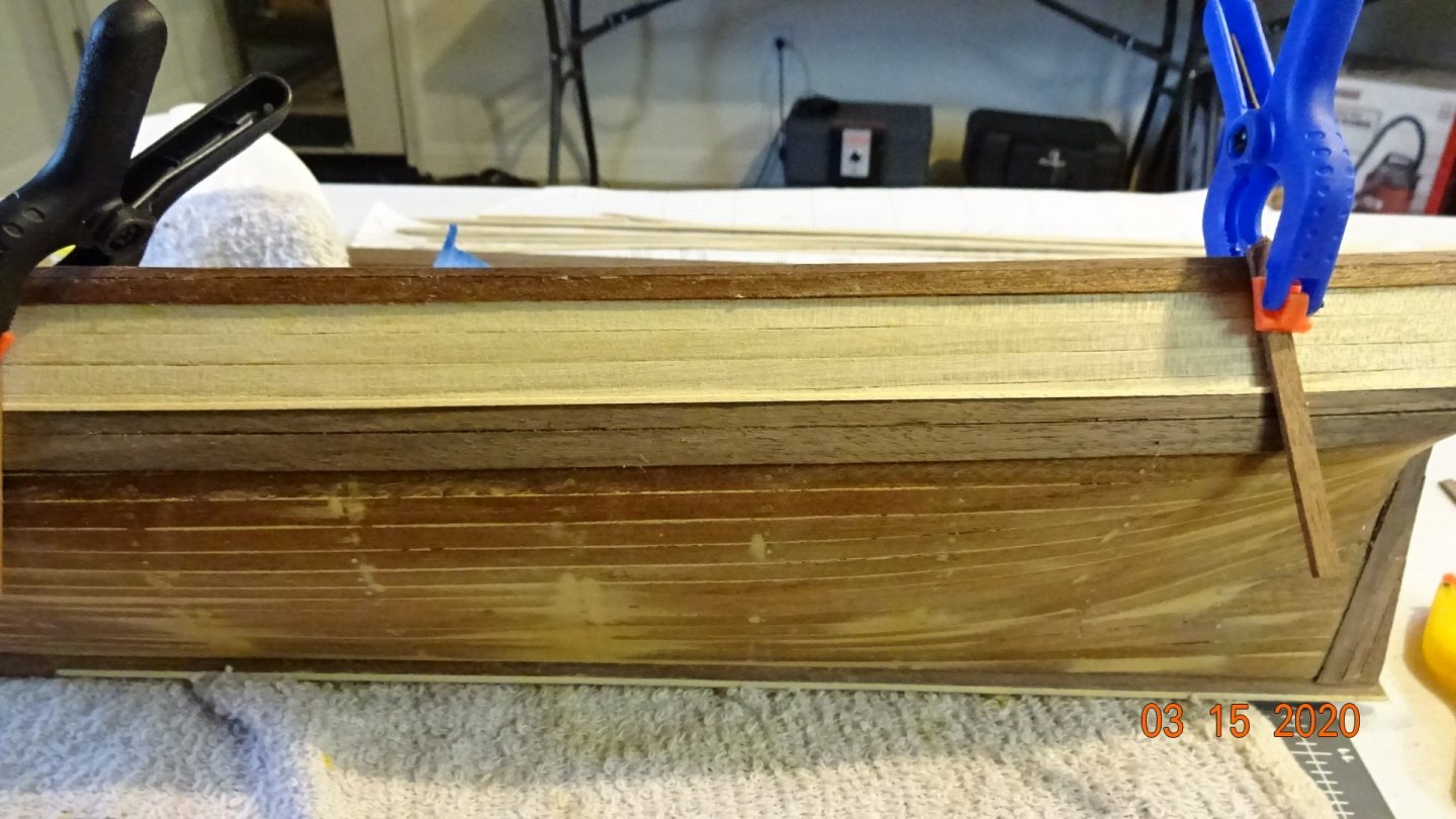
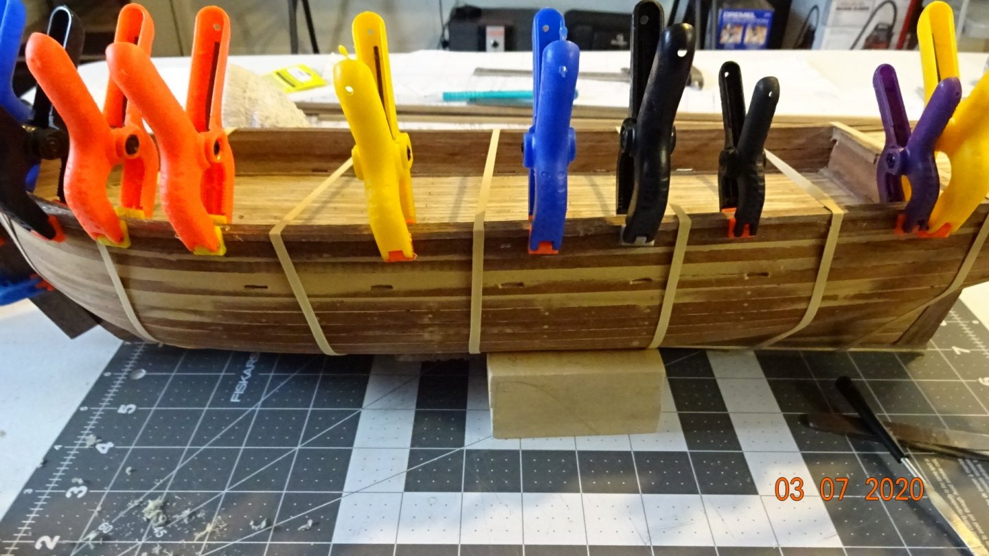
Back for some updates. The solution to my shortage of 2nd planking is to do a 2 tone hull. The part above the lower wales will be popular wood and the lower section will remain sepelli wood. First though, finishing the Stem , Keel, and rudder sections. Then onto the top rail. Here the instruction called for 3 pieces of wood be laminated together and then glued on the top of the hull planks. One for the port and one for the starboard sides. Each piece is 2mm wide by 2mm high, I used my jig to set the bend in each one separately. Then glued the 3 pieces together . Here's more pics of the work. Notice how I'm trying to protect the Stem. Don't want another break in that thing.😃 I'm posting this now before the computer or internet goes down.


- 195 replies
-
- 4
-
-
- enterprise
- constructo
- (and 1 more)
-
@Captain Chaos Excellent idea and I had thought about doing just that after looking at where the break points were. I even drew the Stem on the wood but never got around to cutting it out. So I'm tempting fate 😟 and trying to be more aware of that Stem. If it breaks again I may have no choice but to follow your suggestion. Thanks for the input.
-
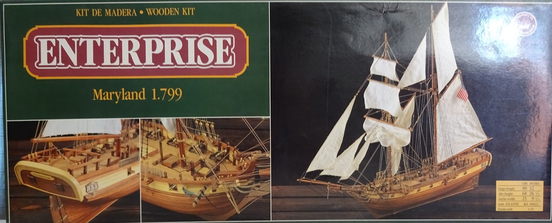
After looking at the model's box I realized the solution to my 2nd planking issue. 😀

- 195 replies
-
- 1
-
-
- enterprise
- constructo
- (and 1 more)
-
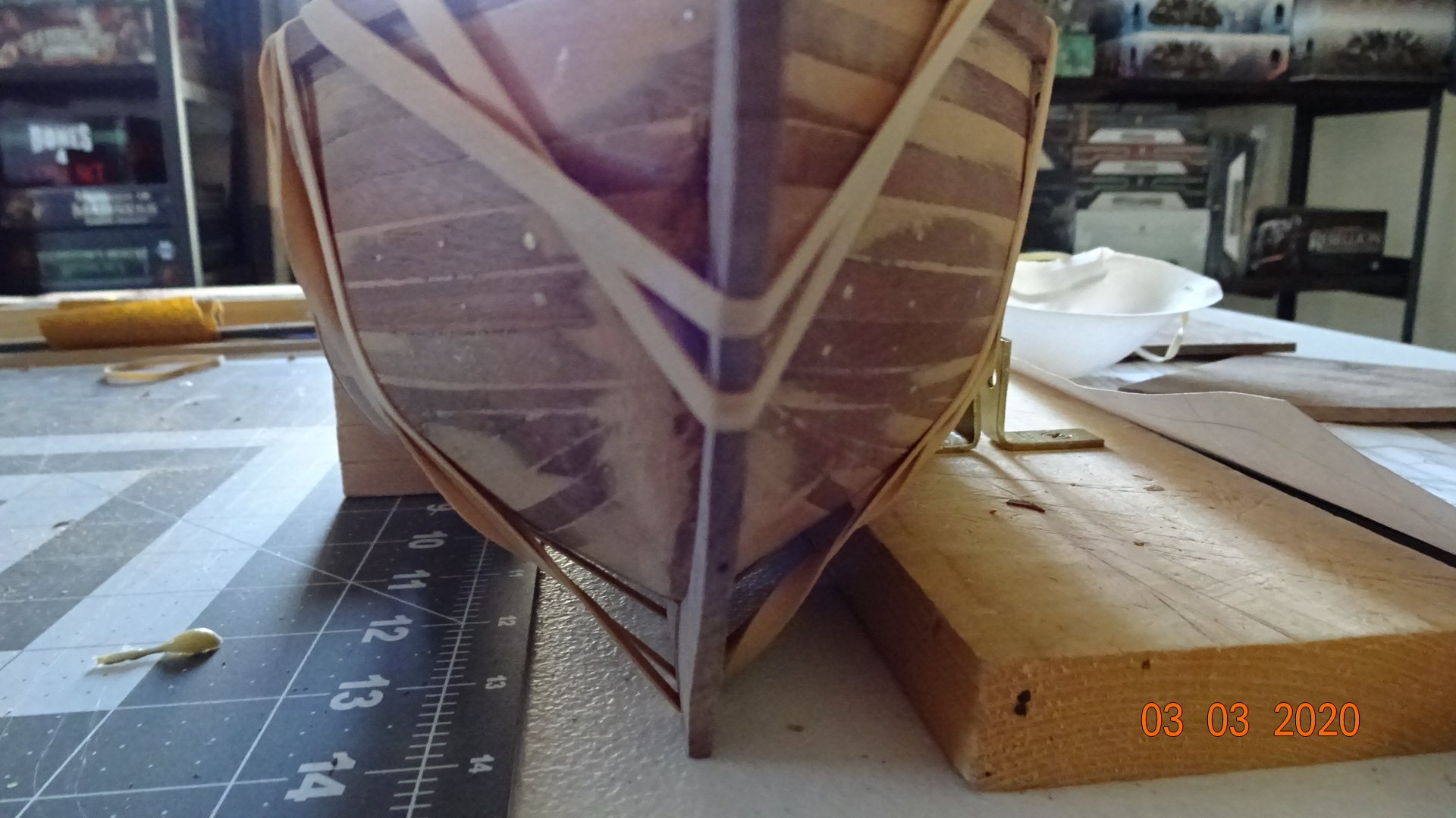
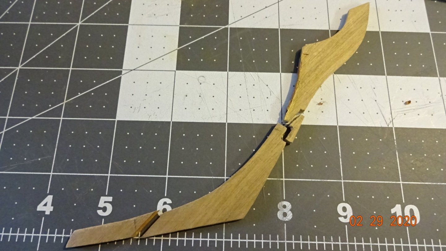
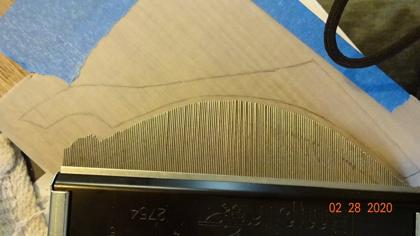
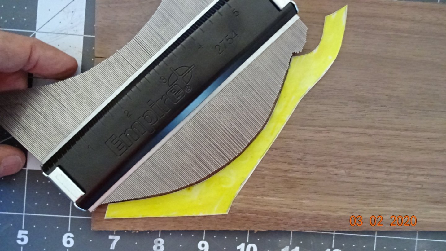
Working on the Stem and bottom keel. I busted the original Stem 🥵. After soaking I tried to bend it around the hull curvature, obviously didn't work. So I made a new one. First, took a more accurate measure of the curve. Traced the top and bottom to the Stem first, added the curve to connect them and filled in any blanks. Colored the new paper Stem and lightly glued it to the walnut wood I would use for the Stem. I made sure to keep the correct curve while placing the paper Stem on the wood. I cut out the Stem but snapped it while sanding with the machine sander . Glued it back together and attached to the hull. Also tested how the bottom keel would fit. Glued the bottom keel on and sanded it to somewhat level. While moving the model around I smacked the Stem again, and snapped a piece off. LOL Glued it back on and clamped it down. All this work in preparation of the 2nd planking. Bad news on that front 🙄, I estimate I need 40 strips but only 37 came with the model. I can mill a few pieces, maybe 4, that leaves little room for errors. And I make errors.🥵 Need to spend some time thinking how best to resolve this next issue.


- 195 replies
-
- 3
-
-
- enterprise
- constructo
- (and 1 more)