HOLIDAY DONATION DRIVE - SUPPORT MSW - DO YOUR PART TO KEEP THIS GREAT FORUM GOING! (Only 69 donations so far out of 49,000 members - Can we at least get 100? C'mon guys!)
×


DanielD
-
Posts
646 -
Joined
-
Last visited
Content Type
Profiles
Forums
Gallery
Events
Everything posted by DanielD
-
 Hi Bill, I basically didn’t even look at the kit instructions for the inside of the bridge. I made everything from scratch to emulate the virtual tour as close as my skill level allowed. I made the telephones, the gauges, the supports for the helm, designed the floor based on the actual ship, lights, etc.
 -
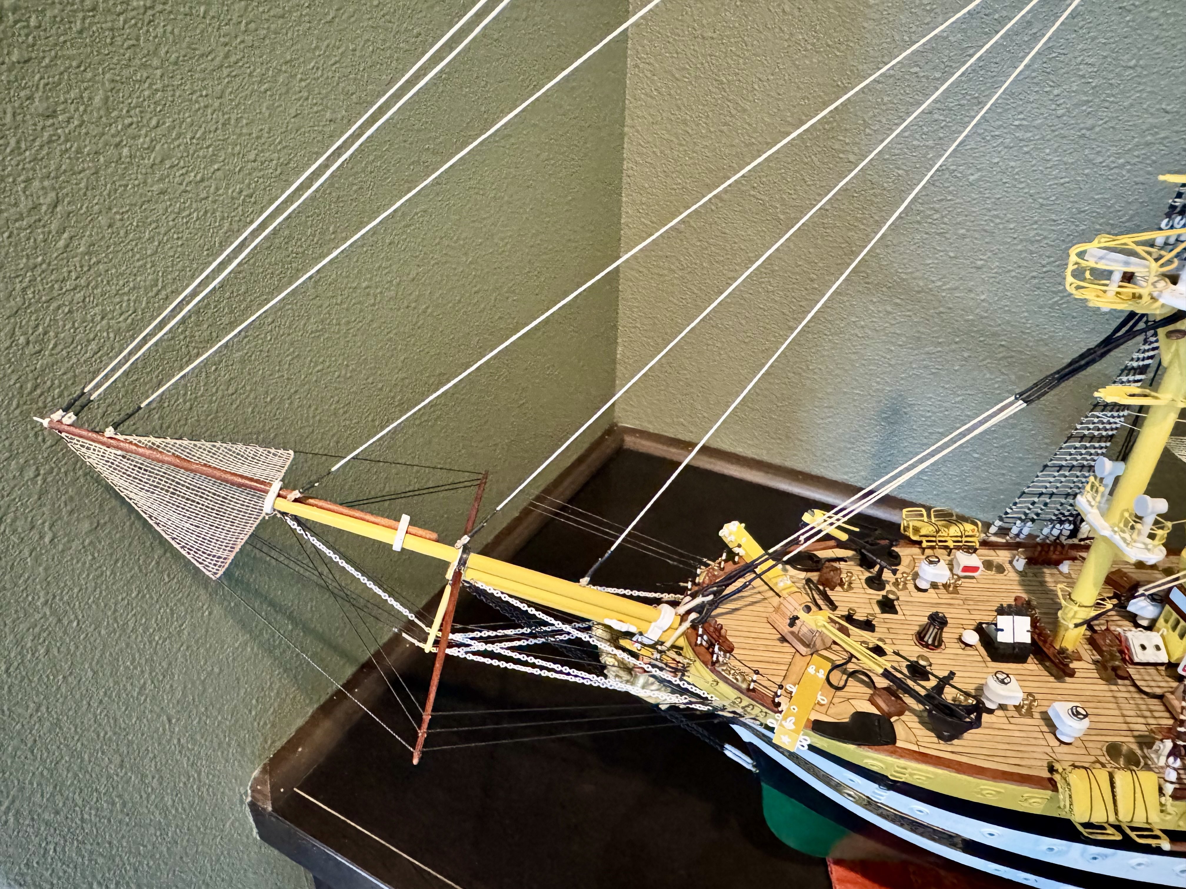
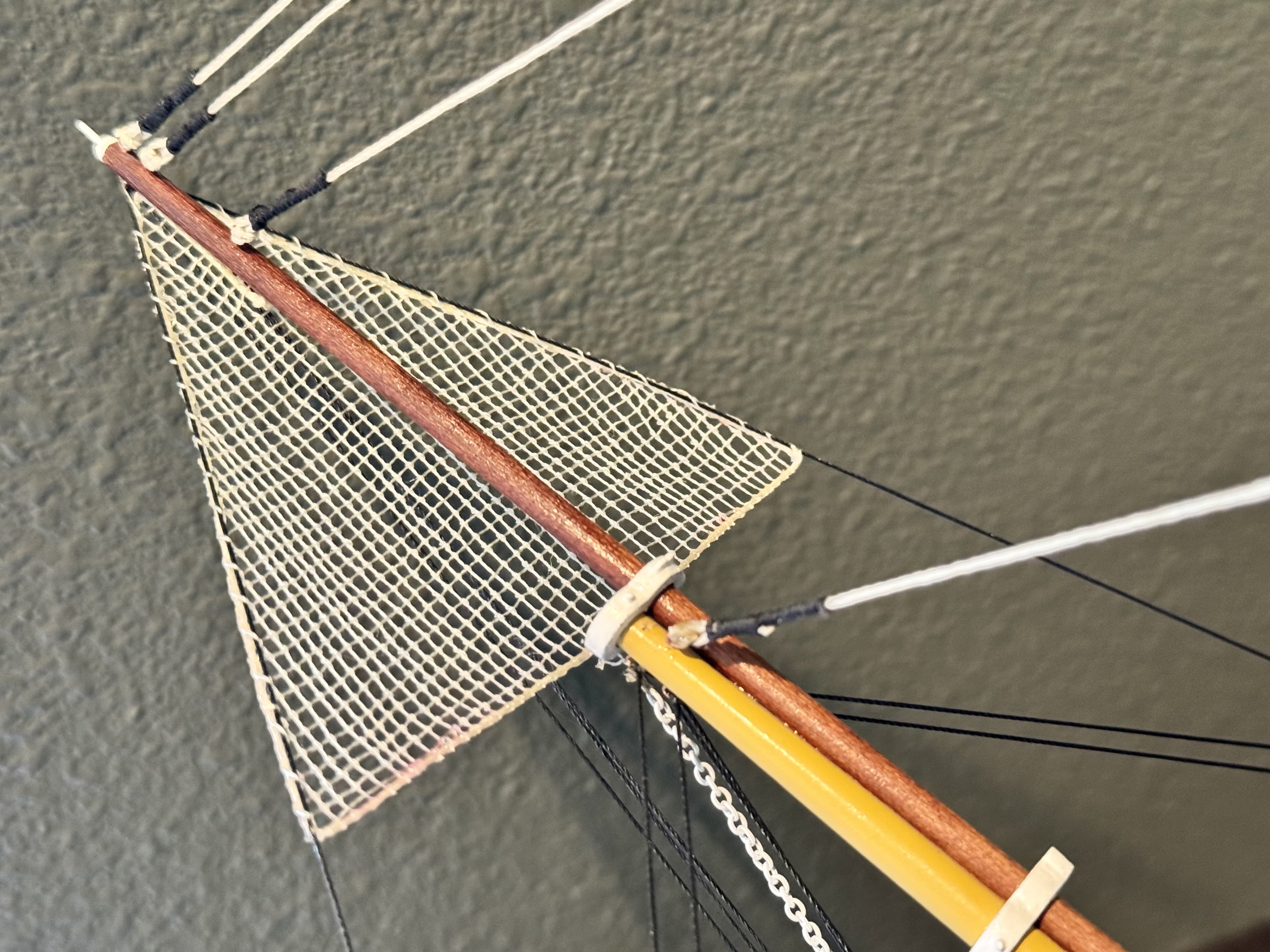
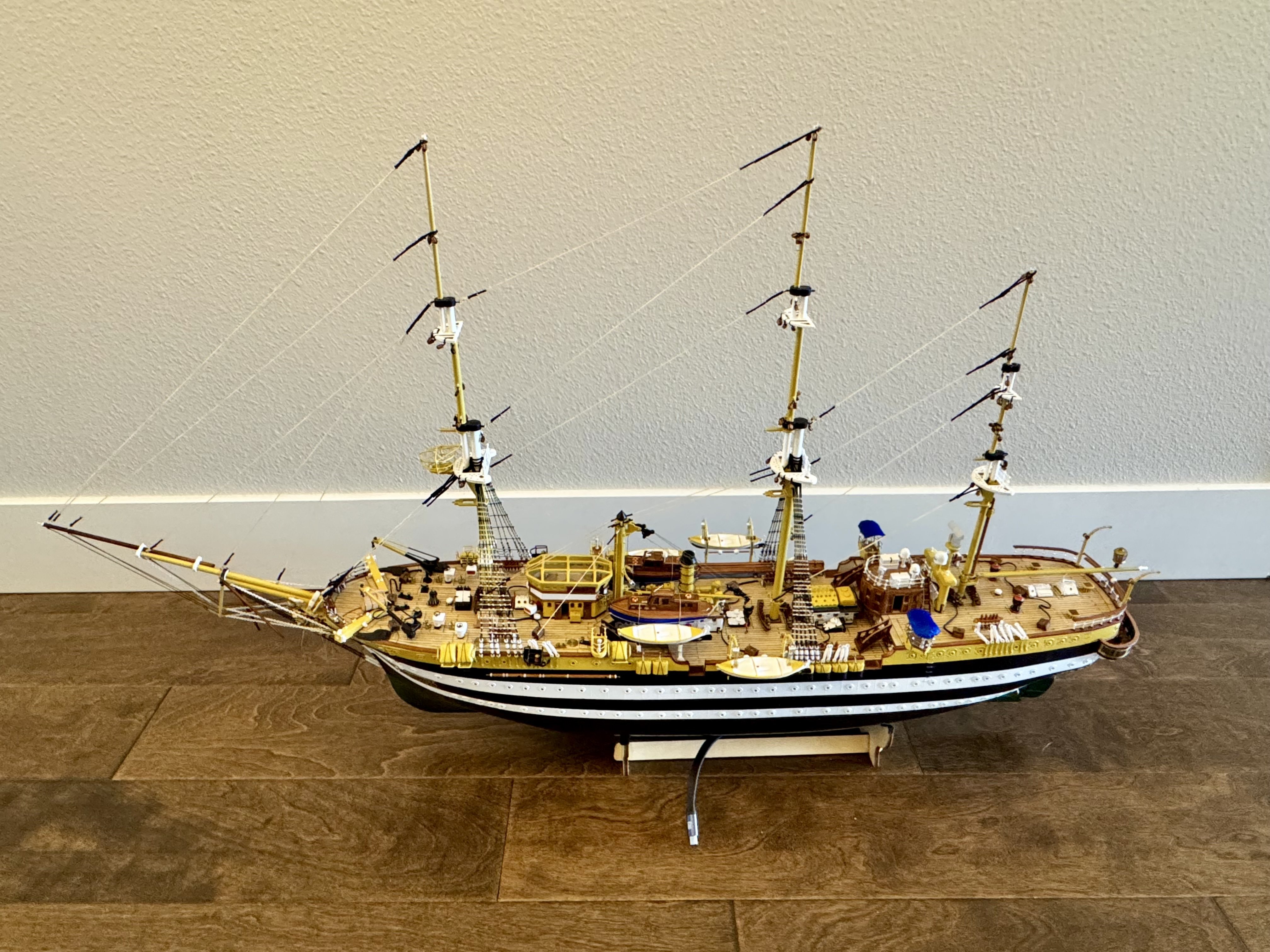
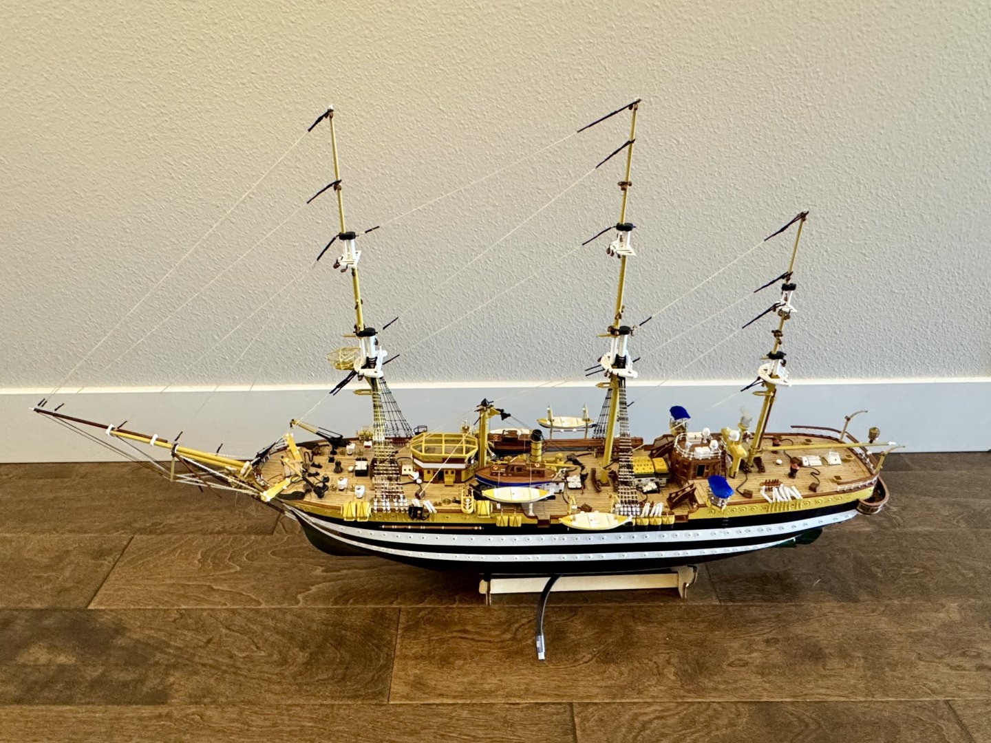
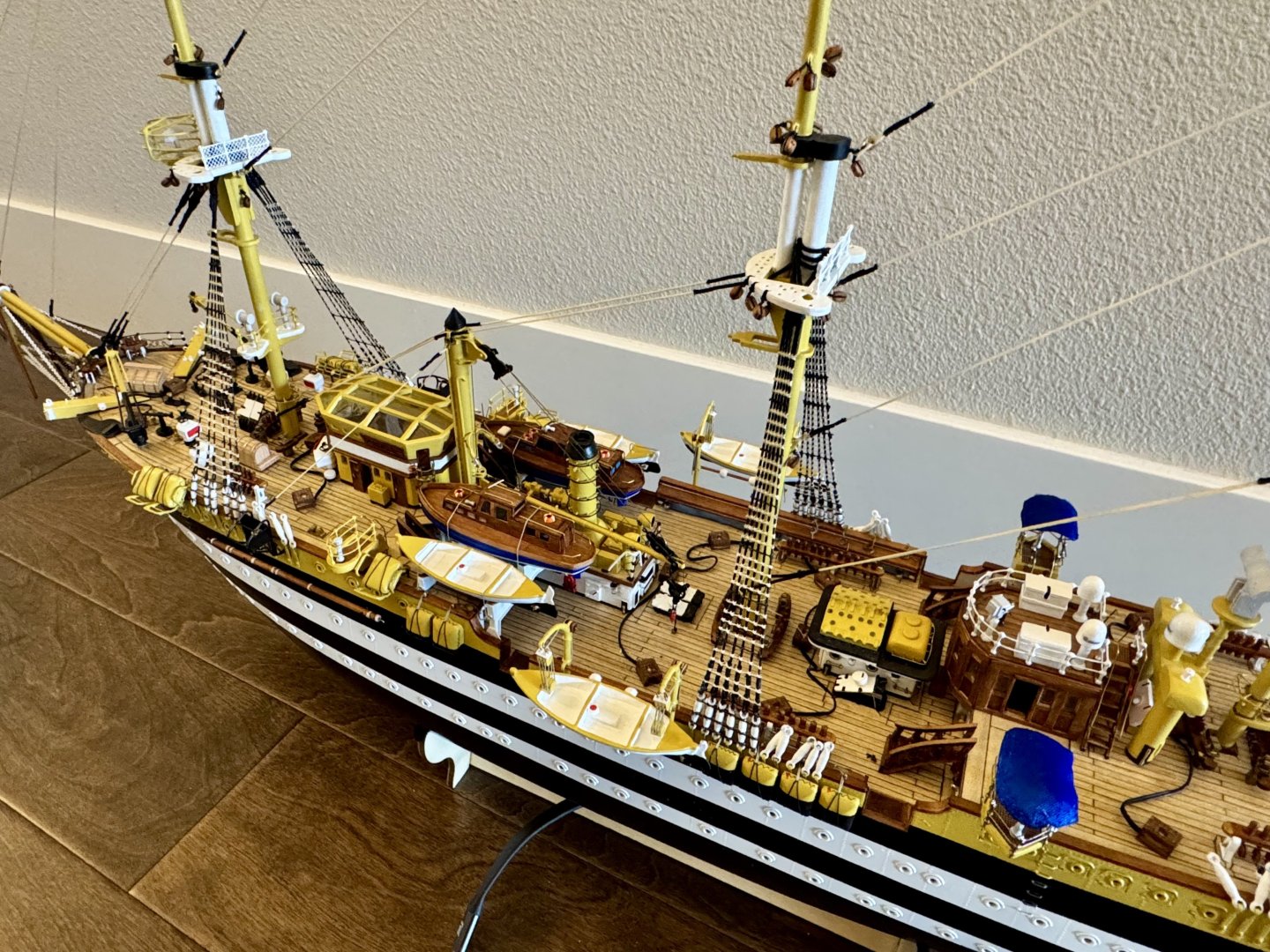
Good afternoon mates, it’s been awhile since my last update. I’ve not stopped work in the shipyard, but the work has been slow going. I’ve just finished the first of three safety nets for the bow of the Amerigo Vespucci, with over 1000 clove hitch knots at a spacing of about 1 mm square! This safety net took about 6 weeks to create.


-
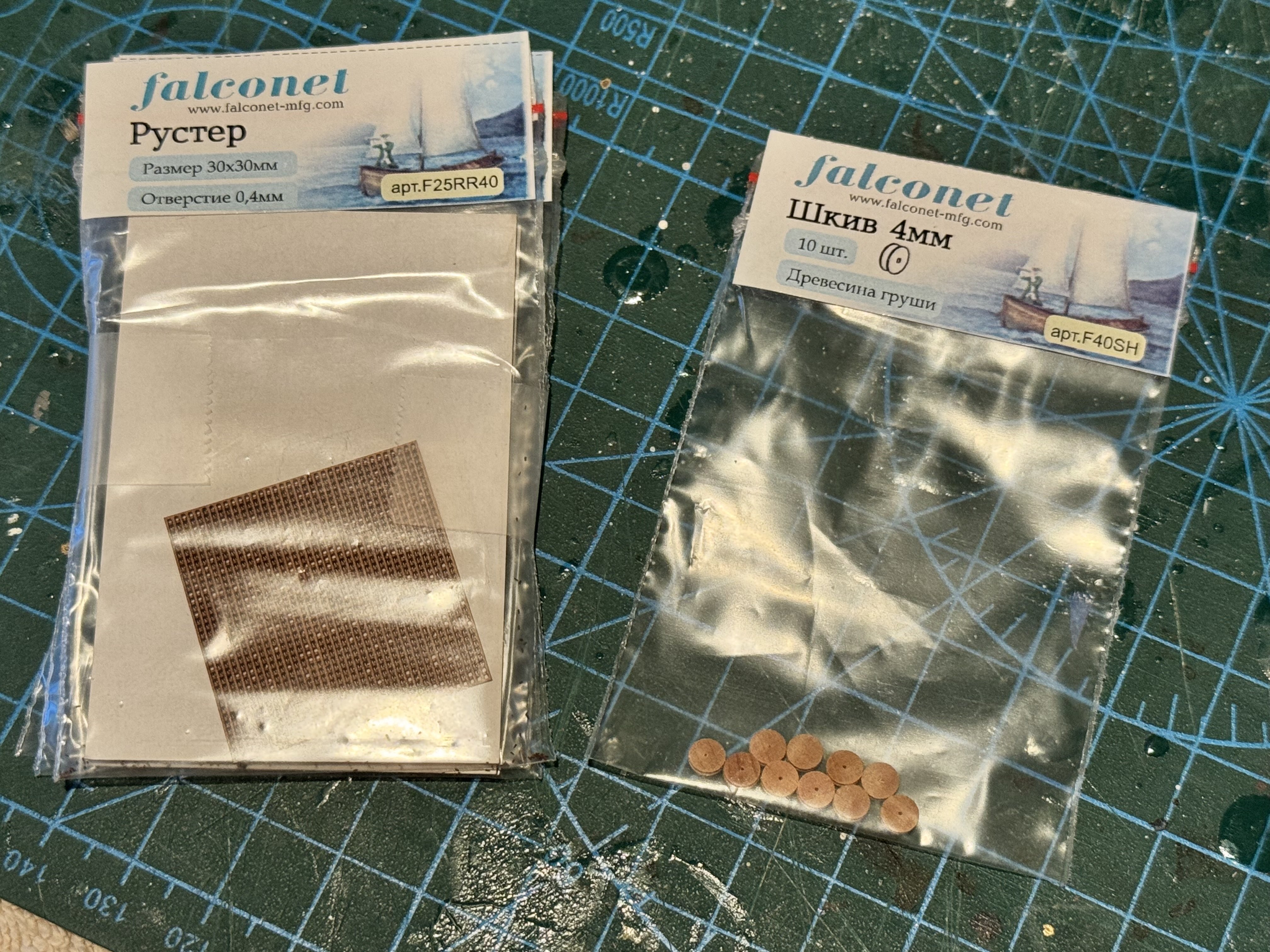
Bill, here is the 4mm wood sheaves and the 0.4 mm x 0.4 mm x 30mm square grid material that I’ve used all over the ship. Places on the deck, on the floor in the bridge, the floor of the sky bridge, and the captain’s deck at the stern. https://falconet-mfg.com/collection/rustery?lang=en

-
Good morning Bill. This is not included in the OcCre kit. I made it by using laser cut 1mm square prefab grating that I purchased from a company in Canada along with a bunch of very small wood pulleys so that I could make the AM specific running rigging pin racks. I’ll try to remember to take a picture of the packaging when I get home. Great product but very fragile due to the small size.
-
Yes, you could have a separate circuit, but for me it was the only two LEDs on that circuit and I wanted the OR situation. Diodes are cheep, less than a $1 for like 5 of them and can be setup inside the hull so less wires heading into the hull from the control panel. But this is just me…you build your however you like.
-
I saw these and went a different route as I needed more than three out. Also, once you have everything working and before you seal up the hull, run a bead of hot glue across the switches to glue them shut. I have heard that these have a habit of popping open and if that happens after you close up the hull, you are screwed.
-
Hi Bill, let me see if I can remember…I believe the structures you labeled A and C and the exterior lights on B are all part of the deck lighting circuit. Well almost that is. The fore part of the structure C is the chart room and that is a part of the deck lights while the rear storage compartment of the same structure is, well on a special circuit as is the interior light of structure B. I used a diode on each the port hole circuits to create a “third” circuit. The goal is this, when one port hole circuit is on and the other off, the internal lights of Structure B and the storage compartment of structure C are on. If you switch the port hole circuits with the second one on and the first one off, opposite the set above, the internal lights of structures B and the storage compartment of structure C are also on. And of course, if both port hole circuits are on, so are the internal lights of B and the storage compartment light. This adds a level of complexity to the lighting that is unexpected yet very easy to do, giving the model a more authentic look. You are the first person to either notice or question this. Good job!
-
Hi Bill, yes and yes! I’ve added tons of features not in the kit just by looking at the virtual tour. Each piece of equipment I worked on I would go view the tour and add as much detail as I could.
-
Bill, part 1 answer: those brass pieces are found all over the ship! They are there to manage the ropes that are pulled around the deck to operate the sails and other operations of the ship. Basically, they are there to protect the ship and ropes from being damaged. part 2…I’ll have to wait until I get home to be sure, but what I remember they are just high intensity 3mm LEDs. Update: https://a.co/d/huSaGT5 this is what I purchased. I run this “channel” at a higher voltage which makes them brighter, but do not exceed what they are rated for.
-
Bill, these are not part of the kit. I manufactured them from scrap brass round stock placed in a lathe and sanded the center to create the hourglass shape.
-
Hi Bill, yes! Planning what you want to light up is essential at this stage, if not before. The mistake I made was not creating the raceway for the wires in the bulkheads before I assembled them onto the false keel. The "raceway" is a path for the wires to run under the deck to get them where you need them for eventual lighting. Things to consider: 1) don't put the raceway close to the deck, meaning create holes for the wires 1/2" or so below the deck. The reason for this is you will eventually be drilling holes in the deck for equipment to attach to. If the wires are close to the deck surface, you can easily drill into and sever a wire as I did in my HMS Terror (see that build log for a description of how I had to fix it). 2) Make the holes for the wires fairly large. I made mine 1/4" in diameter and that just was not big enough but it was the only "long" drill I had. I made it work but had to force some wires through a crowded hole or two. I had to use a long drill because I made the mistake of not drilling the raceway holes before attaching the bulkheads to the false keel. This would be so easy to do while the bulkheads are individual pieces. Make a list of what you want to light up! The obvious choice will be the port hole lighting. I chose to have two circuits to give it an authentic look. One circuit for a random selection of 1/2 the port holes, the other circuit for the other half. I can choose to have one set or the other on, giving the look that is in most of the night images, or I can have both circuits on and have all the port holes lit up. Plan what you want to have lit on deck. I have lighting in the main bridge, the chart room, the storage room (just behind the chartroom). Things that I did not plan for but I thought were essential and had to do some retrofit: deck lighting behind the main bridge that shines down on the deck and lighting on the foremast that shines down onto the deck. Things that I did plan for were the lights along the storage bunkers on the main deck, the night lighting circuits (3 colors), and the motor that turns the propeller. Lastly, figure out how you are going to power the LEDs. If using a battery on board like I did in my HMS Terror, plan an easily accessible location to replace the battery. Depending on how many LEDs you plan to use, you might need two 9v batteries so takes up a lot of room somewhere. In my case, two 9v batteries are not enough! It is enough voltage-wise, but not enough current-wise, meaning that I can not have everything turned on at once with just two 9v batteries. This is why I chose to power my AV externally. From reading my blog you can see that the switches are off the ship and will be placed in the pedestal eventually and power to the ship is through a USB-C cable. I will eventually power my ship with a 12v 1.5 amp power brick that plugs into the pedestal. This will allow me to power everything at once without issues. I would not recommend using AA batteries. These are only 1.5 volts each, which means that you will need to have 6 AAs to match the voltage and current rating of a single 9v, so 12 AAs to have the current to almost power everything at once. Well, I'm off to work for a bit, I'm sure there is a lot more I can offer on this subject, but will need to wait until another time.
-
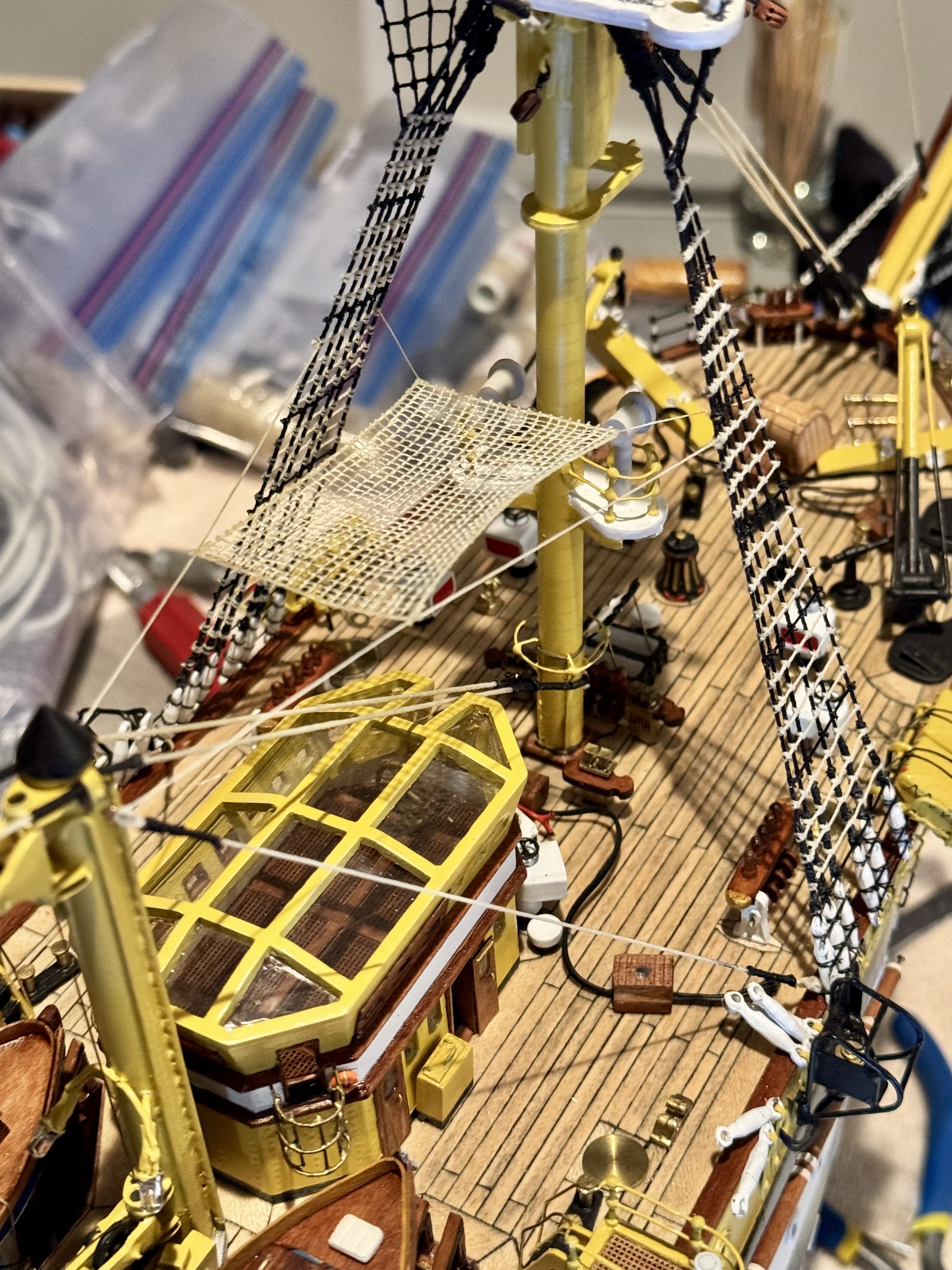
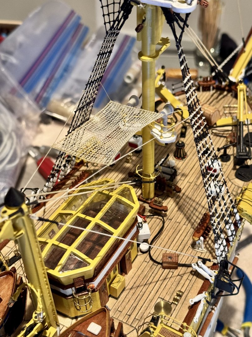
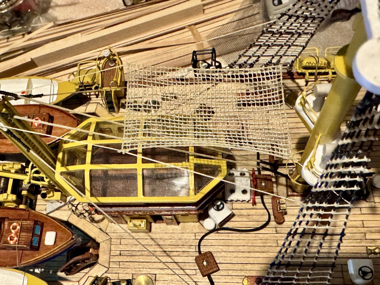
Good evening mates, it’s been some time since my last post. Progress continues on my Amerigo Vespucci, although very slow. I have new job responsibilities that have consumed much of my time, leaving little for shipyard work. Here are a couple of images of what I’ve been up to. Apparently model builders strive to do things the most difficult way possible. In this step I needed to make a net to hang on some rigging. Instructions call for a pre fabricated plastic net, which, well…looks like plastic. So I attempted to manufacture a net from thread. Here is my attempt at a 30mm x 50mm net with 836 clove hitch knots at approximately 1.5 mm spacing, which took approximately 10 hours to build.
-
Good morning Bill, as promised, here is a link to an image of the AV deck which shows one of the light boxes use for the famous night display. Not displayed here due to copyright. As near as I can tell from my research, there are six of these for each mast. https://media.istockphoto.com/id/1490897723/photo/palermo-amerigo-vespucci-training-ship.jpg?s=170667a&w=0&k=20&c=MfF8VYDDyRw46gWmhsLYtrhmJyiI7P9a02Ev7uFSrrM=
-
Good morning Bill. The easiest way to describe what I’ve added is by taking a look at this picture. https://www.dreamstime.com/stock-photo-ship-amerigo-vespucci-ropes-wood-italy-image73807010 I can’t display it here because it’s a copyright image, but if you take a look you will see a lot of detail that is not in the kit of the AM. Here you will see that there are metal black painted bars placed among the rat lines. More concentration at the bottom, I think 4-5, then every 5th rat line has been replaced with a bar. I have seen other pictures of sailors standing on these bars in uniform as they enter a port. You will also see that the stays (the vertical ropes) are black while the rat lines are light. This is different than the other ships I’ve built and I didn’t know exactly why this was done…until the first time I turned on my night light option. The lighter rat lines easily pick up the colored green, white and red lights and make a beautiful display. Had these lines been dark, brown or black, little color would display. It was an ah ha moment for me. It took me a long time to find these lights in any of the online pictures, but once I knew what I was looking for I started to see them occasionally. They appear as about 12”x14” boxes with a heavy power cord that goes below deck. They do not appear to be permanent, but something that can be put away when not needed, which makes sense. I’ll see if I can find a link to an image that shows one. I used a sticky gel glue dot, like used in scrapbooks, to adhere my boxed lights to the deck. I did this so that once I finish the ship, I can easily move the lights around a bit to get the best appearance.
-
Good afternoon mates! It’s been some time since my last update but the shipyard has been busy. I’ve been working on the rat lines and all those half hitches. I have completed the lower foremast and the mainmast rat line sets. In the case of the Amerigo Vespucci, every 5th line is made out of a metal bar that the crew uses to stand on when making a show of coming into port. I have included this detail in my version of the AV.
-
New Member Dale Mierzwik of Northern Colorado
DanielD replied to DaleMierzwik's topic in New member Introductions
Welcome aboard mates! -
Yes, please! I’ll be getting to that soon and I have no idea how to. Thanks!
-
Good morning Bill. If you do a web search for AV dry dock you can see pictures of the hull with its rivet pattern. What I did is not accurate exactly, more like a good representation of the pattern. There is no possible way to get the rivet size and pattern accurate, so I used what I could get (smallest rivets for railroad) and just made it work. In the end, with paint and all, it turned out great, in my opinion. There are so many other things attached to the hull for visual interest, it’s only when you look close do you actually see the rivets. Would I do again? Yes, absolutely!
-
Welcome aboard mate!
-
The LEDs are mostly not aligned with the port holes, so holding the air brush perpendicular to the surface being painted does not put enough paint on the LEDs to worry about. Many modelers will paint the final color before drilling the holes and then install the port holes (grommets). This will leave them brass, but the actual AV has the port hole painted the same as the hull in that area, so that’s what I did. Unfortunately, paint does not stick well to brass, so painting the grommets first and then install later is messy and requires touch up. So I installed them before primer and paint to get the best look for me. I had to use an etching primer, but still doesn’t stick great.
-
I drilled out the holes and added the grommets that come in the kit to represent port holes. The rain gutters are not a part of the kit, one of my added features.
-
I didn’t worry about it, but next time I will do as Mike suggested, drill port holes after primer and sanding.
-
Bill, you can use your 3mm for everything. The 3mm is necessary for the deck lights as the 5mm are way too big. Inside the hull I used 5mm to give off more light, but if you paint the inside of the hull off white, you will get a lot of reflection and all will be good. If you are only doing one set (circuit) of port hole lights, you won’t need the compartments like I did and just place 2 or three LEDs between each bulkhead total. If you do the compartments version, I just used one LED per compartment.
-
Bill, as you know, in my version of the AV I have the two port hole lighting possibilities. In order to achieve this effect I had to create compartments within the hull for each section that I wanted to light. Then in each section I employed a single 5mm warm light LED. When I wired everything together I randomly connected some compartments to cabinet light circuit 1 and the rest of the compartments to circuit 2. Once the hull completed I drilled the port holes following the plans. If all my calculations were correct the port holes should line up in the middle of the compartments. Thankfully it all worked out.