DanielD
-
Posts
650 -
Joined
-
Last visited
Content Type
Profiles
Forums
Gallery
Events
Everything posted by DanielD
-
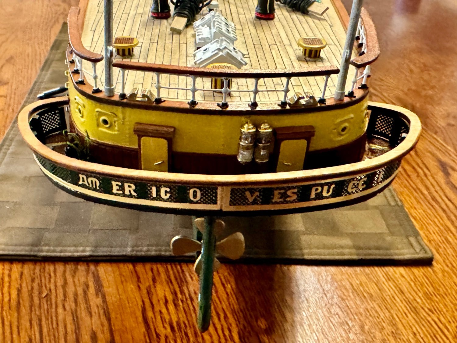
 Oh, and one more thing, she finally gets her “Ships Name”.
-
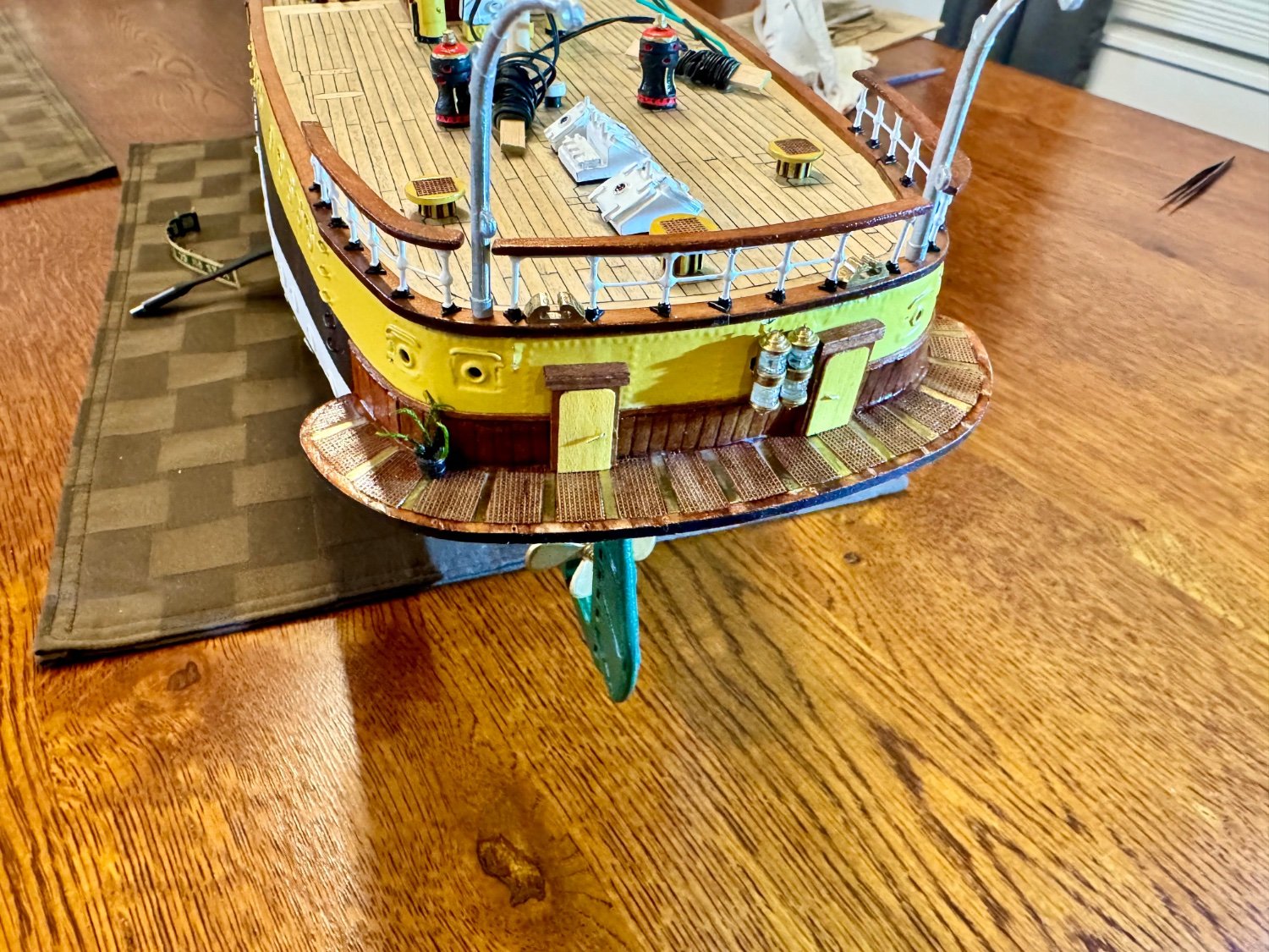
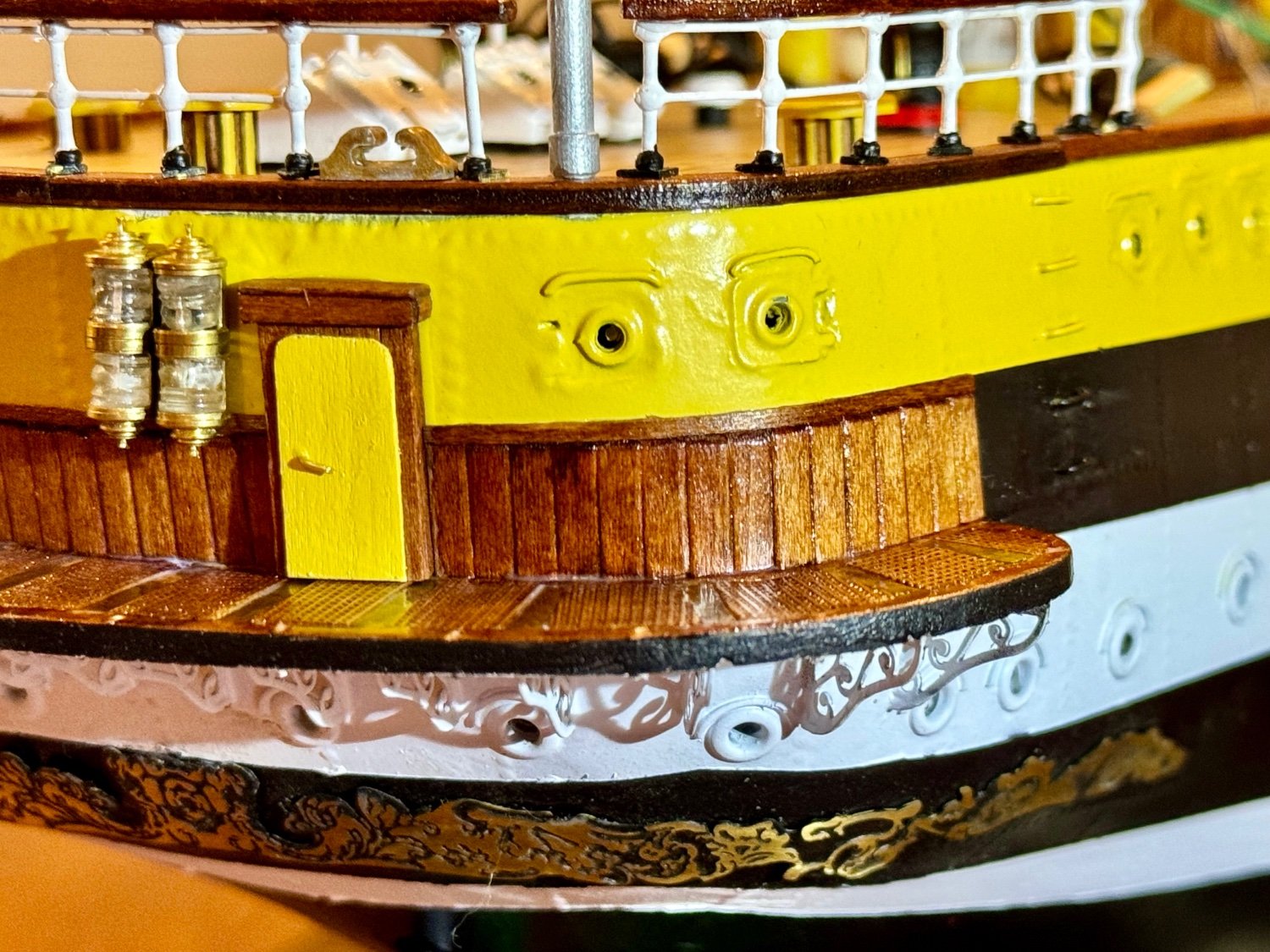
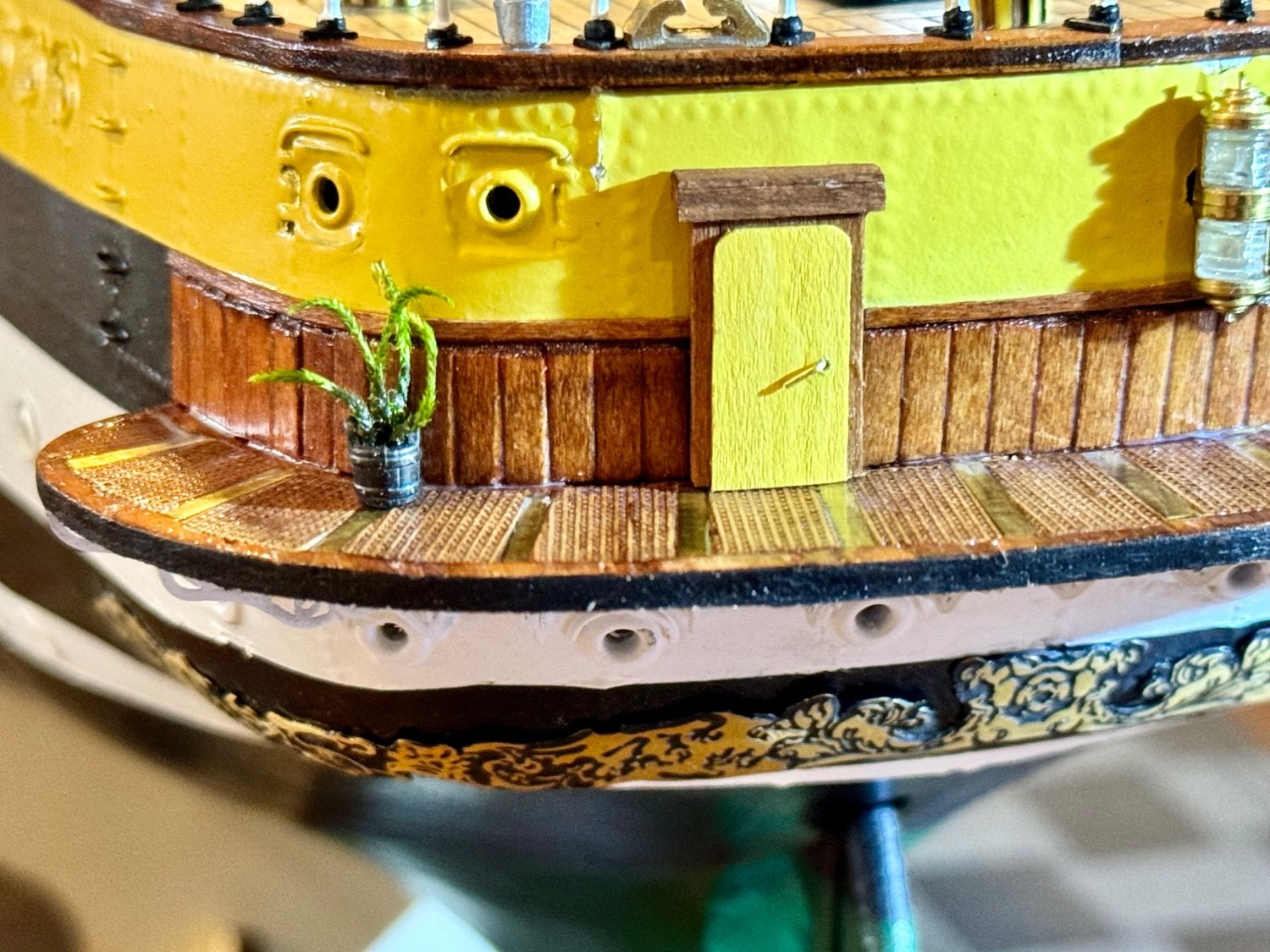
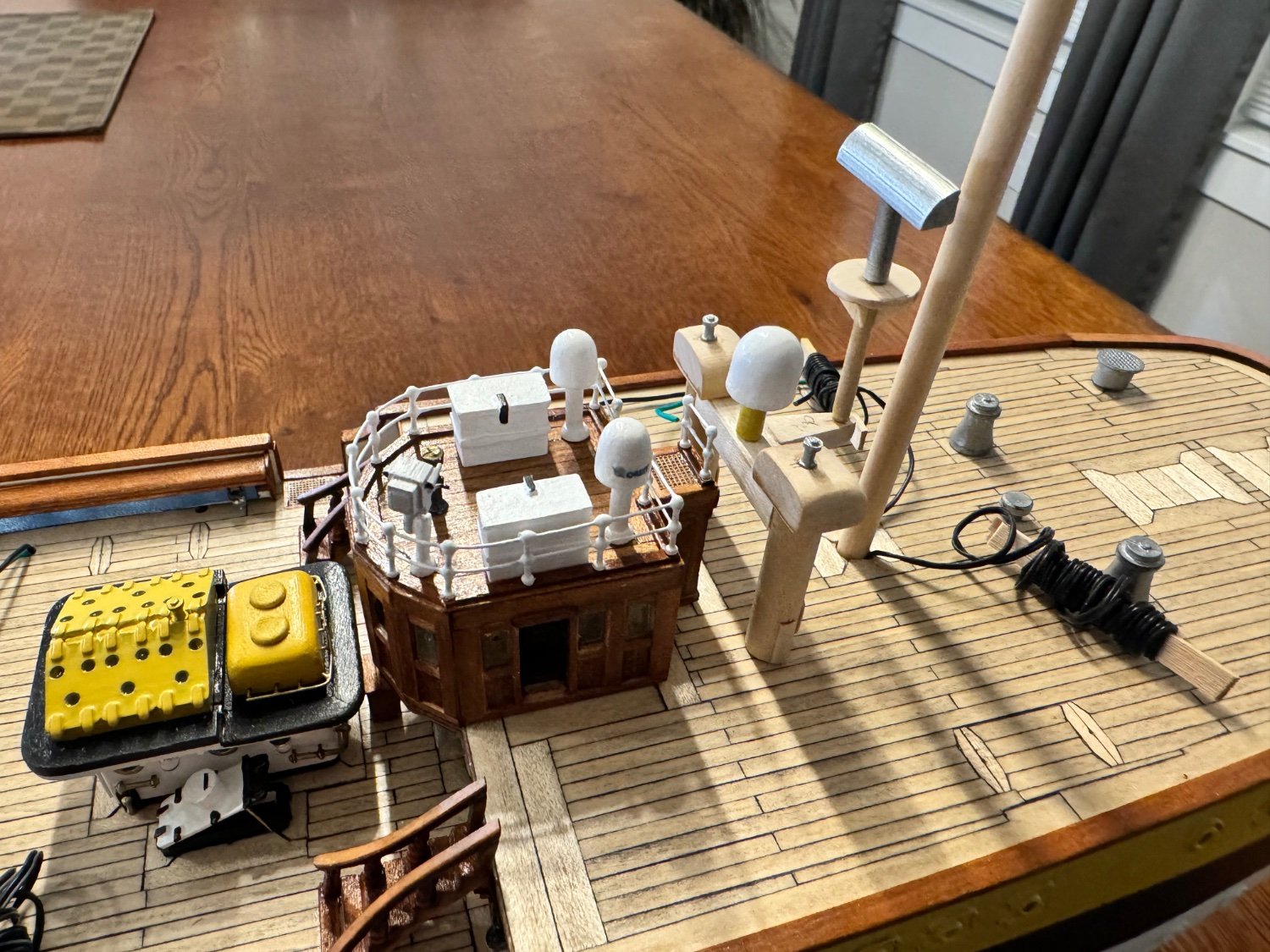
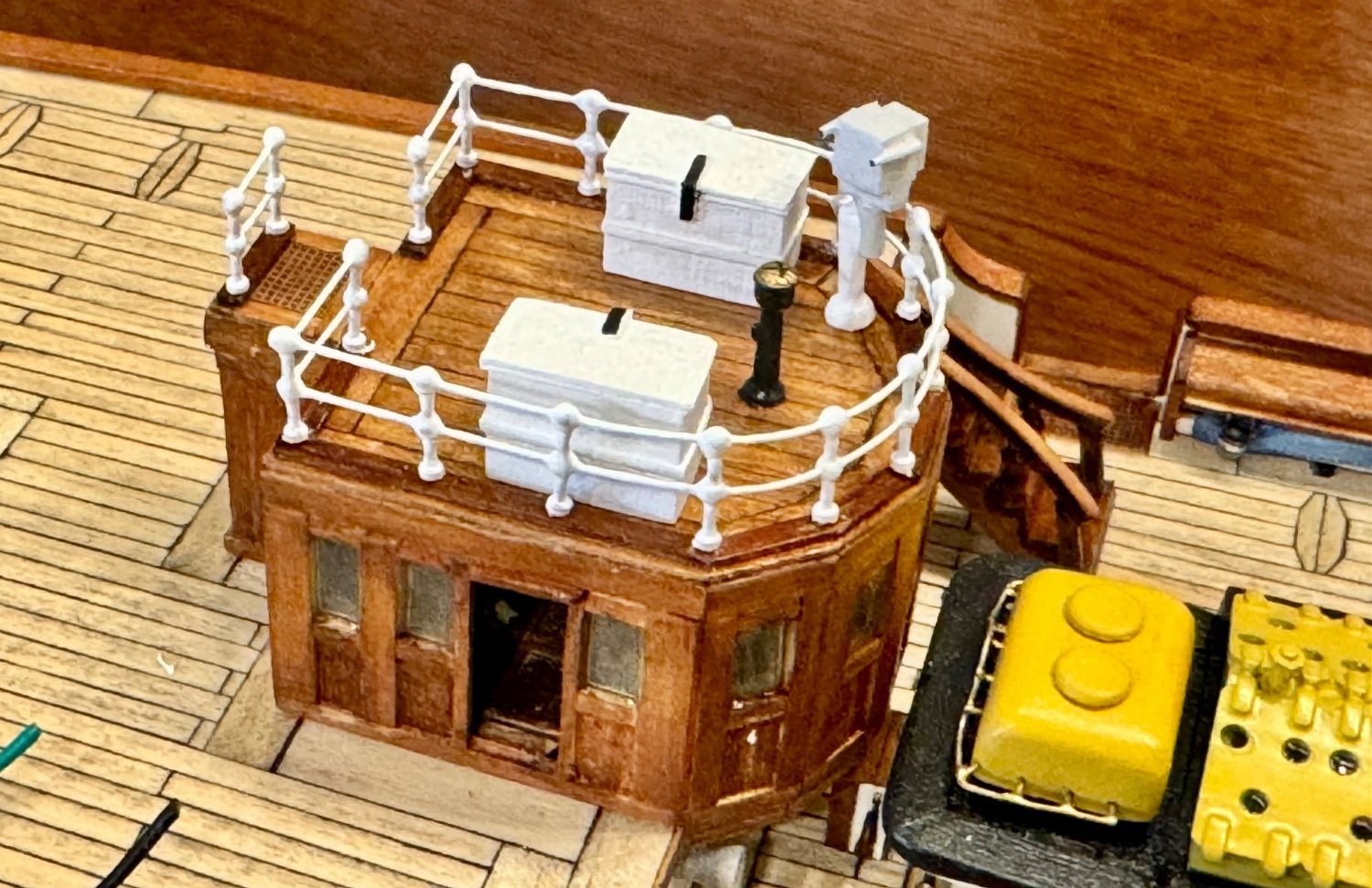
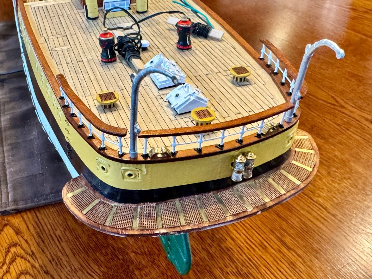
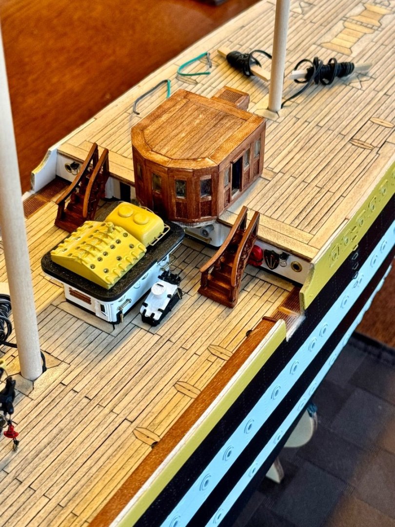
Good evening mates, I hope you all had a wonderful weekend. I had some time in the shipyard today and needed a new project so I decided it was time to build the captains deck located at the stern of the ship. Outside the OcCre plans, I built the deck with micro grid to better emulate the real AV. Along with adding the doors, I built, what in the building trade is called wainscoting, but I have no idea what this feature is called among the mariners. Basically, some vertical planks topped with a chair rail, only this version sits out in the elements.


-
Good evening mates, today I was able to spend a little time in the shipyard to finish the stern railing. A tedious process, but it looks great.
-
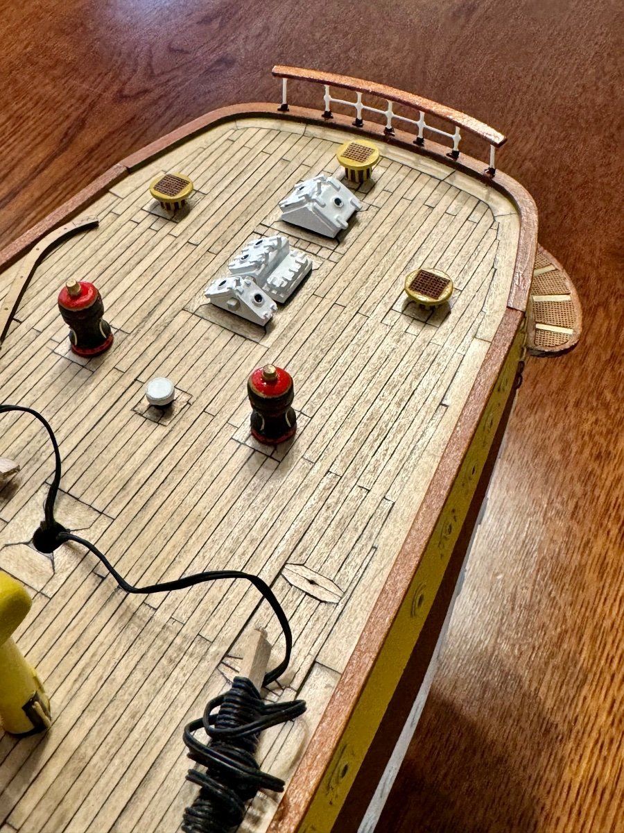
Good evening mates, it’s been a few days since my last update. I’ve been working on the stern deck equipment and just started the railing. Takes so long to do these little projects…

-
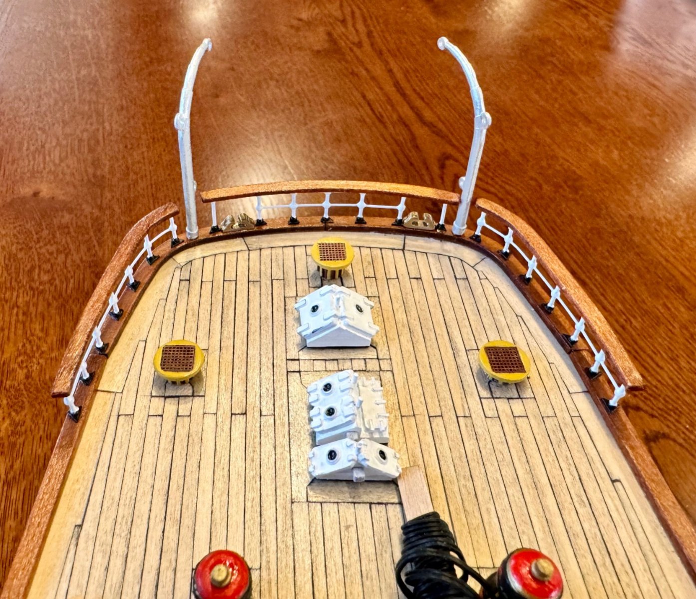
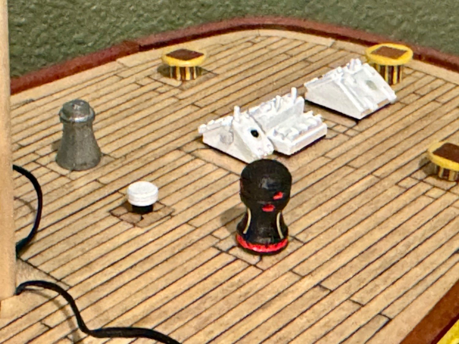
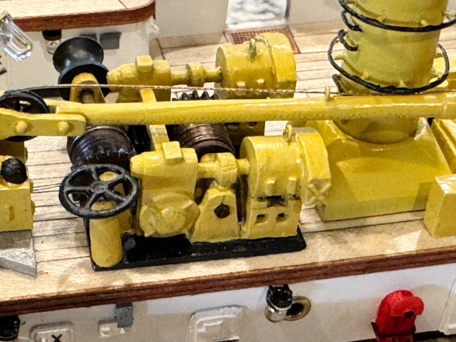
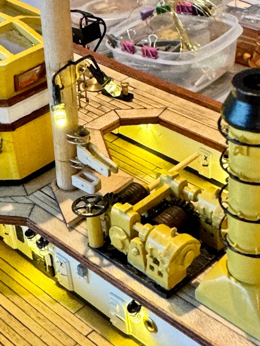
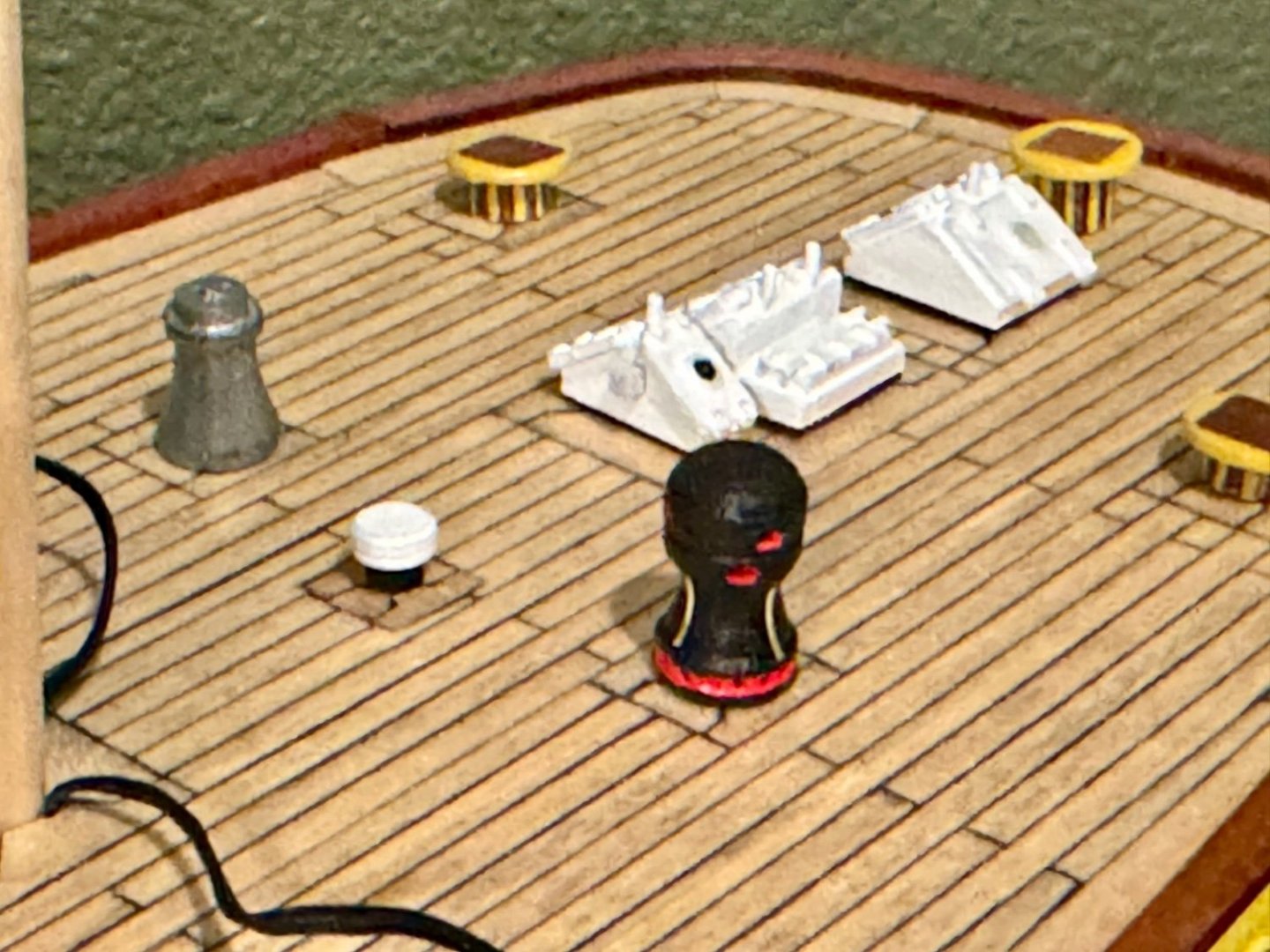
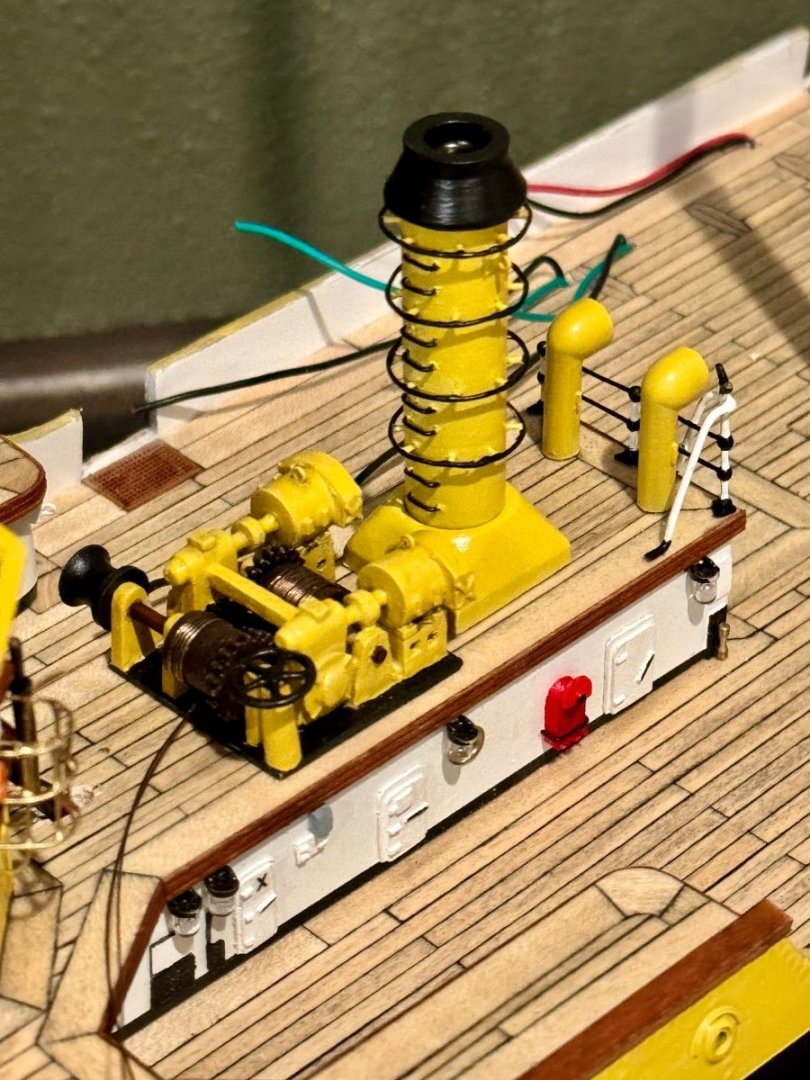
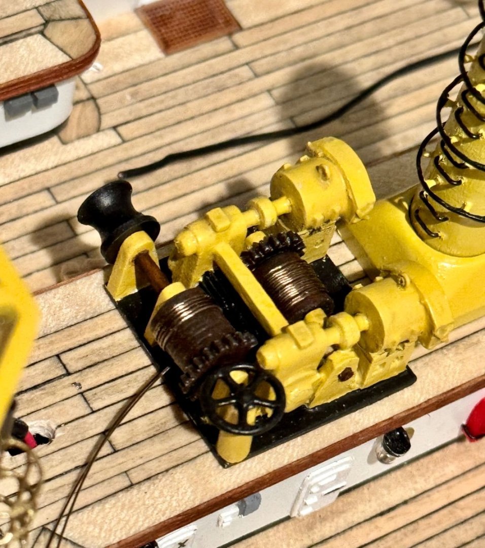
Good evening mates, this week has been slow progress due to the small size of the stern deck equipment. Today I found myself scratch building a windlass as the ones supplied in the OcCre kit are nothing like what is onboard. I still have a little detail work to do, but the main windlass structure is complete. (The one on the left is what came with the kit)
-
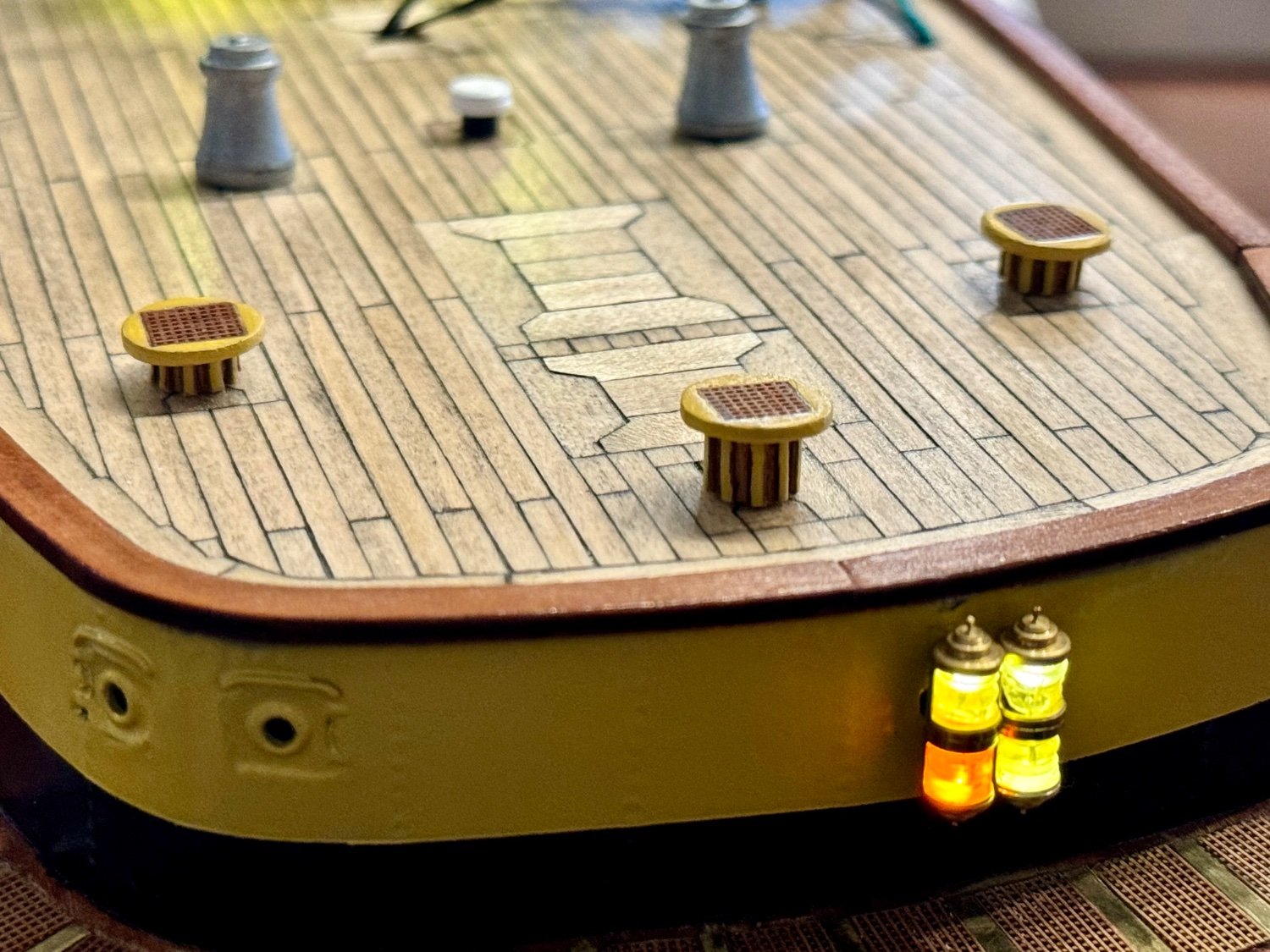
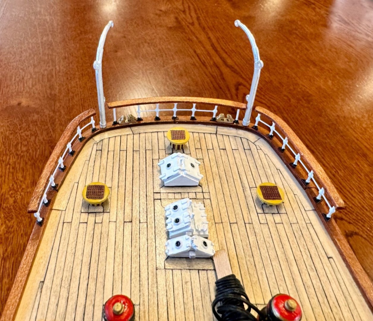
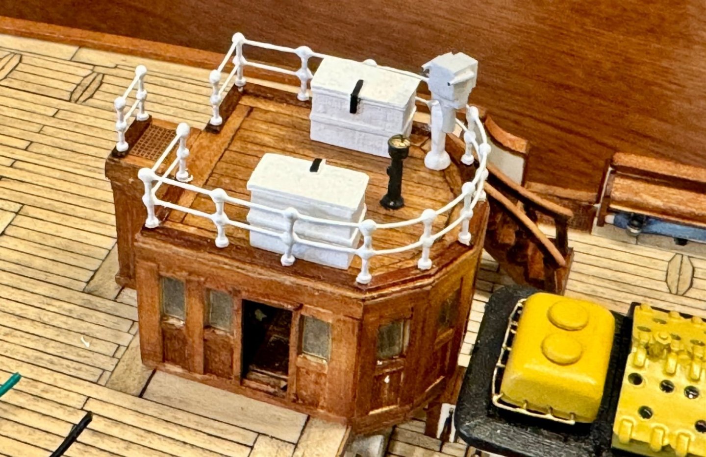
Good evening mates, I hope you all had a great weekend. I’ve been working on some detail work on the stern deck, which seems to be taking a long time! In this update I’ve added a fire house hanger, an access hatch, and some equipment covers. All these objects are from scratch as either not included in the OcCre kit or, in the case of the equipment covers, not very realistic.


-
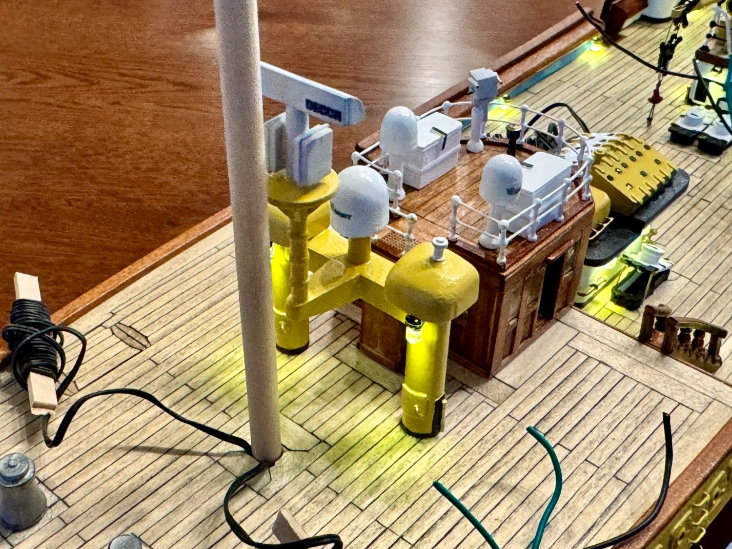
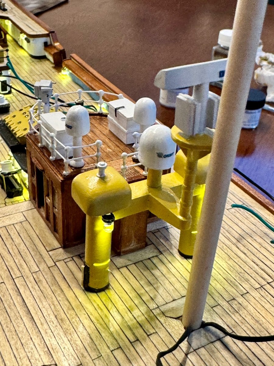
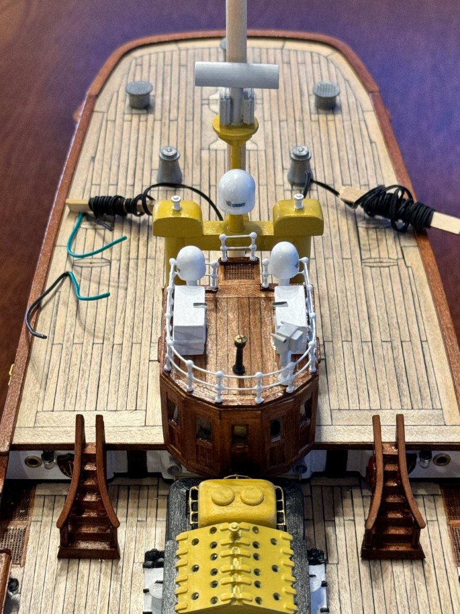
More time in the shipyard as temps outside have been below freezing and can’t go anywhere. So I have finished the antenna farm and added unplanned lighting as per the images I found of the real AV. Now on to a new project.


-
Good evening mates, it’s a winter wonderland here so that means more time in the shipyard. The last few days I’ve been working on the AV radar antenna farm. Totally off OcCre plans, but very much like the working Amerigo Vespucci.

-
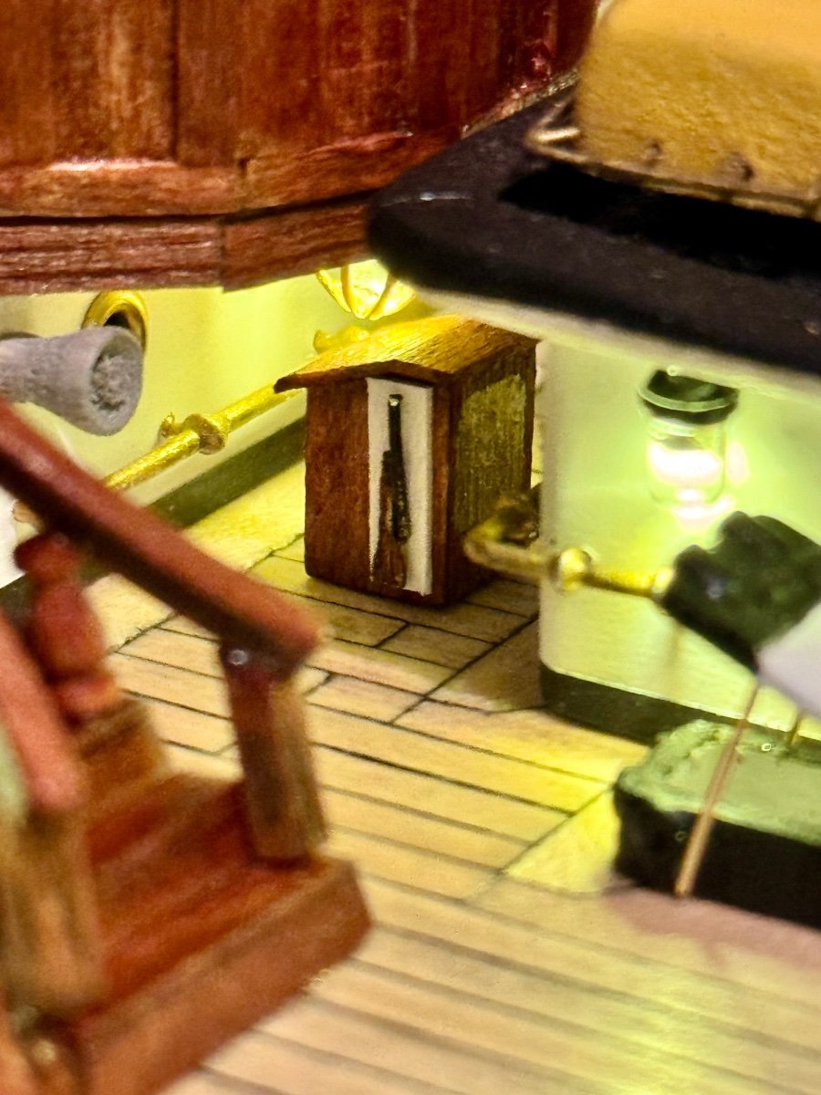
Good evening mates, slow progress this week. I did make the lectern narrower, more like the actual AV (see above) and also working on the railing and equipment on the top of the bridge. Like I said, slow progress.

-
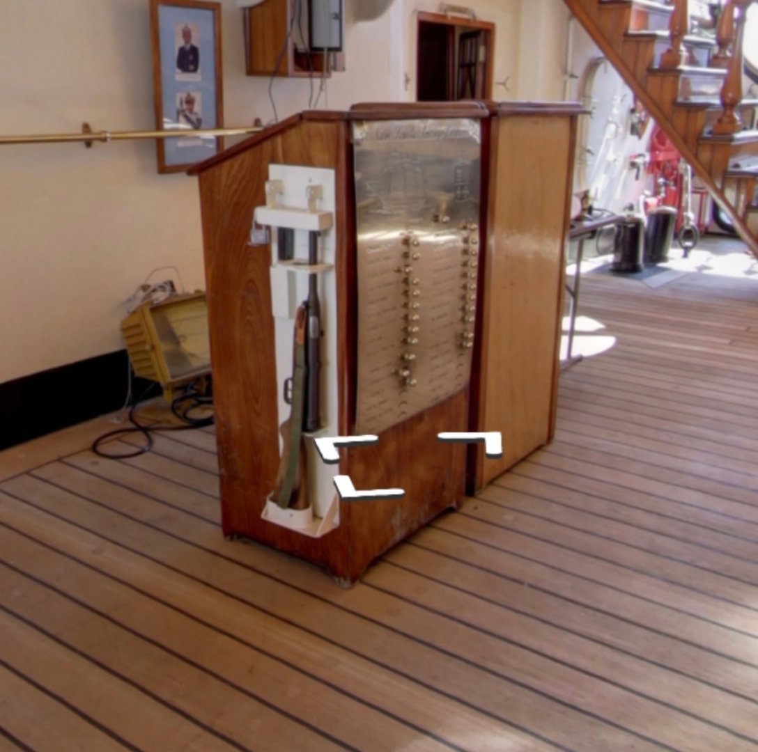
Good evening mates, today I spent time in the shipyard working on some details I forgot. In this image reproduced the lectern that exists on the Amerigo Vespucci. The second image is an actual shot of the AV. I think I need to make it a bit narrower, but that’s an easy thing to do. The hard part was a very small rifle, jus 6-7mm long and still make it look like a rifle.

-
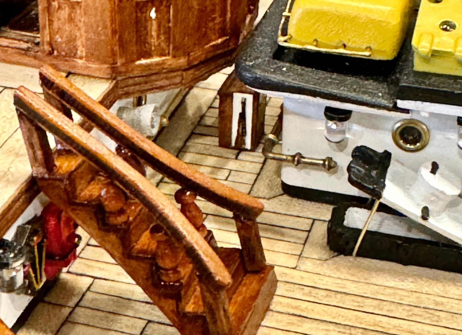
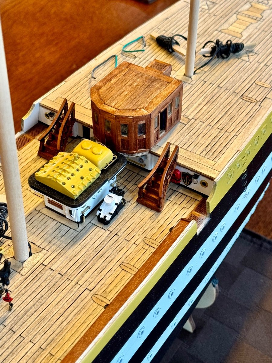
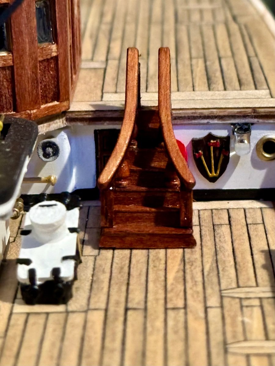
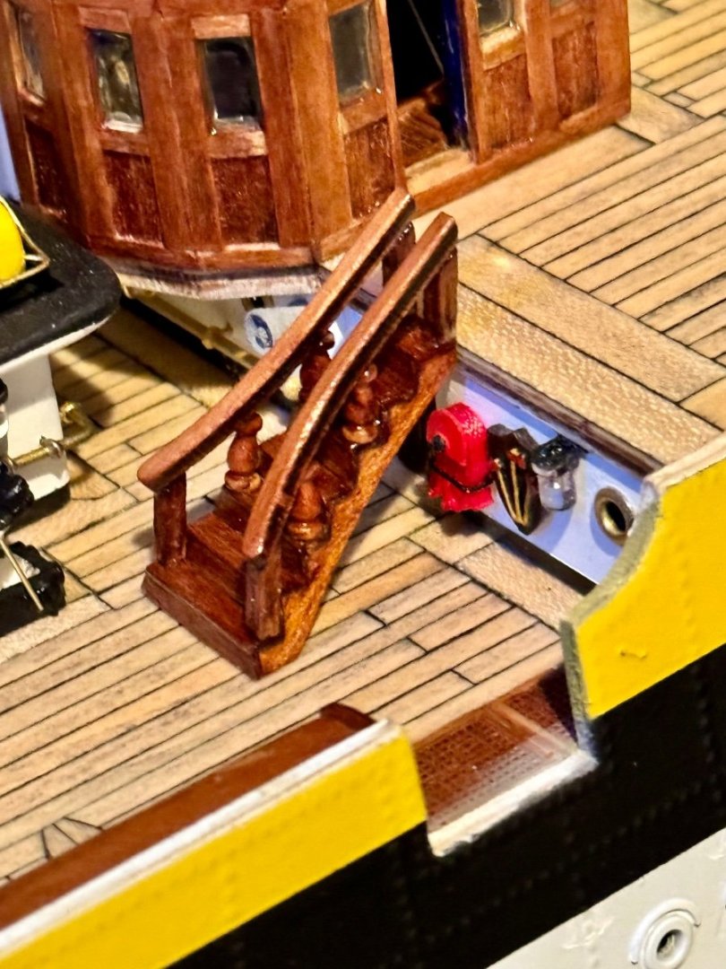
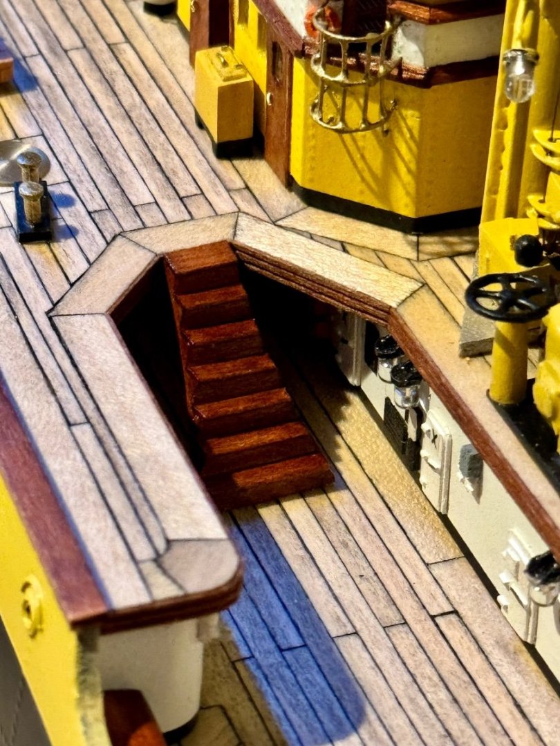
Good afternoon mates, I hope you all are having a great start to 2024. This week progress has been slow but I finally have finished all four grand staircases, two from the mid deck to the fore deck and two from the mid deck to the stern deck. Finishing these features about completes the hardware for the ships mid section. Now I need to focus building the stern equipment.
-
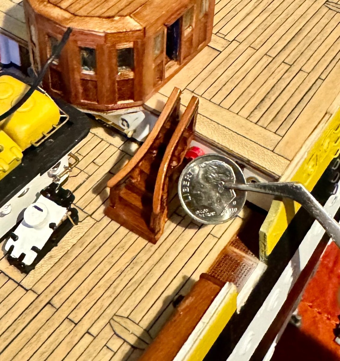
Happy New Year mates. Today I spent some time completing my first of four wood grand staircases that go between the mid deck and the fore/aft decks. I think my fingers are too big for these small parts! Size comparison is with a U.S. dime.


-
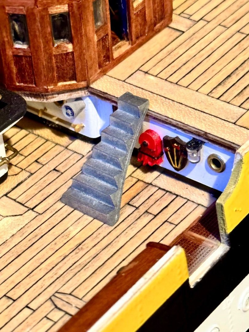
Another update has to do with the wood staircase between the different decks. The first image is the metal part supplied in the OcCre kit. I have been thinking for weeks how I would make this complex staircase look like wood. This is my first attempt and I think it came out well so I will do the other three staircases the same. I could have painted the steps brown, or attempted to make a paint pattern that looks like wood, but what I decided to do is laminate the metal part with very thin lime wood and then stain and varnish to look like the rest of the wood on the model.
-
Good evening mates and a Happy New Year! Today’s update is the completion and permanent installation of another hatch. Only two more hatches to make on the mid ship.

-
Good evening mates, here is a simple hatch update. Another departure from the OcCre plans, but a nice set of hatches.
-
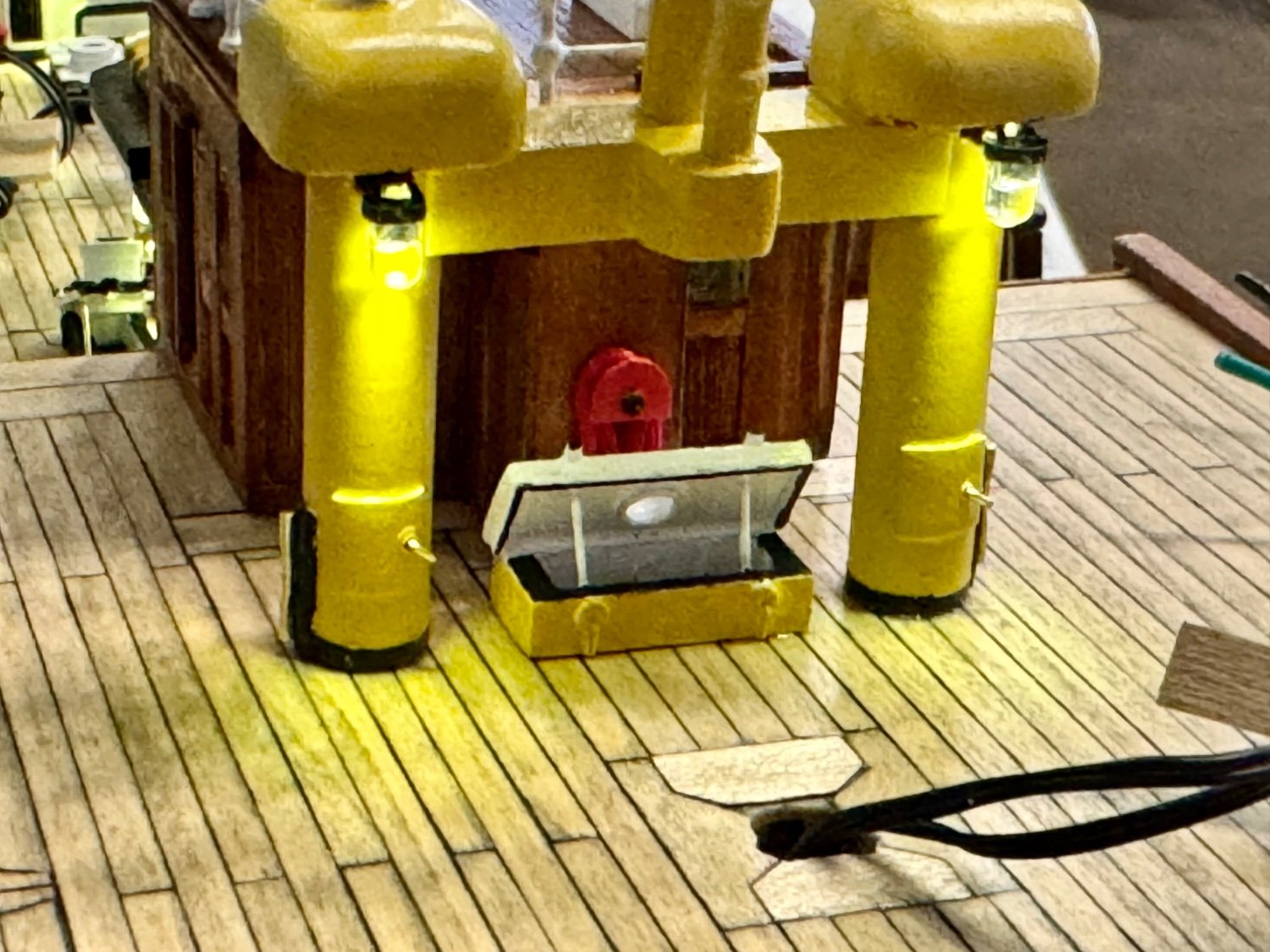
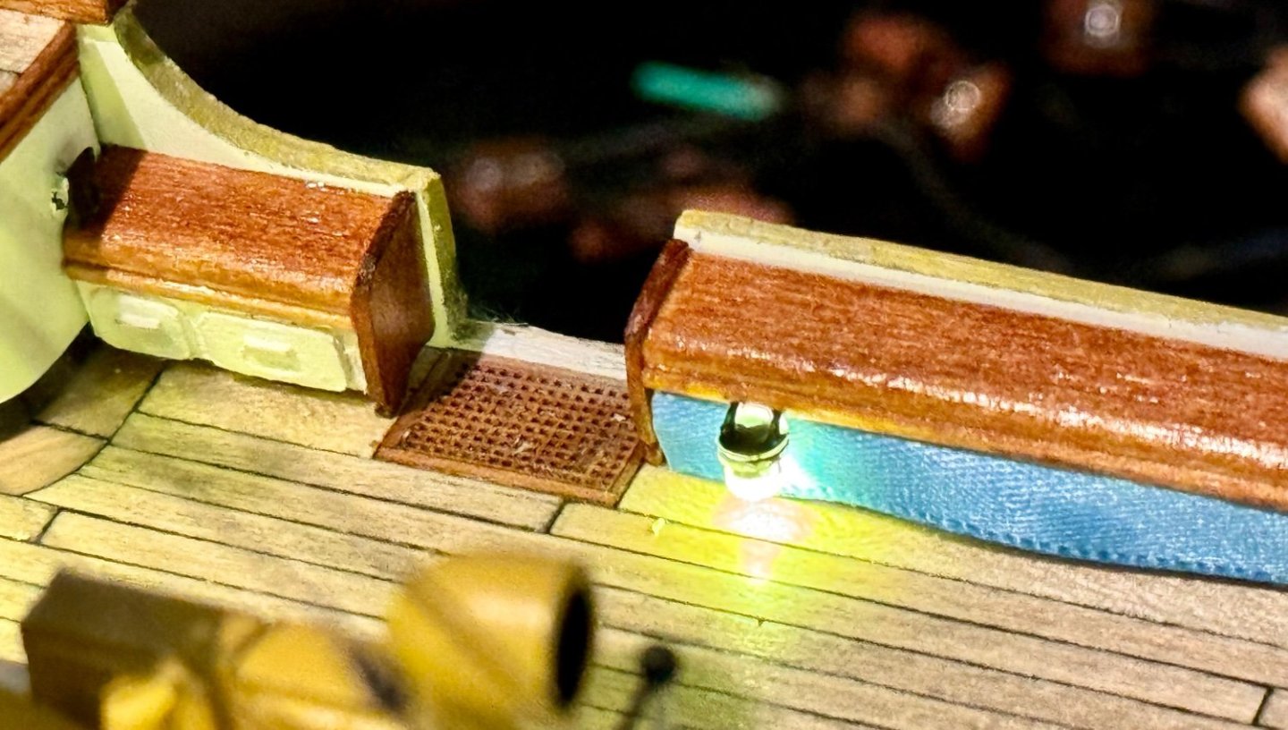
Question for the more experienced ship builder. In my previous post I manufactured a “toolbox” that is covered by a blue canvas. My question is how can I stick the blue fabric down to the frame without losing the look of it being fabric? I can’t use glue as it soaks into the fabric and alters the color. Double sticky tape would work, but it dries out over time and becomes ineffective. Is there a process or product that acts like double sticky tape but lasts, well…forever?
-
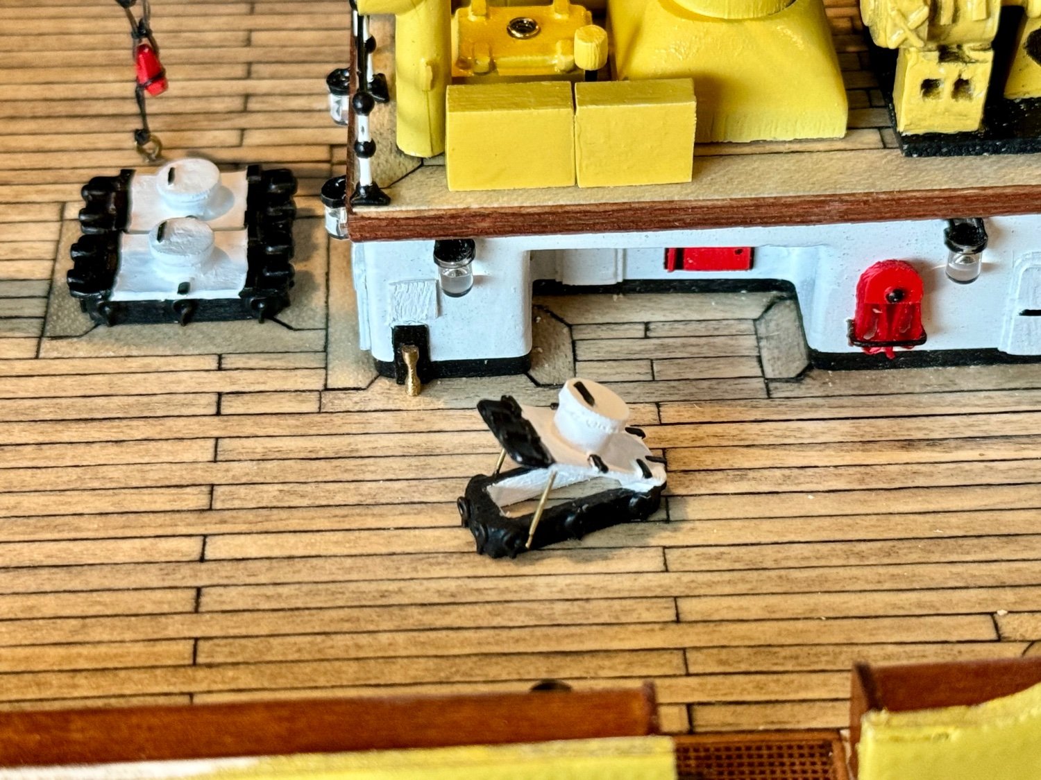
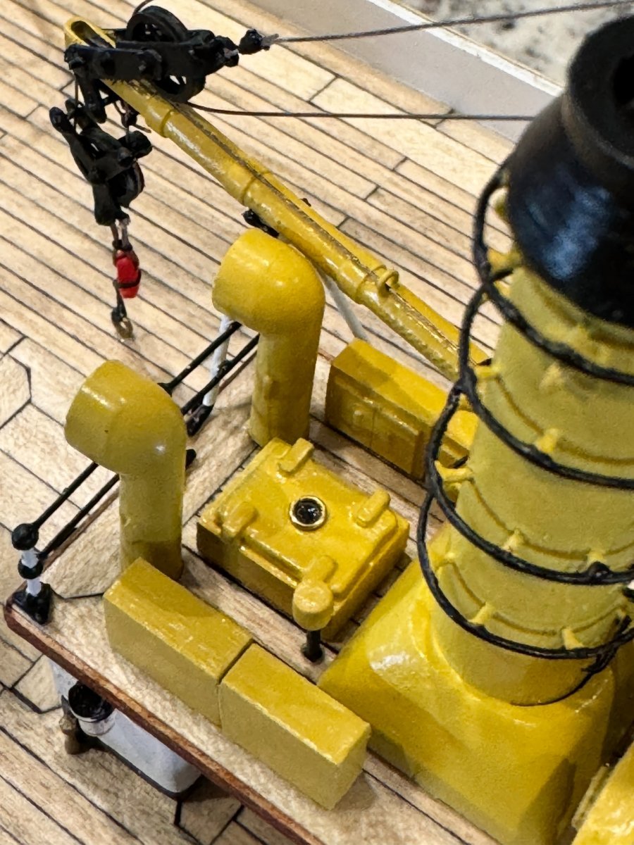
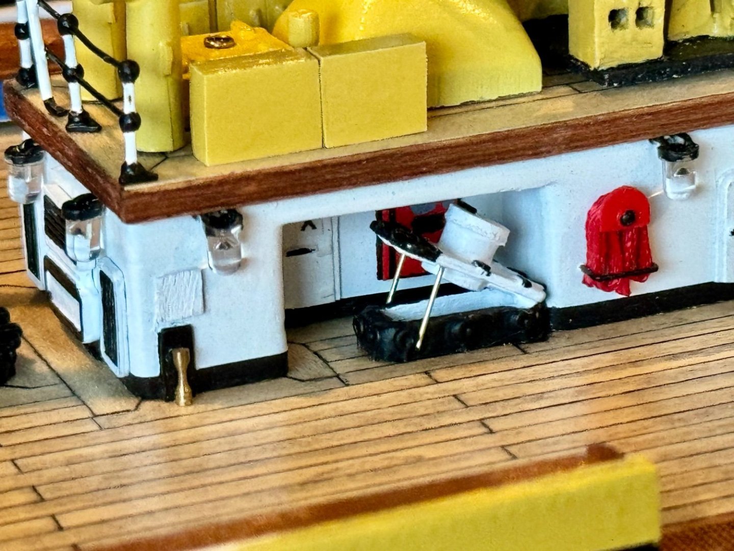
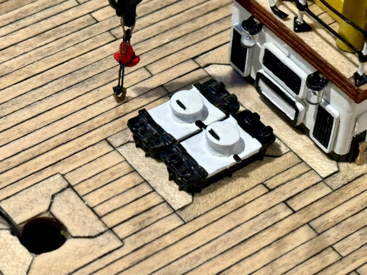
Well mates, not often I update twice in one day, but a significant part was completed today. One that I’ve been putting off as I was not sure how to manufacture them. Not sure what these are called, but on the AV they line the midship gunwale. These “toolboxes” appear to hold ropes and tools needed on the main deck and have a blue canvas/cloth cover to keep the water out and the deck looking clean. And in the case of the AV, have lighting.

-
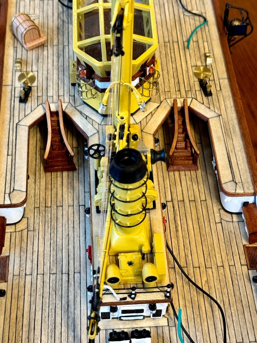
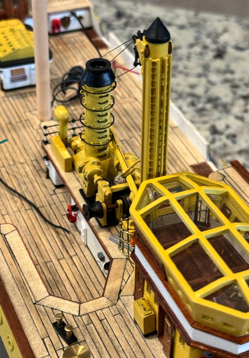
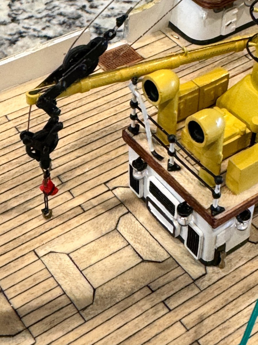
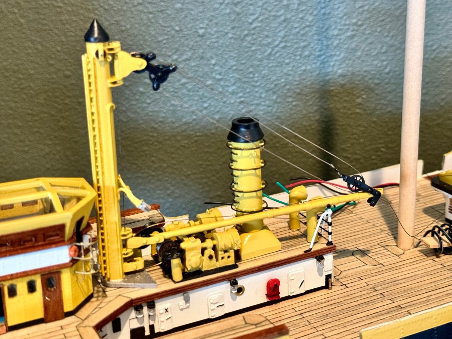
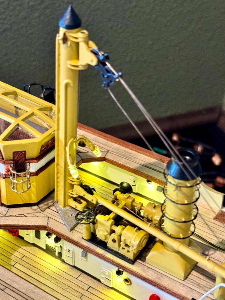
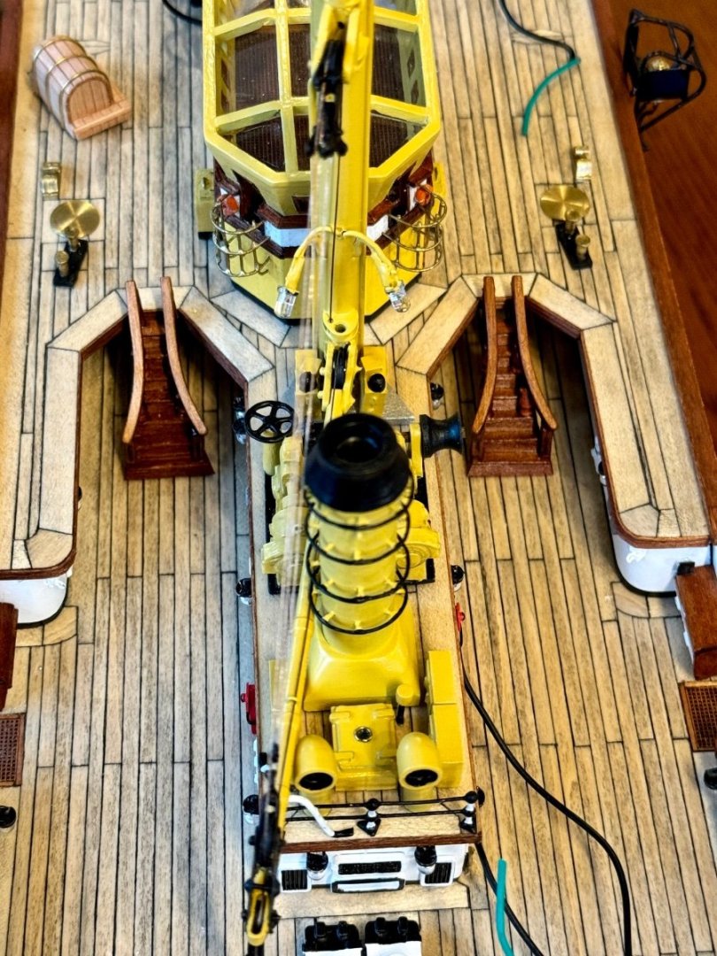
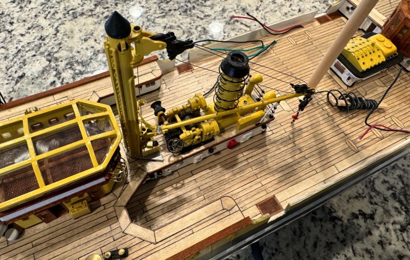
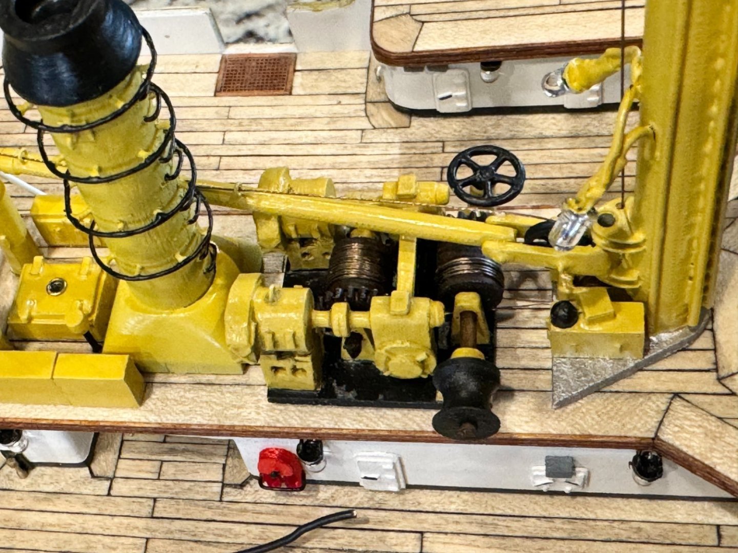
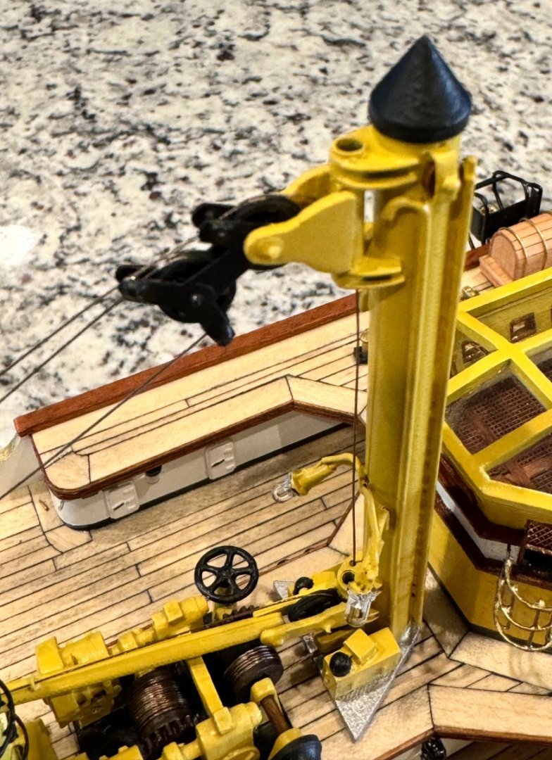
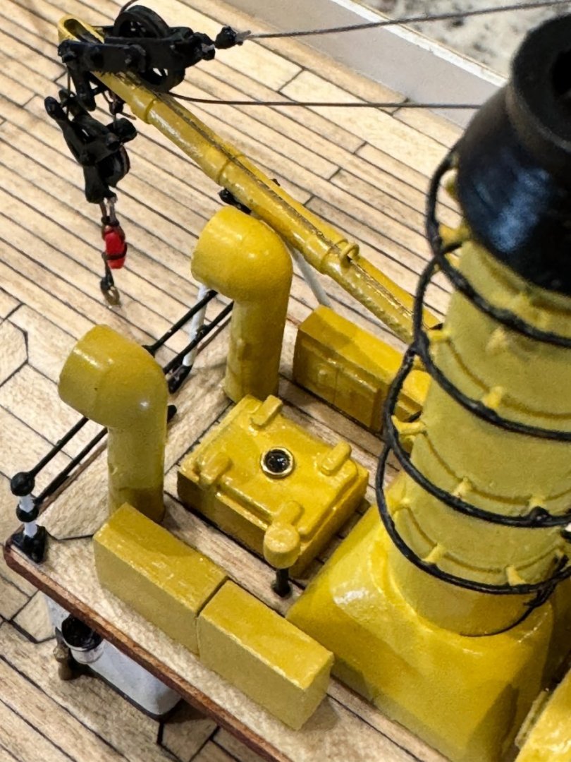
Good morning mates, it has been awhile since my last update, so...here it is. I have finally finished the aft section of the upper fore deck with all its motors, derrick, lines, and tool boxes. These parts are a huge departure from the kit and built much more like how the Amerigo Vespucci looks today. Next...moving on to the equipment of the mid deck.


-
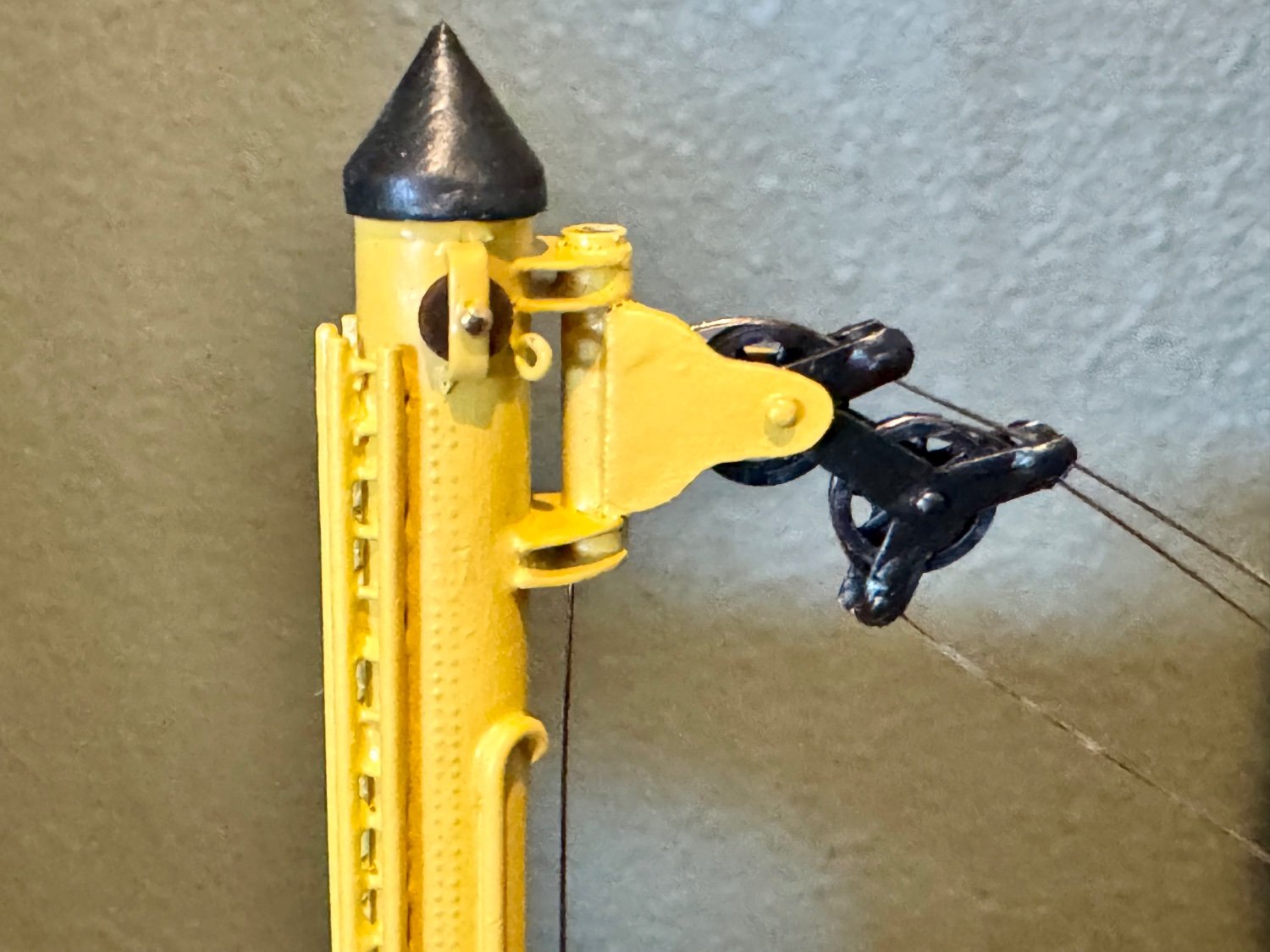
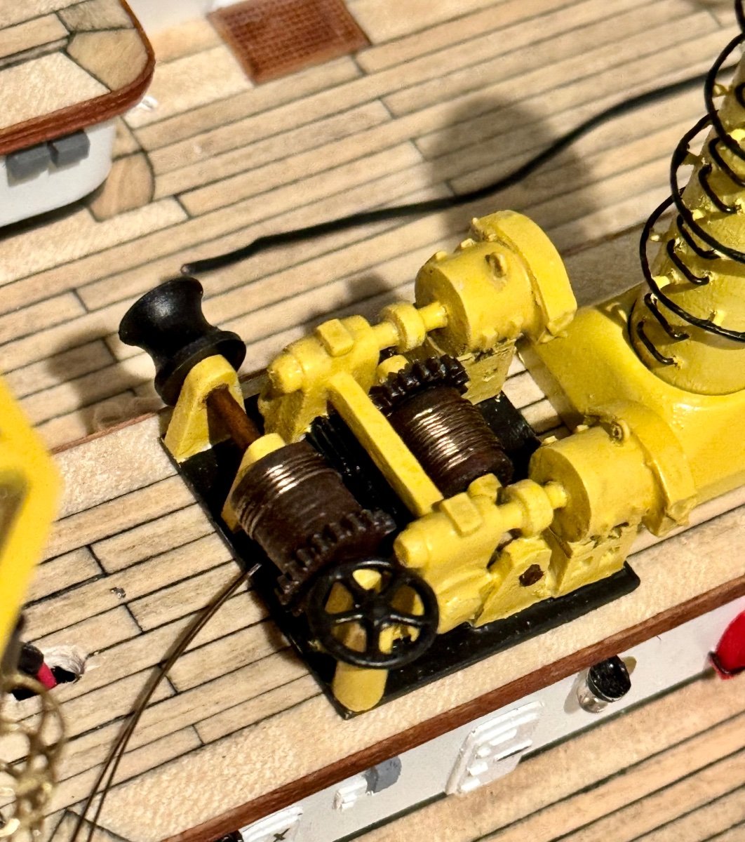
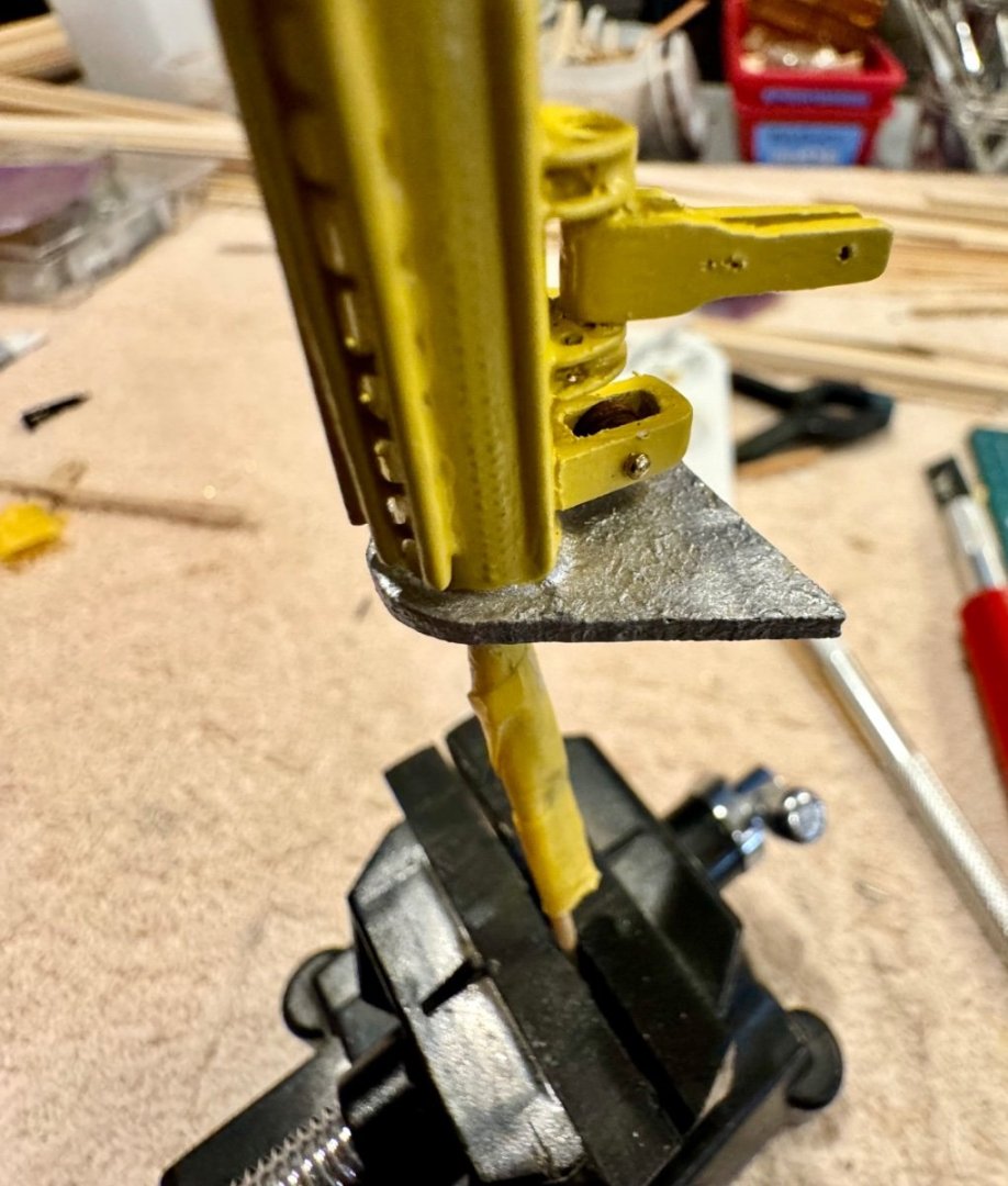
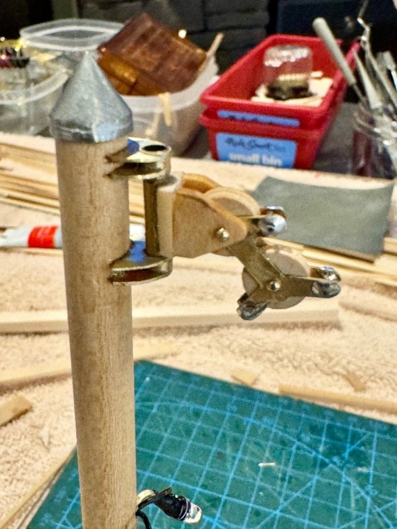
Good afternoon mates, more work on the derrick. Nearly finished with this part of the ship and ready for the next AV adventure. I think I’ve spent about a month working on this feature! Many thanks to Keith (clearway) for suggesting some railroad belt pulleys that I might be able to use on the derrick. I had to modify them a bit, but I think they look just right.


-
Ahoy, and welcome to MSW.
-
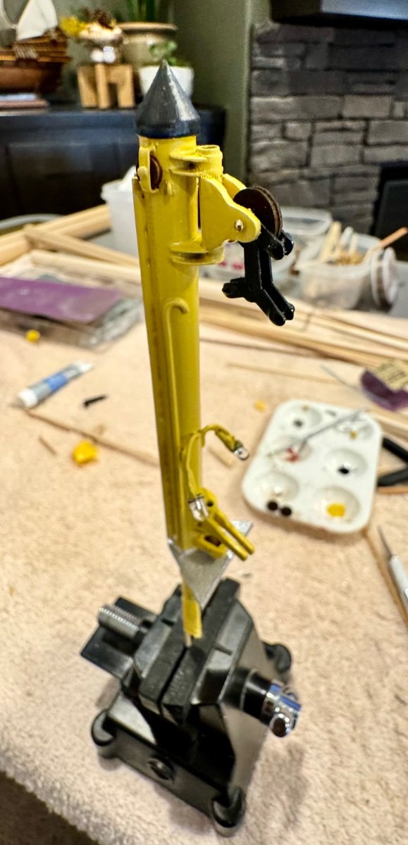
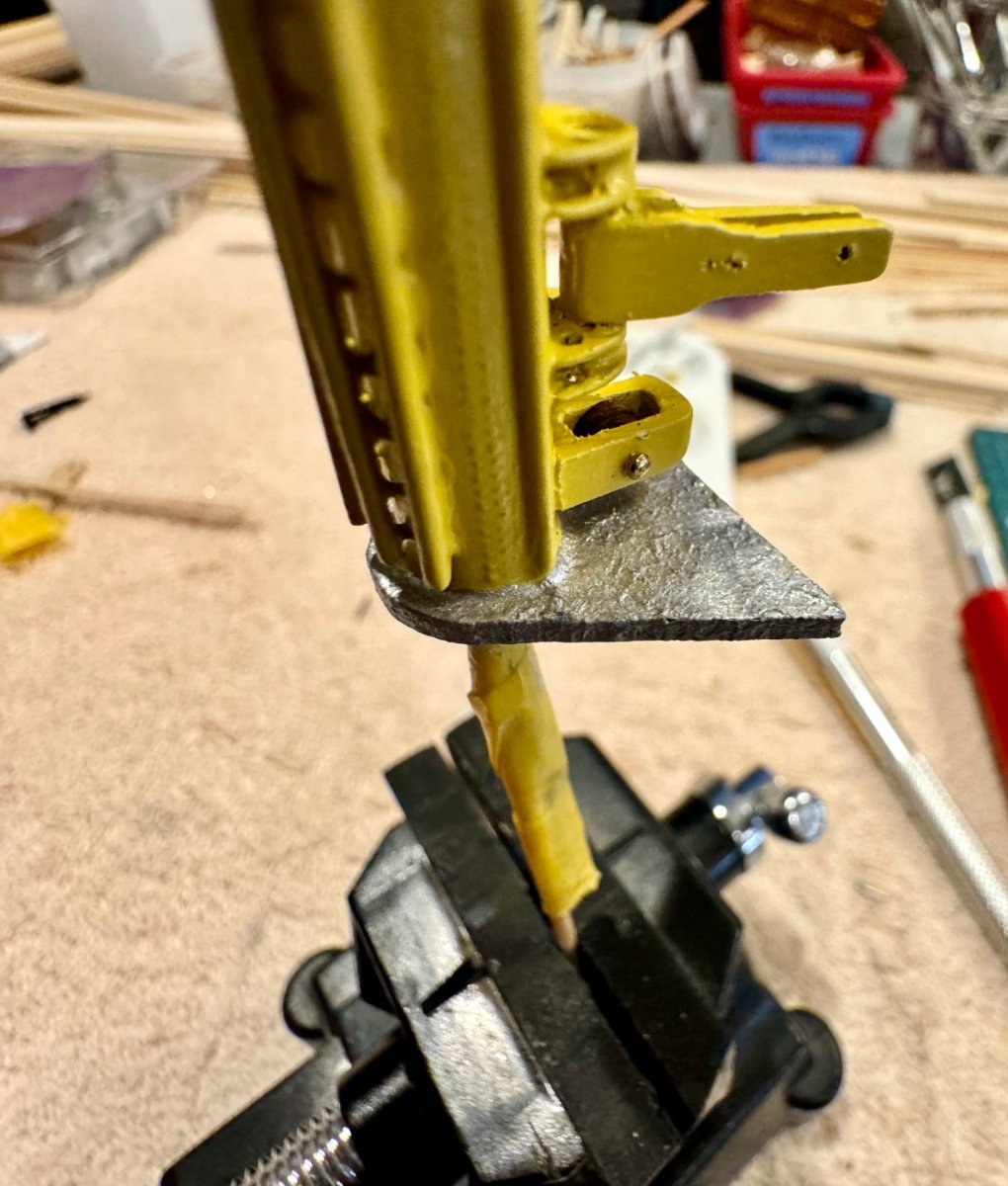
Good evening mates, time for a weekend update. I’ve continued to work on the main derrick with completing the motor sled and nearly have the derrick tower completed. Almost ready for permanent installation! This is my first time I’ve attempted a texture paint job. The base of the derrick tower on the real AV is covered with aluminum colored diamond plating. I’ve dabbed silver acrylic paint over the surface a couple of times with the hope of achieving something that resembles the rough texture of diamond plating.

-
I’ll look and see, I’m not happy with the pulleys but when I try to add the holes, the entire thing falls apart. I hadn’t thought about railroad pulleys. Good one and thanks!
-
Another update mates, more work on the mid ship derrick, building the equipment at the top. Below is a portion of an image I’m attempting to model after.
1.png.16f642d4162a8b25bfeb90f0d1168e18.png)
-
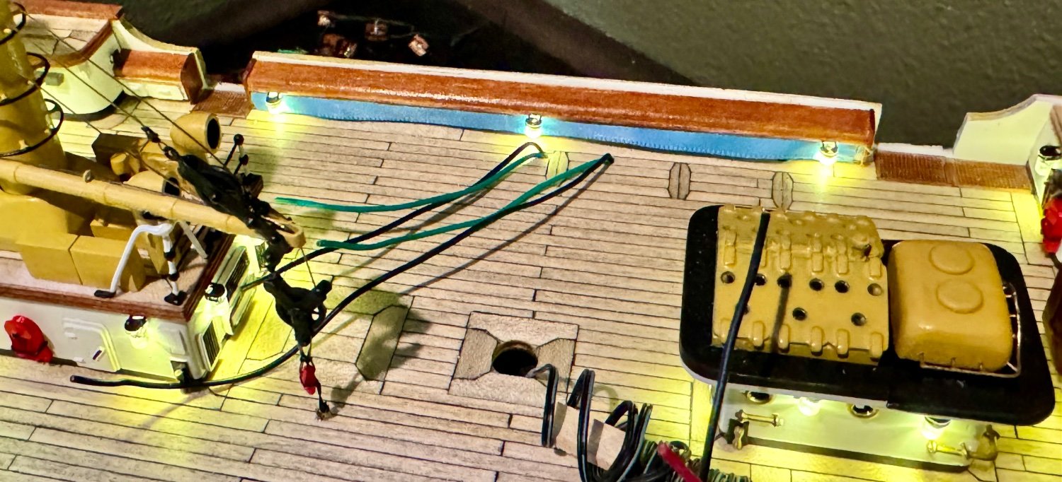
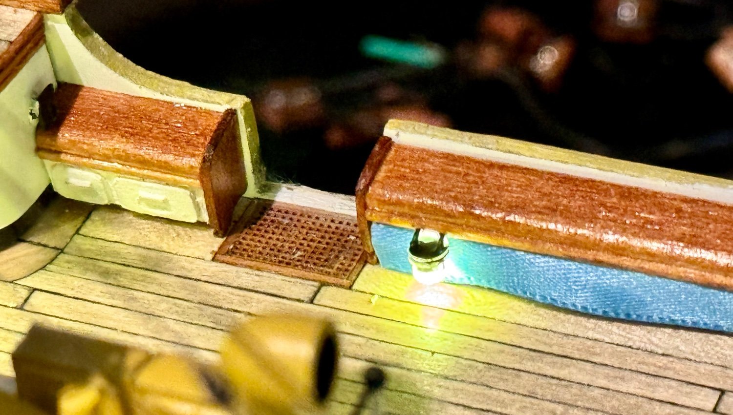
Good morning mates, well…its seems that the best laid plans need room for change. As I have been working on the mid ship crane/derrick, I discovered that there are two lights on it that are important for the lighting effect. Except that I didn’t plan for them in my initial design. After a little fishing and rewiring, I was able to get the derrick lights to work with the deck lights. Change is good, or so I’m told.