DanielD
-
Posts
653 -
Joined
-
Last visited
Content Type
Profiles
Forums
Gallery
Events
Everything posted by DanielD
-
 Yes, I planned my wiring layout with this in mind. There is another option, I just did not have the parts on hand. Currently you are using 1/4 watt resisters as they are very small and easy to hide. To run 4-6 LEDs on the same circuit off a single resister you can use 1/2 watt resistor of the same value. These resistors slightly larger but would still easily find inside the hull but are able to handle more current without over heating.
 -
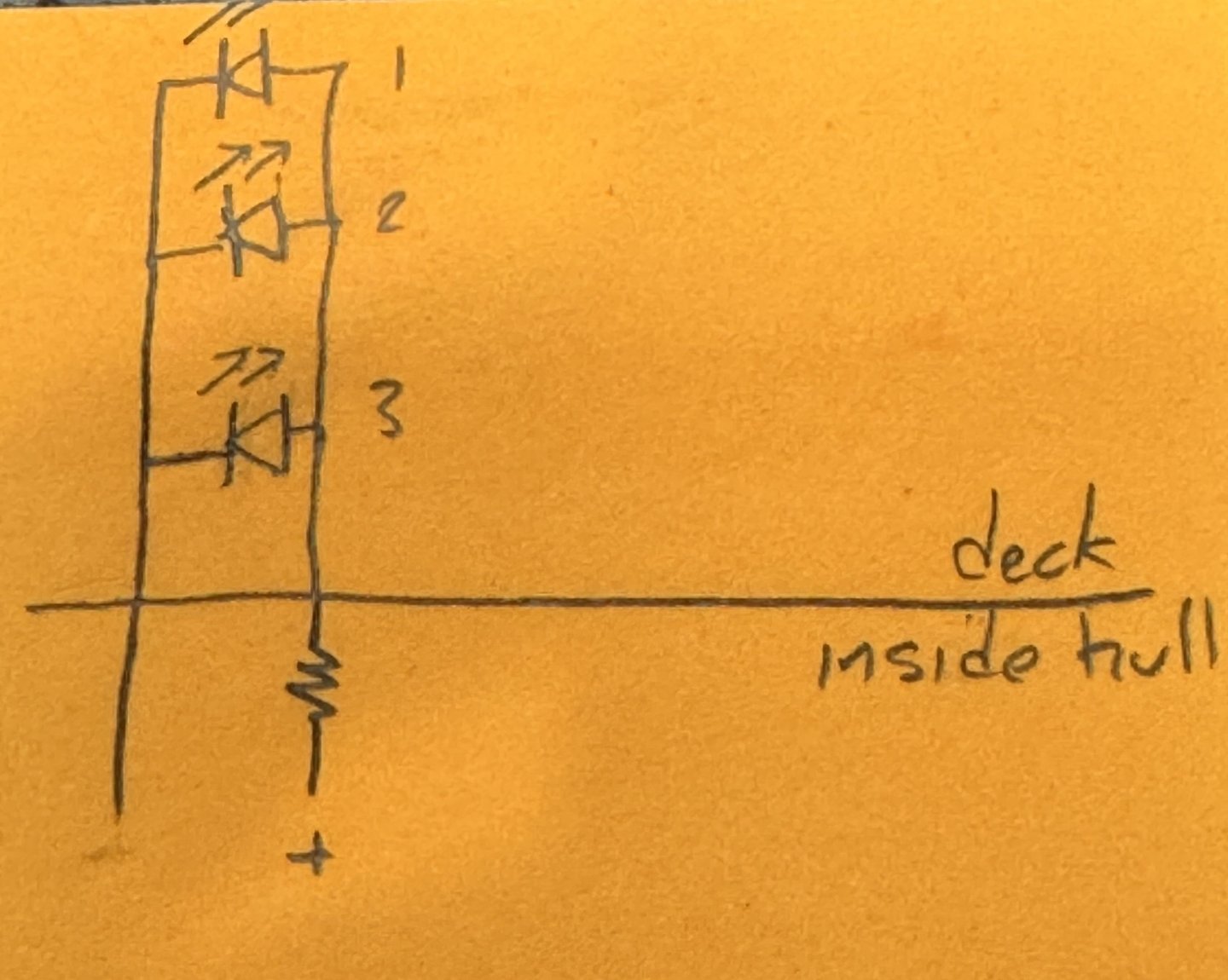
Hi Bill, sometimes electronics can be fudged a little, resisters are not precise, voltage drops are not always consistent, etc. Below is a circuit that fudges a little but works great, with one side effect, you will have to turn up the voltage a little to get the brightness you desire. Not too much, and no where close to overload the resister. So, I placed a resister inside the hull on a positive lead, the other side of the resister goes a max of three LEDs while the negative lead goes to the negative side of the same LEDs. This circuit is called parallel, which means that if one LED goes out (unlikely) the others are still connected and work fine. I used 3mm high intensity LEDs for this circuit, 3 LEDs for one resistor. This allowed me to make very small boxes to house the LED as each box only holds just the LED (no resistor). Hope this helps.
-
Bill, I have managed to add a wire or dowel to the bottom of most everything so that the parts stick into the deck. The flat pieces, if I could I soldered a pin to the bottom so that it would still fit into a hole. Some smaller things are glued in, but most everything can still be removed at this point.
-
I have not had the nerve to glue any of the deck equipment down yet. I made everything set in custom hole placement with conical shaped dowels so the pieces fit snugly on the deck and don’t move. My plan is to eventually glue it all down (or not) incase I need to get under them for some reason.
-
Bill, yes, I added these lights after I did all the initial planing and wiring and after closing up the hull. My mistake for sure as I believe them to be very beneficial to the deck lighting. Oh well, it was an easy fix. I drilled the upright dowels out to accommodate the wires for the new LEDs. Then added a hole in the deck under the uprights. Still to this day I have not glued down my bridge building as it’s just stuck to the deck with 3 or 4 dowel pins, so I just fished a wire through the new holes up into the floor under the bridge. Made the connections to the bridge wires, pushed them back inside the hull, and connected the new LEDs. When the bridge lights come on, in my case along with the deck lights, so do the new LEDs in that structure. I hope this helps.
-
Good afternoon mates, it’s been some time since my last update. Progress on my AV has been slow as I’m learning how to make furled sails. I have completed the sails at the bow. Now on to the fore mast sails.


-
Hi Bill, visual progress is slow for me right now as I’m doing the rigging for the bow. I’m learning how to do furled sails so have a bit of a leaning curve to overcome. I’m also having to “make my own sails” again as the ones supplied in the kit are way too thick to fold up without looking out of place. I’m using tea bag paper, very thin but ultra strong, then make the sail stitching to simulate panels, then stain the sail so it doesn’t look too white, then sew in the rope the runs around the entire sale which allows me to have attachment points for the rigging. Also, each end point that secures to a pin in a normal ship has the special AV storage at the base of each mast, so I planned for all that and it’s tedious work getting the lines tied correctly. I have a few more lines to go to finish the bow sails, so I’ll add a new photo soon.
-
Bill, sadly I’ve done something similar with my HMS Terror. At that time I placed the wiring right under the deck, which when I drilled a hole for some piece of deck equipment, I severed a wire. I had to do micro surgery by taking out a deck plank and add a hole through the false deck, find the broken wire and solder it back together and repair the deck. It was a pain to say the least. Now I don’t put the wires directly under the deck to prevent future accidents. I guess we just learn from our past and move on.
-
The way I accomplished this exact problem is making the hole in the brass the exact diameter of the body of the LED. Slide the LED from the bottom to rest on the lip and affix in place. No need to worry about the leads touching the Mount. Then I painted the bottom of the Led, the underside of the Mount, the same black as the Mount and it becomes invisible.
-
I made mine a single unit, so no lower supports attach to the hull. Easier to remove to work on shrouds, and I doubt anyone will ever notice.
-
Hi Bill, if I did it again I would do it differently. I soldered about 1” of flat 3mm bar in two places on the back side of the bracket, and then cut two slots into the side of the hull. This more or less made the entire device removable, so I could work behind it, then reinstall. Worked great, except cutting the flat slots into the hull was difficult. Instead, I’d I were you, I would use brass rod, maybe 1mm diameter, and affix to the back of the bracket. Then all you have to do is drill matching holes into the hull and slide in place. Still removable, but much easier construction.
-
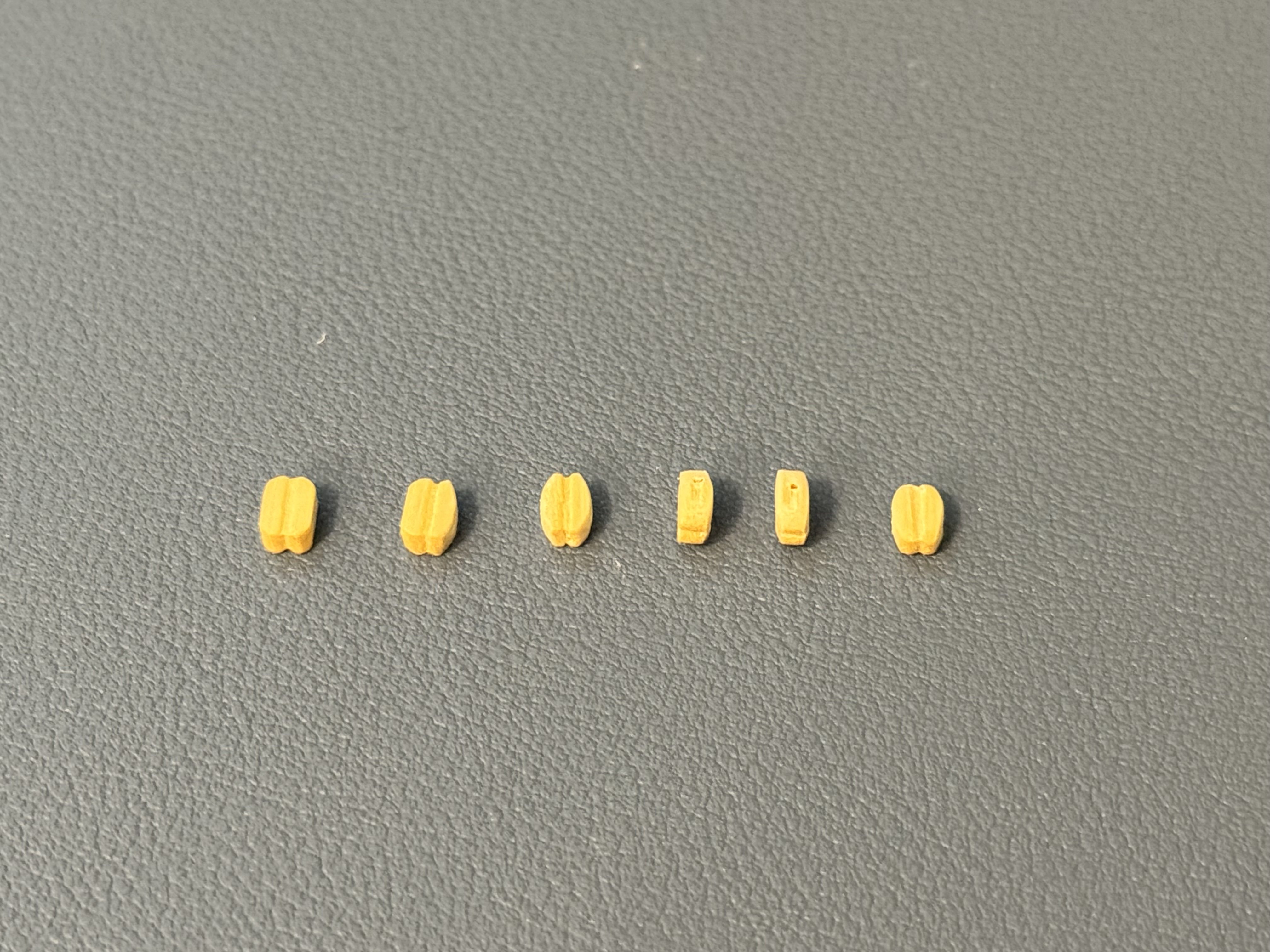
Bill, I know I’ma day late, but here is the progression of what I change on the include blocks to make them more realistic.

-
Bill, I found absolutely nothing listed for the AV in the area of rigging. As such, I chose 3 sizes each for black and light tan. When I first bough the lines I’m using I was able to get here in the US. When I realized I didn’t have enough, I had to obtain more from China which took about a month to arrive. So…not likely a good resource anymore. The lines I am using are lightly pre-waxed so no “fuzz” and work well, just current availability is non-existent. As for the blocks, I used the ones that came in the kit but I’m modifying them to be more realistic. Hard to put into words, but I’ll try. Holding the block in a pair of needle nose pliers, sand the corners off the top and bottom creating a curved edge. Flip 180 degrees and repeat. Next grab the block with the pliers along the edges just sanded, 90 degrees from the initial sanding, and sand off the corners again. Flip 180 degrees and repeat. This rounds out the block in two plains, to make it much more realistic. Lastly, I use a triangular file and redo the grooves, top, bottom and both sides. When I get home I’ll upload an image of a before and after. It’s quite the transformation for about a minute of work.
-
Bill, there is nothing that says the resistor has to be next to the LED, meaning, the resistor can be inside the hull and a wire from one end of the resistor goes to the LED. In my setup, I ran a series scenario with the LEDs, meaning one resistor then the LEDs are run one after the other in series. This type of wiring does have a draw back, for the same reason Christmas lights are wired in parallel now days, if one bulb goes out, they all do. That aside, the resistor is inside the hull making for less hardware in the box.
-
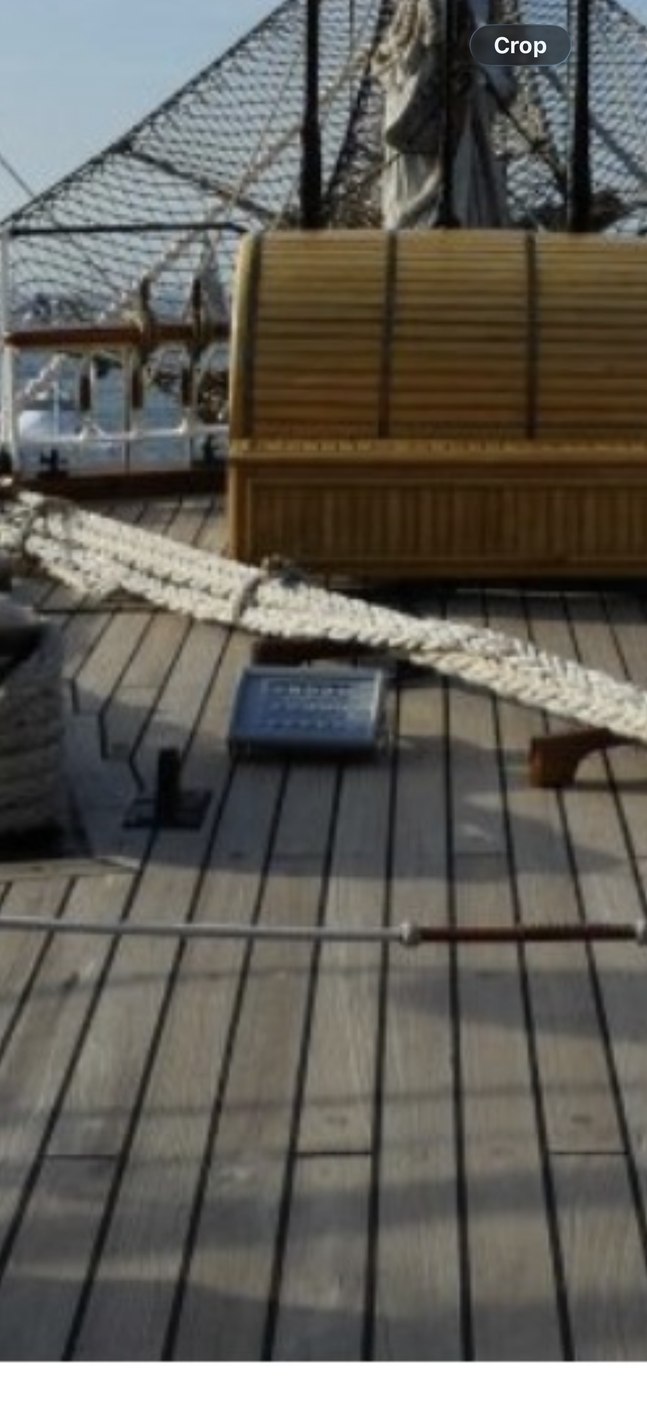
Hi Bill, the light boxes you see on my build are hand made in an attempt to simulate the light boxes aboard the AV. Here is an image of one as an example. Of course in scale it’s not possible, so I have installed a single 3mm high intensity LED into each hand made box.

-
Bill, nothing much you can do now. My next build I will paint the inside of the hull and the underside of the deck black, then an off white so that the light will reflect around eventually coming out the port holes. The light layer will reflect most of the light, but what leaks through the black layer will absorb the light so it can’t get through to the deck, etc. turning down the intensity of the LEDs didn’t make any improvement in my case.
-
Bill, something I’ve learned through life…the admiral is always right! Nicely done!
-
Hi Bill. Yes, I drilled the port holes and installed the grommets before painting. I paint most things using my air brush so I have complete control of where paint goes. When I sprayed the colors, I sprayed at an angle, not directly into the port holes, so what little paint makes it through the opening is not directed at the midline LEDs. As for my choice in painting the grommets, the porthole frames, take a look at any image of the real AV and you will find that the porthole frames are painted the same as the surrounding hull. I also added, not included in the kit, the porthole rain gutters which were all affixed prior to painting. Hope this helps. Daniel
-
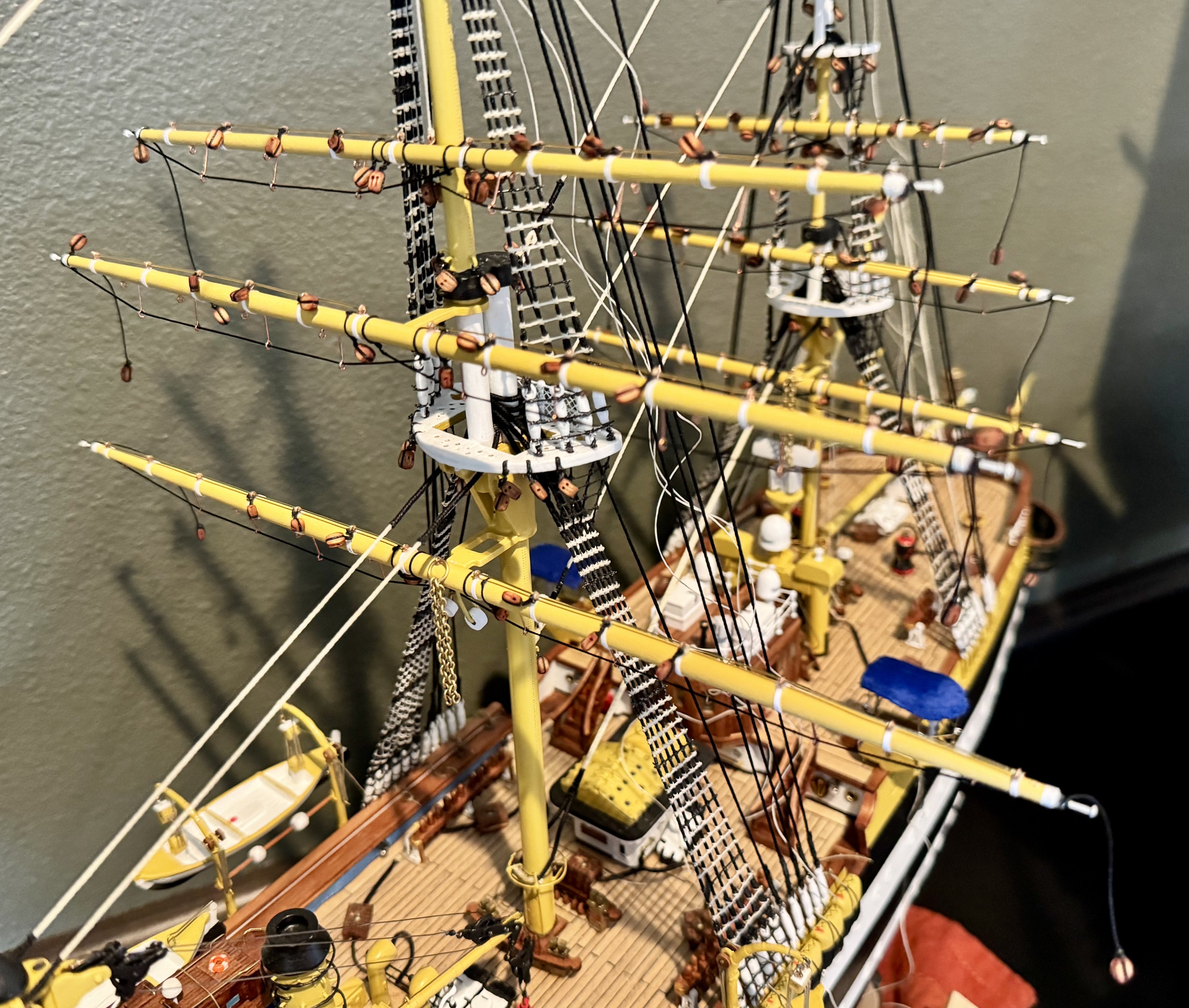
Good evening mates, today I met a milestone with my AV! I finally have all the yards completed with all the hardware (15 of them). Next up is to add the blocks to the standing rigging, then the furled sails…once I figure that out.

-
Yes, rubber cement. It’s a type of contact cement, put glue on both pieces, wait for it to dry, and press together (contact) for the adhesive to activate.
-
Hey Bill, I used Elmer’s Rubber Contact Cement. It is great, but it was hard to get the hang of using it so I think that is why some don’t like to use it. For me, I worked in small sections the length of the ship. Since the AV is a steel hull, there is no need to spend a ton of time making planks, so I used long plank sections from bow to stern. I started by drawing a line on the hull to place the first plank. Brush a thin coat of the cement on the back side of a couple planks and on the area along the hull for two or three planks. Let the glue dry! This is important! The glue will be dry to touch. Then carefully place a plank along the line that was drawn on the hull. Press the plank in place. Contact and pressure is what activates the glue, but it is permanent. You won’t be able to remove the plank without braking it into a bunch of pieces. Careful placement is critical! This is what makes it hard to use. However, once I got the hang of it, it was by far my favorite way to attach planks to the hull and I will use this technique on the next deck I do in the future. Again, once “pressed” in place, it’s immediately stuck and permanent and no wait time is needed between planks.
-
Hey Bill, it’s my turn to borrow an idea from you! I’ve been thinking how I might do my base for over a year, love what you have done!
-
Hi Bill, I tend to keep everything left over from each model. Sometimes I find a good use for the leftovers.
-
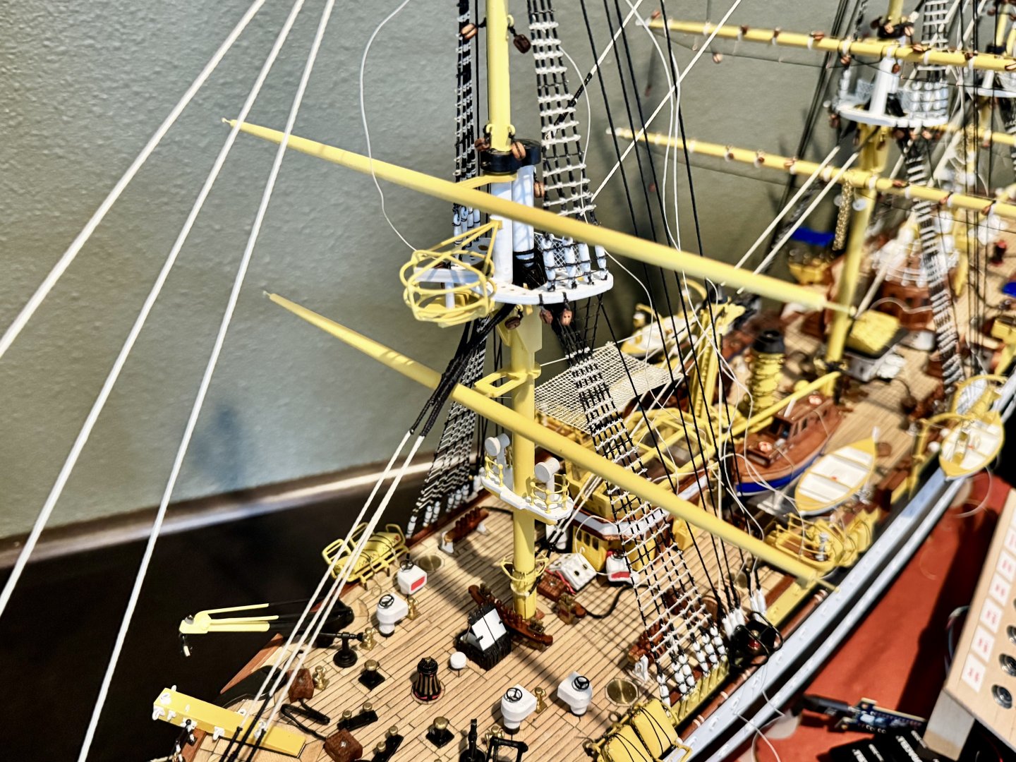
Good morning Bill. I swapped out the threads for pre-waxed thread. While the images here look like white, it’s actually light tan although the actual ship seems to be white and very dark almost black. A couple reasons for me switching to the lighter color lines is that I’m building this model primarily for the night time display that the AV is known for, the Italian flag. Using the lighter color lines will reflect the red, white and green up lights better giving a more impressive display. Using dark colors will absorb much the light causing a much duller display. Except for the pre-waxed lines, most of the rest is from the kit. Notable exceptions are 1) the real AV has metal bands at intervals on the yards. I simulated this by using a standard sheet of white paper and cutting 1mm strips. Glue them around the yards and I have the appearance of a white band that has some depth to it (see the images above). 2) I used smaller eye pins than what comes with the kit. I think the ones in the kit are 3mm in diameter while the ones I used are just under 2mm, 1/3 smaller than the kit provides. Using the ones in the kit are just way to big for the scale of the ship. Actually, so are the ones I used, but it’s much better scale wise.
-
Good afternoon mates, it’s been awhile since my last post, but progress has been steady. I’ve been working on the yards, a total of 15 on the Amerigo Vespucci. Below is a comparison from an unfinished yard to a finished one.