DONATION DRIVE - SUPPORT MSW - DO YOUR PART TO KEEP THIS GREAT FORUM GOING!
×


Mirabell61
-
Posts
7,410 -
Joined
-
Last visited
Content Type
Profiles
Forums
Gallery
Events
Everything posted by Mirabell61
-
 Richard and Popeye thank you both for your appreciative words Nils
 -
Thank you B.E. of course it differs (typewise) from the beautifull historic Swan Class you are doing, but one could say at least also a riveted younger Oldtimer, now also having its place in history Regards, Nils
-
Thank you John, I asume it is (or was) typical for the Flying P-Liners, for example the 4-mast barque Passat was bearing Initials "F.L." for Ferdinand Laeisz, but this had been specially reconstructed for the todays Museum ship Nils
-
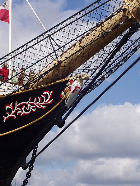
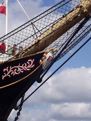
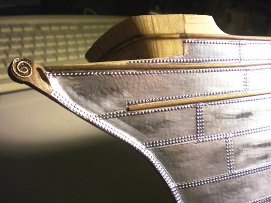
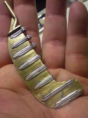
Does anybody know the english Name for that typical White bottle like decor on top of the bow post ?? In german we call it "krulle" During the owner periods the the Companies put their Initials or their Company logo on it. The last owner "Zerssen & Co" by using Z&Co is shown on my model Nils
-
David, you should see the smile on my face when I saw your lines, you also have a good senced Humor - Thanks mate- The bottle of beer Pops up before my very eyes, had a busy day out of house, will head straight for the fridge now... Nils
-
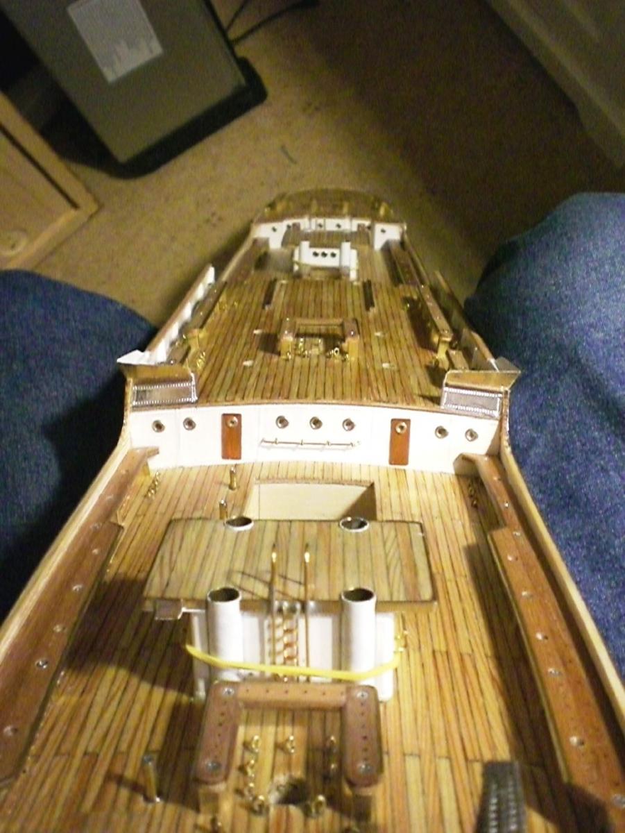
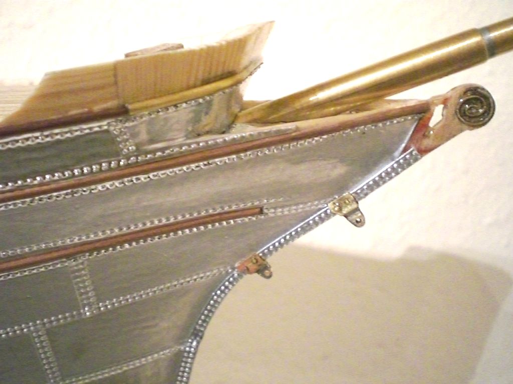
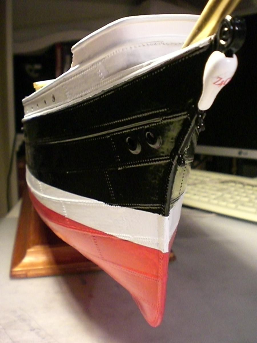
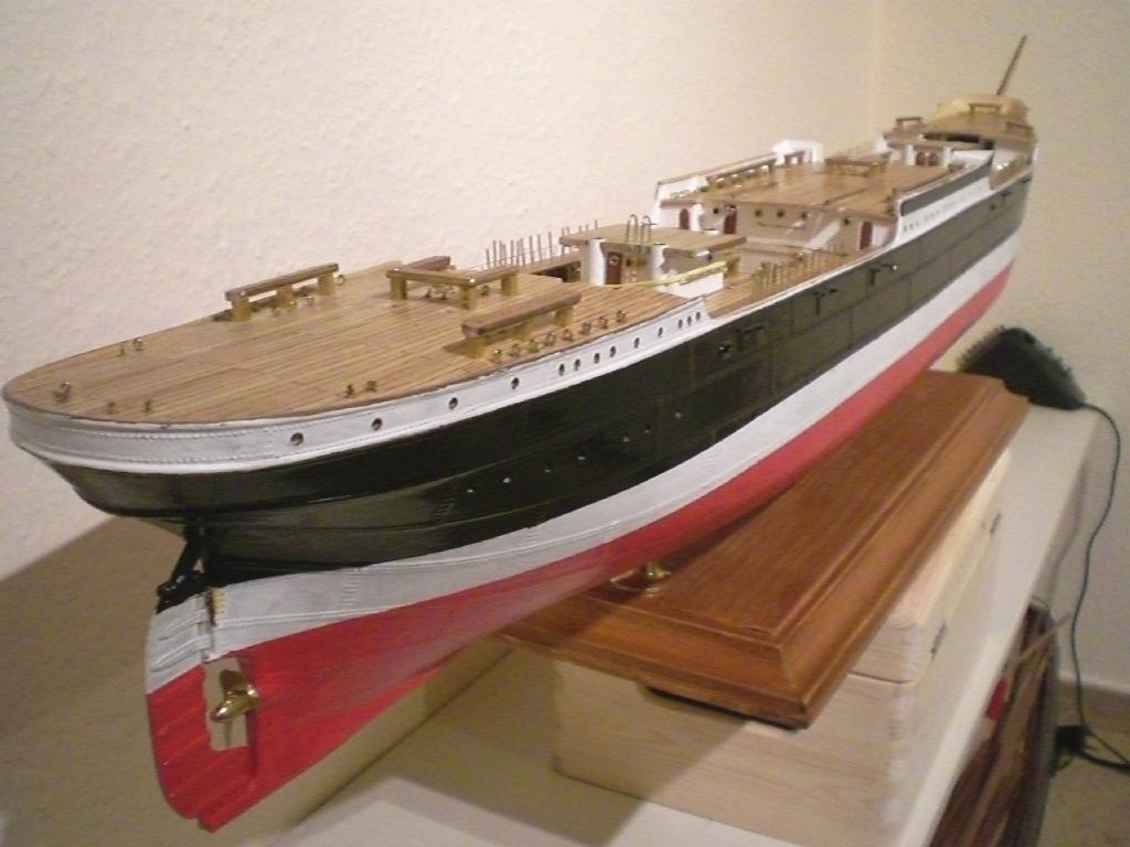
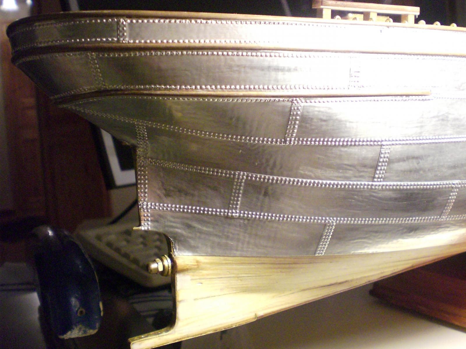
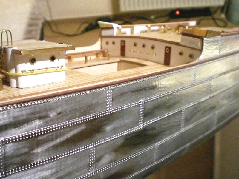
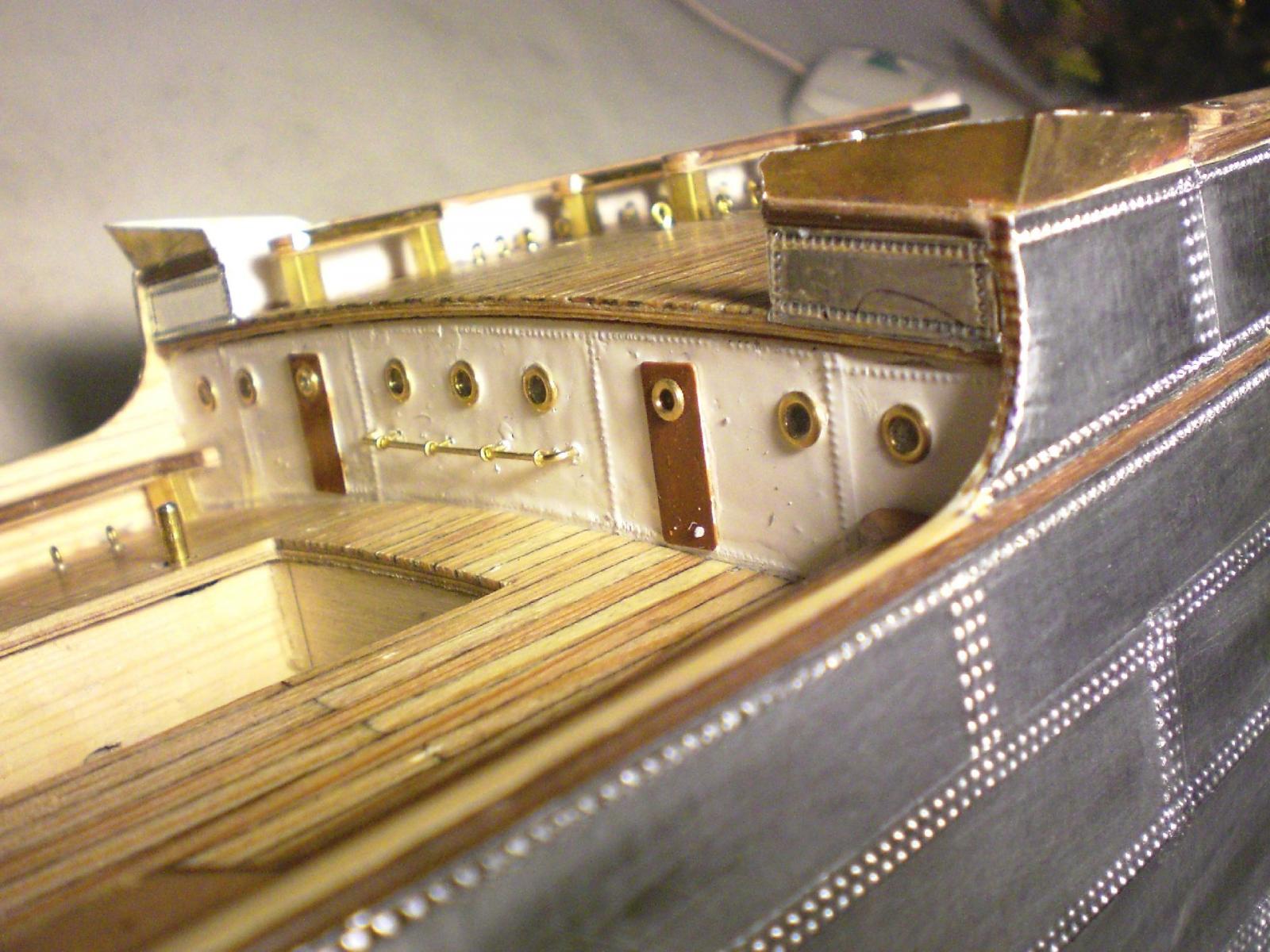
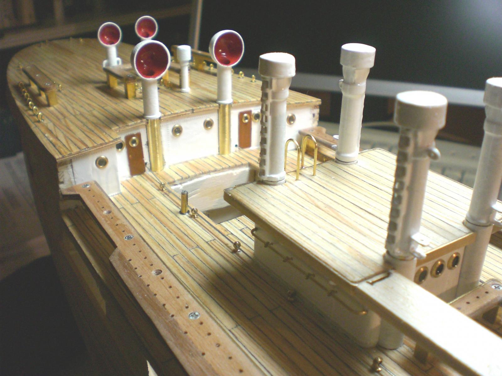
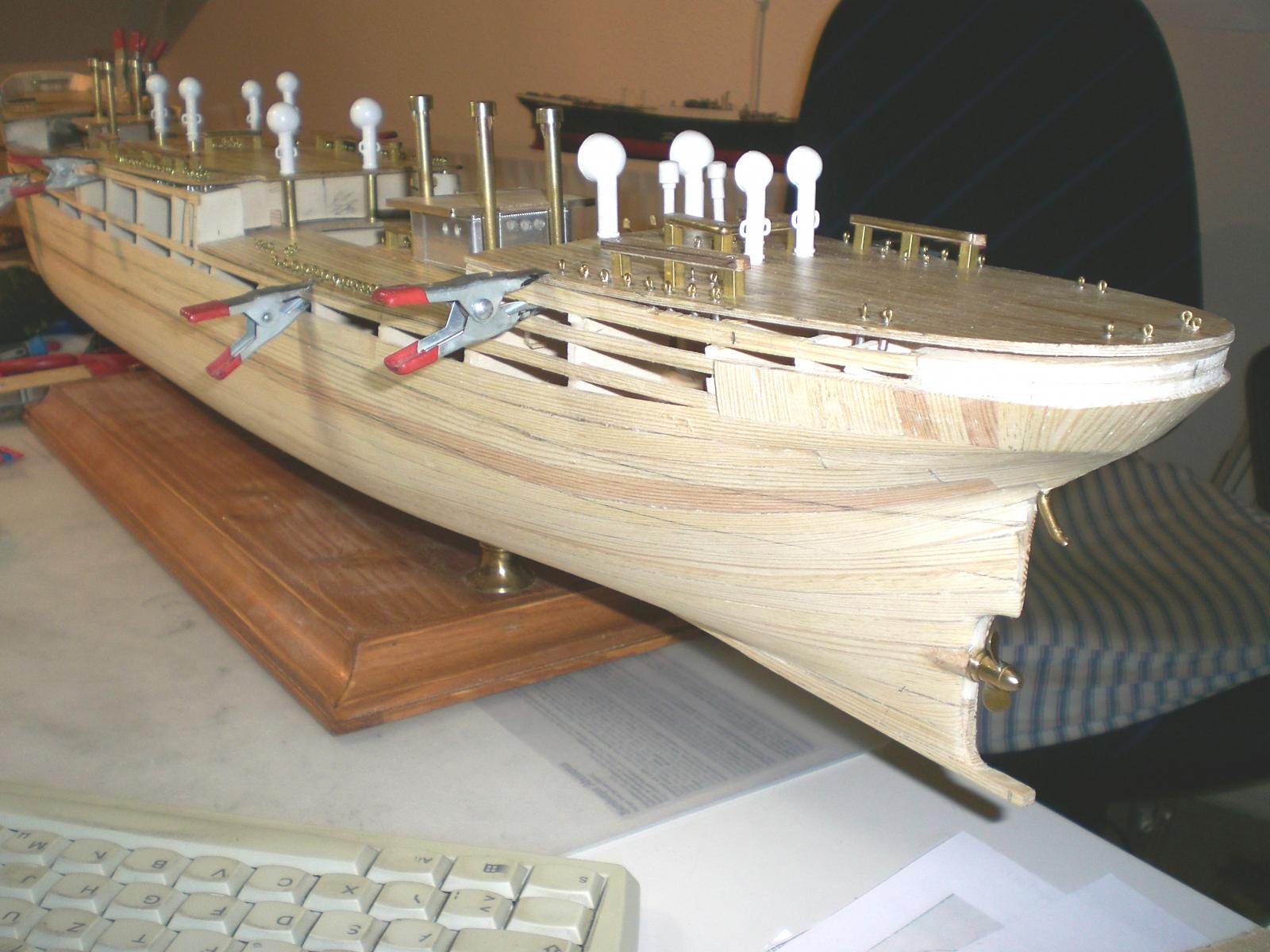
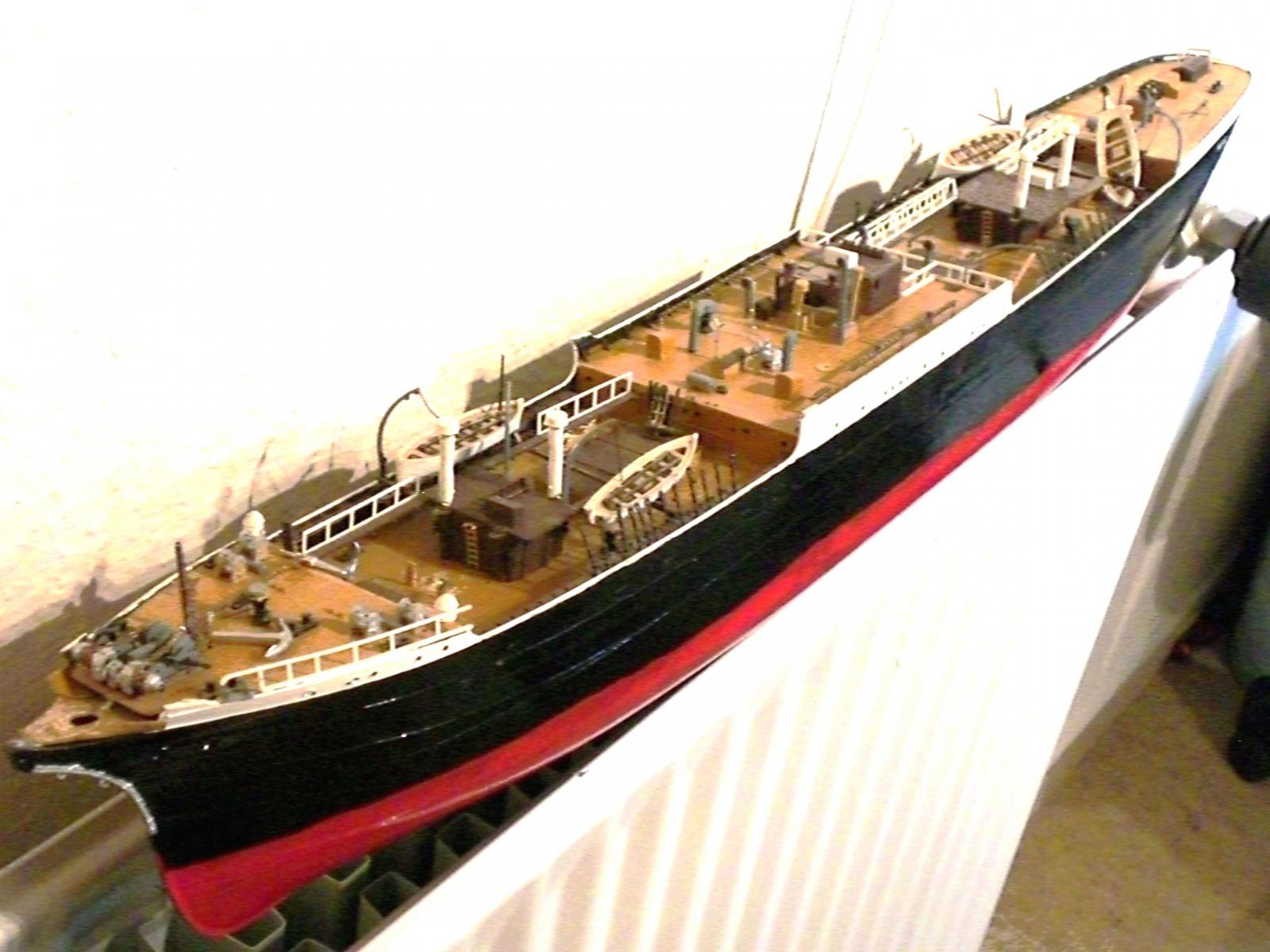
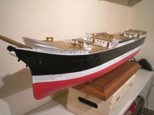
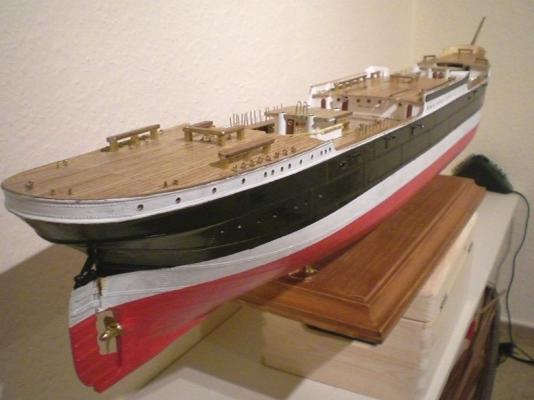
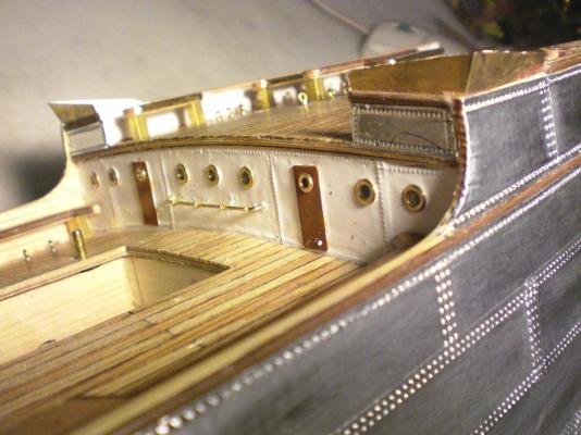
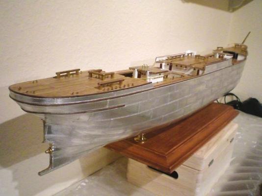
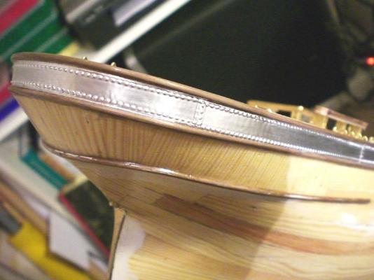
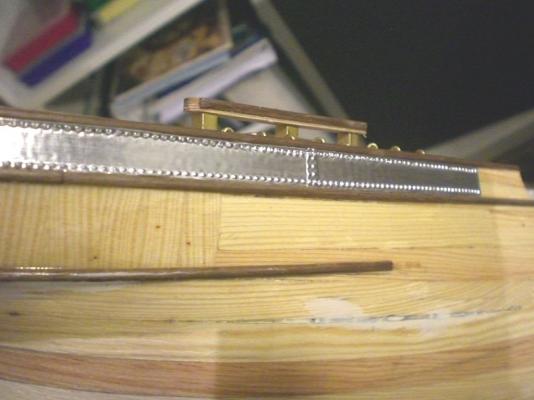
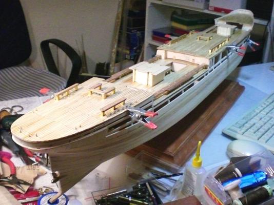
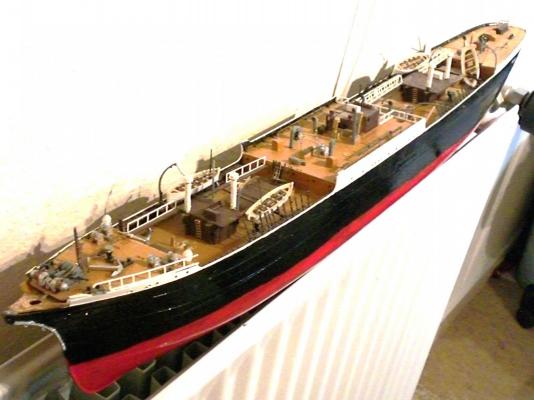
Build log part 13 plated right down to keel welldeck bulwarks mounted and plated highdeck wake protection spoilers Looks quite OK so far bow with fitted water stay fastening points the original Laeisz paint scheme finds its Revival here the anchor Points for shrouds and backstays are prolonged from welldeck upwards through the pinracks portholes not fitted yet have to get used to the new colours in my Hobby room so far, so good... Build log part 14 to follow.... Nils


- 269 replies
-
- 14
-

-
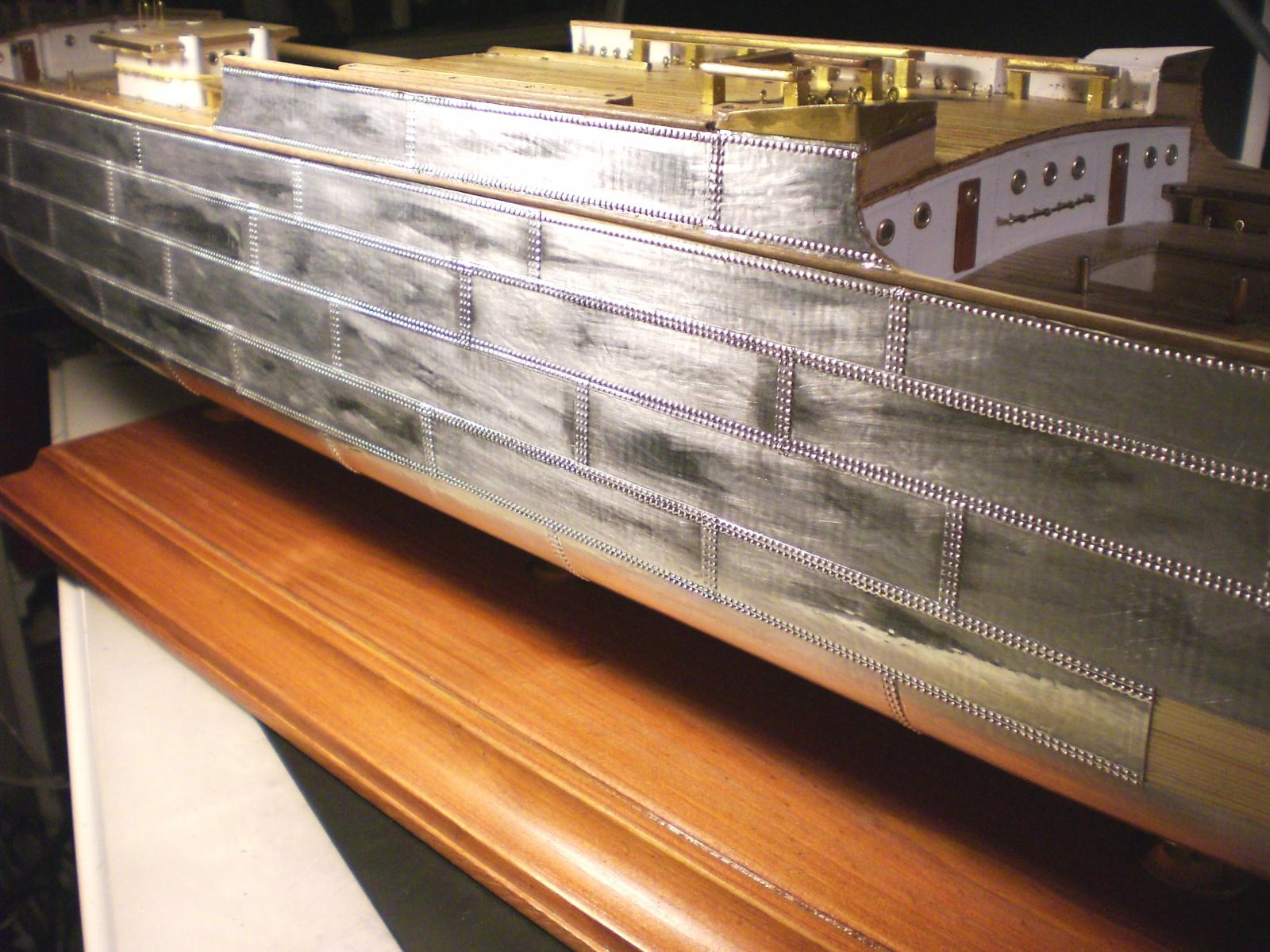
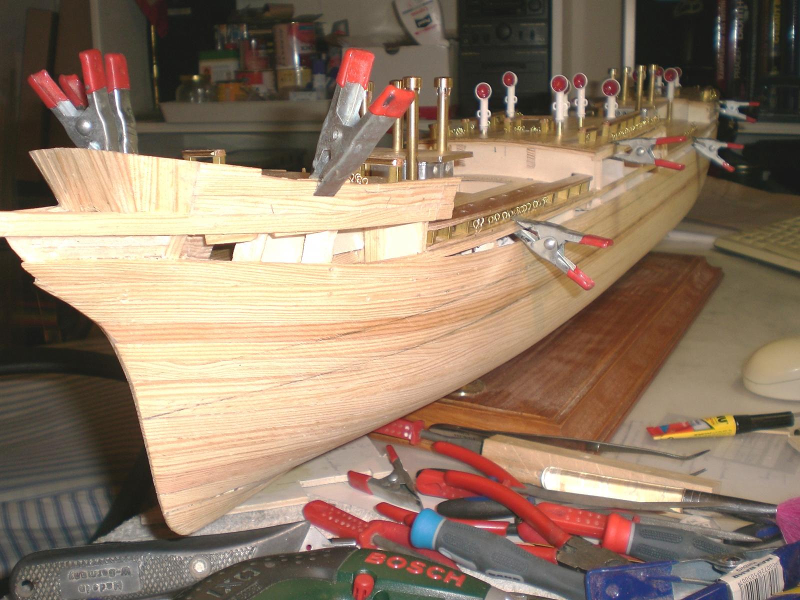
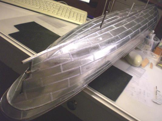
Build log part 12 Bulwarks on the high deck mounted and also plated Bow area plating for plating keel and bottom Areas the ship is removed from the stand and placed back on it again afterwards Build log part 13 to follow.... Nils


- 269 replies
-
- 15
-
-
Thank you John Nils
-
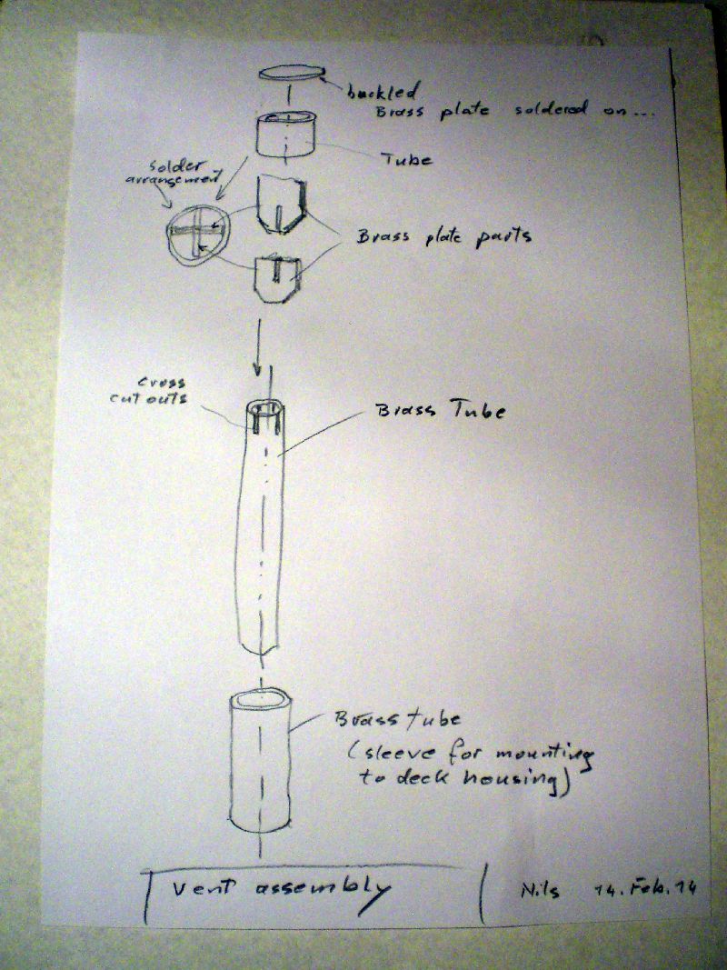
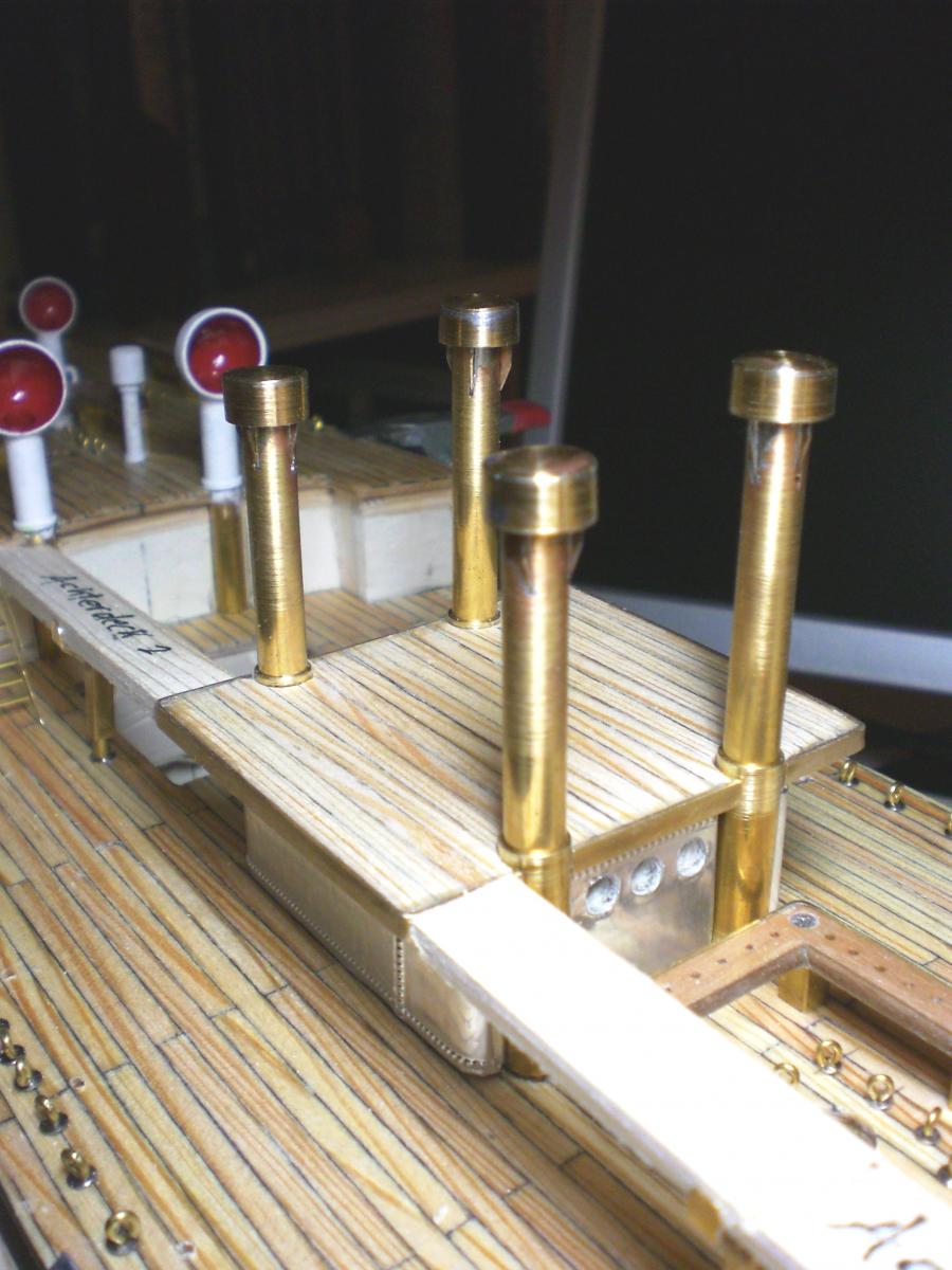
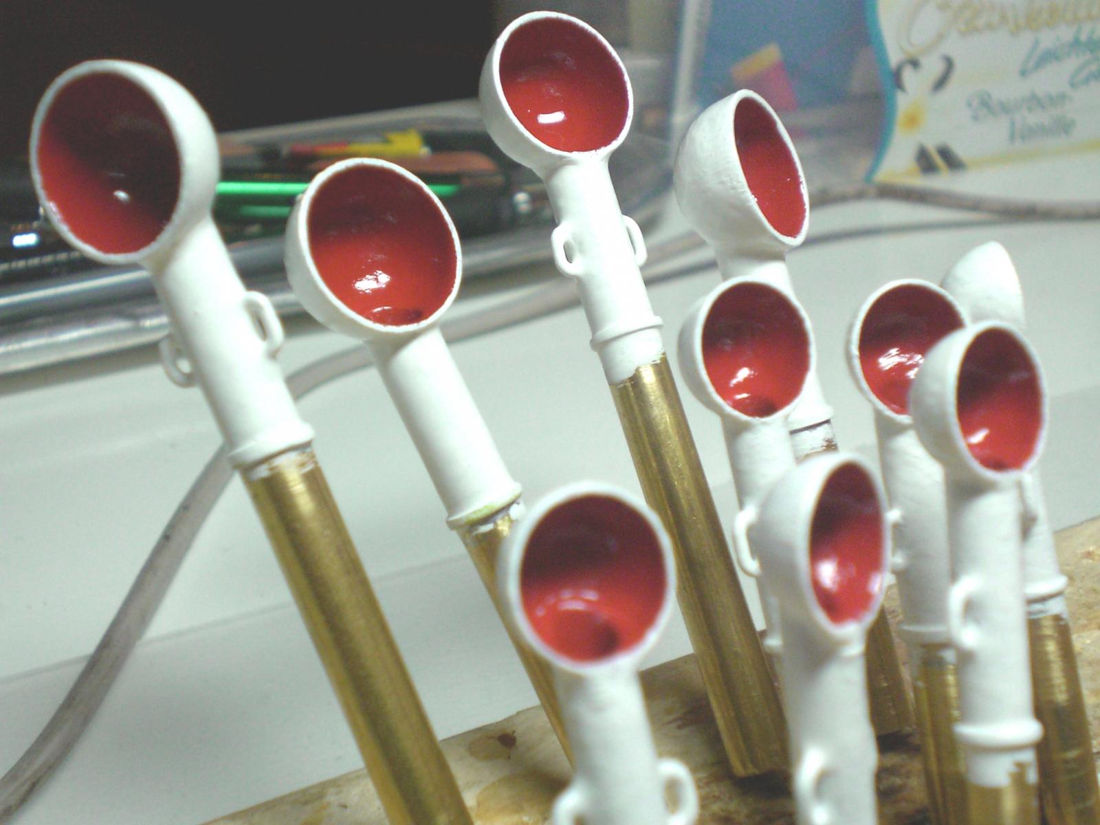
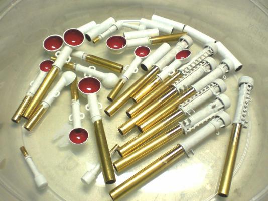
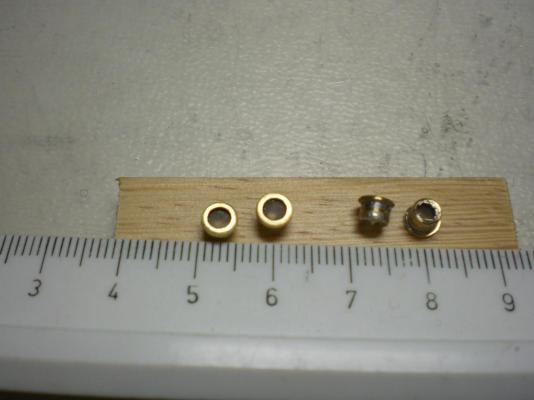
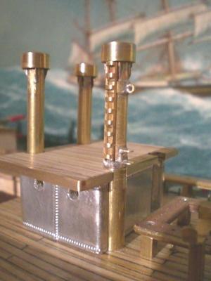
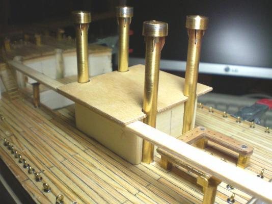
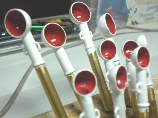
Hi Michael thank you the vents are made from cut off dome nuts and brass tube (a Little bit Fitting and soldering) Please refer to my "Heinrich Kayser" build log, part 8 if you like Nils ammendment.... Michael, here is a quick 3 minutes handscetch, in case you refer to the vents of the deckhousings Nils

-
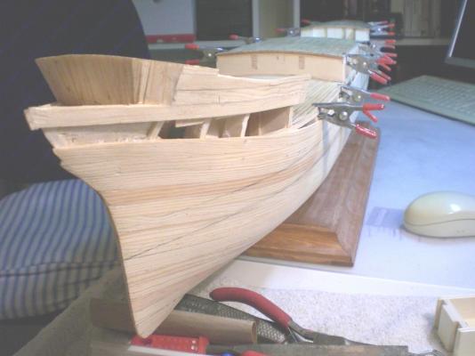
Bob, the deck Planks are cut from pine. I think the etheric pine-oil in the cut Wood brings this nice warm natural structured tone. It smells wonderfull during cutting and sanding, takes on the PA glue very well and is easy to bring into shape. There shall be more metal work to come later on, because all hollow masts, Yards, etc. are of brass as well as the many winches. Nils
-
Well Popeye Thank you... I´m happy to share this with the MSW comunity if it is of help for the fellow members Nils
-
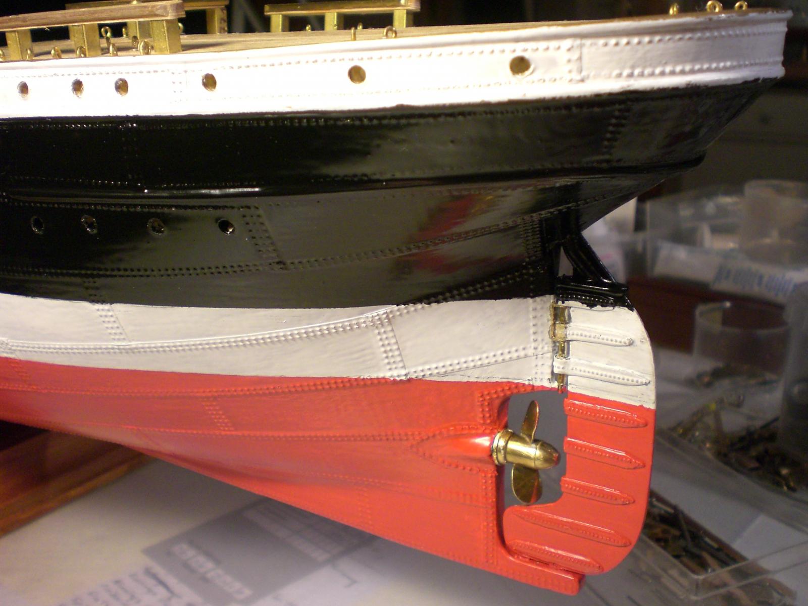
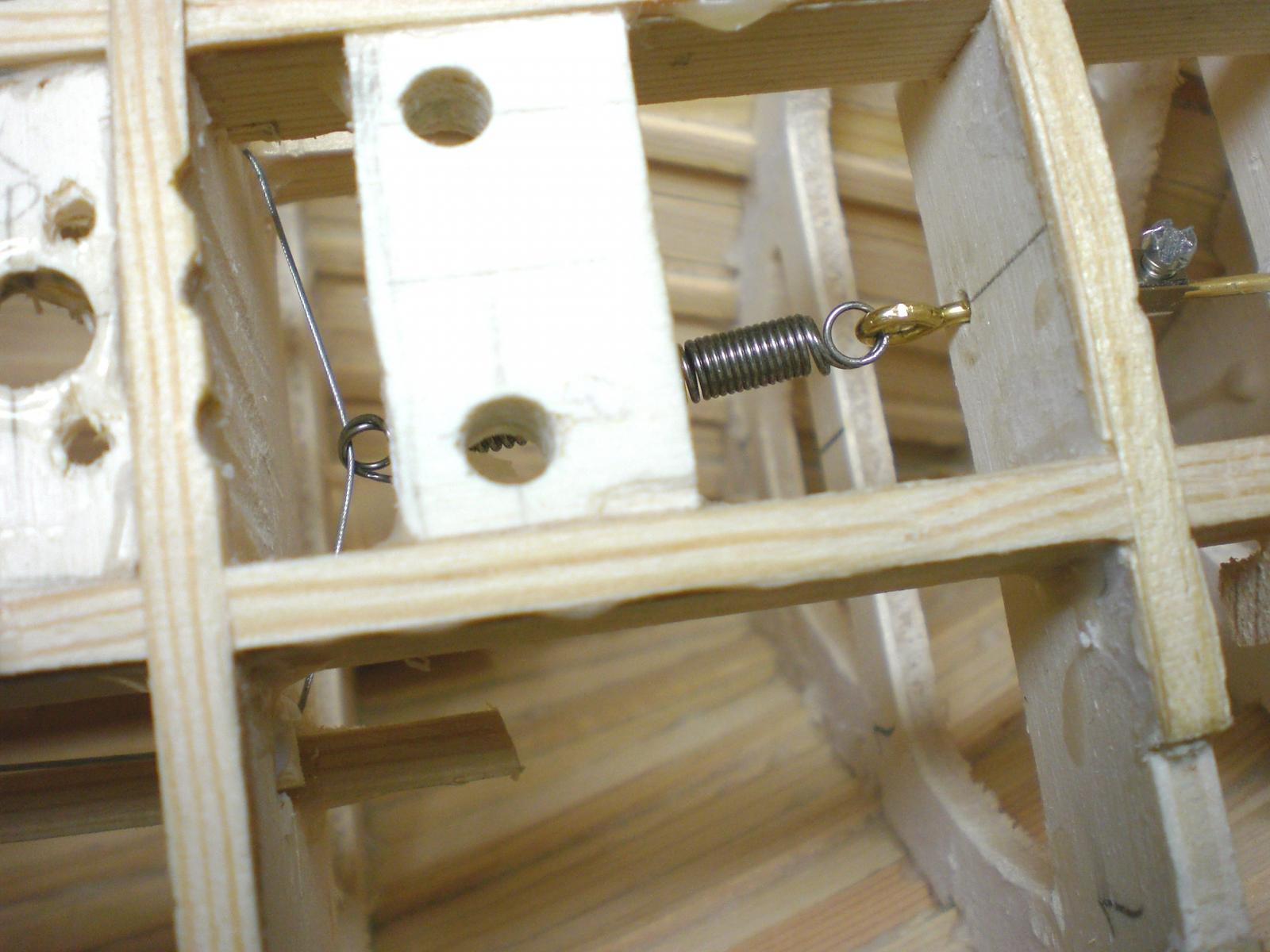
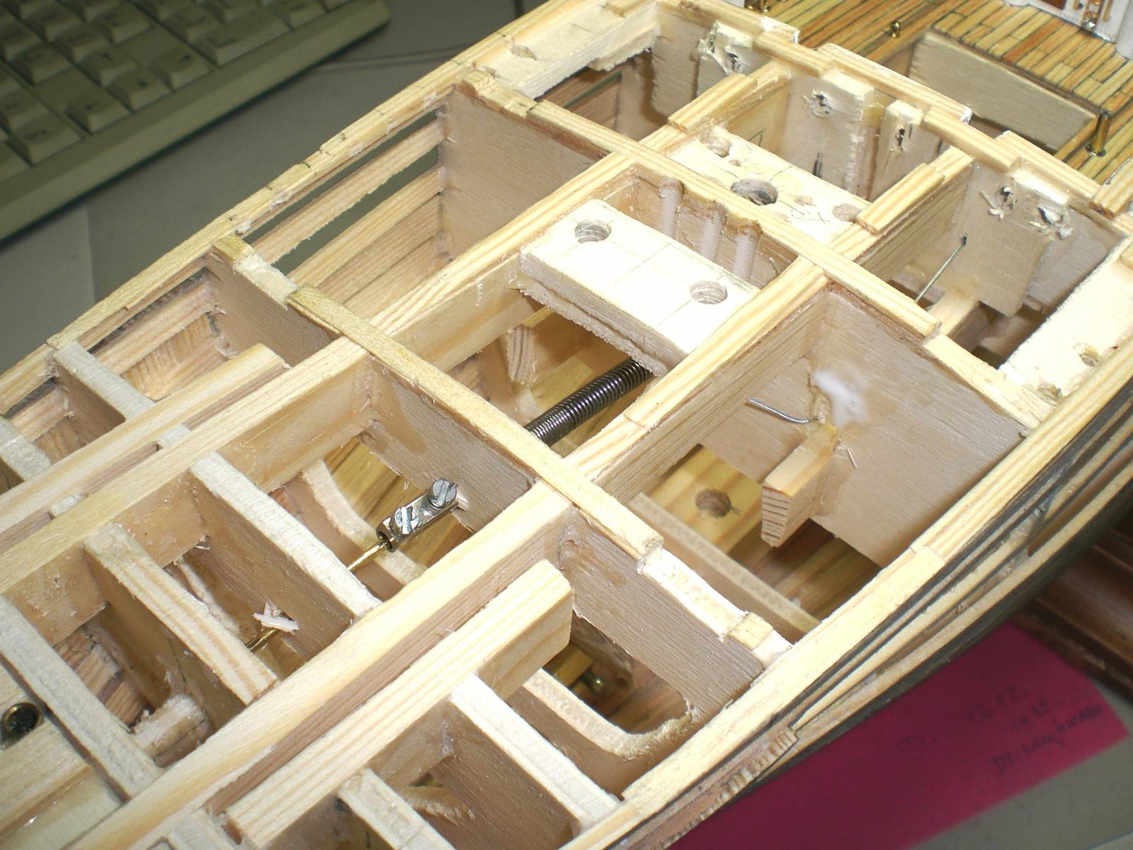
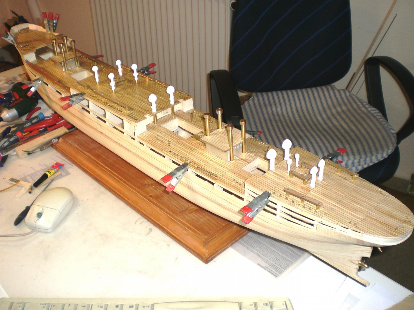
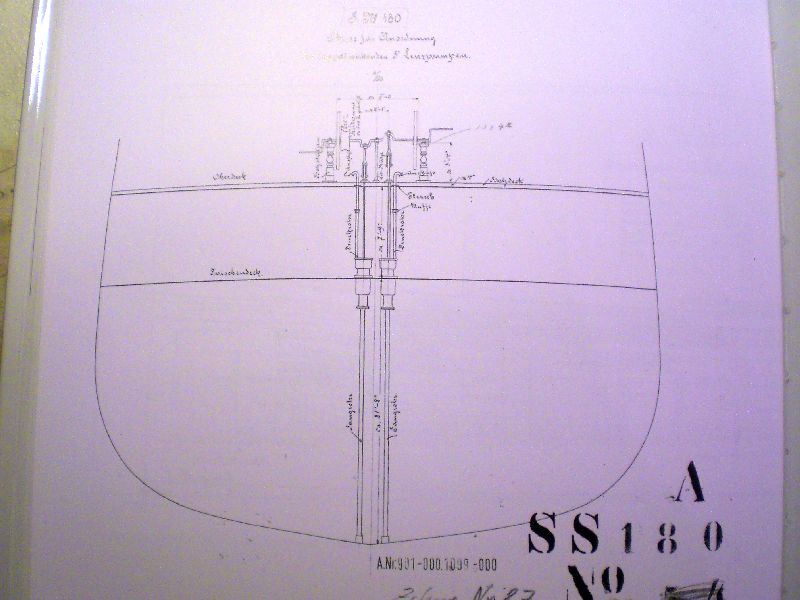
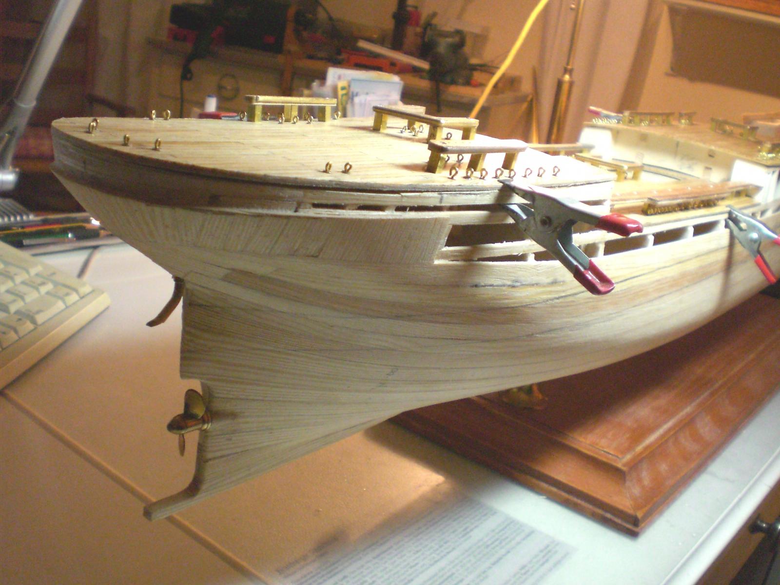
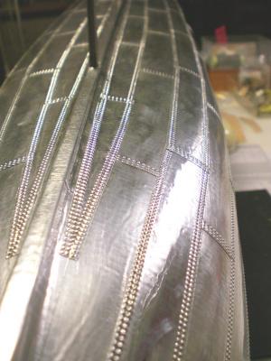
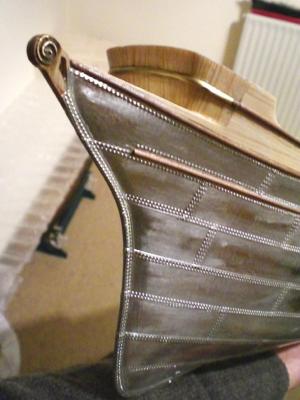
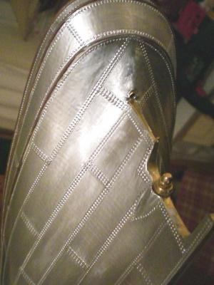
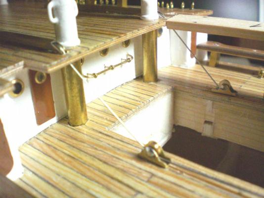
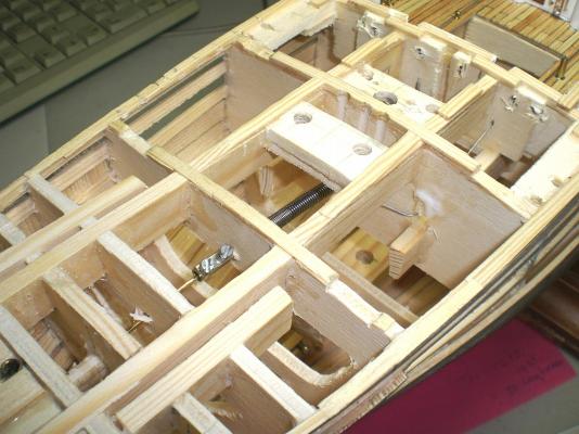
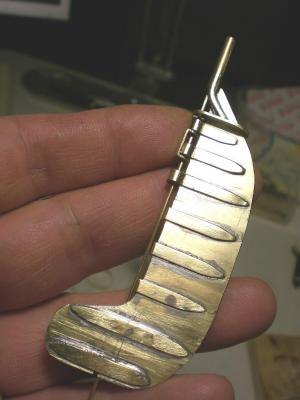
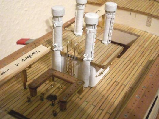
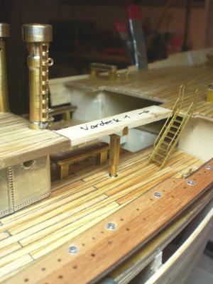
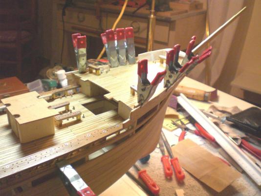
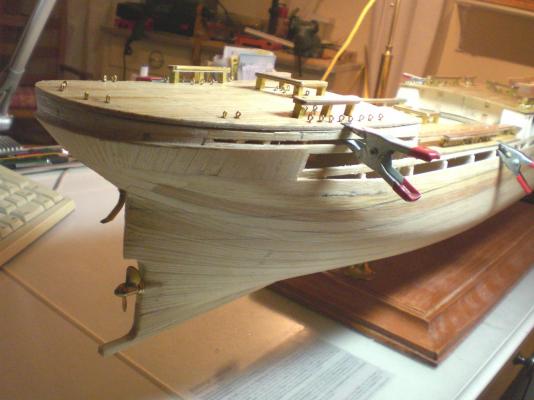
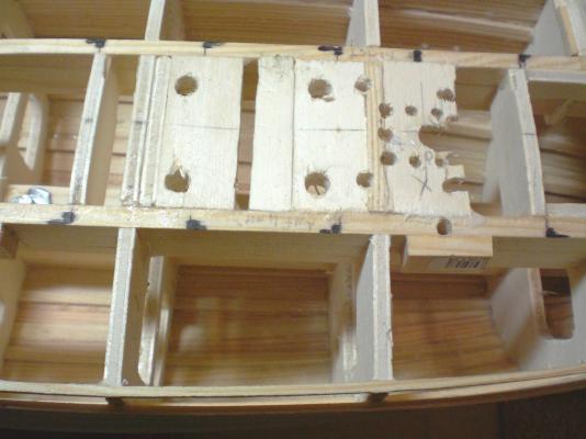
Build log part 11 fixed a spring loaded steering chord strummer, adjustable spanning device the steering (tin galvanized steel chords) come down from aft the highdeck and are guided over the aft welldeck, through the first two Bulkheads of the poopdeck, to where the spring is attached in the Center keel "spine" (in Picture starbord of the spring) the 8,5mm hole-notch for taking up the 3rd mast safely, can be seen the steering device leads into the highdeck wheelhouse in covered square protections and is guided on along the aft welldeck These are the two Long vents, they are still removeable and swivilable like all vents somehow the Pamir Needs to steer, so here Comes the Balance type rudderblade a Little riveting to it..... and here now starts the riveting and plating of the hull more to that in the next log part for those of you who had already watched the plating of my steamship "Heinrich Kayser" one would say.... as usual.. Build part 12 to follow.... Nils


- 269 replies
-
- 12
-
-
Thank you Bugra These few metal parts are really not complicated at all, but I`m glad you like them Nils
-
Nenad and David thank you for your appreciative words Nils
-
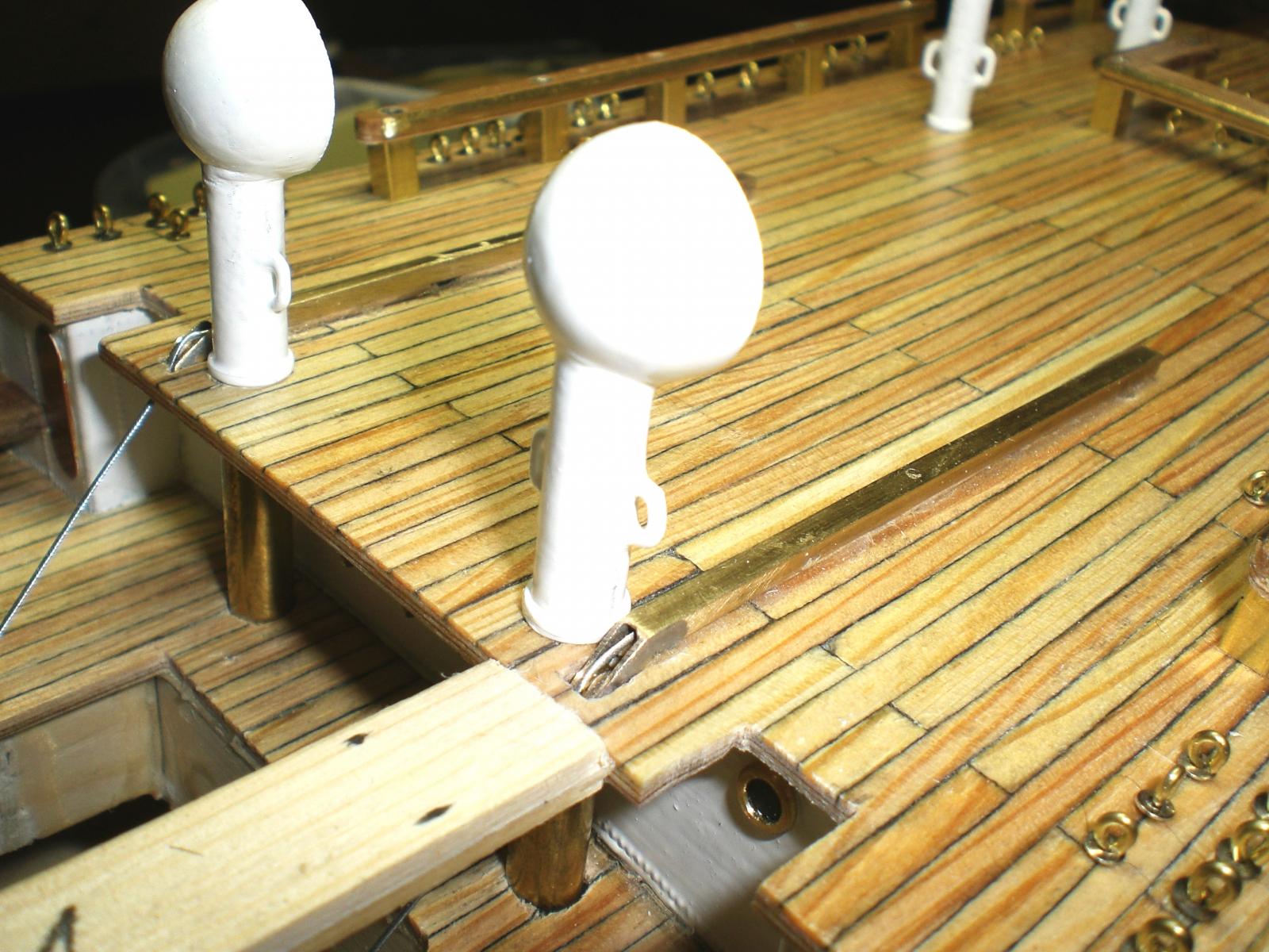
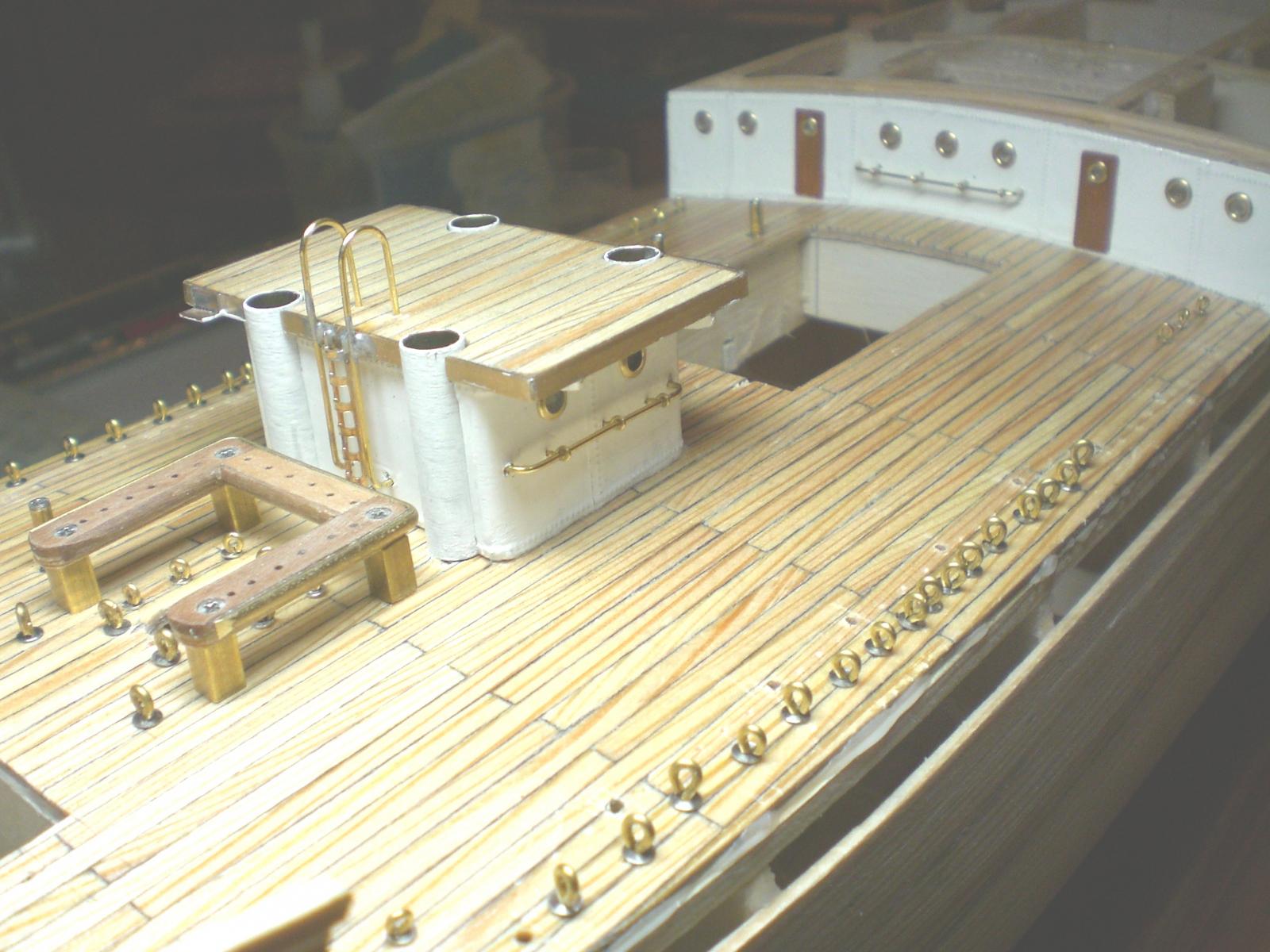
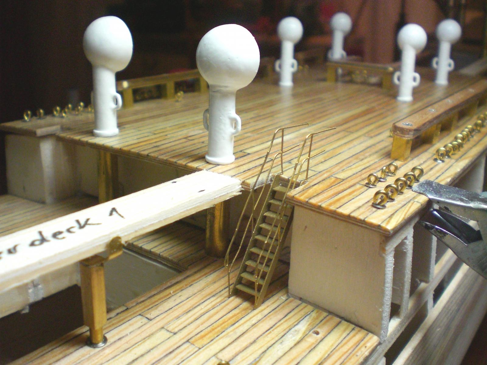
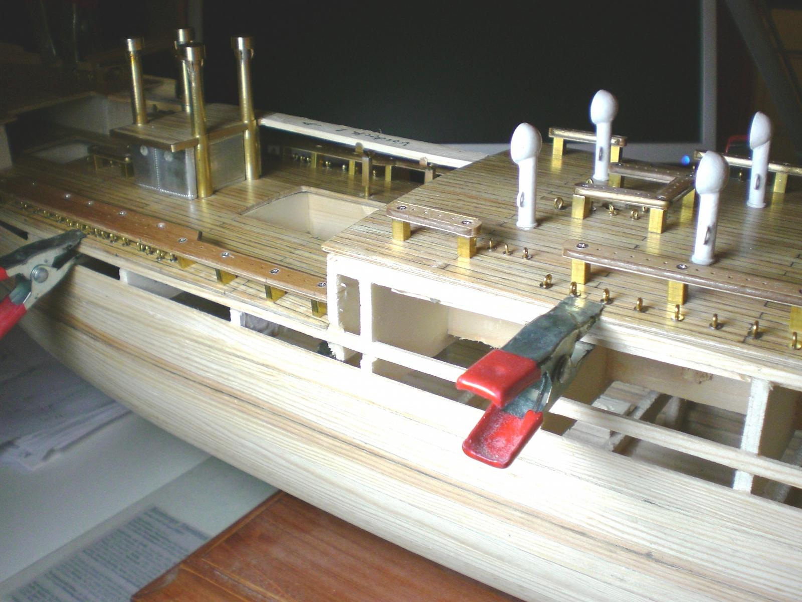
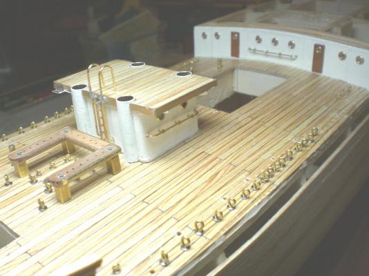
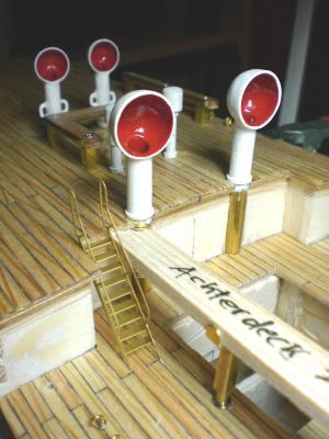
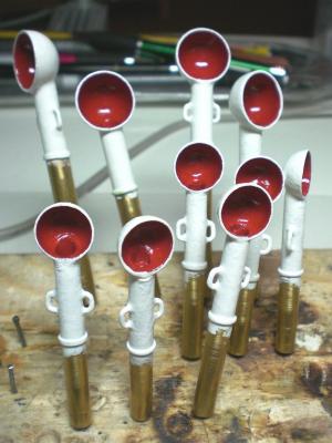
Build log part 10 Holding rails and some portholes, deck and rim mounted to deckhouse bunch of vents in all Versions and sizes made some portholes on my own (just learn by doing) Fixing doors and deck reinforckment brackets Access ladder this and the next two pics should have come earlier....(nobody is perfect) doors and under deck vents in forecastle area strong eyelets on portside to take on the shrouds and backstays tensile forces Build log part 11 to follow Nils


- 269 replies
-
- 11
-
-
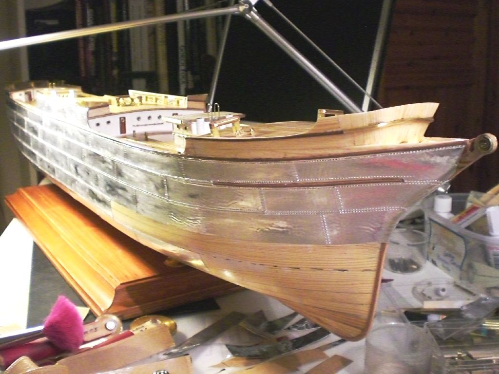
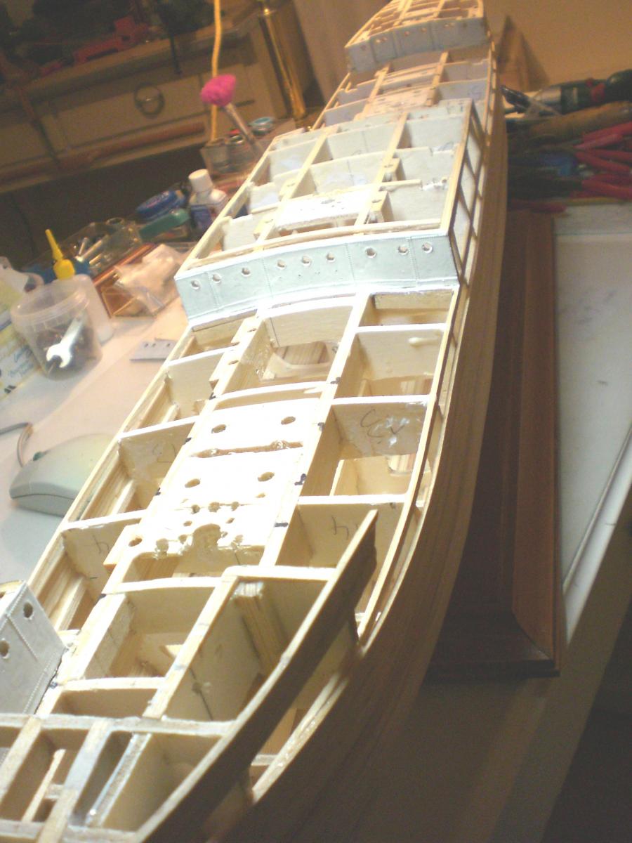
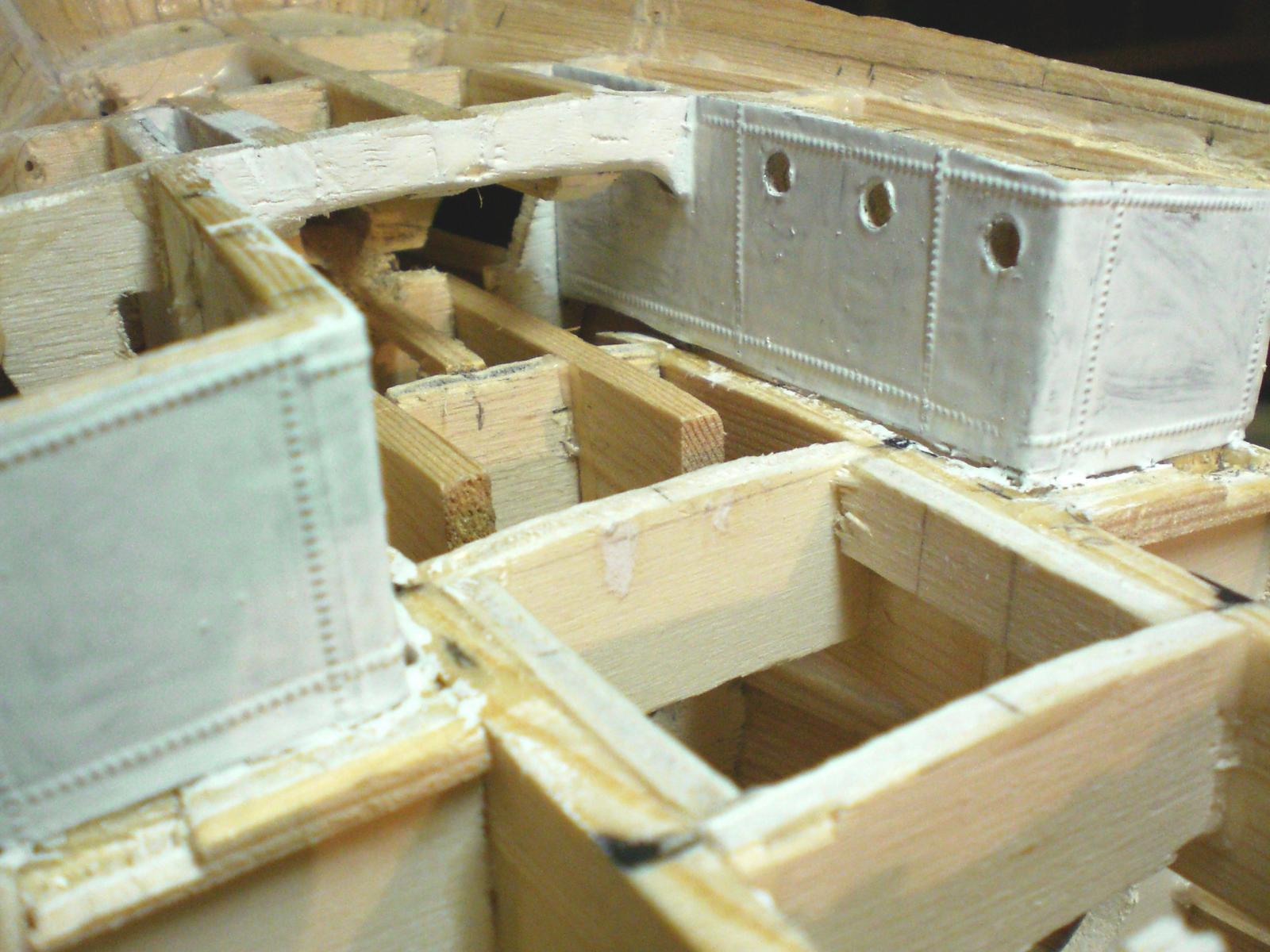
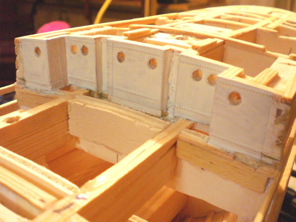
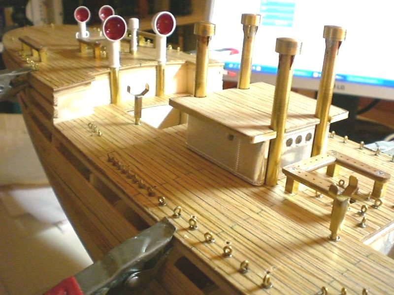
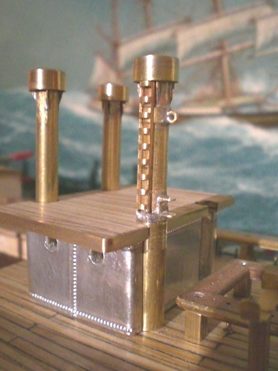
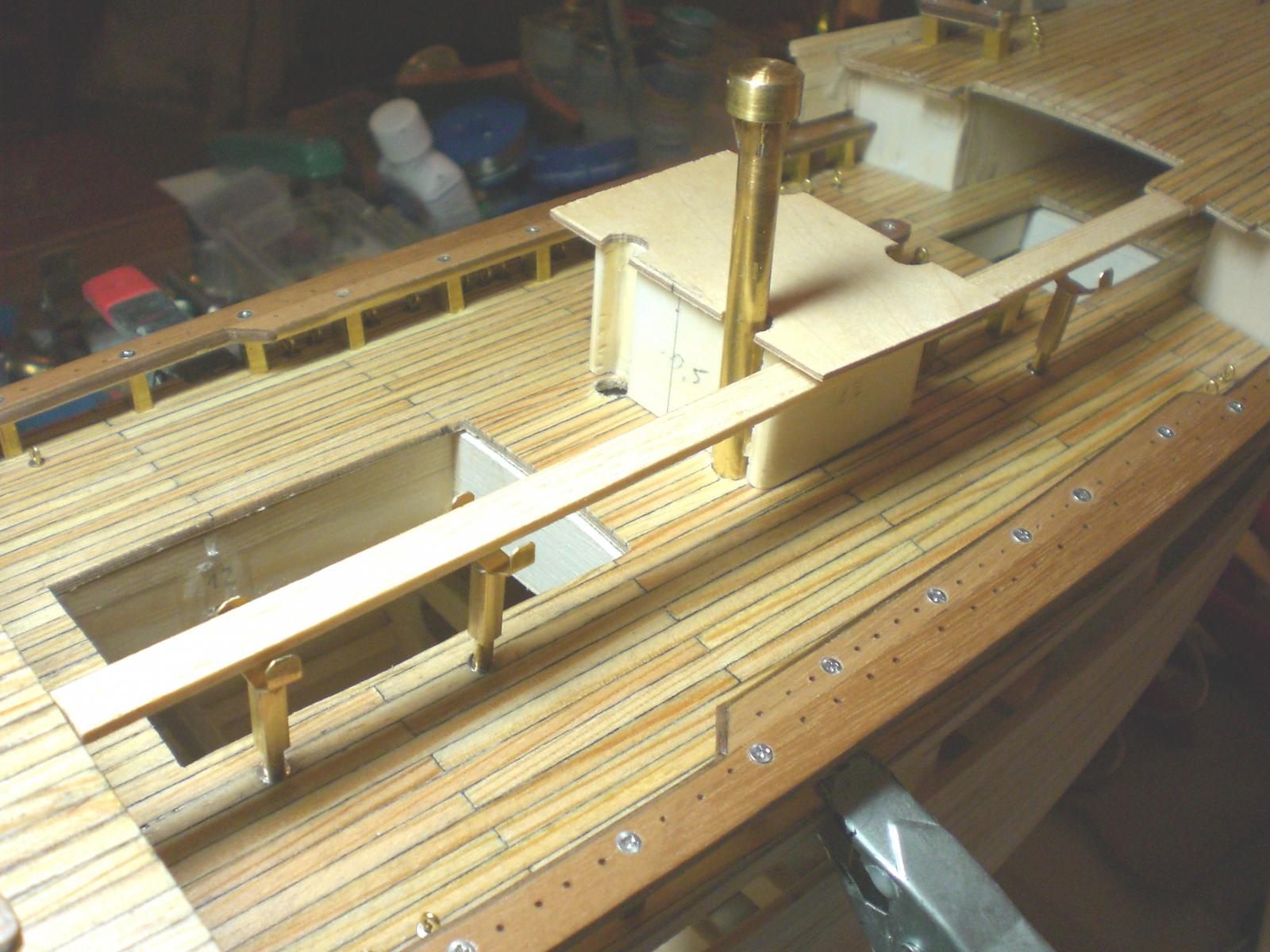
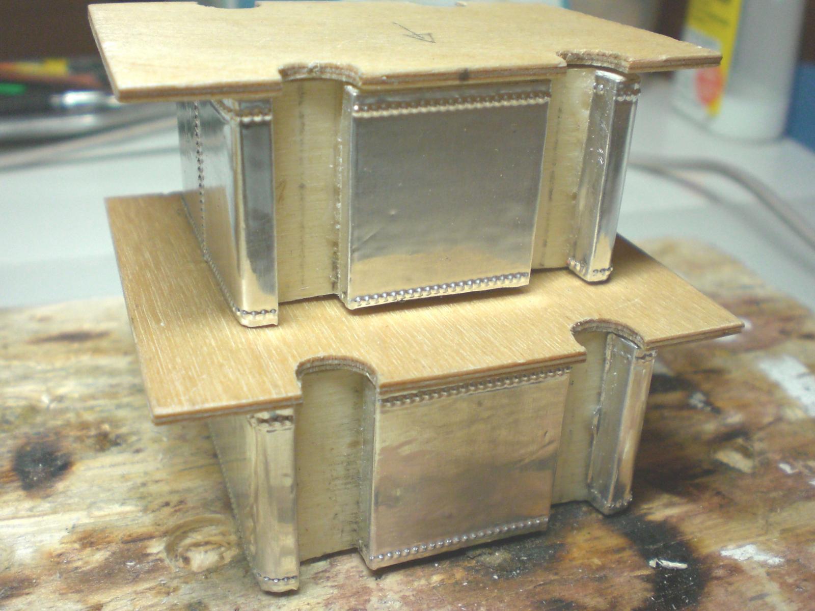
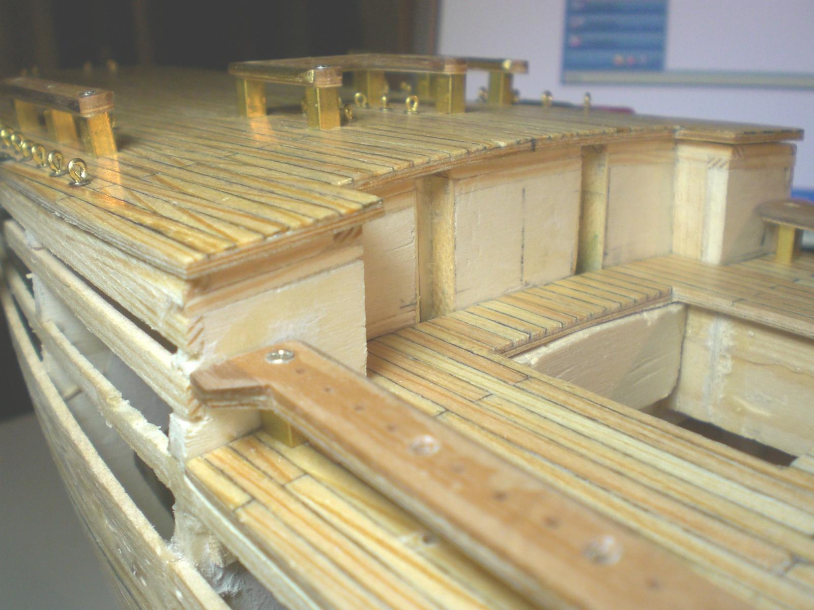
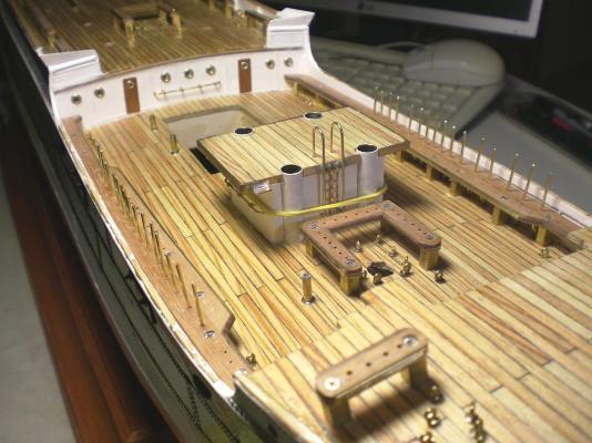
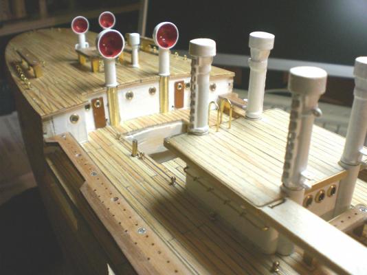
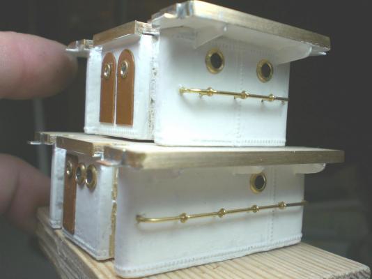
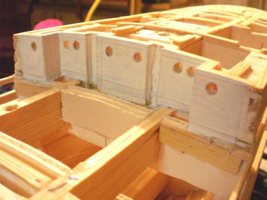
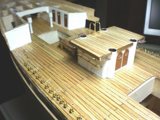
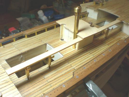
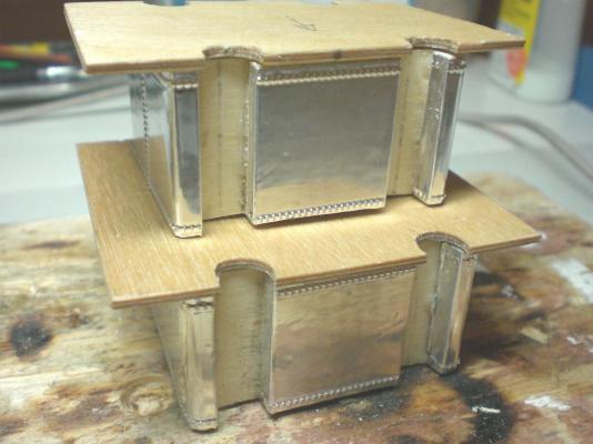
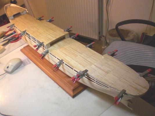
Build log part 9 now the Fitting out is slowly moving on the deckhouses had to be metal plated and painted, portholes drilled, etc, allready because they are fastend to the well-decks from below, before the decks had been permanently attached. There is hardly Access to the deckhouses any more in that position I trust not a gram of filler is necessary on the entire single layer planking, shall be nice smooth base for the metal plating the deckhouses have rims for their own wooden small decks, and for supporting soldering on of the boat supports later on The ventpost tubes for mounting the cargo derricks to become each an Access lader Fitting in the stairs here one can already imagine to what a fiddeling it shall turn out later on when belaying the mast-pinracks ( and the complete functional running rigging corresponds to the original ships rigging) the Position of the catwalk supports must be carefully Chosen in order not to interfere with the later to be placed steering wire chords that run between These Supports and along the 2 aft welldeck Hatch rims and along the aft deck housing the sleeves for the venttubes allow easy upwards removal for the ventposts for not desturbing during the build self explaining.... Build log part 10 to follow.... Nils


- 269 replies
-
- 10
-
-
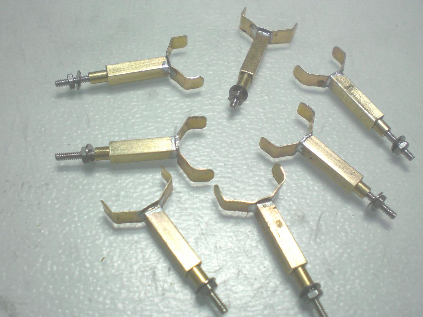
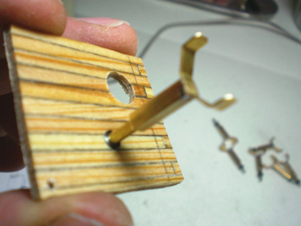
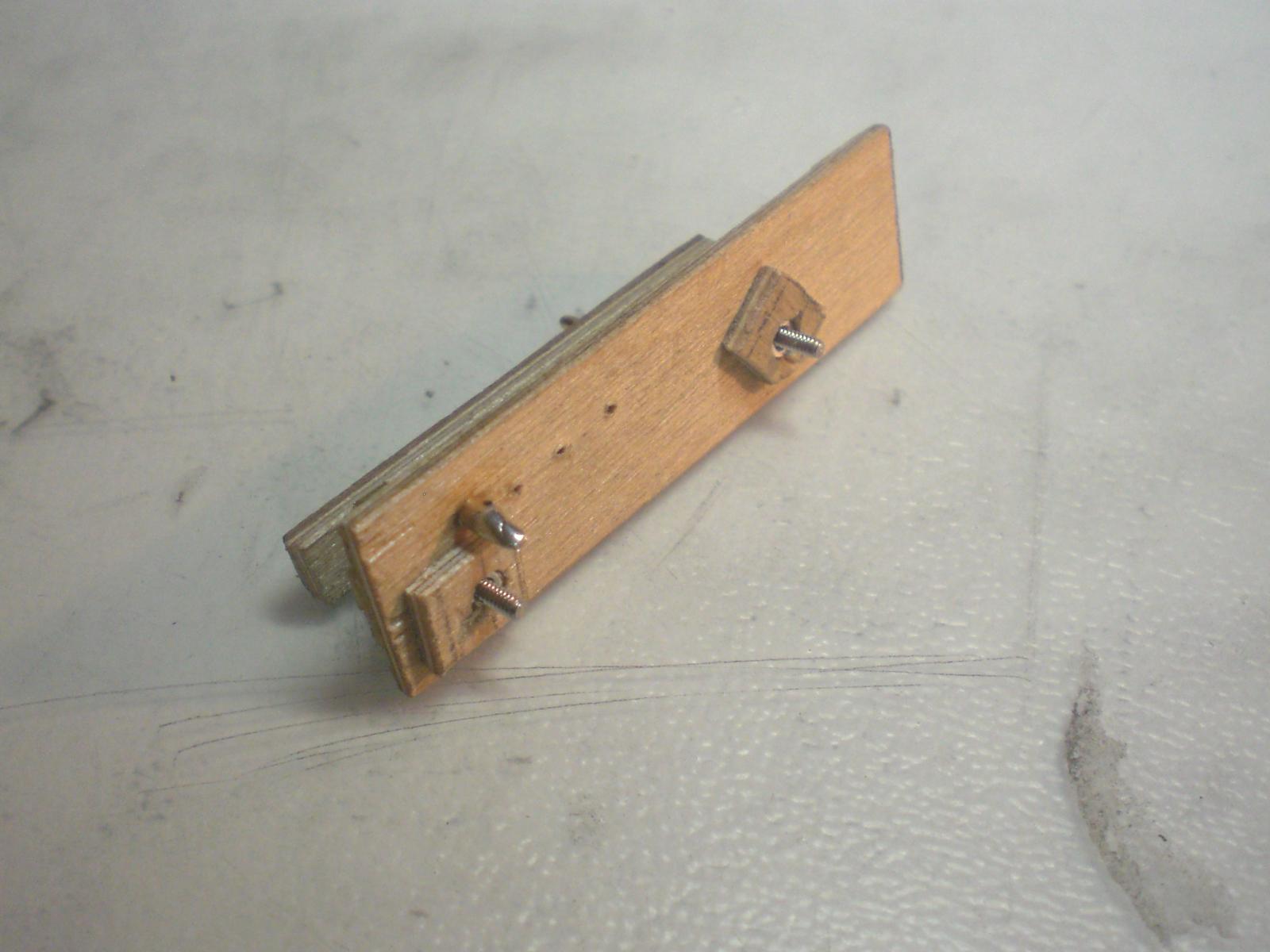
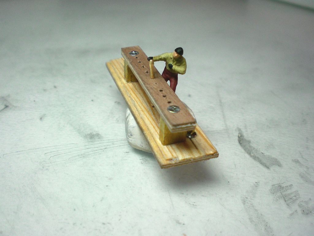
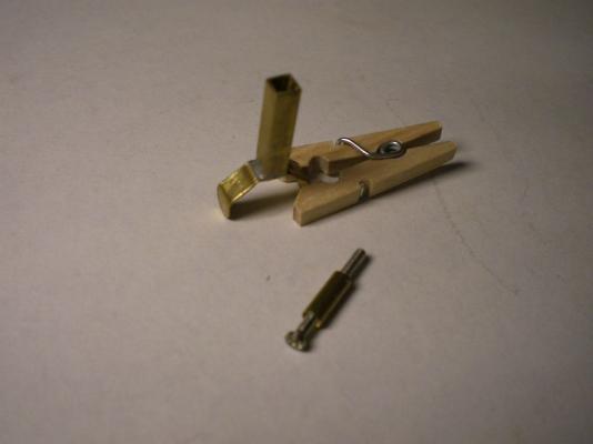
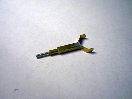
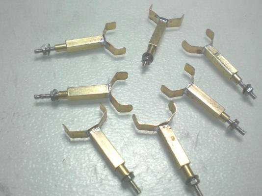
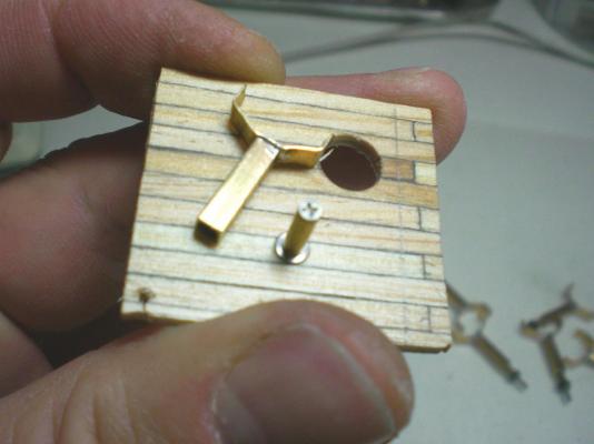
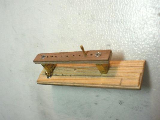
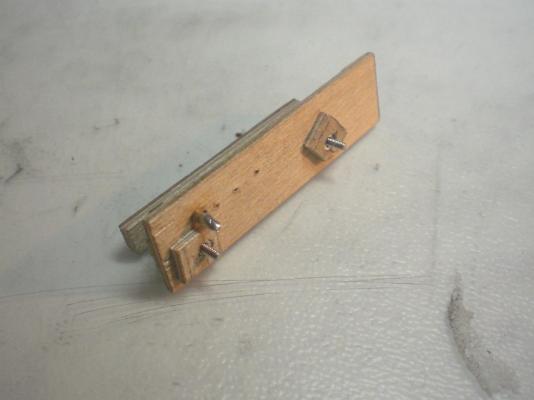
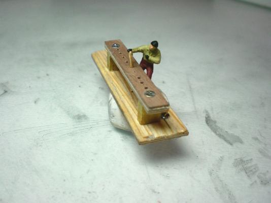
David, because I needed some supports that would withstand some Little bumps and touchings without breaking during the build, I found the solution shown in my log part 8 and here.. The Little bent to shape brass Strip on top is self explaining (fit to suit) the brass square tube is 3.0 x 3.0 mm, wallthickness 0.25mm the brass round tube is 2.5 dia with wallthickness 0.3mm, leaving an nominal opening centerhole of 1.9 mm, just enough for putting through a philips head screw with M 1.6 thread. the screwhead has to be reduced a bit in Diameter, so that it does not hinder the squaretube to be slipped on in tight fit. The screw Centers itsself by means ot the tapered screw head. This combination allows Support Setting (tight fit) to the hights and to whatever is to be supported. Nils for Fitting to the deck you might Need to put a Little beveling to round tube end in order to compensate the deck curvature at the requested Position,for upright Support Standing, and to fit tiny flat washers under the tube and under the Counter nut on the deck underside. That counternut must be secured, best with a Little wooden Cage and with CA glue
-
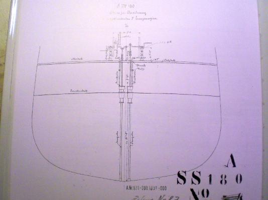
John the (from outside) visible decks were all from finest steel riveted plating, but they have as well been covered with 3.5 to 4 Inch thick wooden oregeon pine planking from begin on. I unfortunately do not know to what degree the Wood may been (if at all) exchanged during 1951 and thereafter, but the Pictures Show that there was still Wood planking. One deck lower ( Tweendeck) was only steel plated I am adding a Picture out of Gondesens book showing the decks planking on top of the riveted steel plating, and the plain steel riveted tween deck. The SS 180 on the drawing stands for Blohm & Voss build No. 180 that is the Pamir Nils
-
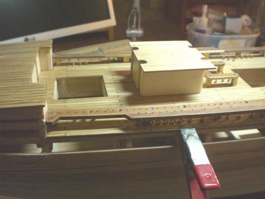
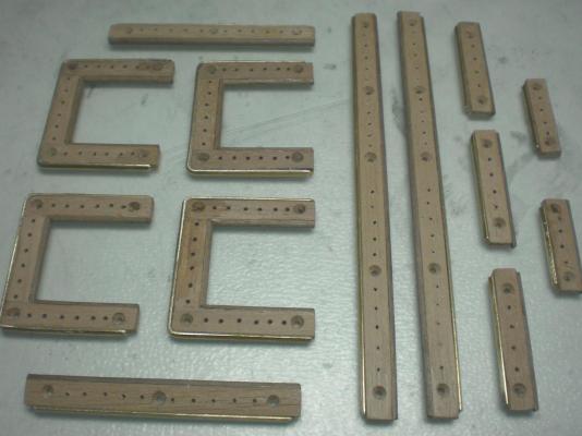
Build log part 8 all decks and the two deckhousings fitted doing the forecastle bulwarks, bow jib boom mounted set of supports for catwalks model for hight adjustable support the two appropriate parts taking measurements with dummy catwalk plank the vent tubes with their Hoods are preliminary mounted the two deckshouses with notches for the venttube sleeves different sizes of vents the two Long ones go to the aft side of the midship highdeck Build log part 9 to follow Nils

- 269 replies
-
- 10
-
-
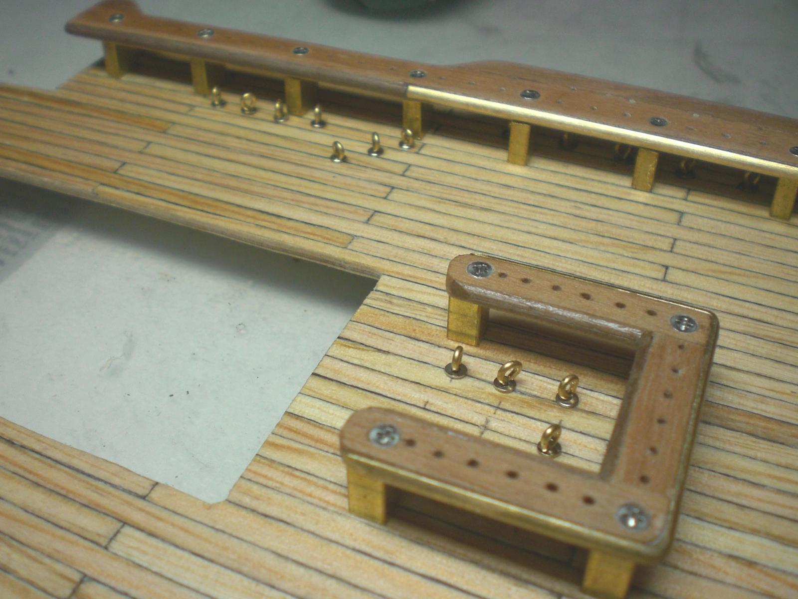
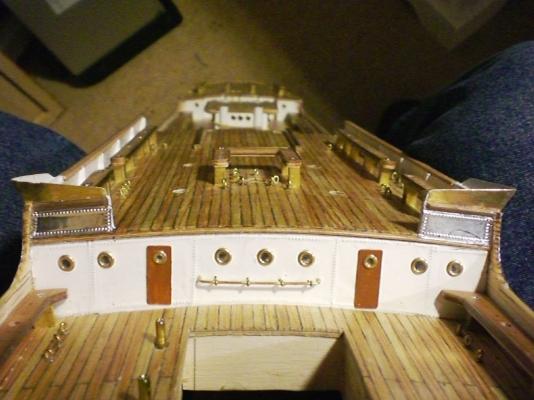
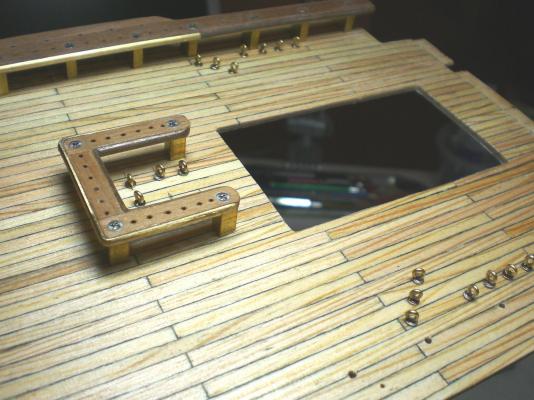
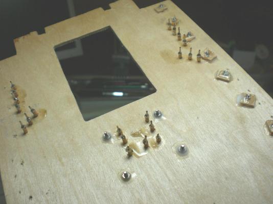
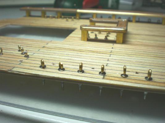
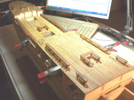
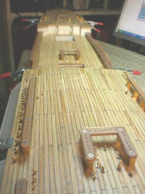
Build log part 7 bow bulwark planked but not sanded and not trimmed yet aft maindeck with outcut for hatch Counter measures below the deck aft maindeck with port side fitted pinracks and mastgarden The Philips head screws are stainless steel and M 1,4 thread eyelets on starbord side aft maindeck new deckhousing starbord pinrack also mounted final fit check poopdeck Need to give round openings for to pass through the vents of deckhousings and for Counters of the eyelets around the masts area Build log part 8 to follow Nils


- 269 replies
-
- 10
-
-
Hi Robin Oh yes, that will be nice, I`m looking Forward to your Photo, and thank you Nils
-
S.Coleman, Thank you for your words, the Tacklings of the belaying Pins afterwards cover the Philips srews heads to a great degree, (not obvious to see any more), so I leave them as is..., I also have the possibilty to tighten the screwheads after the Setting pull in the rig Needs some readjusting. Nils
-
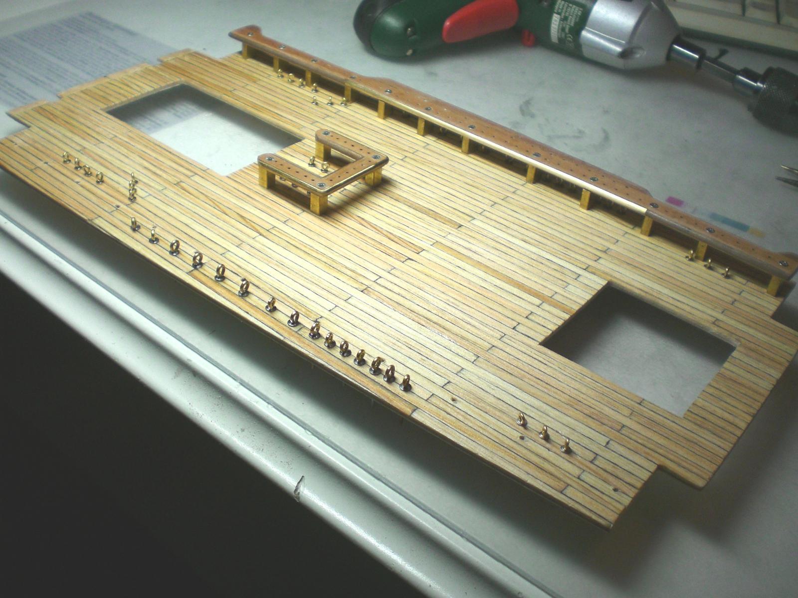
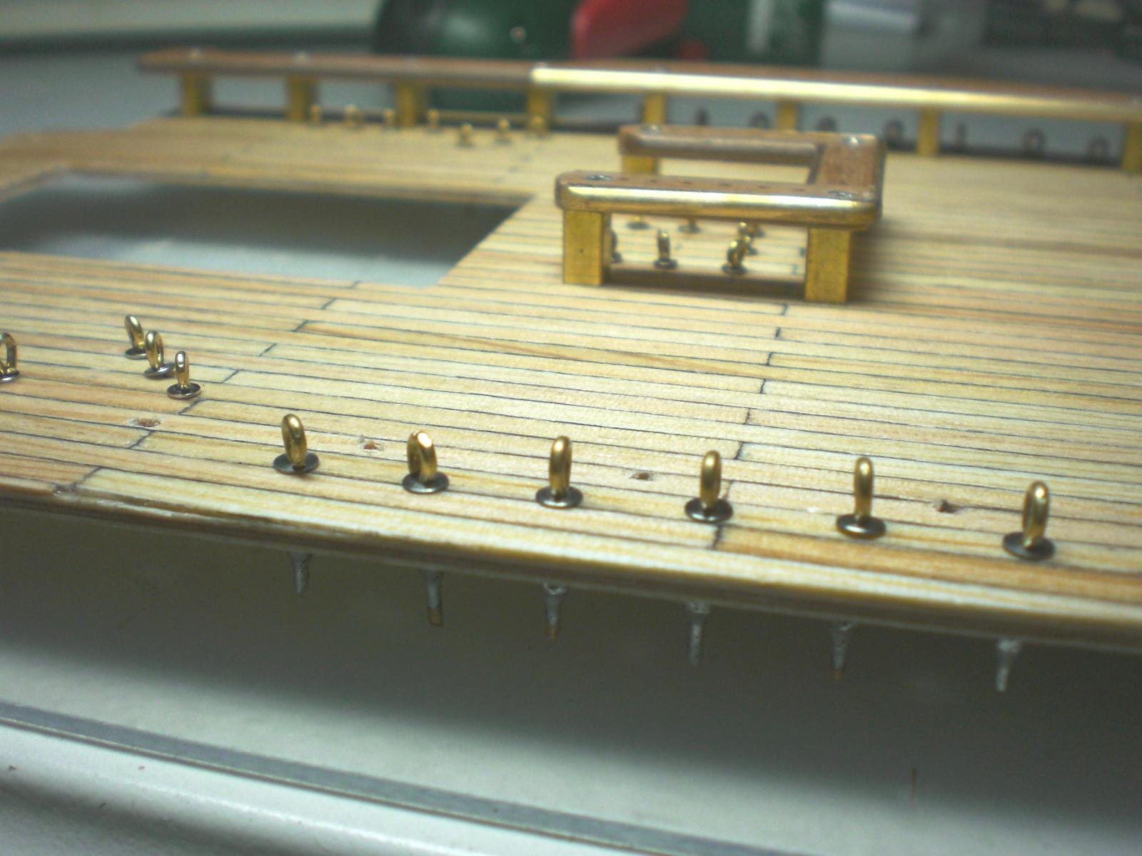
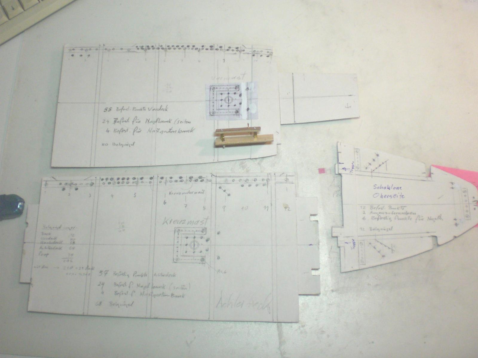
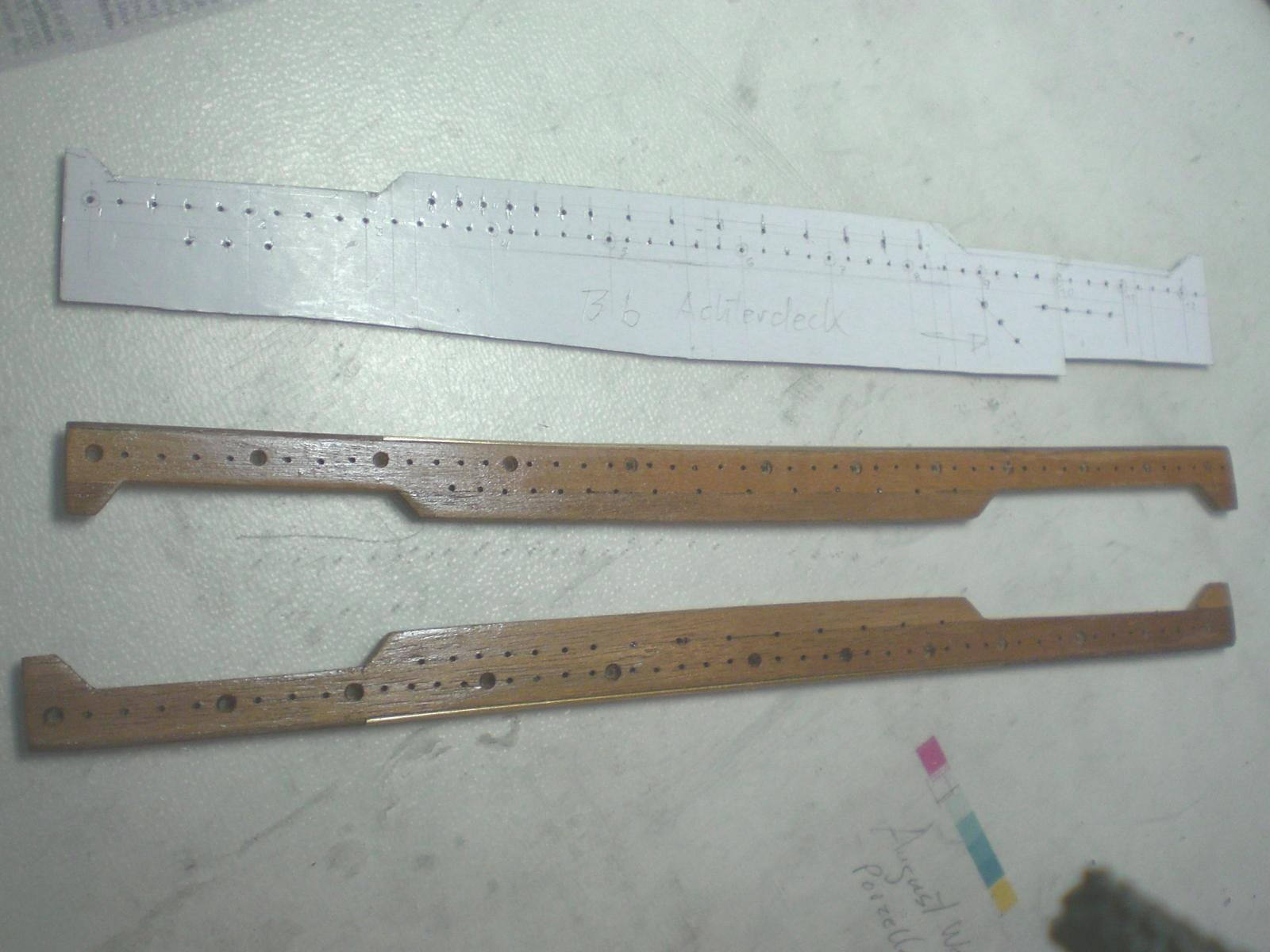
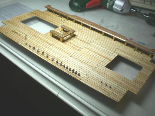
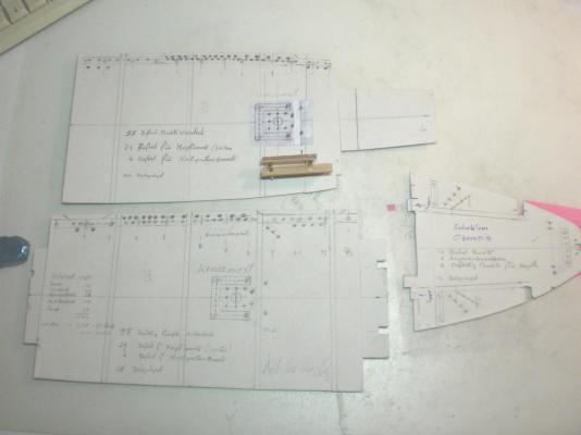
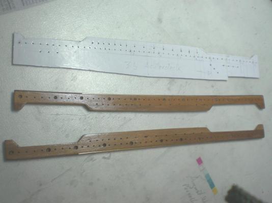
Build log part 6 here is a terribly bad and wrong glued together wreck of the 1951 version (Heller 1:150) Pamir Hull, built by unknown...., but I saved it from the bin. It Looks like it ran on to the rocks of Cape Hoorn, but never the less I was only after taking cross check with the own 1:96 hull dimensions. I even sold that hulk at Ebay afterwards to someone else and for the same reason. By the way, the assebly instruction Manual of the Heller kit, for whoever is able to get an exemplar, bears amoungst other valuable information, beautiful Explosion typ drawings of all individual parts, a great help ! leaving open the last Planks came very Handy for clamping down the decks started to begin with several cardboard templates for the belaying pin racks Arrangement. It was my decision to put all the rig (static ad running ropes,lines, chords, stays, Tacklings, bracing tackle, etc...) in full functional way to the rig. I asume there is not a Feature not modeled in to this ship here just a Little Trial model important to fix the Counters on the bottom deck side, same Little model in accordance with the handscetch a made before some of the many pin racks, semiround brass edge on the rope wear side, wooden semiround on the other These also take up the shrouds- and backstay fastening bolts as well as the many individual pins all eyelets have sufficiant Counter Points beneath the decks eyelets within the mastgarden racks Build log part 7 to follow... Nils
- 269 replies
-
- 17
-
-
Hi Crackers, when using the "Quote" button to your last message I get an error note, telling me that I´m not allowed to use That ending ?????, the Quote Feature works OK with all other members return Information As for considering perhaps the light cruiser Emden, my preferance lays more on civil ships (exception 17-18th century war ships which I love for the beautiful lines those naval architects were capable of building). Unfortunately I shall Need to pause anyhow, because I`m running out of space for putting the models Cheers Nils
-
Thanks again Bedford, cheers Nils