Mirabell61
-
Posts
7,406 -
Joined
-
Last visited
Content Type
Profiles
Forums
Gallery
Events
Everything posted by Mirabell61
-
 Thanks Scott, a nice comment of yours, enjoy further on... Nils
 -
Thanks for visiting my Little shipyard Greg, enjoy the further log parts if you like Nils
-
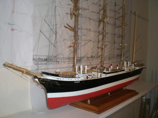
David, I asume you mean the Overall shiplength and not something else ha ? I measured 120 cm, and for a furcoat we`ll have an eye open when next fleamarket takes place. I bought her a VW beetle already, but she would`nt be happy with that model in 1:48 Thanks for your appreciative words Nils
-
Thanks for stopping Micheal, many of the Digit pics have been over 2 MB, so I had to reduce the size before posting, but you are right, I trust they still remain well representative for visual exploring... Cheers Nils
-
I love this Little boat of yours Peter, was thinking whilst the beginning of your log parts if These template-like parts could be magnified and used for putting a real one on keel Well done! Nils
-
Dankeschön for your words Karl Nils
-
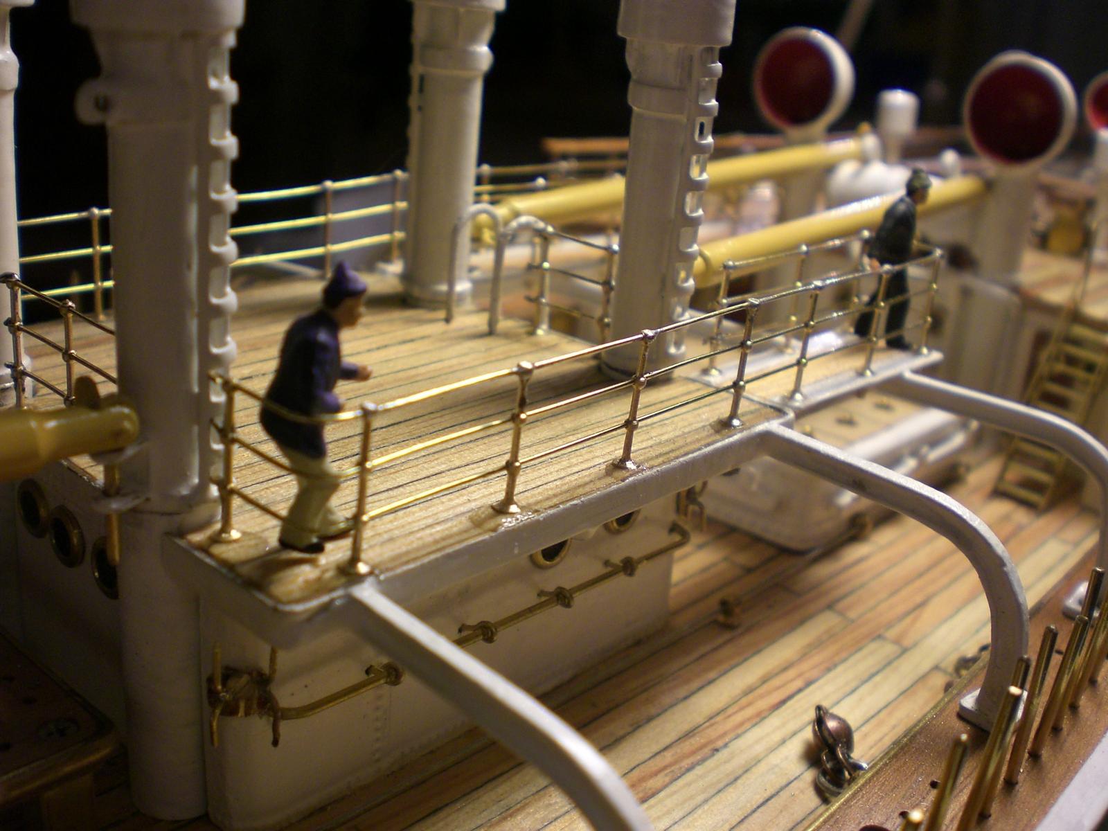
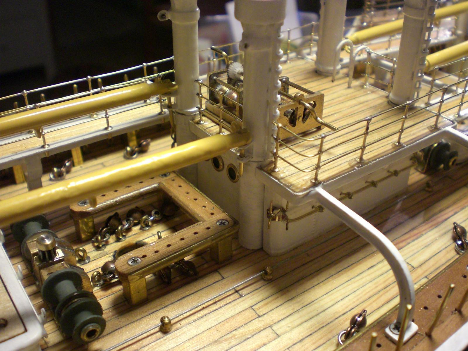
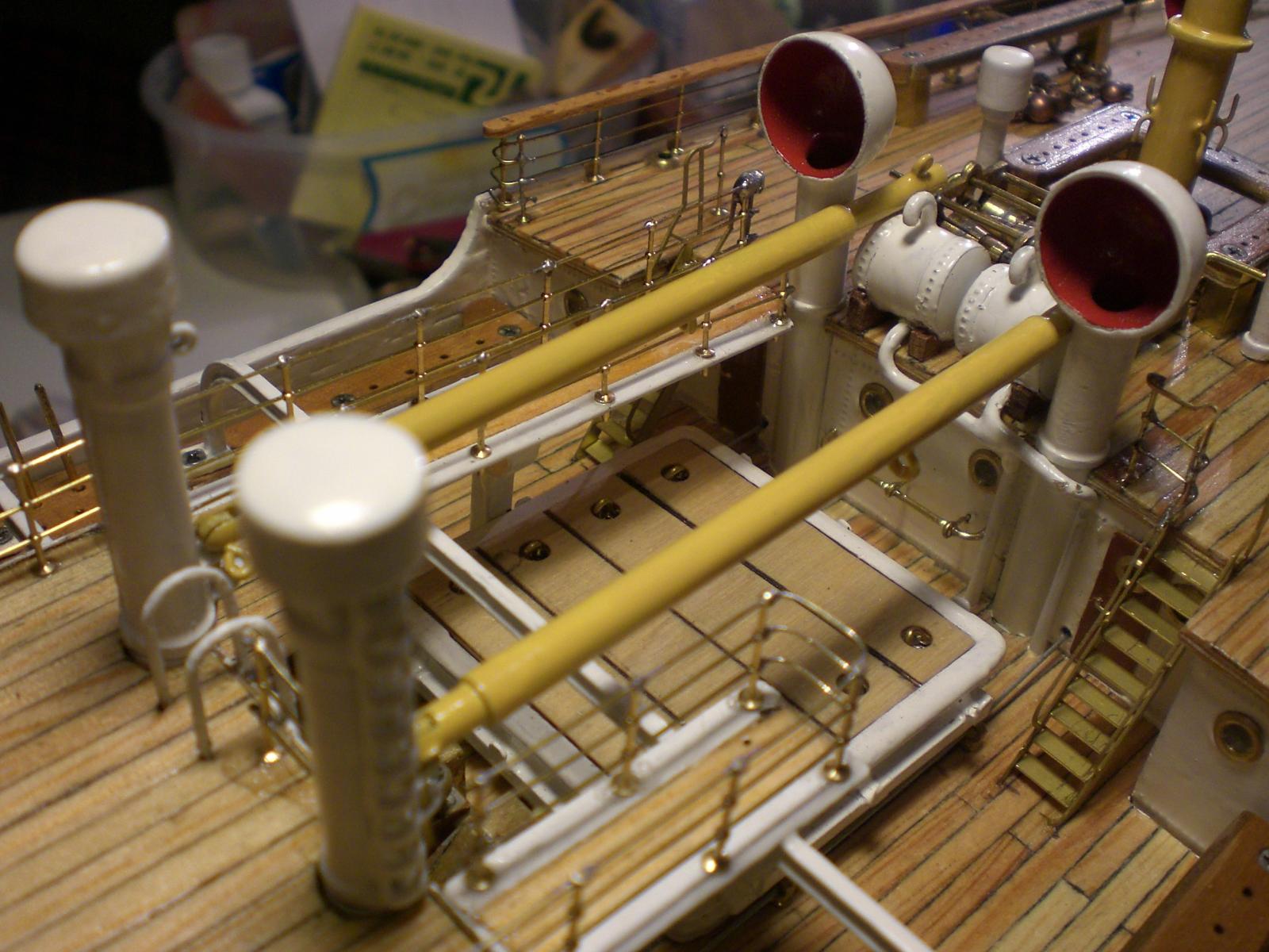
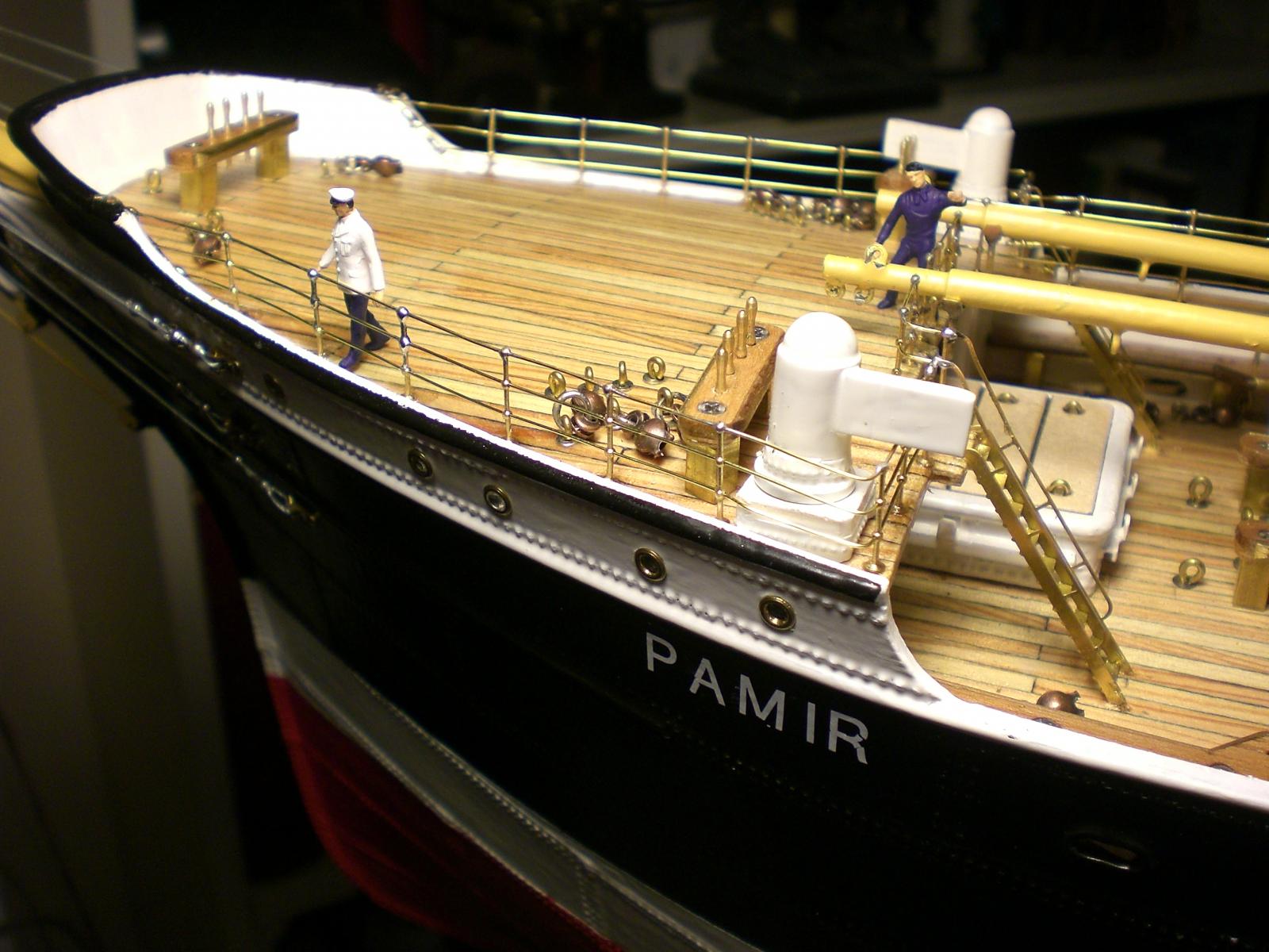
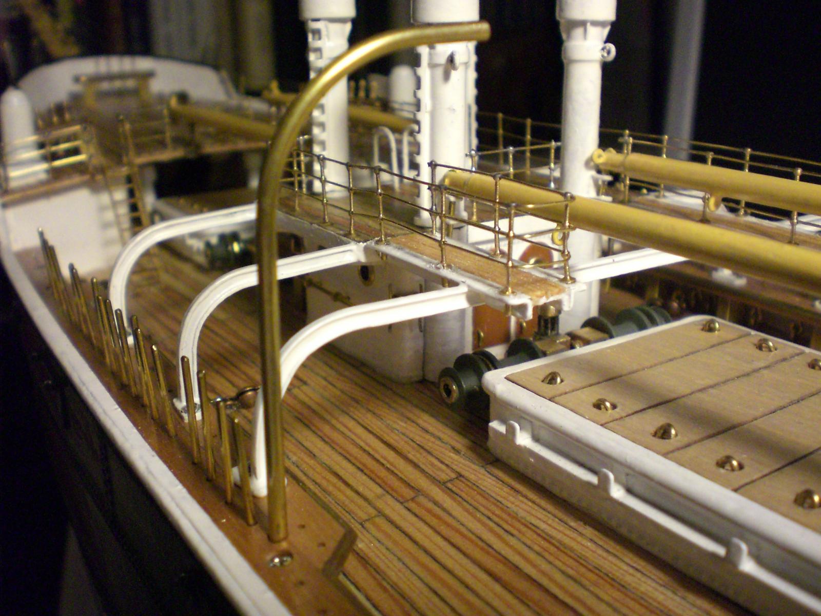
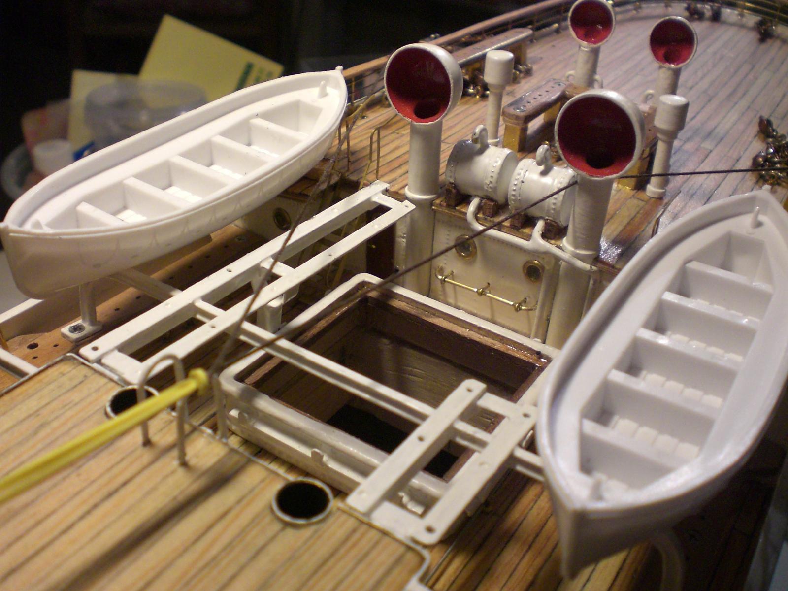
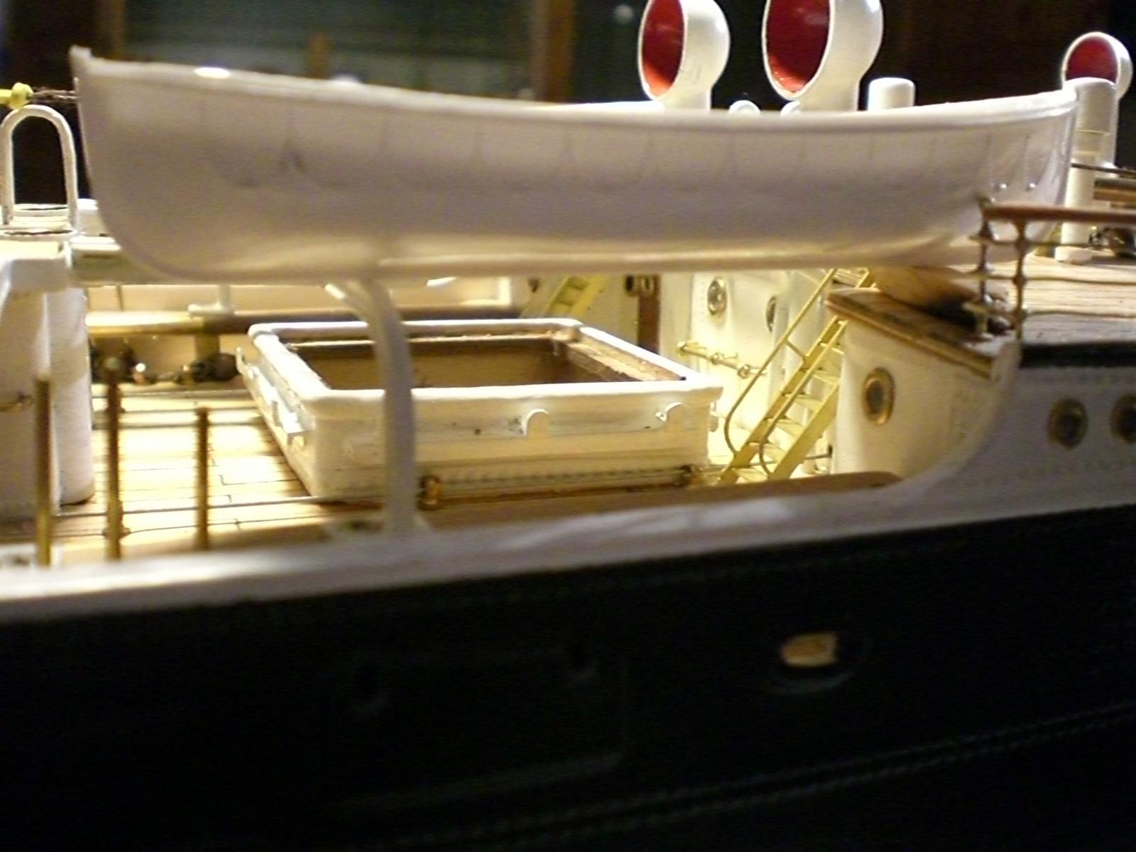
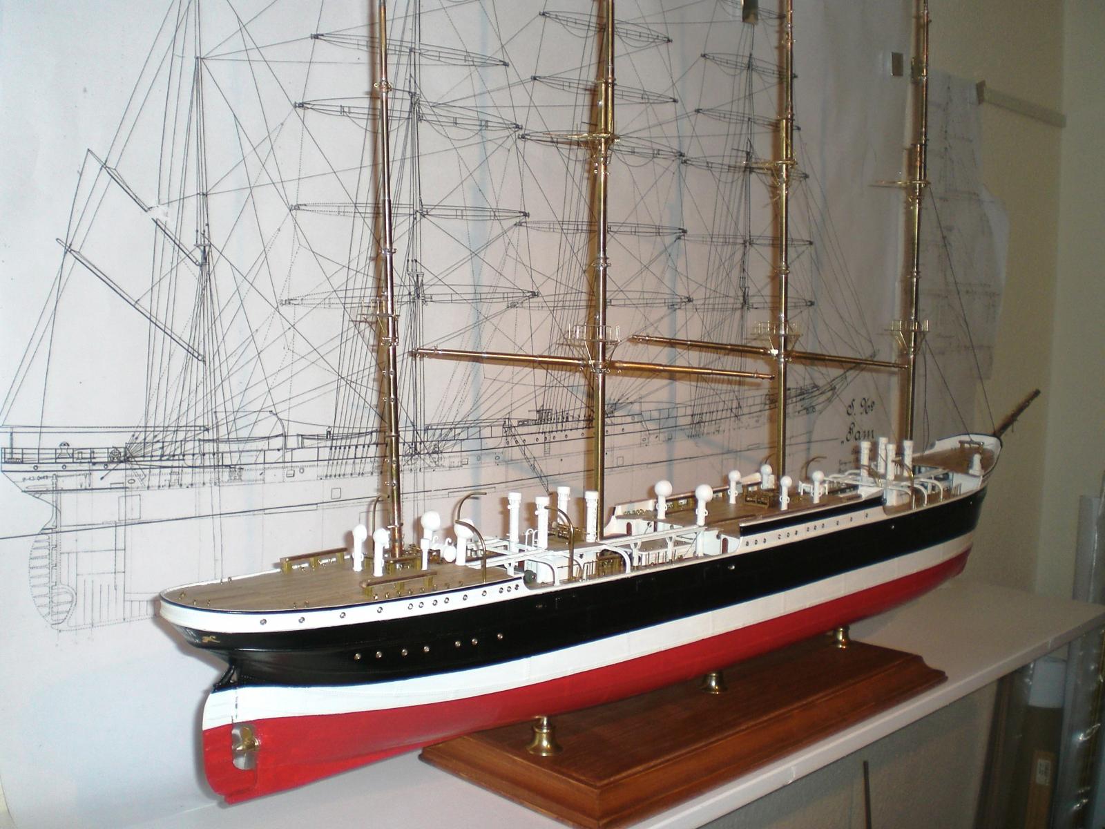
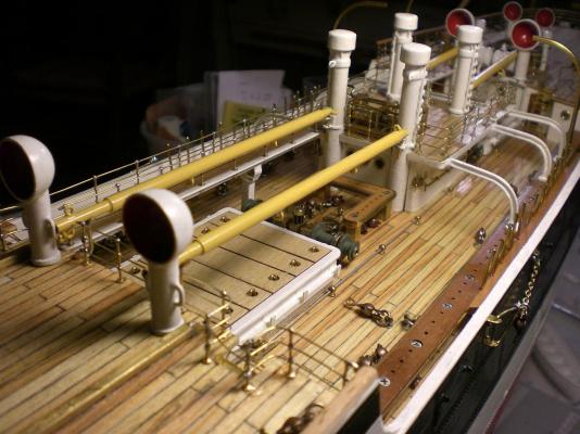
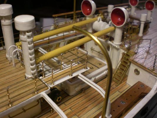
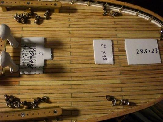
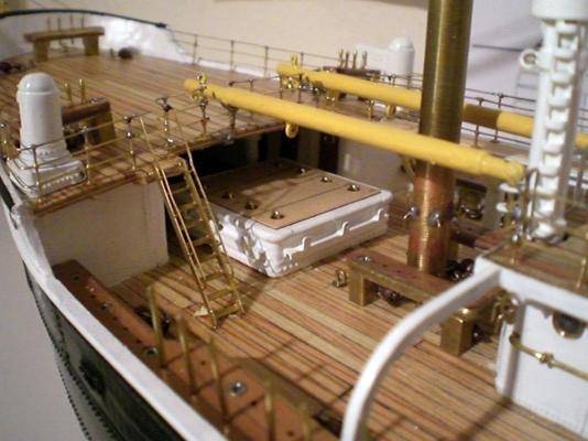
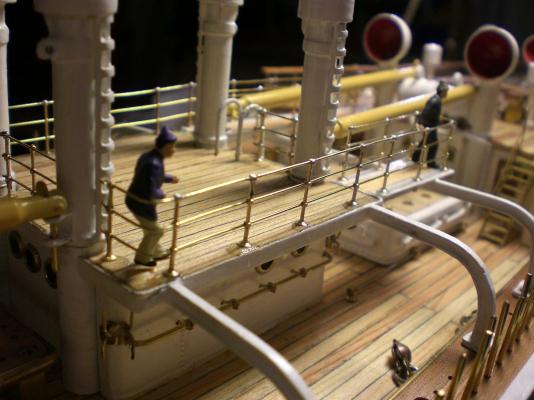
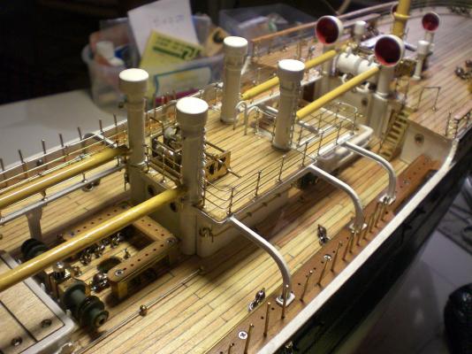
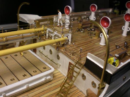
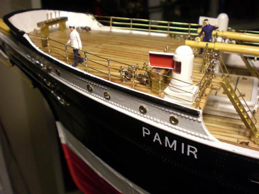
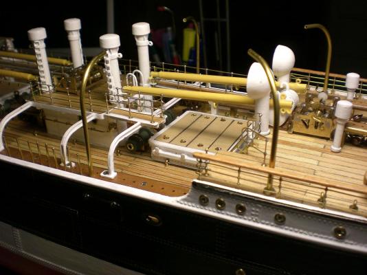
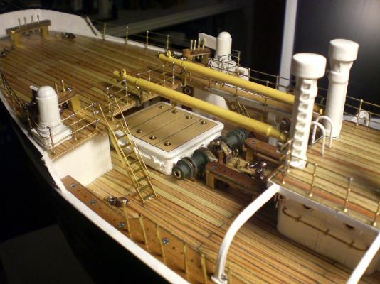
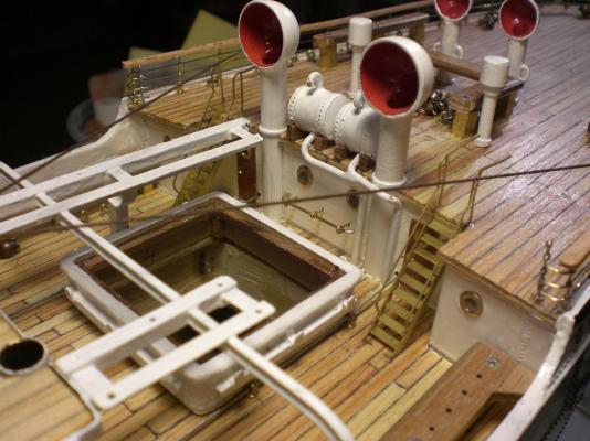
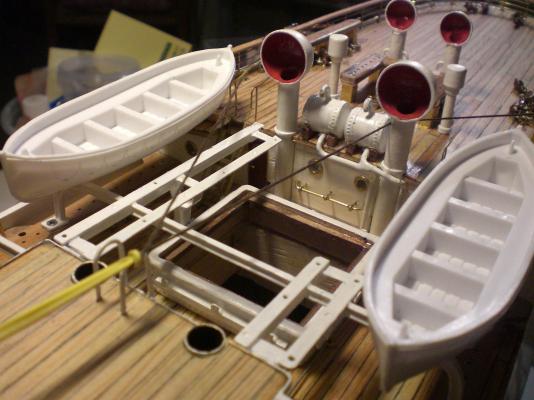
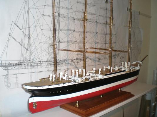
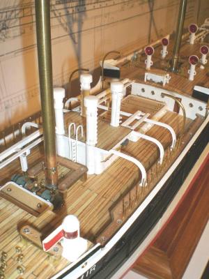
Build log part 27 overview aft welldeck checking with one of the 4 aft boat davits space positioning for wheel- and Chart-house as well as other deck housings on highdeck looking where to place lifevest Containment on aft boatstation spacing aft poopdeck housings the shipyard Management is quite happy with the progress so far again checking mast positions Forward welldeck Davits mounted port lavatory door on aft welldeck pig Kennels, port / starboard (for live pork) behind the forecastle bulkhead not fitted yet Build log part 28 to follow.... Nils


- 269 replies
-
- 16
-

-
Build log part 26 railings fixed to boat stations, catwalks and deckhousing decks overview of aft welldeck area, cargo derricks attached utmost time for mounting blocks around the mast area (no good Access afterwards) portside boatstation railing on compasplatform and stairs attached to railing forecastle railing and stairs foreward welldeck port boatstation aft welldeck port boatstation everything has found its place Build log part 27 to follow.... Nils


- 269 replies
-
- 12
-
-
Thank you Popeye Nils
-
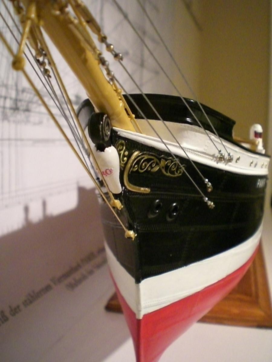
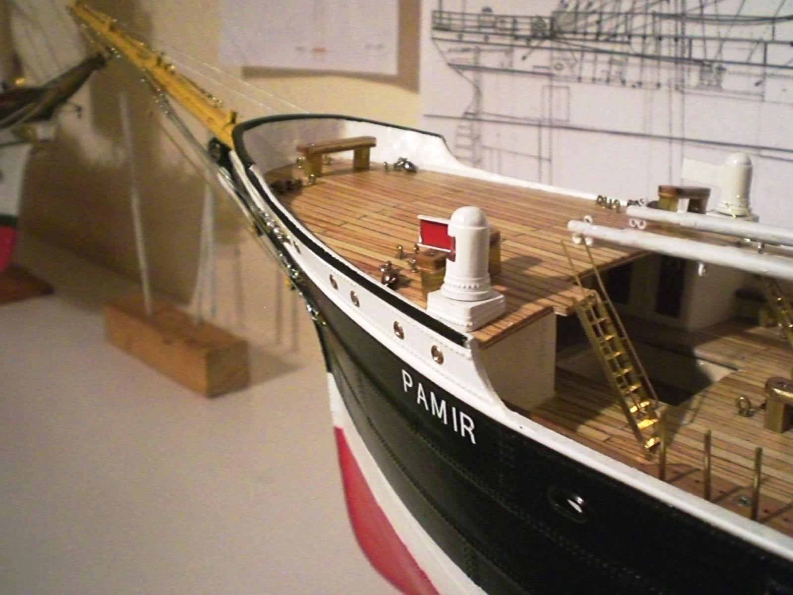
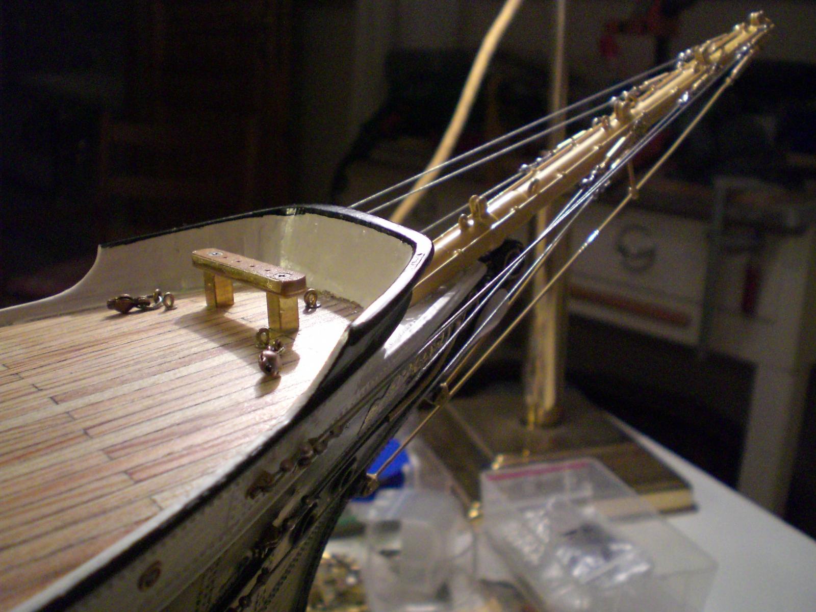
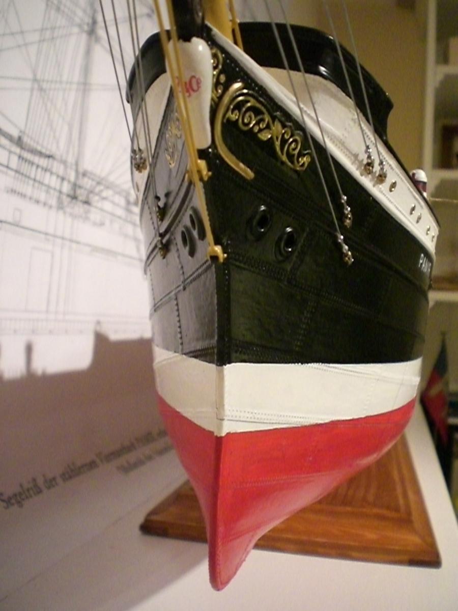
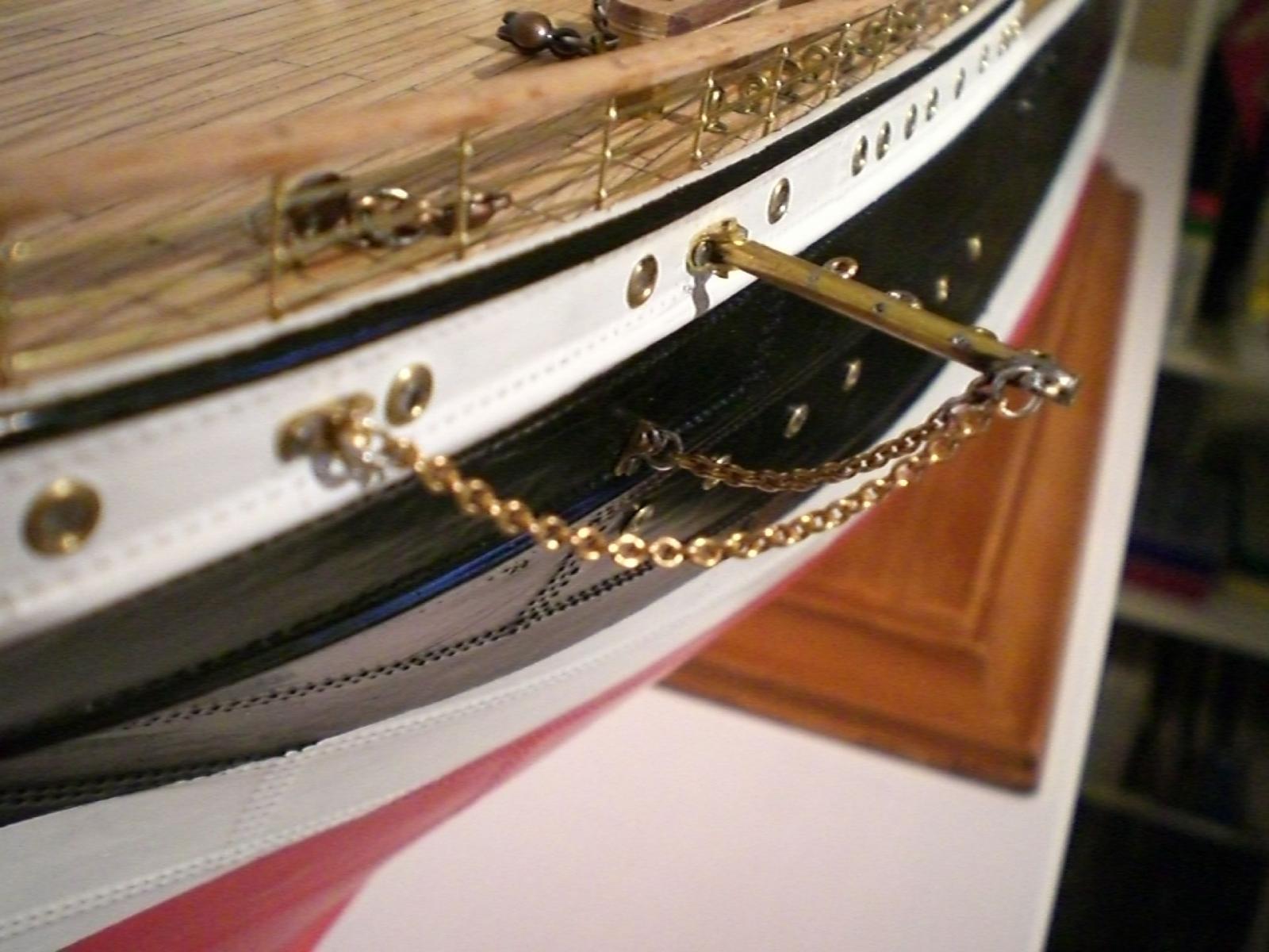
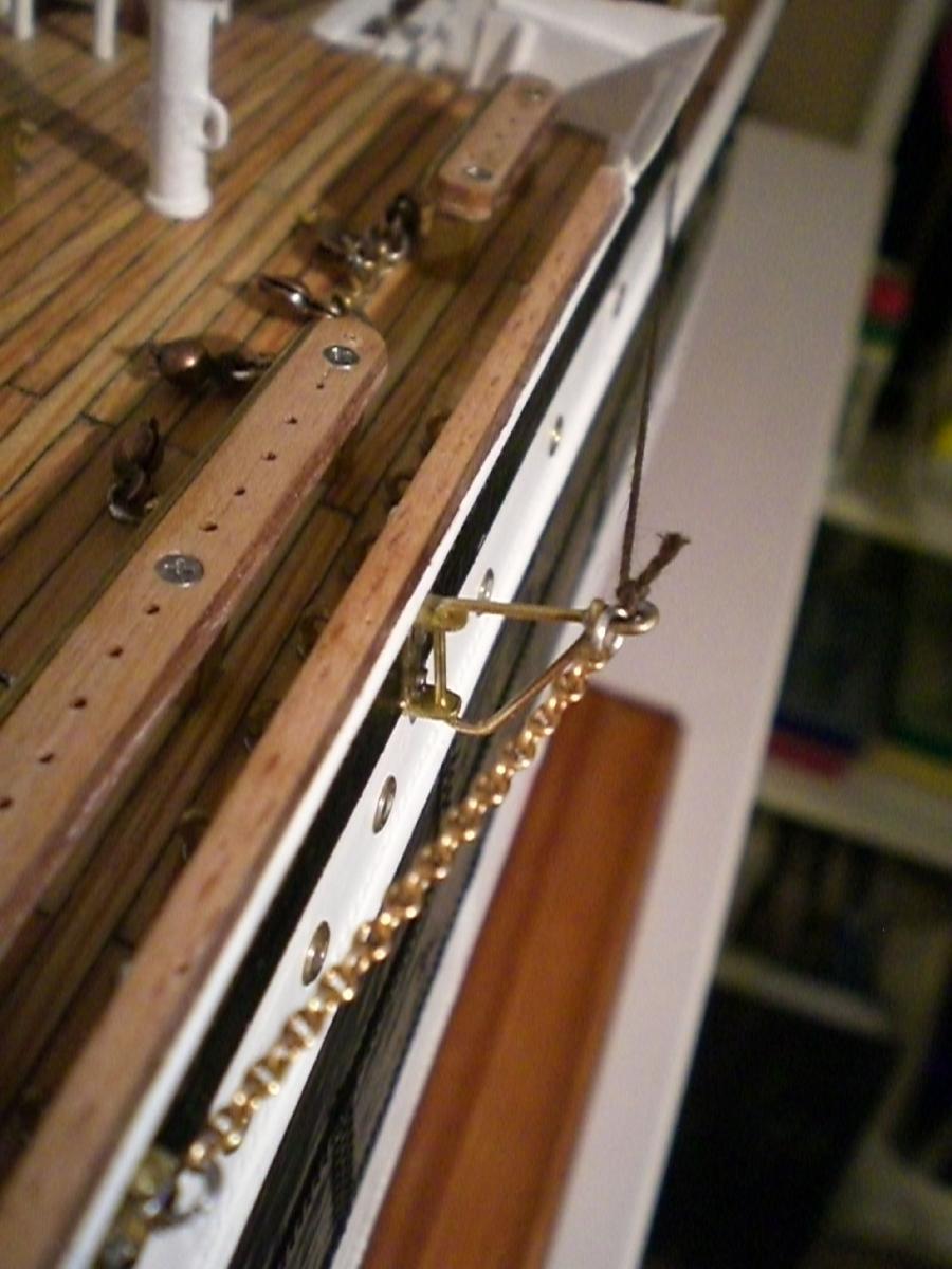
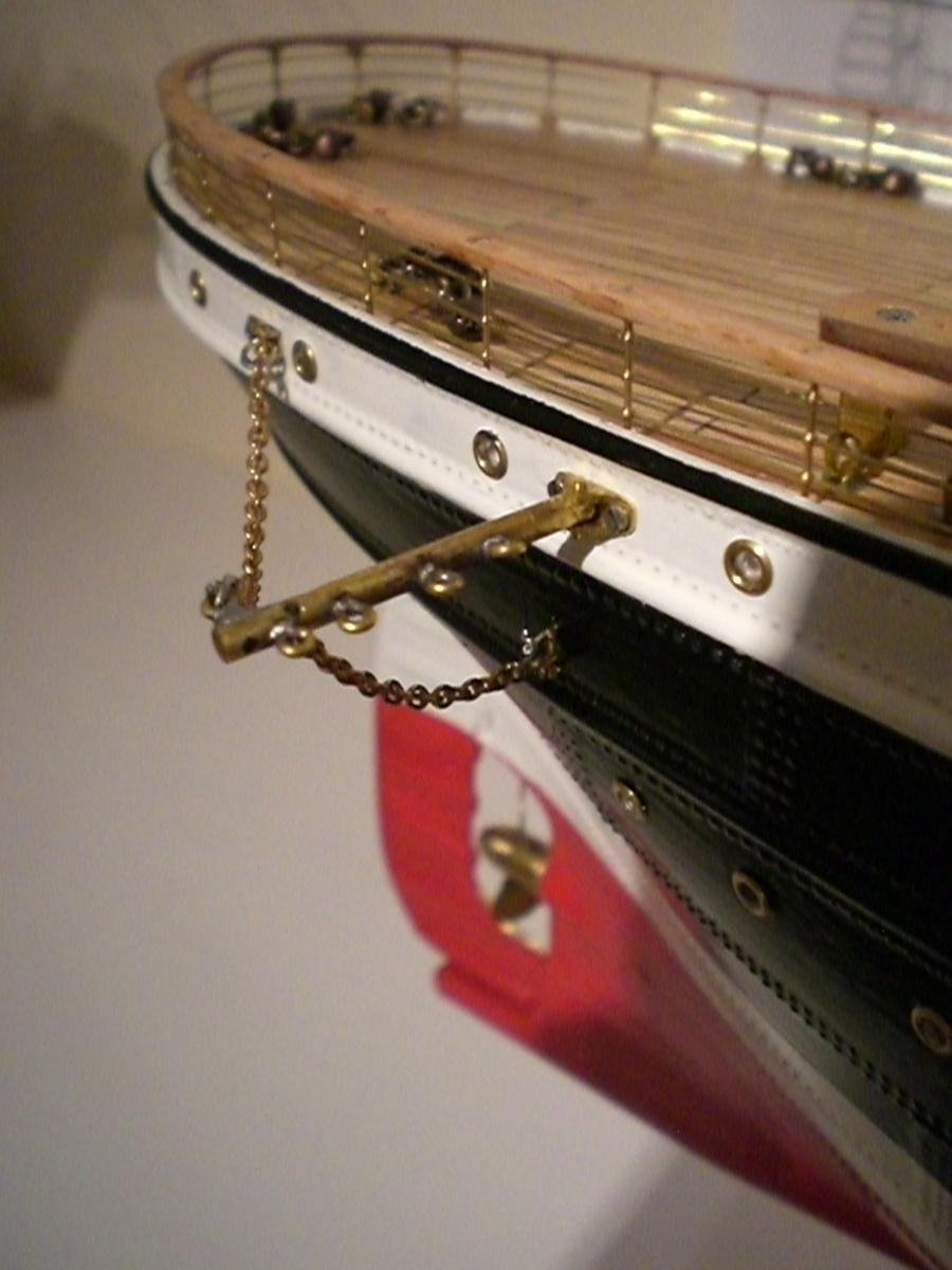
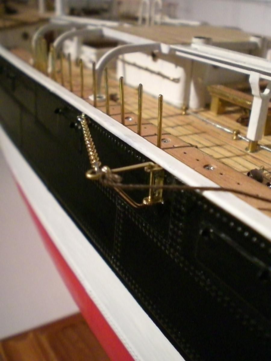
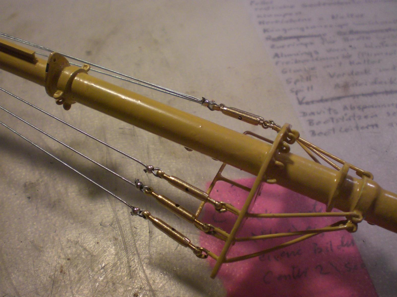
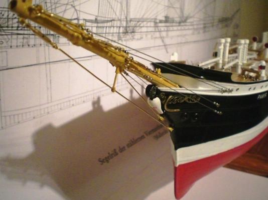
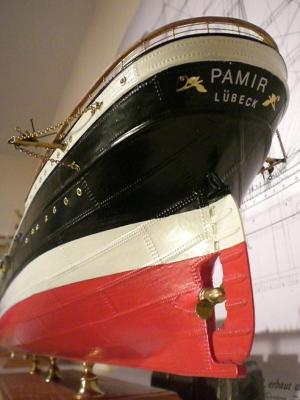
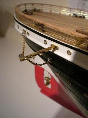
Build log part 25 poopdeck railing mounted, moved small vents away from the place where the brace winch goes to preliminary space check with the larger 2 ones of the 4 aft boats jib boom stays and bobstays attached Forward welldeck (primered) cargo derricks in Position check Stern view with poop railing forecastle railing not attached yet bow view at this stage Buildlog part 26 to follow.... Nils


- 269 replies
-
- 10
-
-
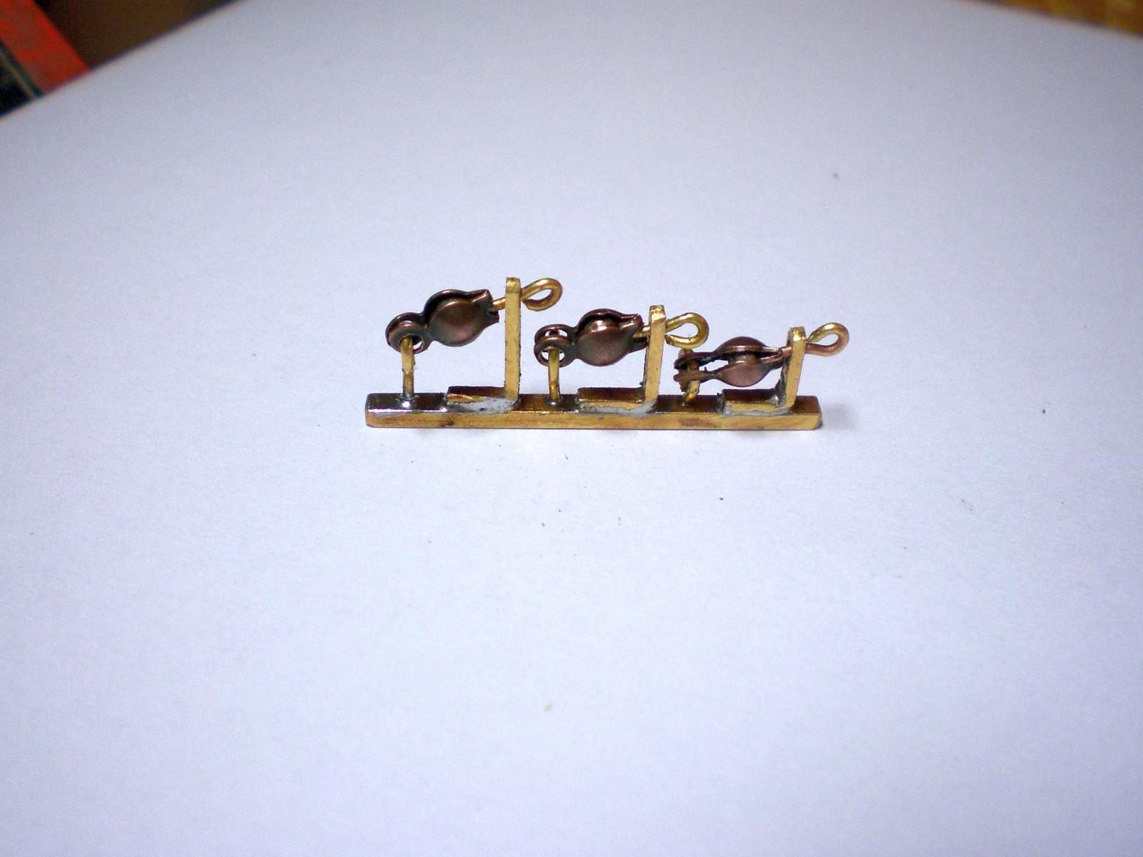
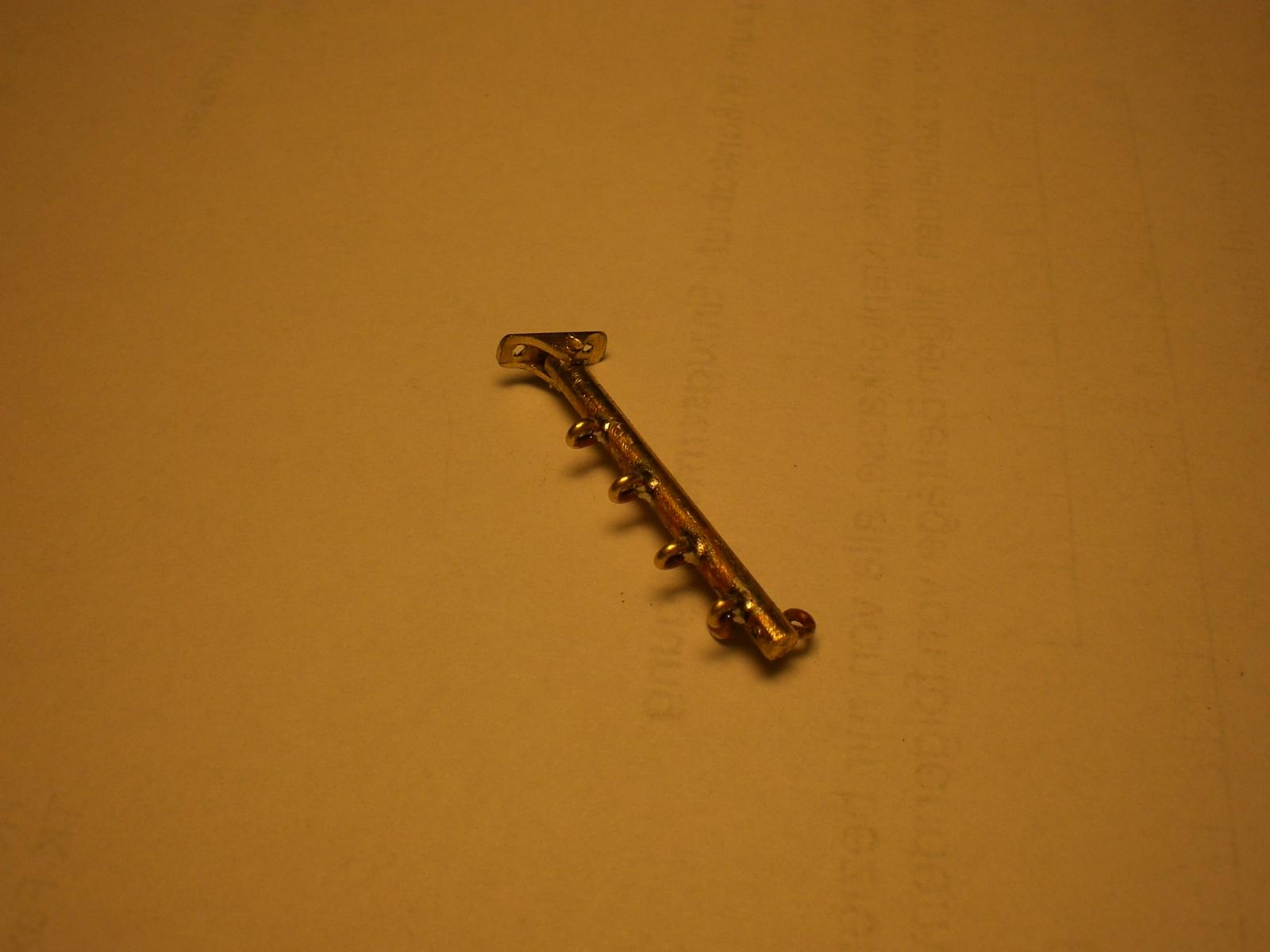
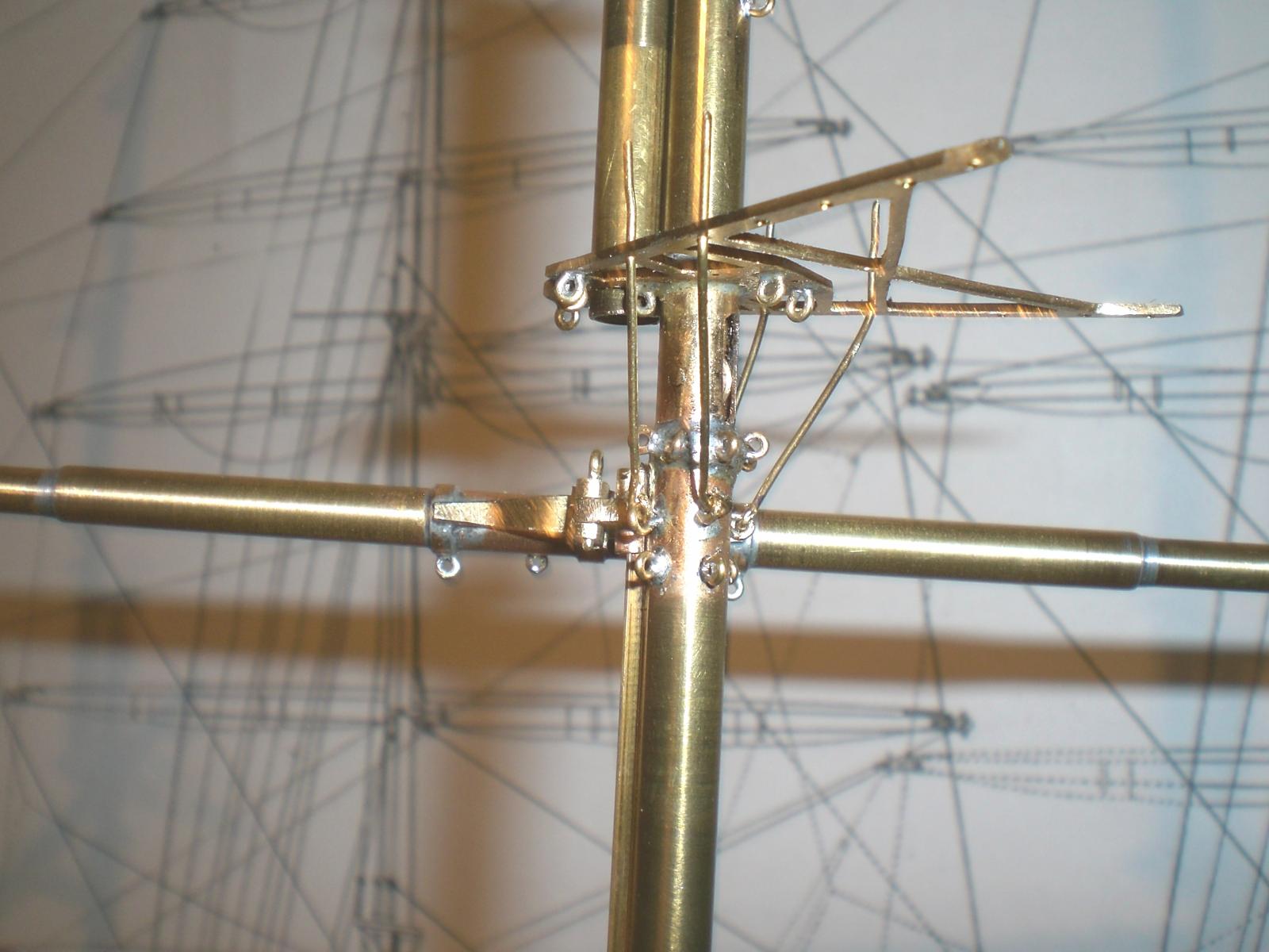
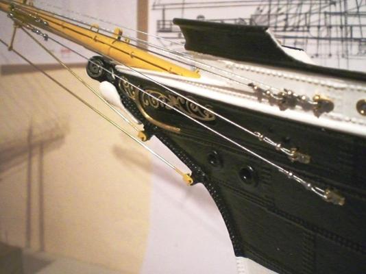
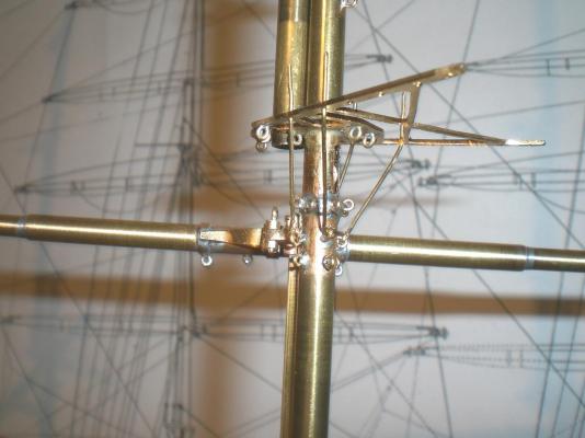
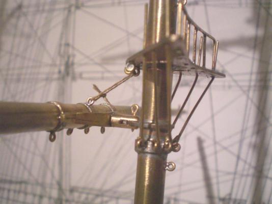
Build log part 24 cross checking mast angle, positions, hights, alignment masts go right through the decks into the "spine" above the keel, mentioned earlier in this build jib boom placed at an angle (horizontal of about 19° tripple block Arrangement for foremast brace Tackling, these two devices will be mounted to the highdeck bulwarks These two pics...., bracing tackle bumpkin for blocks and ropes for third mast bracing tack bracket for second mast mainsail bracing tackle bumpkin for blocks and ropes for third mast bracing tack bracket for second mast mainsail Build log part 25 to follow.... Nils


- 269 replies
-
- 14
-
-
Ken my experience is : sand the planking to smooth and step free condition sweep off the dust with a brush thorrowly and also by using a clean Cloth apply 2 coats of nitro based clear Wood primer, (Nitro Einlassgrund)that drys within 3 minutes leaving a dull smooth shiny but dense Wood surface. No sanding afterwards !!! That is the best surface base for applying the tape Nils
-
Yes Lou, i use a White coloured resin based primer (otherwise no propper paint adhesion) Nils
-
Yes Crackers its going to be the complete sunday suit of sails, nice Little pic. you posted... Nils
-
Thank you Nenad, yes the MSW is a wonderfull game of give and take, I`m glad if I can help anybody Nils
-
Bob, I am happy that you like this part of the rigging Nils
-
Thank you popeye Nils
-
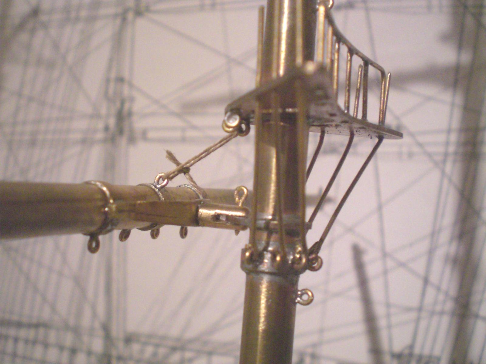
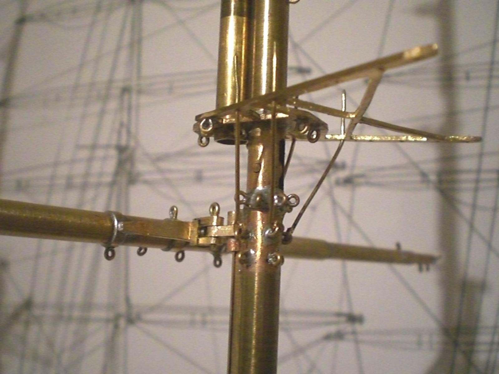
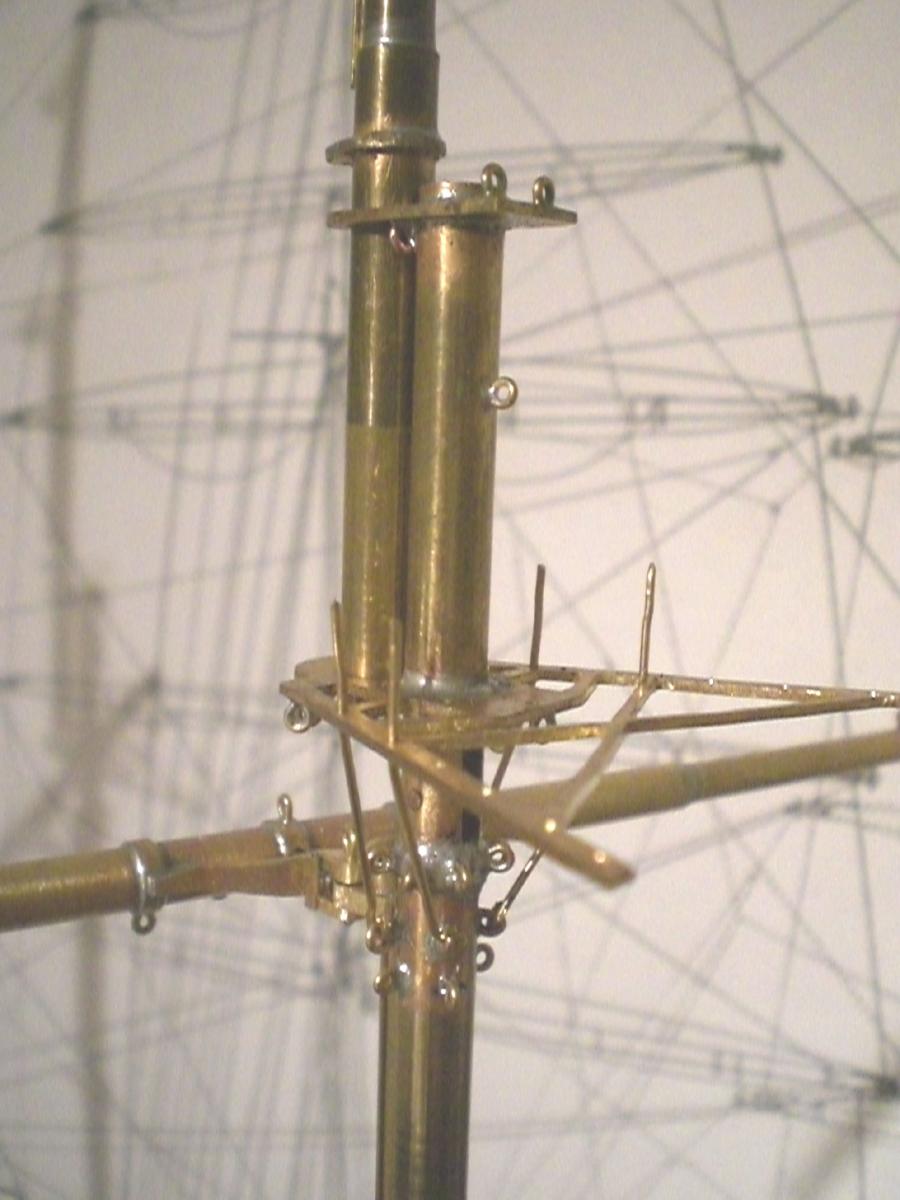
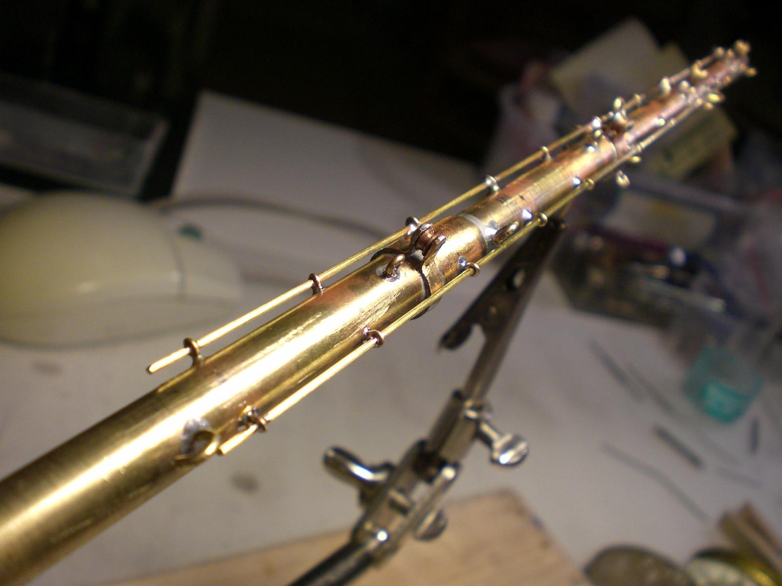
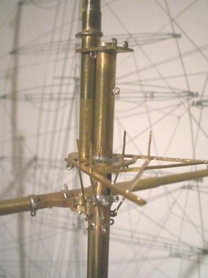
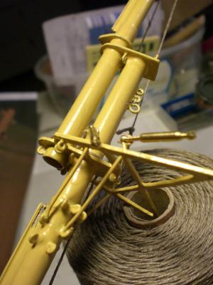
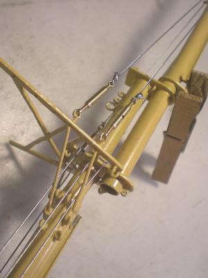
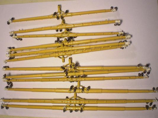
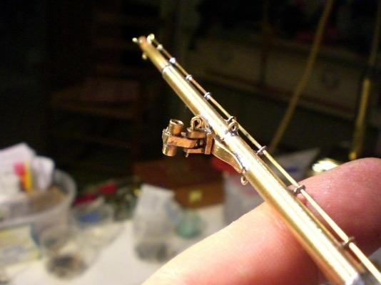
Build log part 23 some more impressions on the mast work soldering the jackstays to the jib boom some paint to the masts and beginning with the upper shrouds some of the Yards tackled with blocks Yard rack and bearing device Build log part 24 to follow..... Nils


-
Crackers, in general all the "running rigging" was of flexible rope. The "static rigging" like shrouds, stays backstays, Yard lifts, footropes,jib boom stays, the short stopps from Yard nock to the first bracing block, etc. were of wire Nils
-
Harvey, thank you for your appreciative words... I have a whole Shelf full of Pamir related books but for that one I shall be on watchout, Thanks for you tip Nils
-
Daniel, the poncewheel is selfmade from an old toothwheel from a mantel-clockwork and the handle of an old Paintbrush. If you like, you can refer to my buildlogfor for my steamship Heinrich Kayser at the end of part 2 therein (Topic: scratch built models in Progress) Trust that helps along, otherwise feel free to come through again, I`ll be glad to help Nils
-
Thank you John Nils
-
Bob, I thank you Nils