DONATION DRIVE - SUPPORT MSW - DO YOUR PART TO KEEP THIS GREAT FORUM GOING!
×


Mirabell61
-
Posts
7,410 -
Joined
-
Last visited
Content Type
Profiles
Forums
Gallery
Events
Everything posted by Mirabell61
-
 John, Thanks for your Input... when mentioning the load beams I meant cargo derricks, sorry for confusion..., and thanks for the correct term Nils
 -
yes, you should try it Bob, it saves many headaches and broken Planks.. Nils
-
Thank you bugra, stay tuned there are many more log parts to come... Nils
-
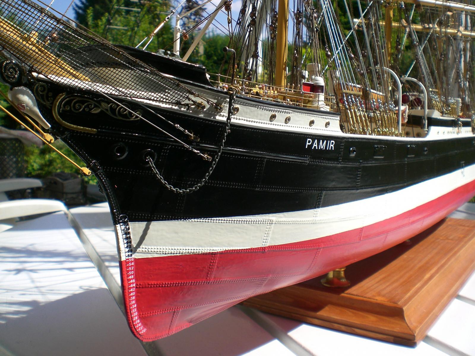
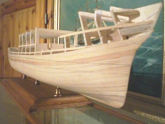
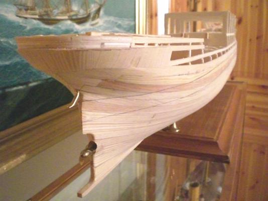
Hi Crackers, Thanks for your nice words, and yes, if this is the 1:150 Heller kit, it surely will be an ambitious model to complete, I`m not sure from the Picture if it is the Version before or after 1951 you are showing, it is difficult to make out. Let me use this ocasion for pointing out the differences after the Pamir had been changed at Howaldtswerke-Deutsche Werft in Kiel Major changes after 1951: - prolonged poopdeck - additional 2 deckhouses with attached 4 ventposts to each housing that also act as the pillar co lumes for the cargo derricks - 1000 PSi engine fitted - 2,5 meter dia. 2-blade Propeller fitted - modified rudder fitted - additional 2 boats and Davits mounted on foreward deck, set behind the foremast shrouds and back stays on skid type cradle s enabling slip backwards on skid under the Position of the foredeck Davits - three(of each 6-drum comprising) Jarvis bracing winches mounted, enabling easy bracing, to the f irst three lower Yards of the 3 mainmasts. The bracing rigging was changed accordingly - modified catwalks from poop to the high middeck and on to the forecastle deck, for speedy and dr y Crew movement in rough water These changes of corse required for space, so everything became more "crowded" on the decks, this also causing the 1:96 model to well place the changes.... If I have forgotten any Feature please feel free to advise... Nils
-
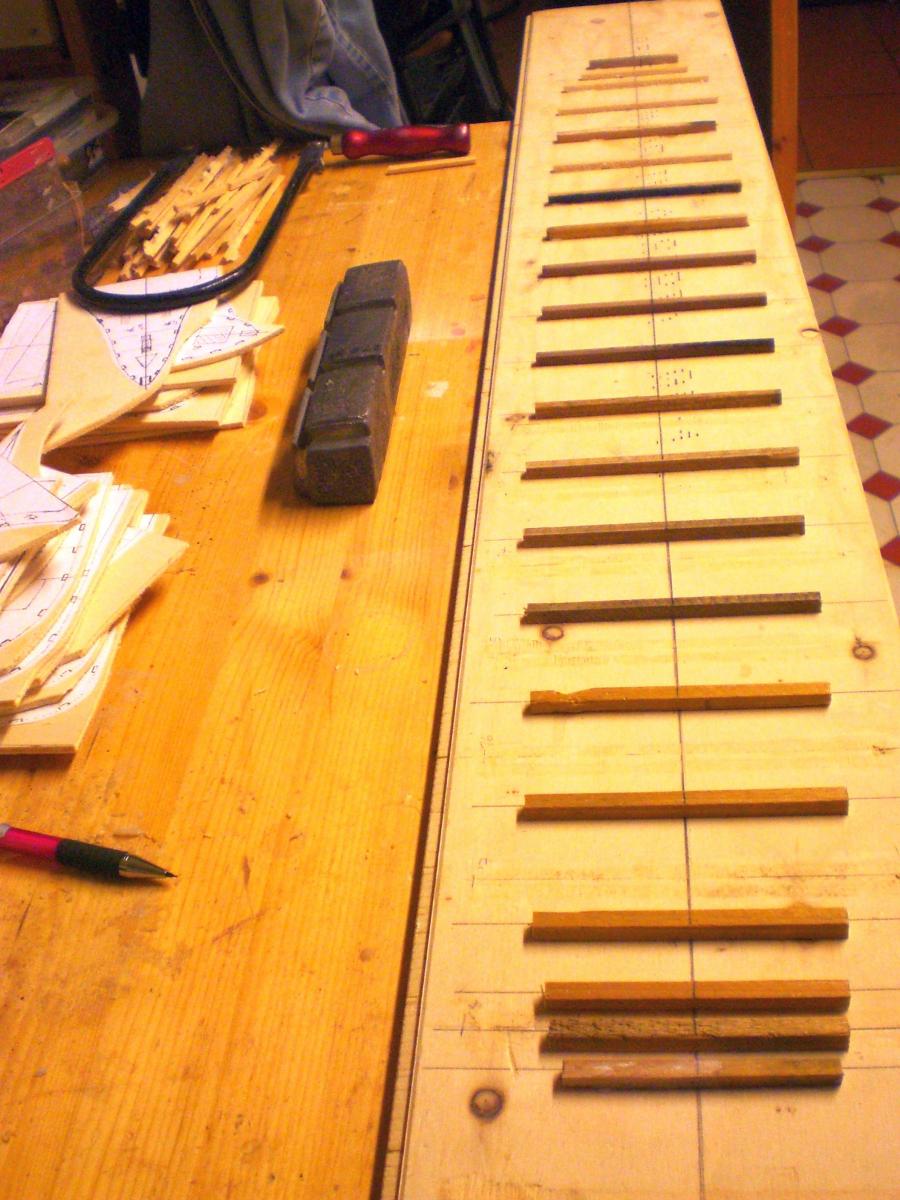
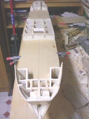
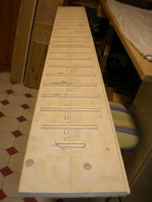
build log part 5 a good base for Fixing the poopdeck on same for the midship high deck, on the "keel-spine" the counternut for one standbolt can be seen bow bulwark planking also done vertical the Forward main deck reaches well under the upper forecastle deck Fitting vent tubes preliminary, to see if the frontside of poop bulkhead notches are adequate here again the hull lines clearly to be seen the decks are from 1,5 mm 4 layer aero plywood handscetch for scaled heights of belaying pin racks and bulwarks planking of poopdeck, with 1 x 3 mm Pitchpine (to be cleaned and sanded over later on) length several lots of cut pre-bundled and clamped deckplanks pencil-charcoaled at their thin- and face edges only Build log part 6 to follow.... Nils

- 269 replies
-
- 13
-

-
Thanks for this Information Bedford yes, I think the Pamir was wellknown in Australia an New Zealand.... Nils
-
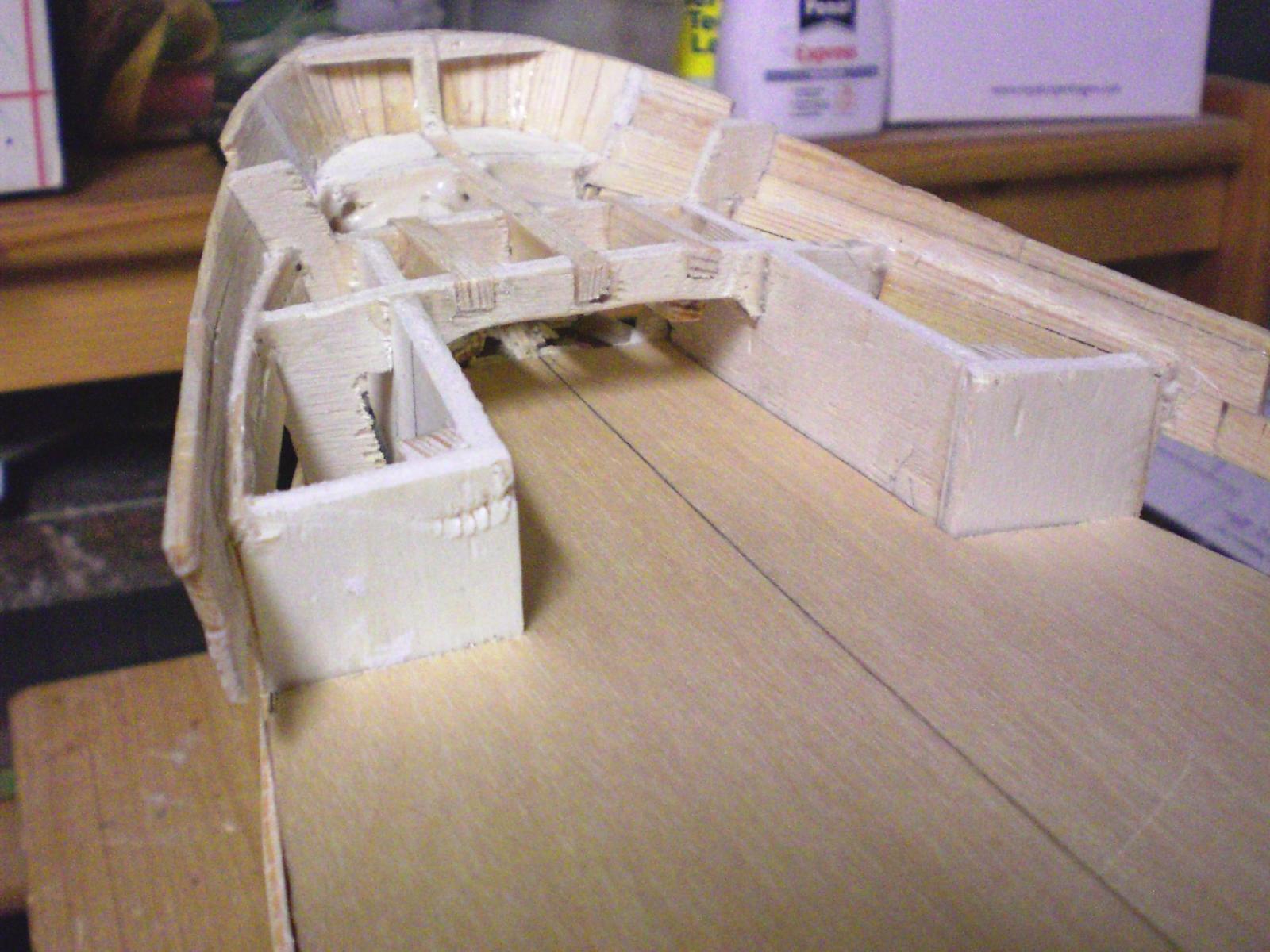
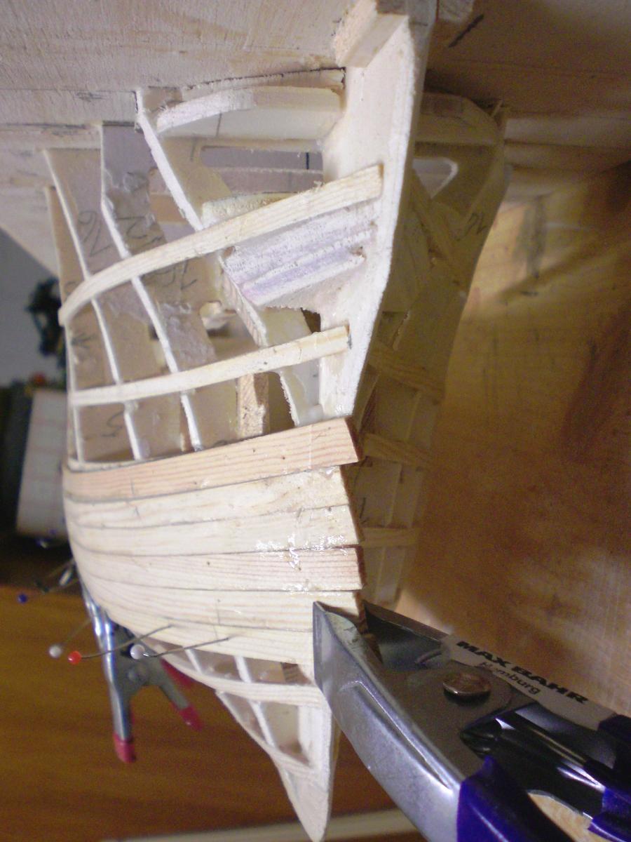
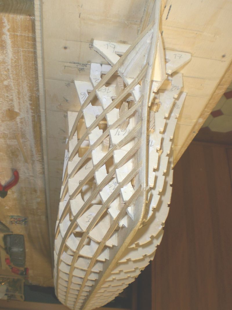
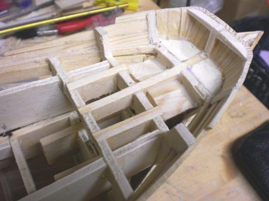
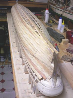
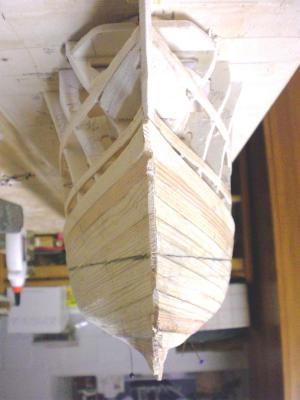
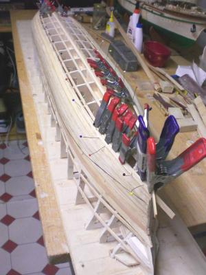
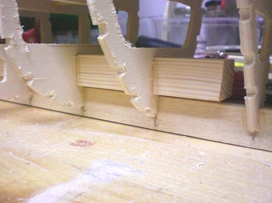
Build log part 4 3/4 planking done waterline with preliminary pencil marking vertical planking of spherical round upper Stern portion waiting for the glue to dry off this is a great Moment, the ship has been lifted off the baseplate for the first time, Hull sanded over, all Looks OK. Prop and shaft claddings as well as ruddershaft fitted meantime the stand with its three brass Posts has been made and fitted Planks just before the decklines left open for enabling Access underneath to the decks when they get mounted all bukhead heights brout to appropriate deck levels The decks are in preperation already... Build log part 5 to follow Nils


- 269 replies
-
- 18
-
-
Karl, yes I also remember, I was 10 years old and the newspapers spread the Happenings and the newsflashes right down to Capetown as well... Nils
-
You`re right John, but knowing that there are 8 sets of shrouds, all those stays and appr. 64 backstays all under spanned stress it really takes the strong one to be on the safe side Nils
-
well, I did my best Bob so Keep tuned..... Nils
-
Alexander, your build makes ones heart jump higher, this is absolutely on my wave,it is new to me for I joined in after MSW 1 went lost. Very well done mate !!! Nils
-
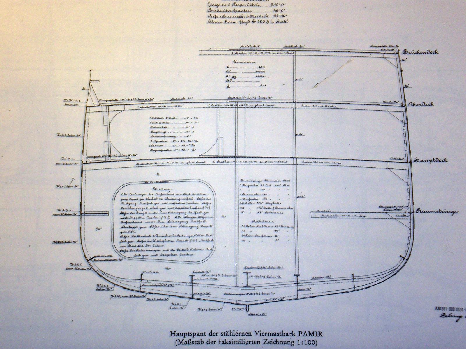
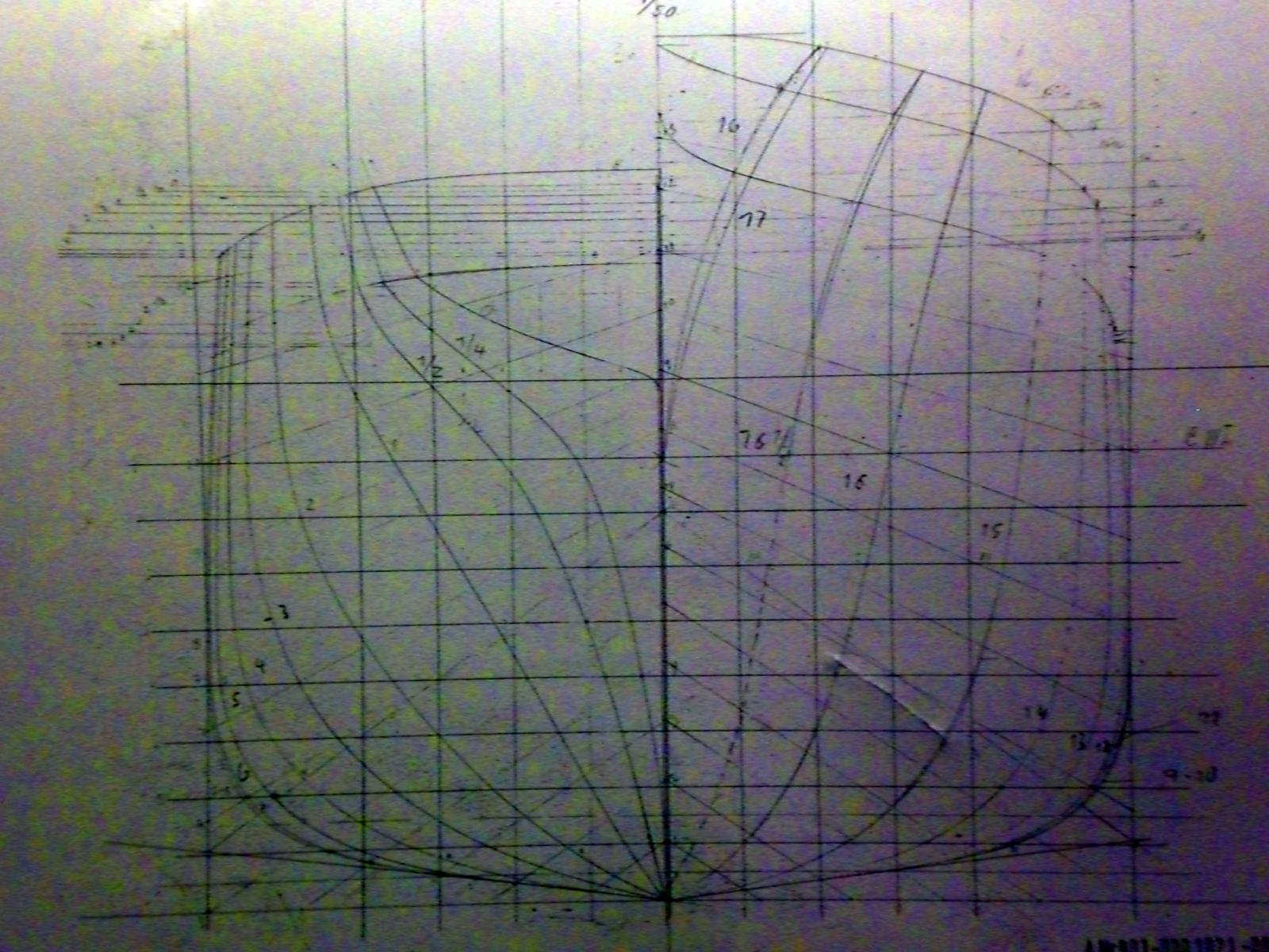
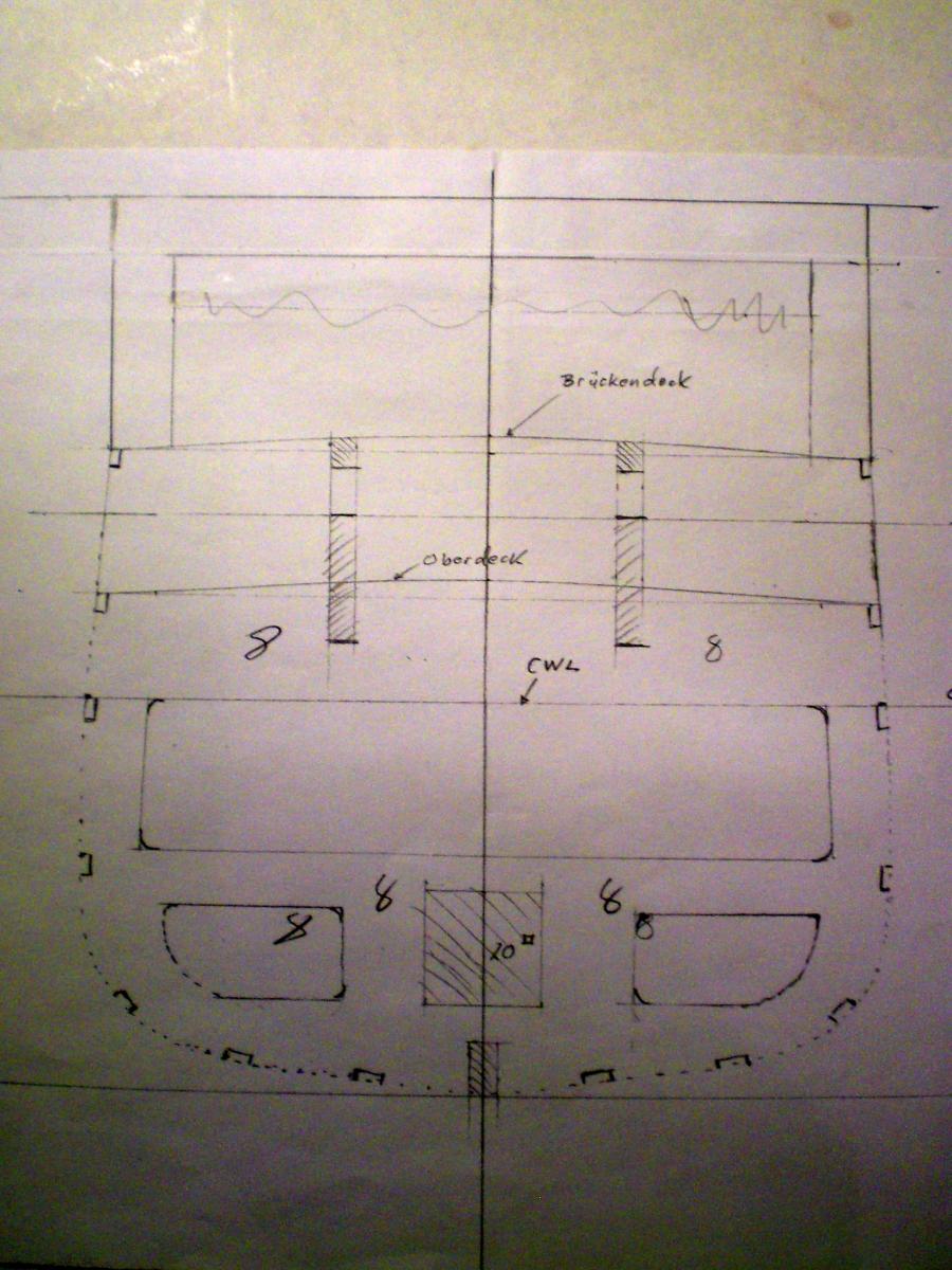
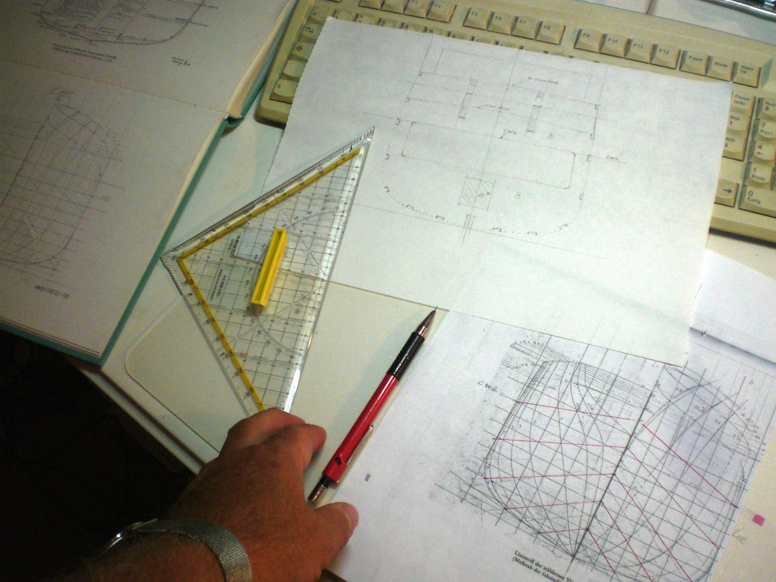
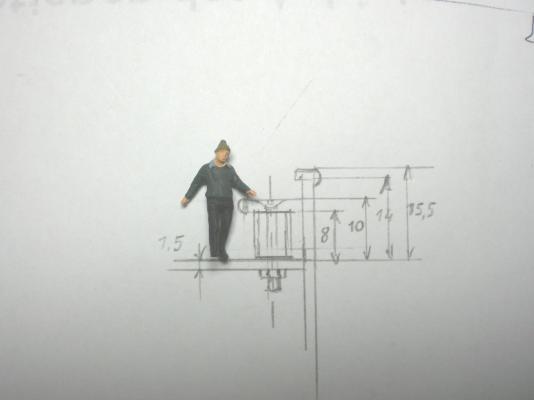
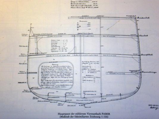
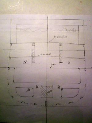
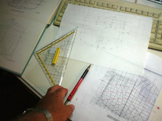
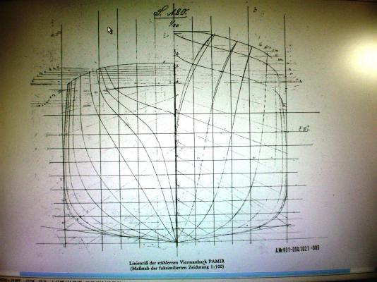
Nenad, the breadthwise curvature midships has 1,85 % height on midship centerline compared to the appropriate port / starboard deck edges (see enclosed Frame #8) For the longitudinal value you Need to use the Frame overview plan I am enclosing and check out the height of port / starboard deck edges. Projected into a side view you would get the % of that curvature Hope this is of help.... Nils midship mainframe use this plan for the longitudinal curvature, use CWL waterline as referance for distance to individual deck edges These curvatures I used for main decks and mid upper deck

-
Lou thank you I`m happy that this meets your interest Nils
-
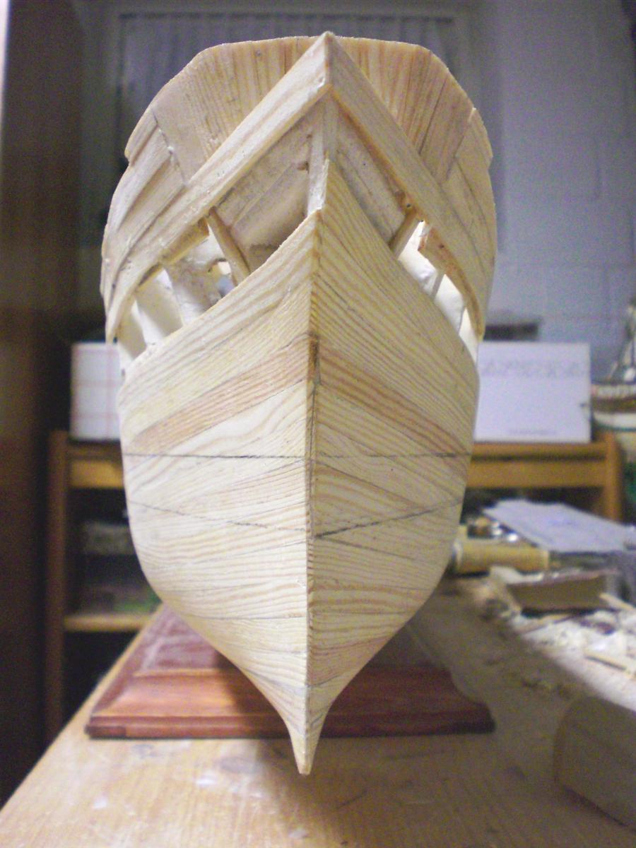
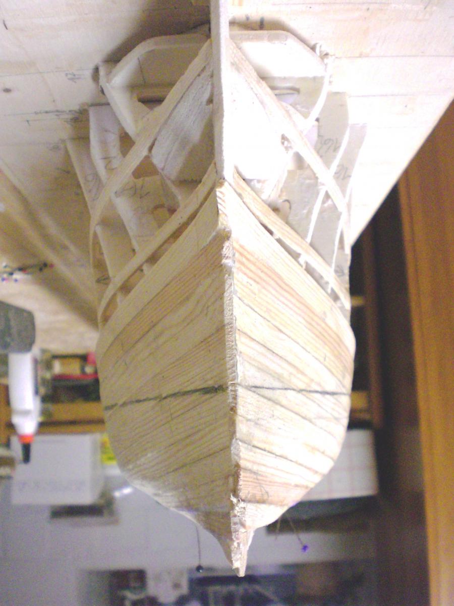
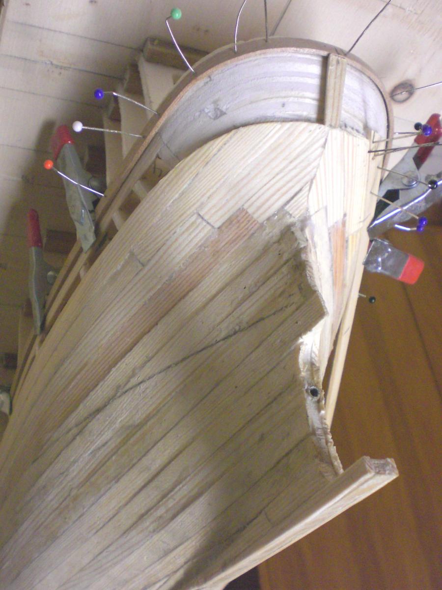
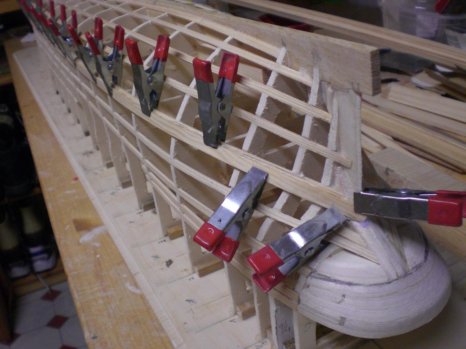
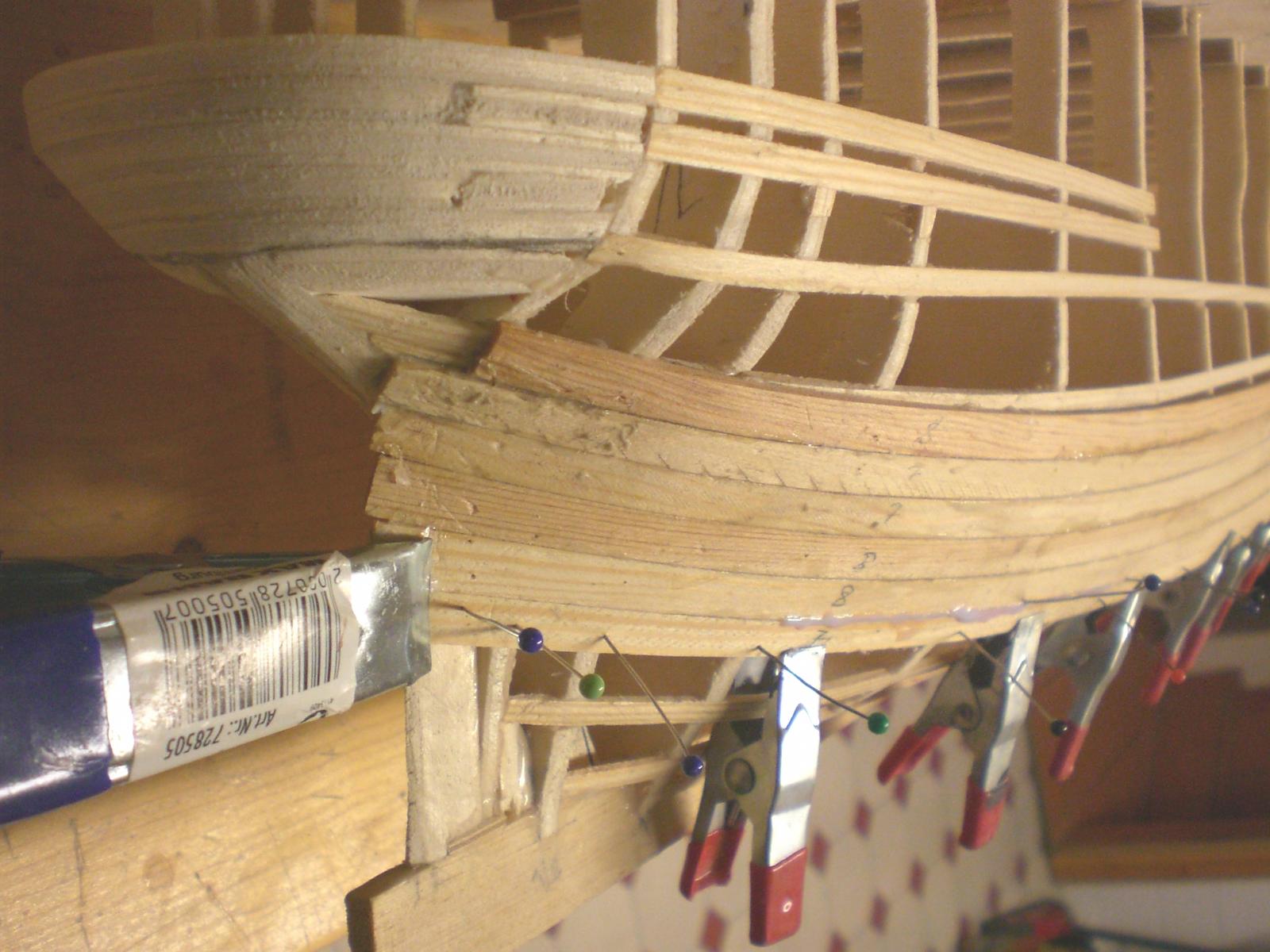
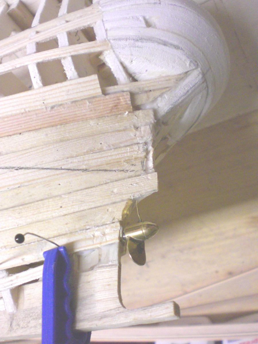
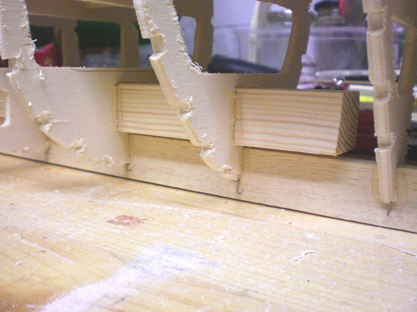
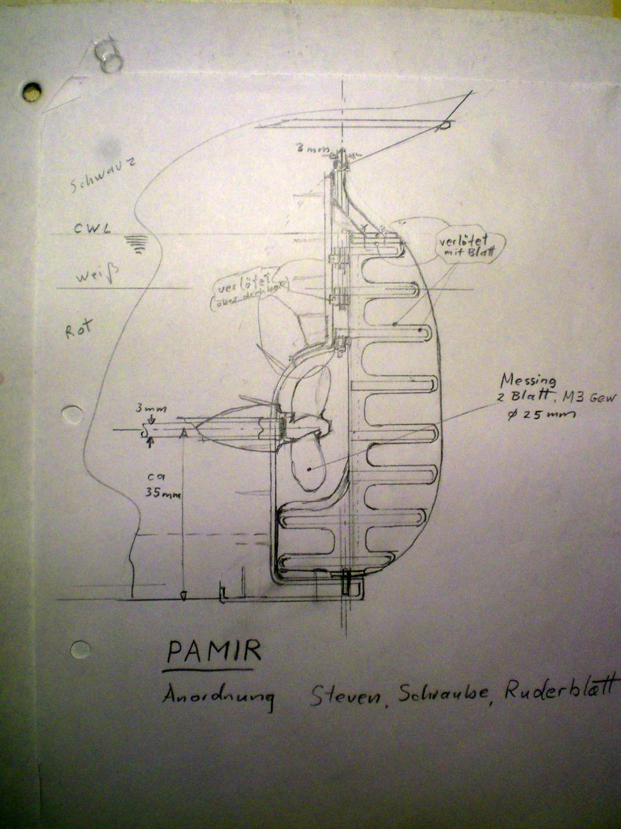
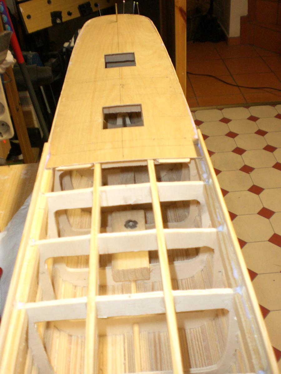
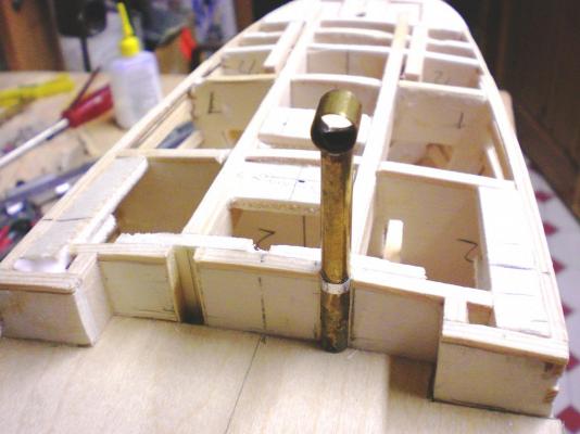
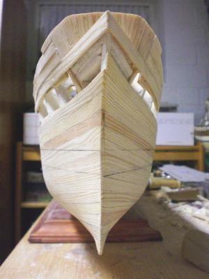
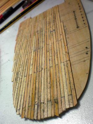
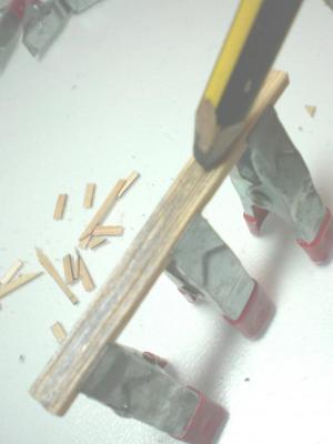
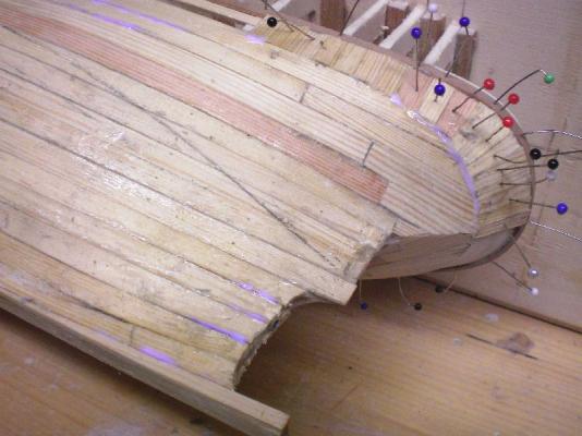
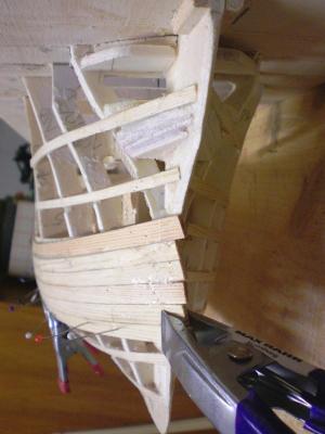
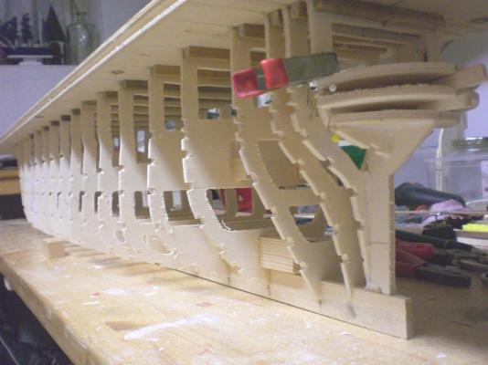
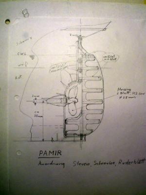
build log part 3 am satisfied with the result so far making thoughts about prop outcut and rudder blade Arrangement, corresponding to one of the various changes after 1951 For manouvering in Harbor Areas, in South American ond other bay Locations, shallow Waters, and in lack of wind, a 1000 PSi Motor had been built in, as well as a 2,5 m dia 2-blade Propeller. The other Major changes after 1951 I shall Point out later on the coming planking will be so much easier if the stringers can be used as Counterparts to fasten the clamps. These stringers also give enormous strength to the planking itsself all well under way now here Comes the first plank (pine as Long as the hull 2 x 10 mm)for single layer planking. I cut These Planks myself out of fine structure boards from the crafters. This hull shall also be plated later, so the 2mm thick planking provides sufficient thickness for smoothing down the outer surface well enough for the plating thats partiall enough for the starboard side, pull up the port side planking now.... same Status from bow view both sides planking is heading for the keel Little propshaft mounted and 2-blade Propeller fixed (M3 thread) this is one of the three foreseen standbolts, because this weakens the keel there have been wooden reinforcement claddings fixed to it from both sides within the hull Build log part 4 to follow.... Nils


- 269 replies
-
- 16
-
-
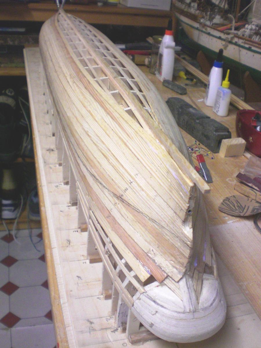
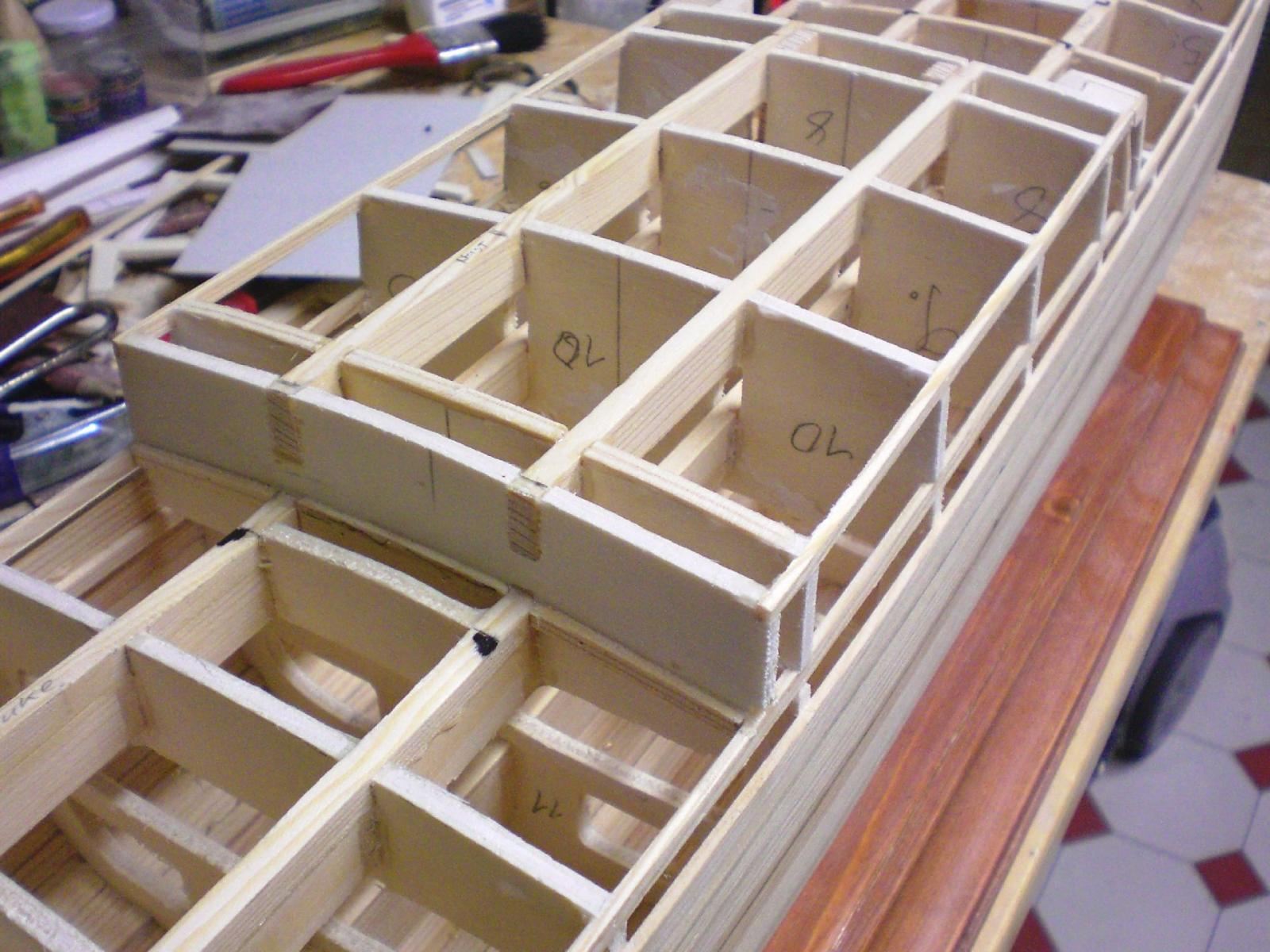
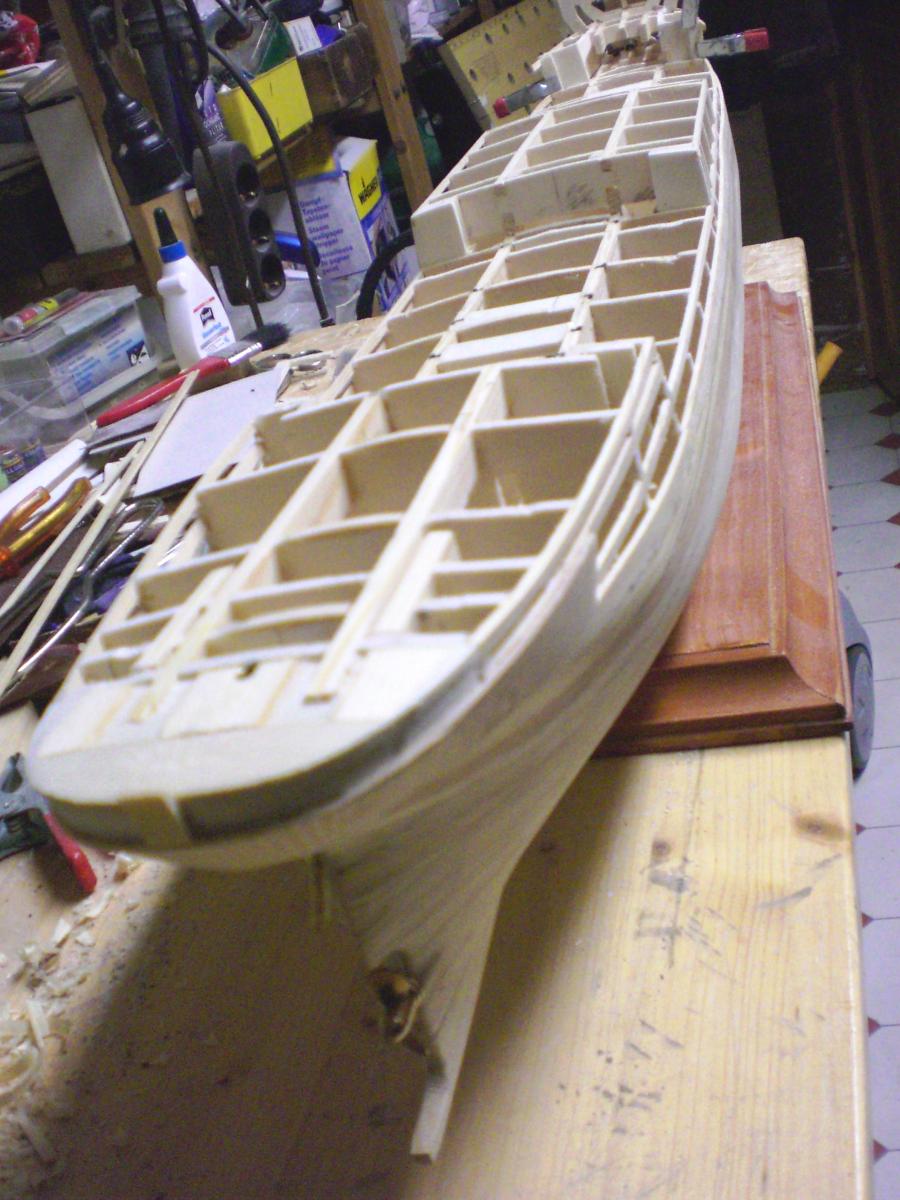
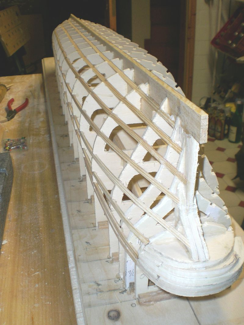
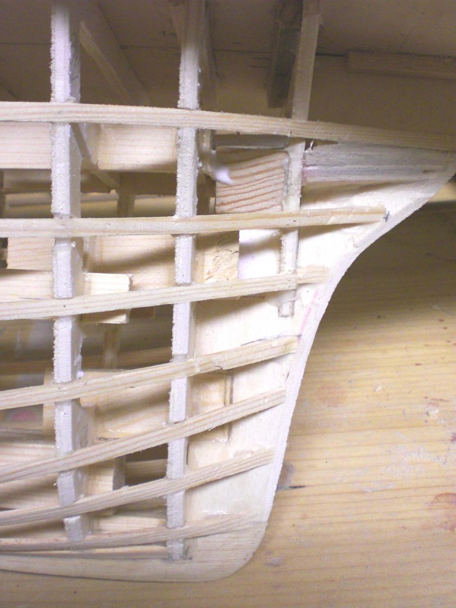
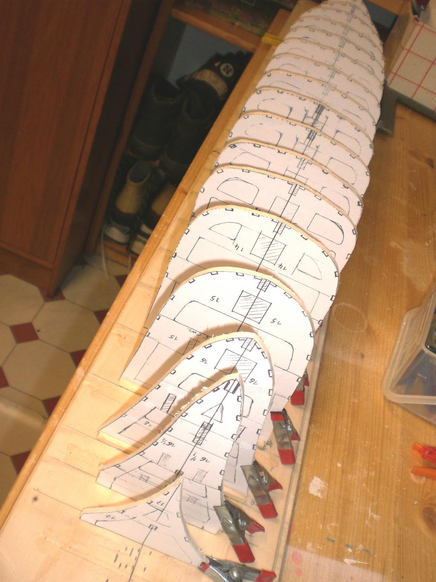
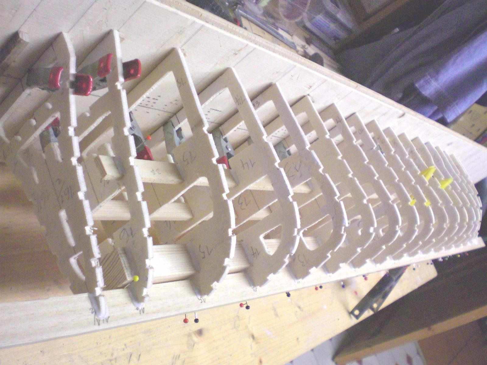
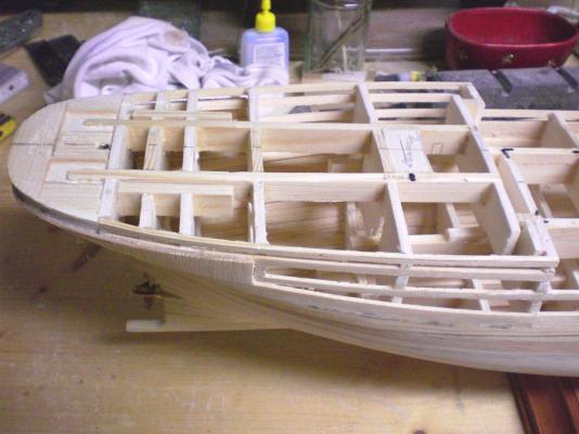
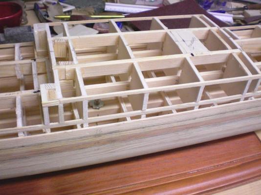
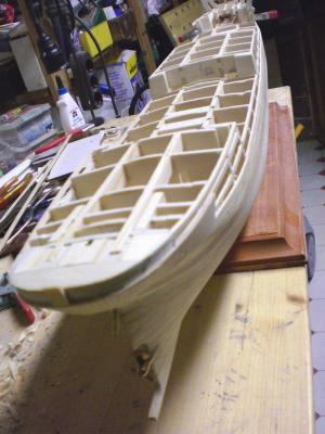
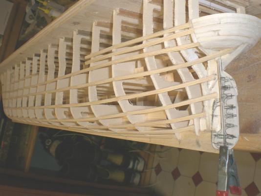
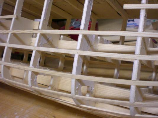
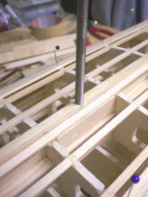
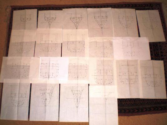
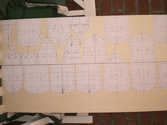
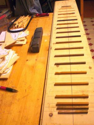
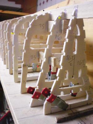
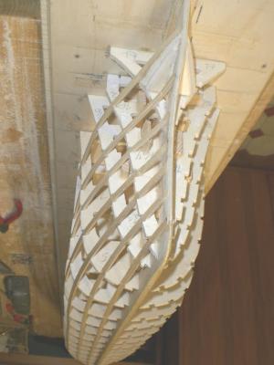
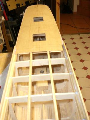
Build log part 2 working out and drawing the individual Frames in order to suit this build each Frame gets its own 1:1 drawing on paper rough cut out of the paper and fix on 4 or 5 mm thick plywood an obligatory base plate is set up to Keep all in alignment and to get (and keep) the keelline straight during the further build cut out Frames in preliminary set up, to see if all Frames are straking well cross check, yes it Looks like Pamirs lines of the early hull the model is being built keelside up, the Frames complete cut out, and the notches for the stringers done all looks well so far due to the fix on the baseplate all frames bear Surplus height, to bring (only interim, will be cut to suit later on)to the same level like a strong man Needs a strong Backbone, I have arranged for a "spine" 20 x 20 mm square beam to reinforce the hull for taking on the induced tensile stresses of all the stay and shrouds spanning, working on the hull later on. I never regretted to do this... well under way now, the stringers as well as the ships lines clearly to be seen now Build log part 3 to follow... Nils


- 269 replies
-
- 21
-
-
Well the horse had just been saddled by now... but thanks for yor words B.E. The pics shall probably beginn tomorrow and the following... Nils
-
Danny are you sure you finish daily before midnight, it somehow reminds me of Cindarella... Cheers Nils
-
I am quite happy with this construction John, it is also affordable Nils
-
Thanks John, I trust it is the first Pamir on this Forum, or was there one in the lost MSW 1 ? Nils
-
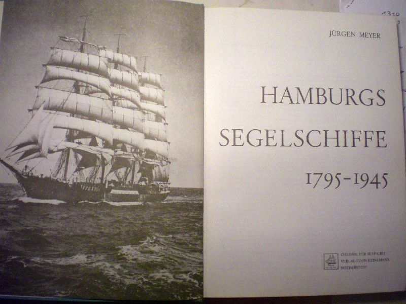
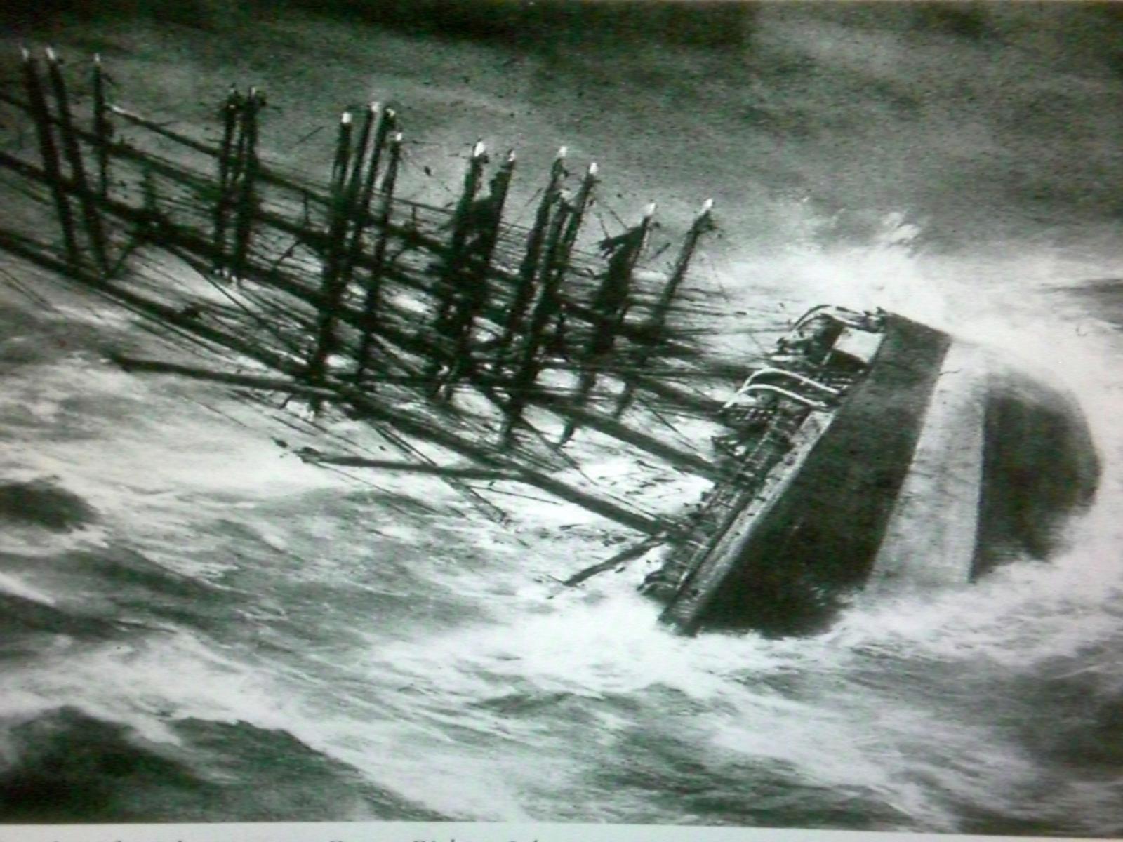
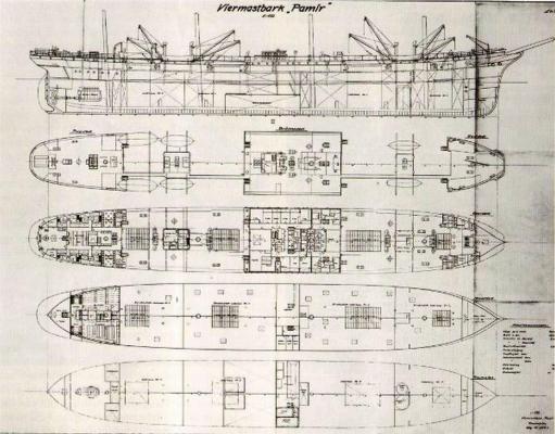
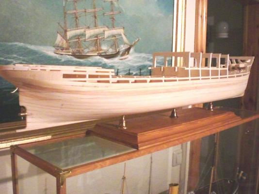
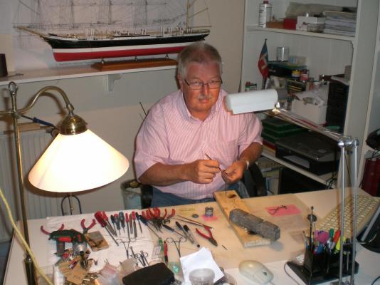
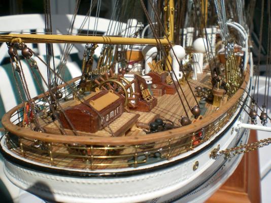
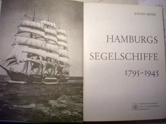
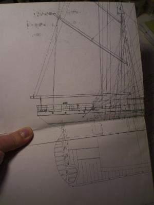
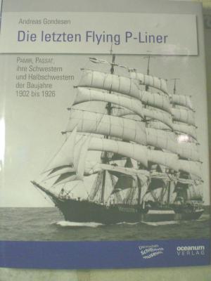
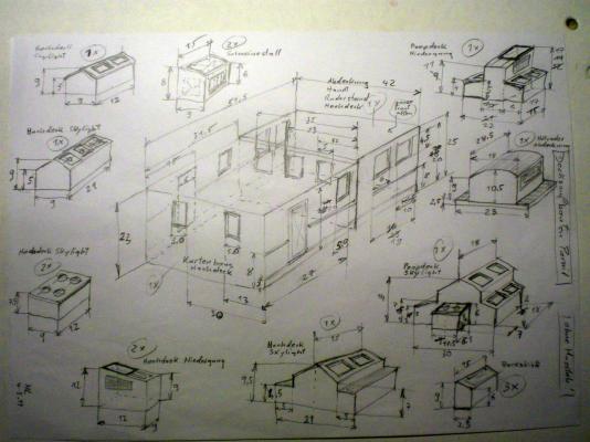
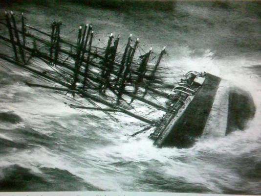
Sailing ship, fourmast-barque PAMIR in scale 1:96 Introduction to this build log, by Nils Langemann For modeling one of the famous “Flying P-Liners” of the last century, my choice fell on the PAMIR because that ship probably would be supported with most available information one can get in the appropriate media. Much has been written about the various owners, the crews,the routes, etc, and all this illustrated on the web, in literature, reports, photos, paintings and models in all qualities and scales, without here considering many various very good moulded plastic kit models. Most of all was reported about the tragic loss in Sept. 1957 when the hurricane “Carrie” called for its tribute. 80 of 86 crew members, mostly young men, lost their lives after their ship had finally capsized and sank within minutes, southwest of the Azores islands of the Atlantic, this causing the to date largest and most intensive post WW2 international coordinated search and rescue operation in the civil marine history. Trust the older MSW members still remember the news-clips and film reports of the 6 wounded roughbeaten survivers and their pictures as they told their story, after being rescued from their broken lifeboat wreck-hulks and after several days ongoing struggle for life. Most of the available plans for modeling the 1905 at Blohm an Voss built and launched Pamir, as well as many models exhibited in worldwide museums show the Pamir in all versions as she looked like before 1951, several changes in paint and slight modifications, acc. To the owner and nations and to suit its owners cooperate identity appeal had been made. I was looking for an authentic plan of the version after the major changes at the Howaltswerke- Deutsche Werft, Kiel in northern Germany in years 1951 /1952, and after which the ship was under the Hamburg based subsiduary of shipping company Zerssen & Co, whereby the homeport was Lübeck. A couple of german shipping companies founded an association that together with Zerssen as the ship relevant managing part, enabled the training of young civil nautical and sailor-handcraft in a win-win situation for both trainees and shipping companies. The old well known Laeisz colour of the P-liners had been chosen again, and the ship, still being a trade cargo vessel under sails routed to South American ports around the Cape Hoorn performed many trips. At the same time the Passat, (today still afloat as Museumship in Travemünde near Lübeck, Germany) was also changed and appointed for same further activities. The plan of performed changes was available and purchased from the Howaltswerke shipyard, and for the Frame/ Bulkhead plan I found authentic original Blohm and Voss drawings in a book of Hamburgs sailing ships 1795-1945, Author Jürgen Meyer. This model took me two years to build, and it is comprising about 1950 manhours modeling. More about design, preparing for the build, construction as well as information on the model will be given along with the Build log sequences as they are posted…. The already completed model 1:96, length 119,5 cm, can be viewed in my album, topic “Gallery of completed scratch built models”, Pamir 4-mast barque version as 1957 For all that also love these wonderfull squarerigger tallships, enjyoy and stay tuned to the build log…. Nils I ca`nt realy say today how many log-parts in total it will take, it depends on how much interest the fellow MSW members shall have as to the extension of the individual build sequences. If the interest should be like it was with the Heinrich Kayser build log, it probably would be the "whole program" Nils here we go.... Build log part 1 I am lucky to have my own hobby-room office These are pics of the proud and sturdy built Pamir which hundreds of nautic Trainees may have in good rememberance in Sept 1957 came the shocking flash-News of the foundering of the ship, and also over the to date greatest post WW2 search and rescue Operation in civil marine history. This frightning realistic pencil drawing by Artist Franz Richter Johnsen I feel is so emotional touching. It is showing the Pamir in its agony just before capsizing (masts down) and thereafter to sink within minutes. That was an indication that the hull must have been broken, otherwise it would certainly have stayed afloat some hours, even in that illfated position, and the S&R Groups could have made her out better I was often asked what plan-drawings I had for doing this project, and would like to bring attention to two very informative books... (I am in no way associated with the authors or its Distribution) There is first : Hamburgs Segelschiffe 1795-1945, author, Jürgen Meyer, can be found preferably at book antiquariates it contains amoungst many other beautiful Tallships, copies of original Blohm + Voss Pamir plans. The Basic Frame / bulkheadplan was used for my model There is second : a relatively new publication, Die Letzten Flying P-liner, by Andreas Gondesen, who I consider as one of the best knowledgeable authors of the famous P-Liners, their History, as well as pointing out the differences between Pamirs several "Sister" ships, hardly known to the public. The great benefit of this book is the wonderful accurate detailed large plan in poster Formate of the Pamir in scale 1:100, that comes along included with the publication. (it is representing the Version before 1951 though), but never the less a must for Pamir modelers outcut from Gondesens Pamir plan many handscetches had been made by myself, here only some examples for those of you who know how good the extruded quality and precision of the Heller plastic Pamir kit and its moulds are in scale 1:150, I took the measurements for the various deckhousings from a wrecked plastic torso I found in a bin, and magnified these ratings to scale 1:96 Whoever does not know the Heller kit, please be advised, it is representing the precise Pamir Version of 1951 /1952 in top quality, but on a high skill Level Together with a plan comprising all the changes to the Pamir from Howaltswerke Deutsche Werft in Kiel, I was ready to get my project under steam at last...... Build log part 2 to follow...

- 269 replies
-
- 19
-
-
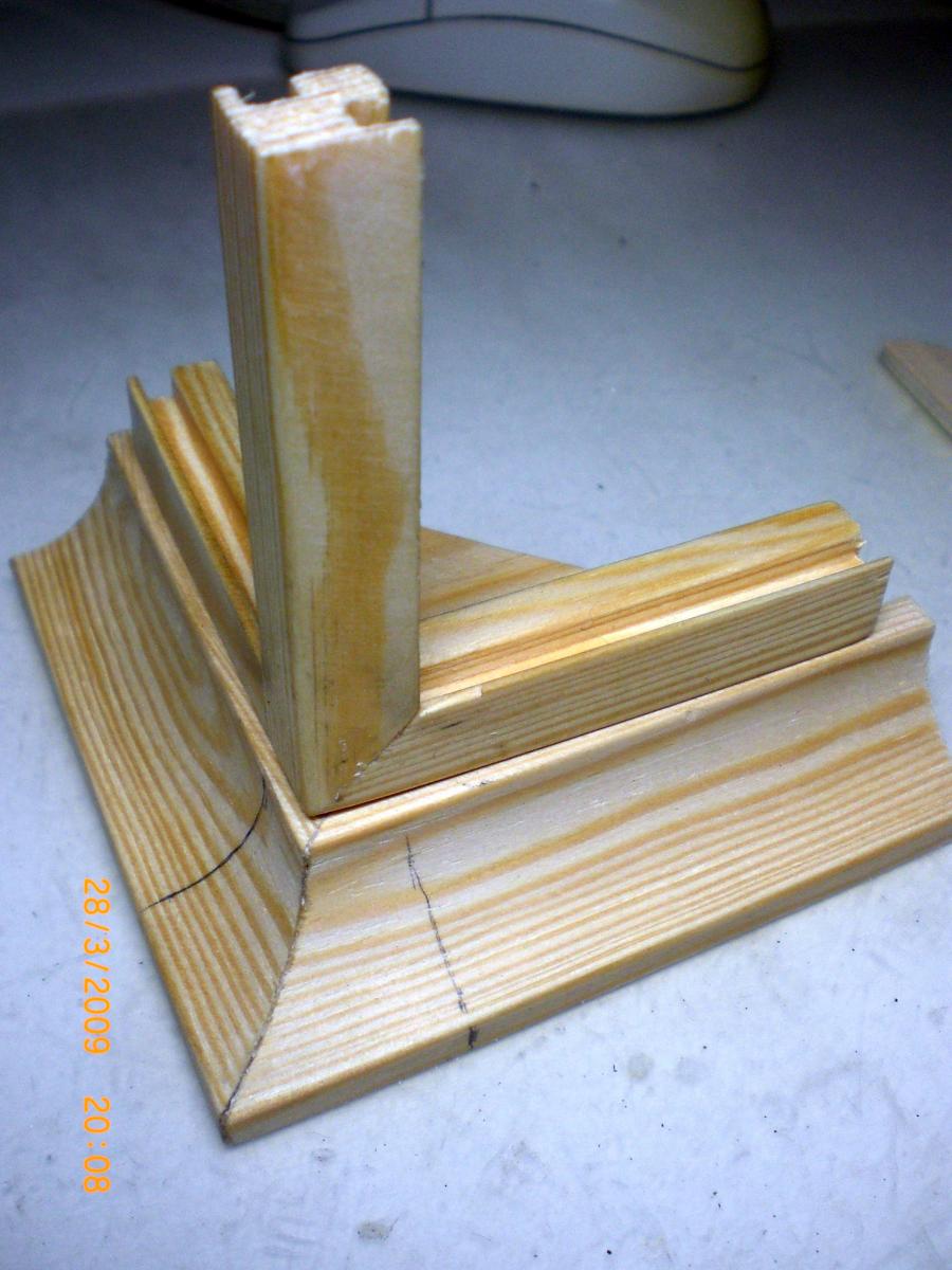
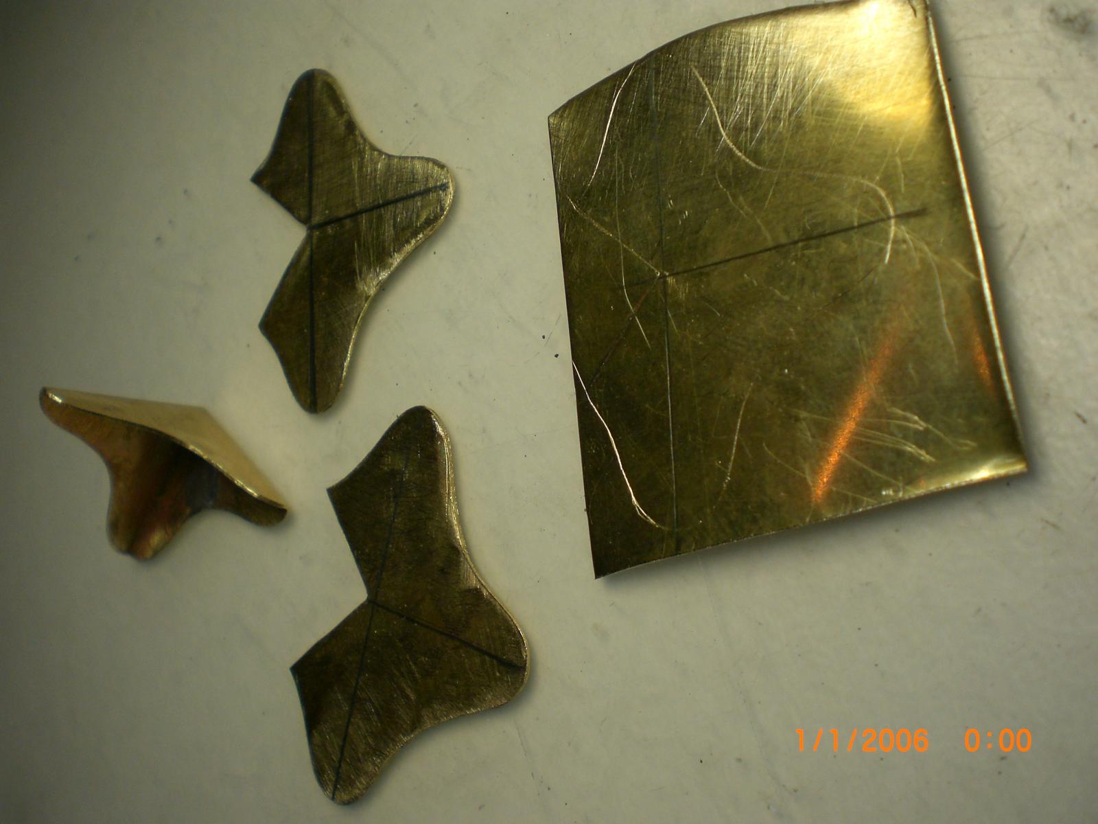
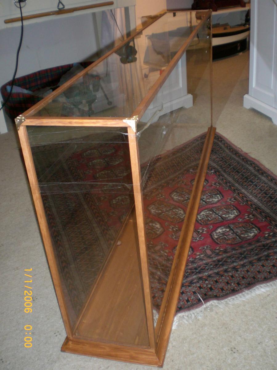
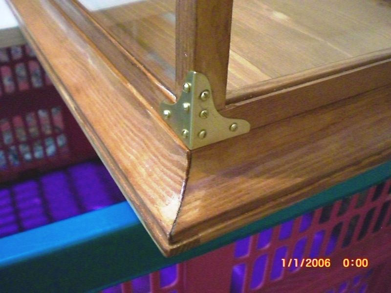
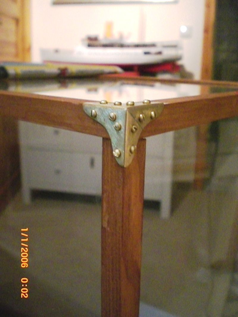
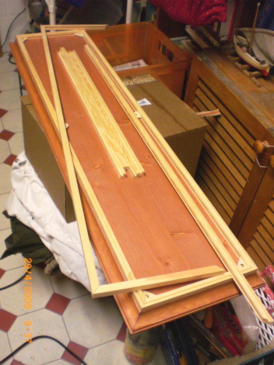
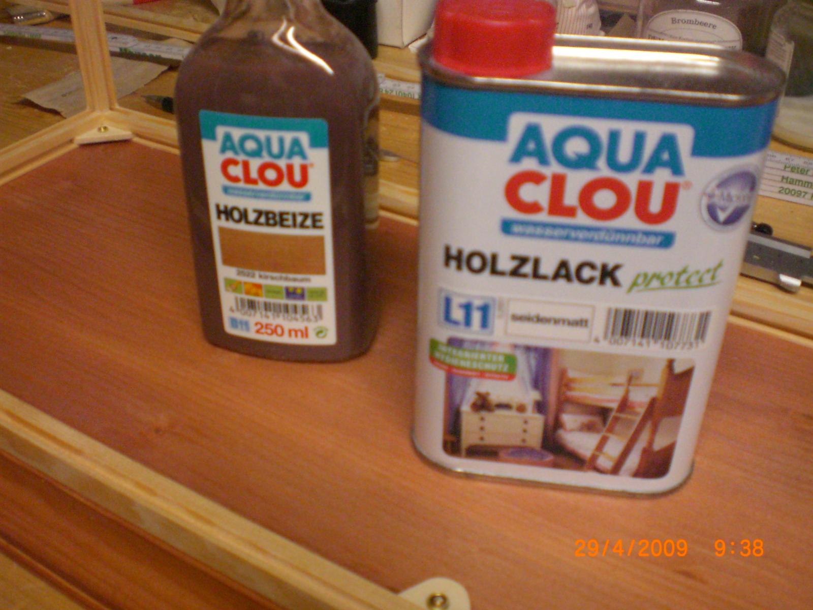
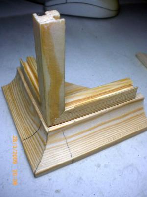
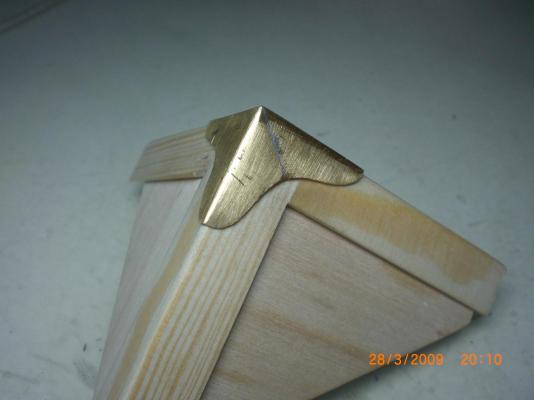
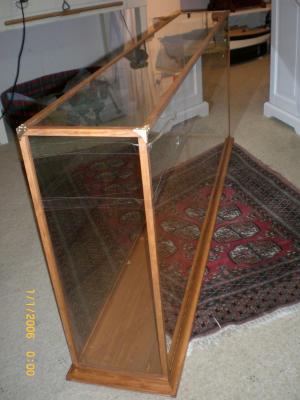
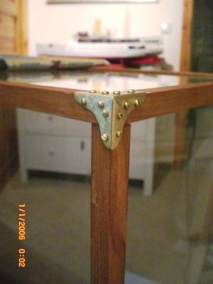
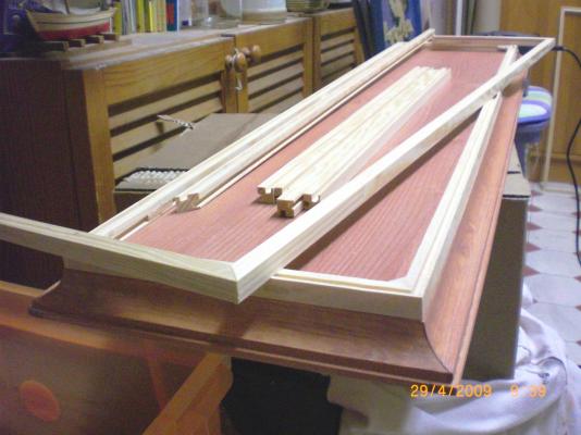
Build log part 21 (this is the last part) This covers the self-built Heinrich Kayser`s glass dust-protection case first doing a sample, trial Corner Arrangement, enabling exact calculation of all to be cut lengths and for the to be ordered glass pannels from the crafters and a sample of the brass Corner pattern cutting out with a hand-jigsaw (metal blade) the glass pane bonnet 142 x 22 x 57 cm with its 4mm thick glass is quite heavy and it takes two persons to handle it very carfully. today I use different brass Corners and screws than These shown here, but to push out the boat.... the inner Corners are provided with slightly oversize sleeves that take up the positioning Pins on the case-baseplate the Frame Wood parts due to the required lengths have to be shafted i Chose cherry-stain for Wood for the case, which provides a nice warm tone, and then sealed with two coats of dull-gloss clear varnish I have to date made 5 cases by this way, all still in good solid condition and easy to clean Nils


- 113 replies
-
- 11
-
-
- heinrich kayser
- steamship
- (and 1 more)
-
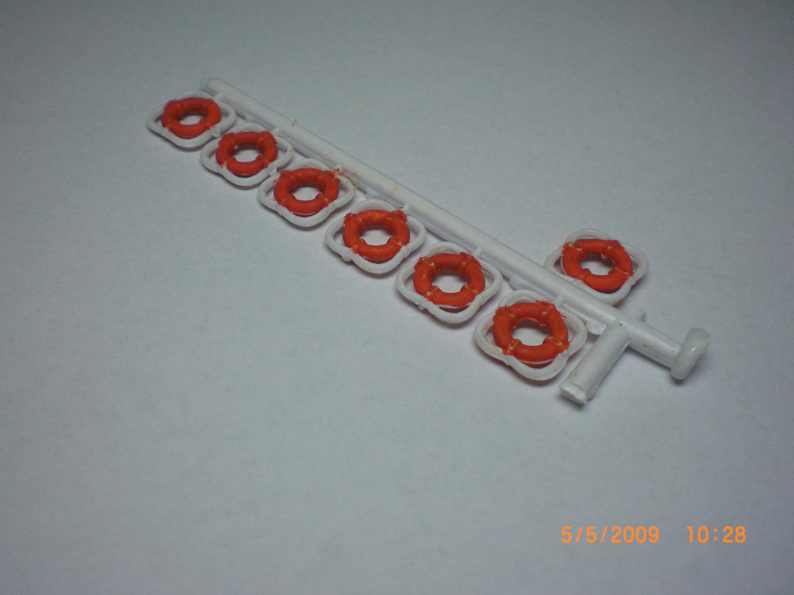
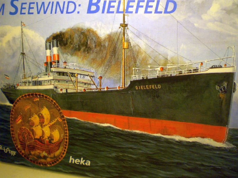
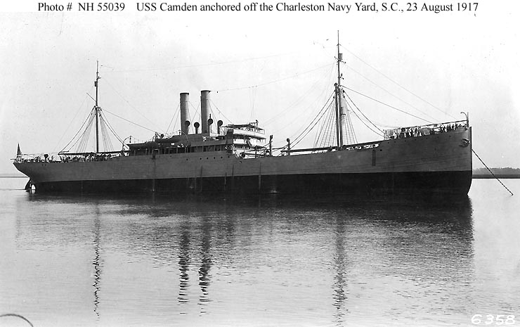
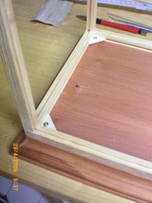
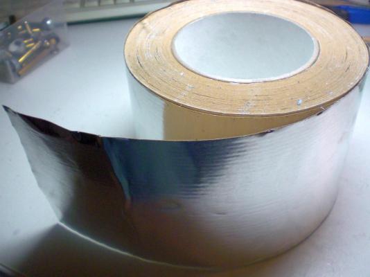
build log part 20 a Little wooden chunk laying over two lower bulkhead portions takes up the press-in M5 nut for safely anchoring the stand bolts through the keel from beneath when I bought this coil of self adhesive alunminium foil I found it quite exspensive at 55,- Euros, but I am so pleased with the Quality an its well protected and effective glue film. If I remember right there once must have been appr 50 meters on the 10 cm broad roll, this enabling 4 models to be plated with and still there is enough for at least one further one to be plated. Here the baseboard with bulkhead positioning rails glued on (made from gathered old rocket sticks, newyear trash) The lifesaver rings I found at Billing Boats (nominal 12x12mm)would be in HO scale this Little 3,6 Inch Long Gem I found at Ebay once it is the rare Mercator # 069 made, scale 1:1250 tin cast "Bielefeld", a sistership of the Heinrich Kayser. Only difference to the Heinrich Kayser : Arrangement, lifeboats behind the work boats Here an illustrated Book cover showing a very nice watercolour painting of the Bielefeld in typical Deutsch-Australische-Dampfschiffahrtsgesellschaft funnel colours, steaming through the Northsea, this painting was performed by marine Artist Henry Albrecht. The original painting is probably in private hands here a very nice Picture of the USS Camden ex "Kiel" also a sistership that served for the US Navy, it is still bearing the old ratlines in the shrouds, as well as a second crows nest in the upper foremast Build log (last part)part 21 to follow....


- 113 replies
-
- 2
-
-
- heinrich kayser
- steamship
- (and 1 more)
-
Thank you so much for your Kind and appreciative words, Bindy, Crackers, Richard and Popeye and also many thanks to all other fellow members,for their Kind words, comments, questions, and appreciative pressing the "I like" Buttons. I feel very honored that this build log was so much liked through the building sequences. This provides me pleasure to prepare the next build log project Now to round up the Project I shall post the two last parts today also comprising a short look at the glass case making for dust protection, which is a must for such a model. It may have been recognized that the Pictures of the completed model are to be seen in my Album in "Gallery of scratch built completed models" If there should raise questions, comments,etc. to the build log parts, please feel free to ask me at any time, I shall be happy to answer Again, thanks for being tuned in - Auf Wiedersehen- Nils
-
Well done Jack ! not an easy scale you have Chosen, but it is turning into a beautiful Glocester fisherschoner Nils
-
I like this Little schoner of yours Bob neat planking, fine lines, Looks like it is going to be a Beauty Nils