MAGIC's Craig
-
Posts
50 -
Joined
-
Last visited
Content Type
Profiles
Forums
Gallery
Events
Everything posted by MAGIC's Craig
-
Interesting indeed. I wonder about that schooner on the ledge, though. The bow of the Elizabeth Howard shows the long "spoon" bow of the time and yet, it appears from the photo that the stem in outline is considerably closer to a plumb bow. Did she get damaged in the bow and was later rebuilt? Or did the article mis-title the schooner on the ledge? Just curious. Craig
-
I am delighted to see your update, Steve. Yours is one of the builds that has that special attraction for me. Very nicely detailed. Before we headed out to WESTPAC, we were issued a grey painted Boston Whaler with outboard to stow up on the boat deck. Handy for light duties but when it became necessary to send a crew back to secure a towline to a loose, ammo-loaded barge - as Typhoon Rose bore down on us - the bosun mates were glad to have one of the motor whaleboats to take them out and back as the seas were beginning to get ugly. Craig
-
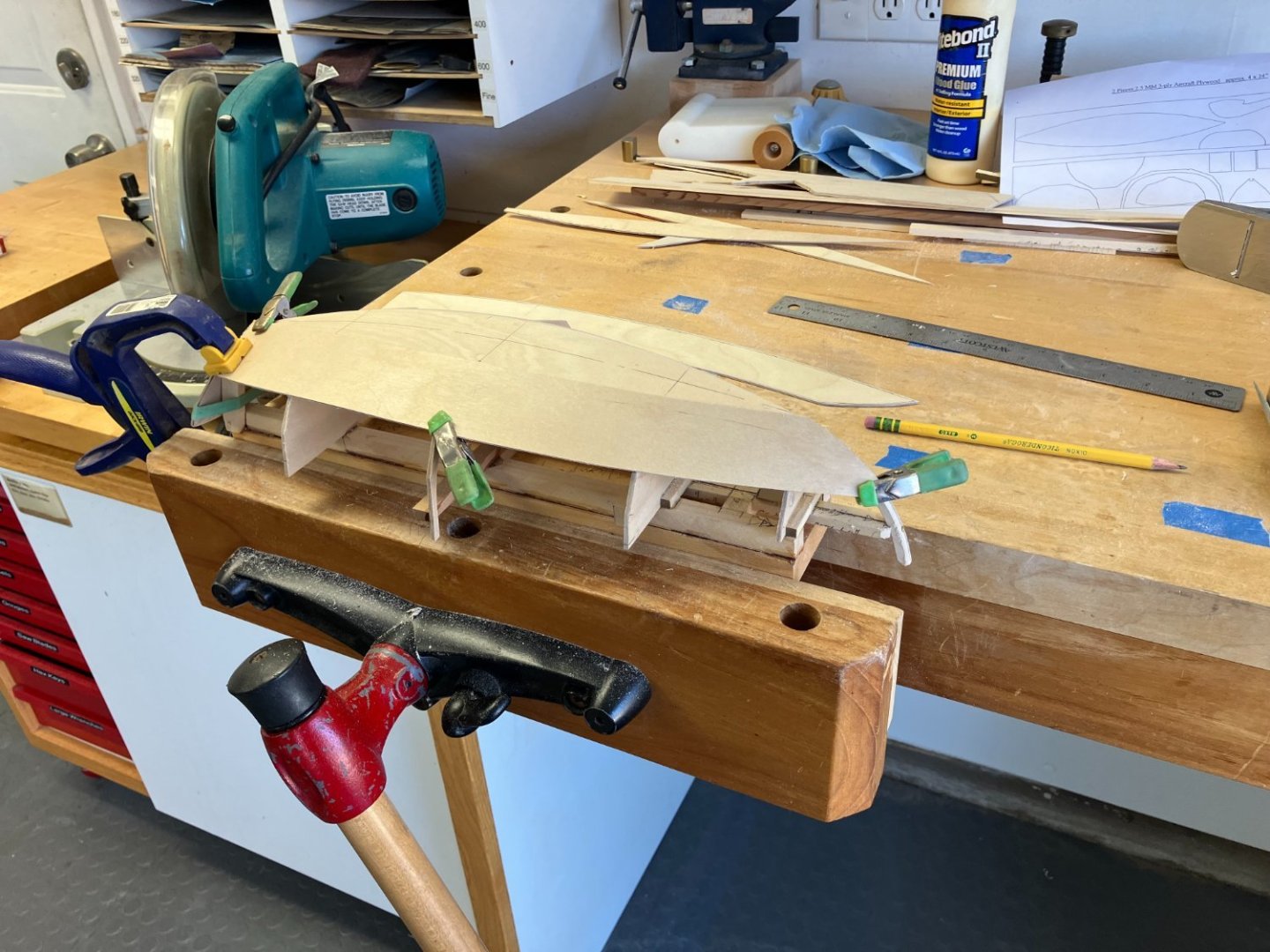
This is one of my favorite stages in visualizing a new hull. Looking good!
-
Tim: Nice creative thinking to make it all come together so nicely! I will happily join the crowd following along on your build.
-
Fascinating work, Nils, and quite entertaining to follow along your construction sequence. I also will look forward to seeing how she comes together. 👏 Craig
-
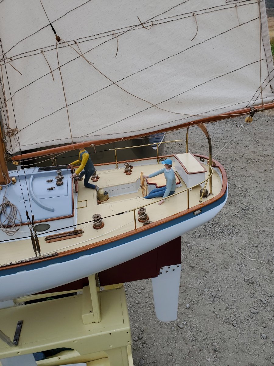
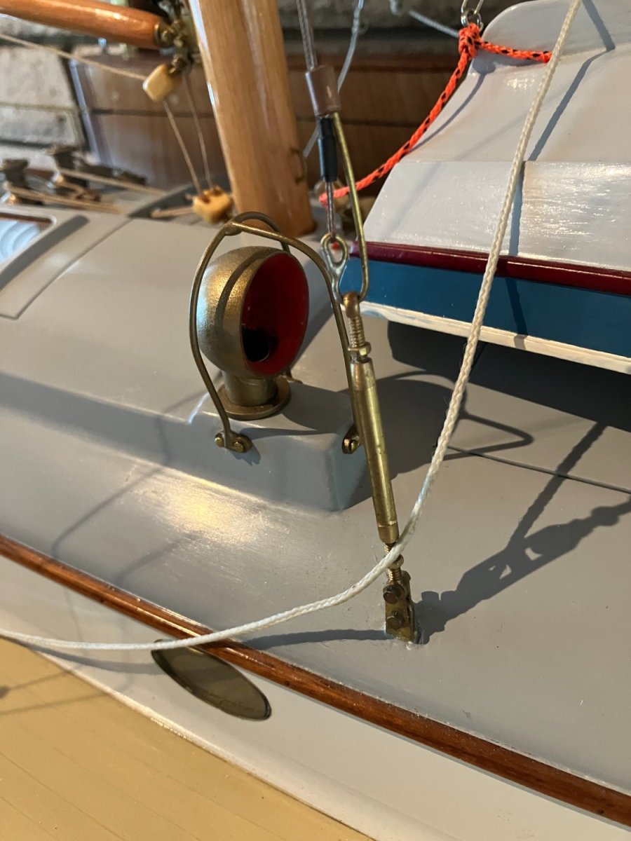
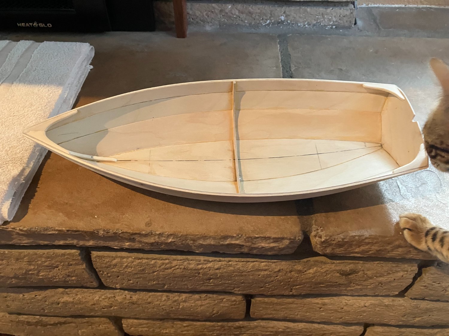
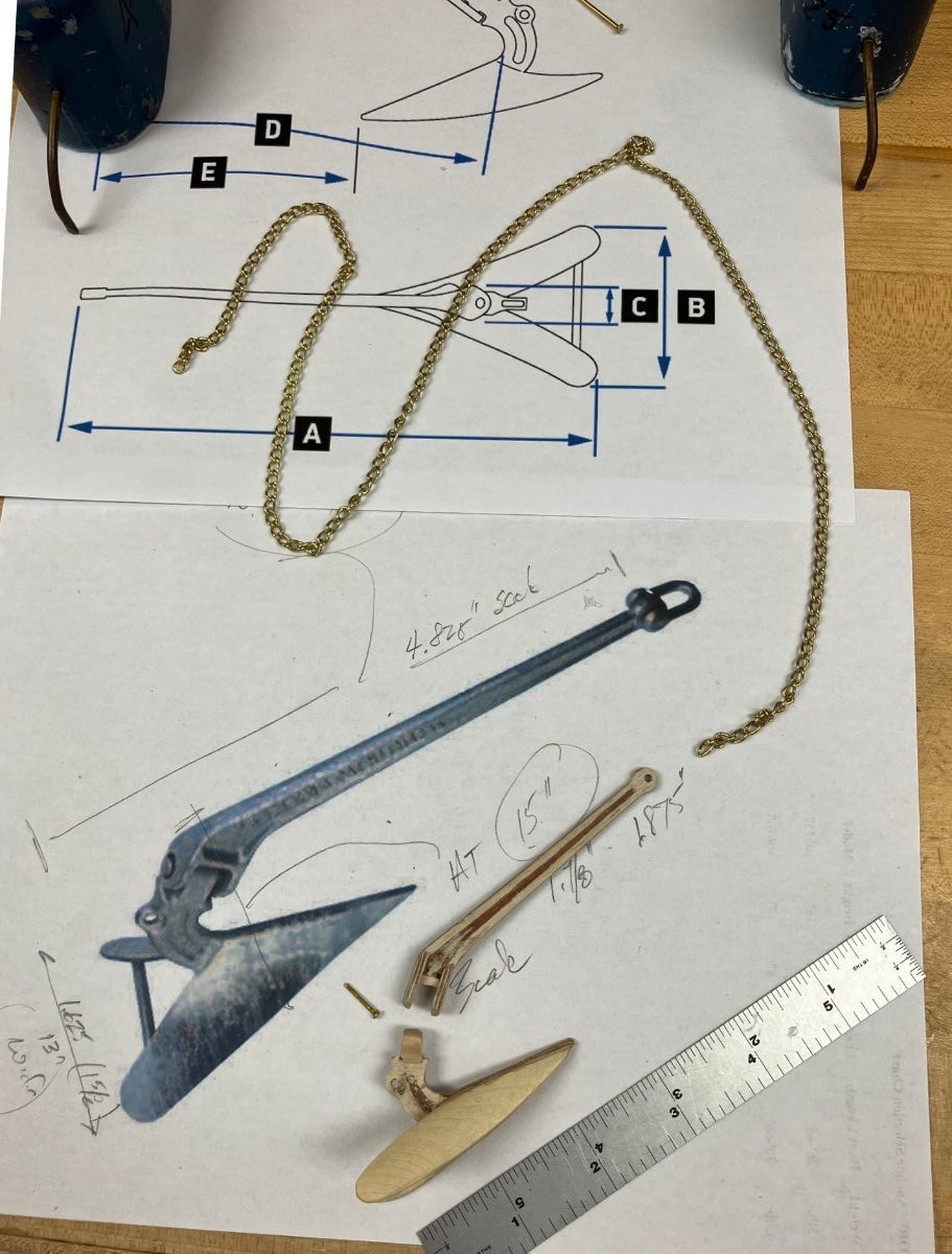
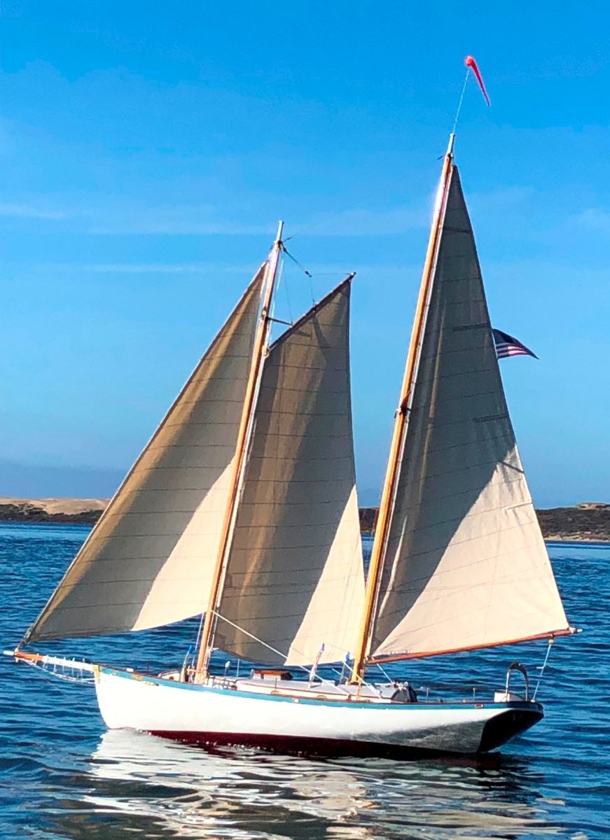
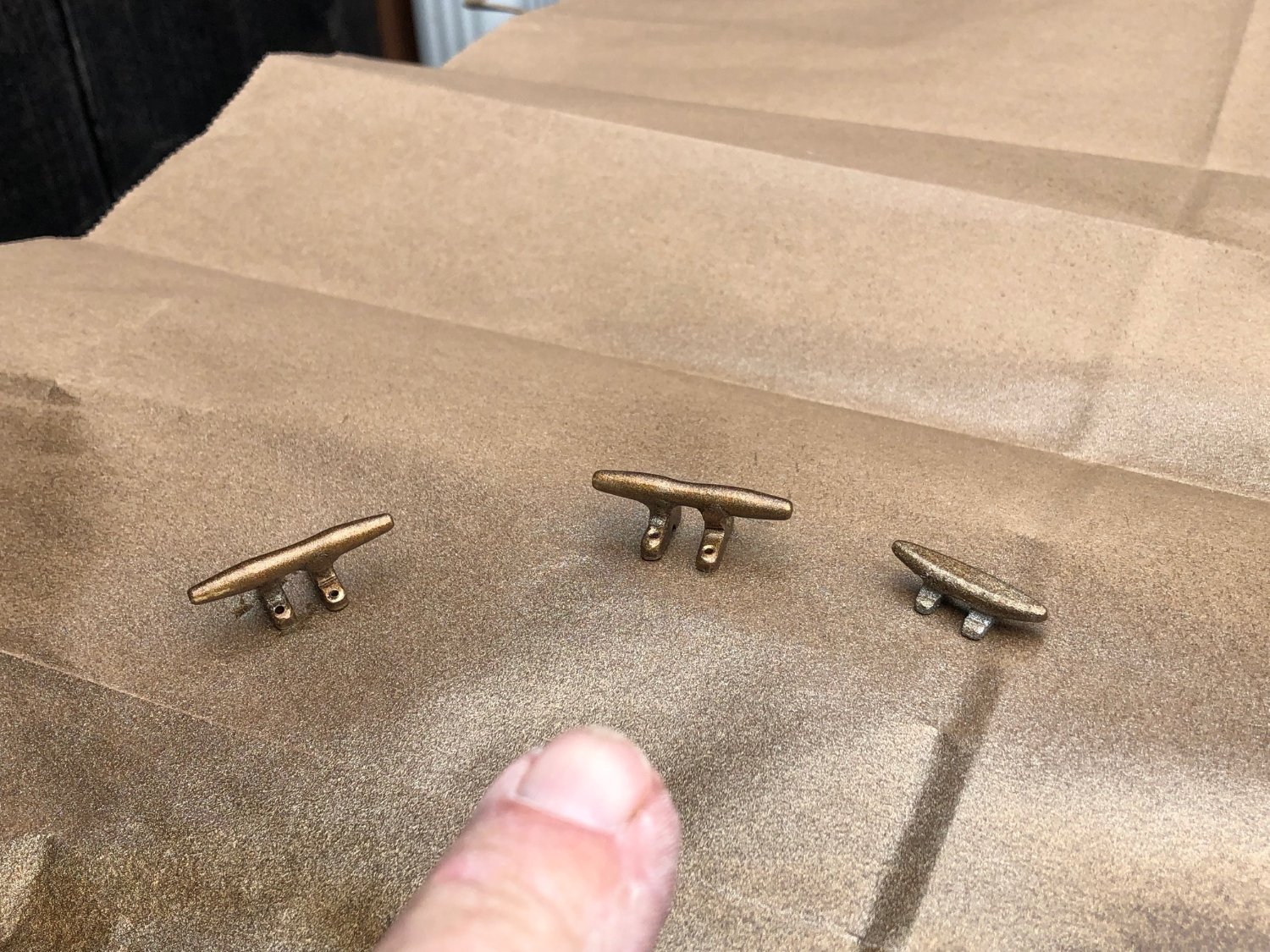
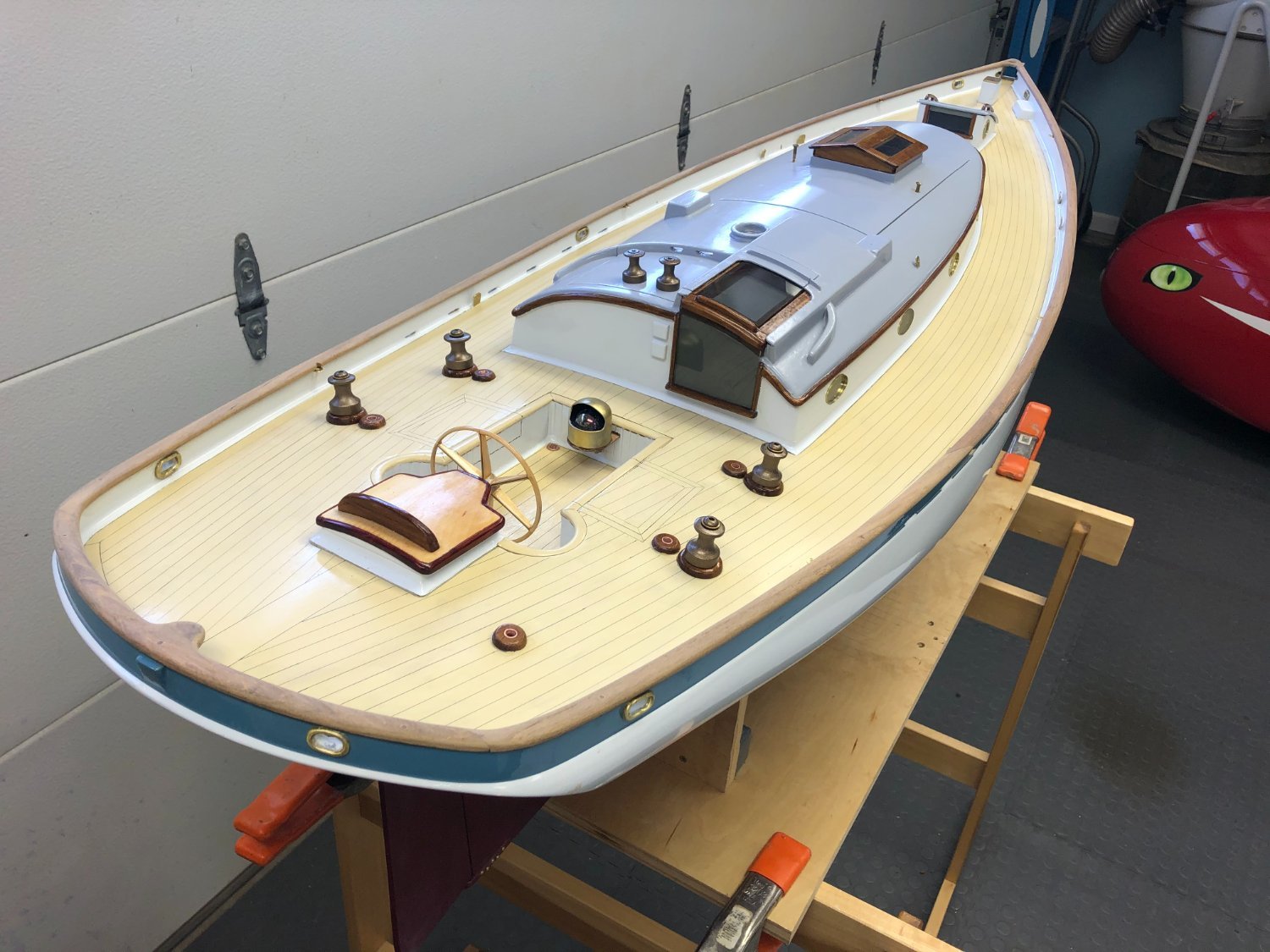
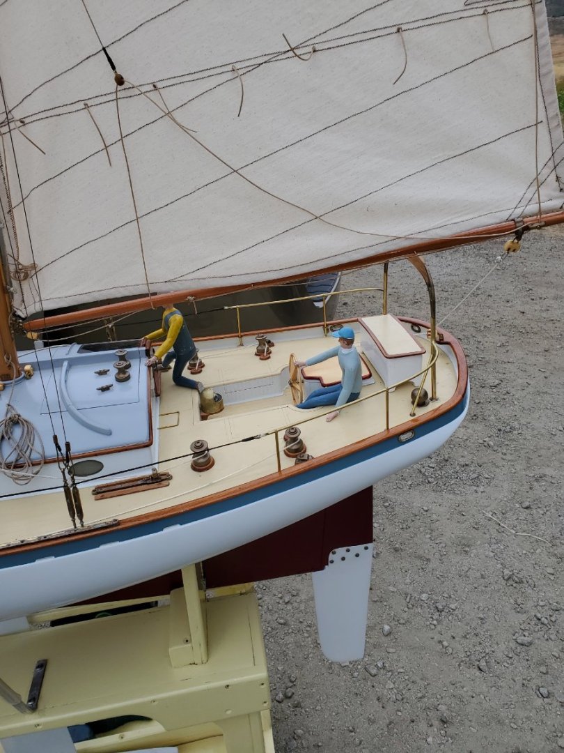
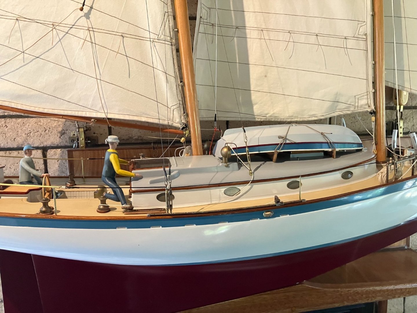
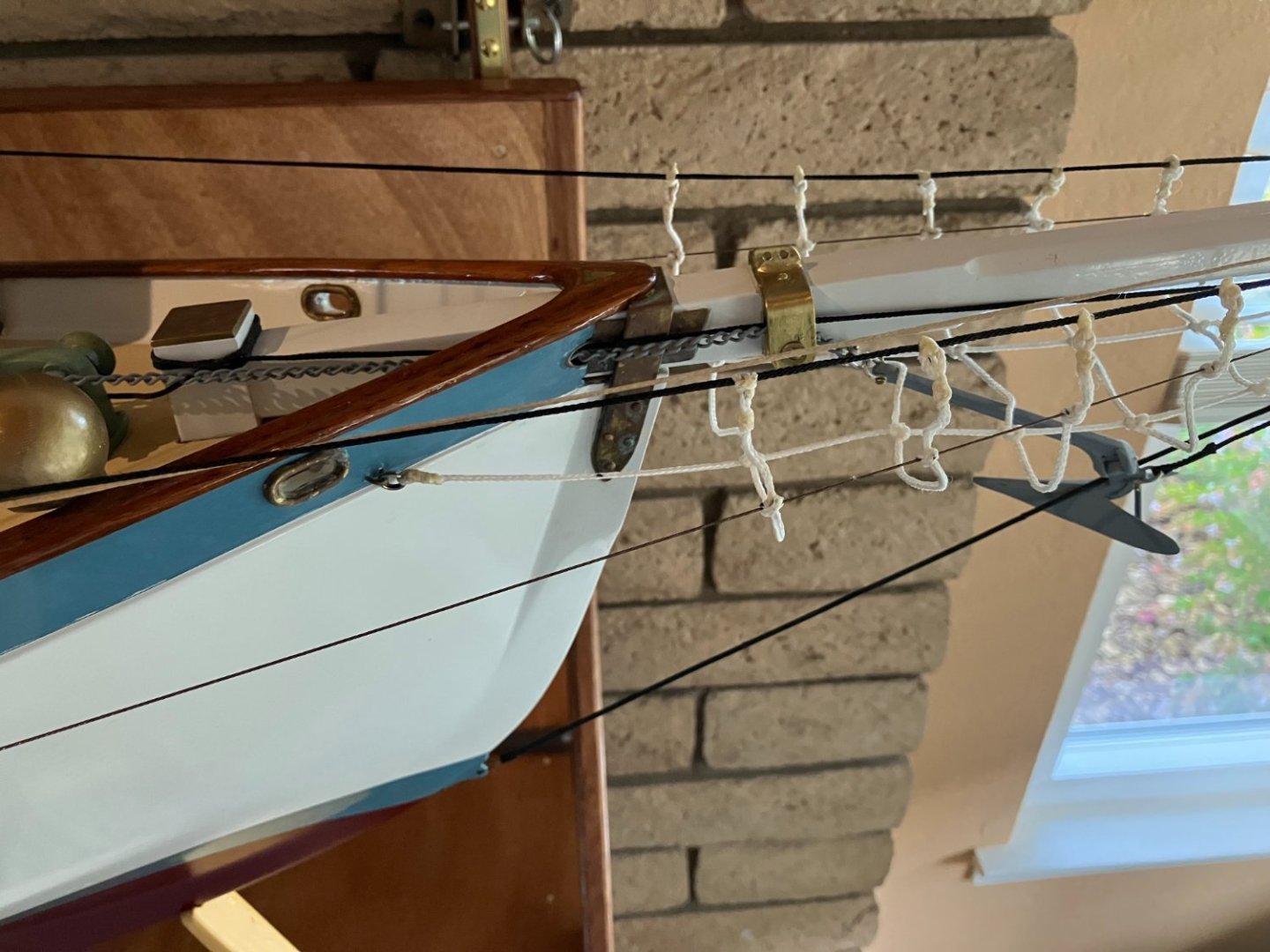
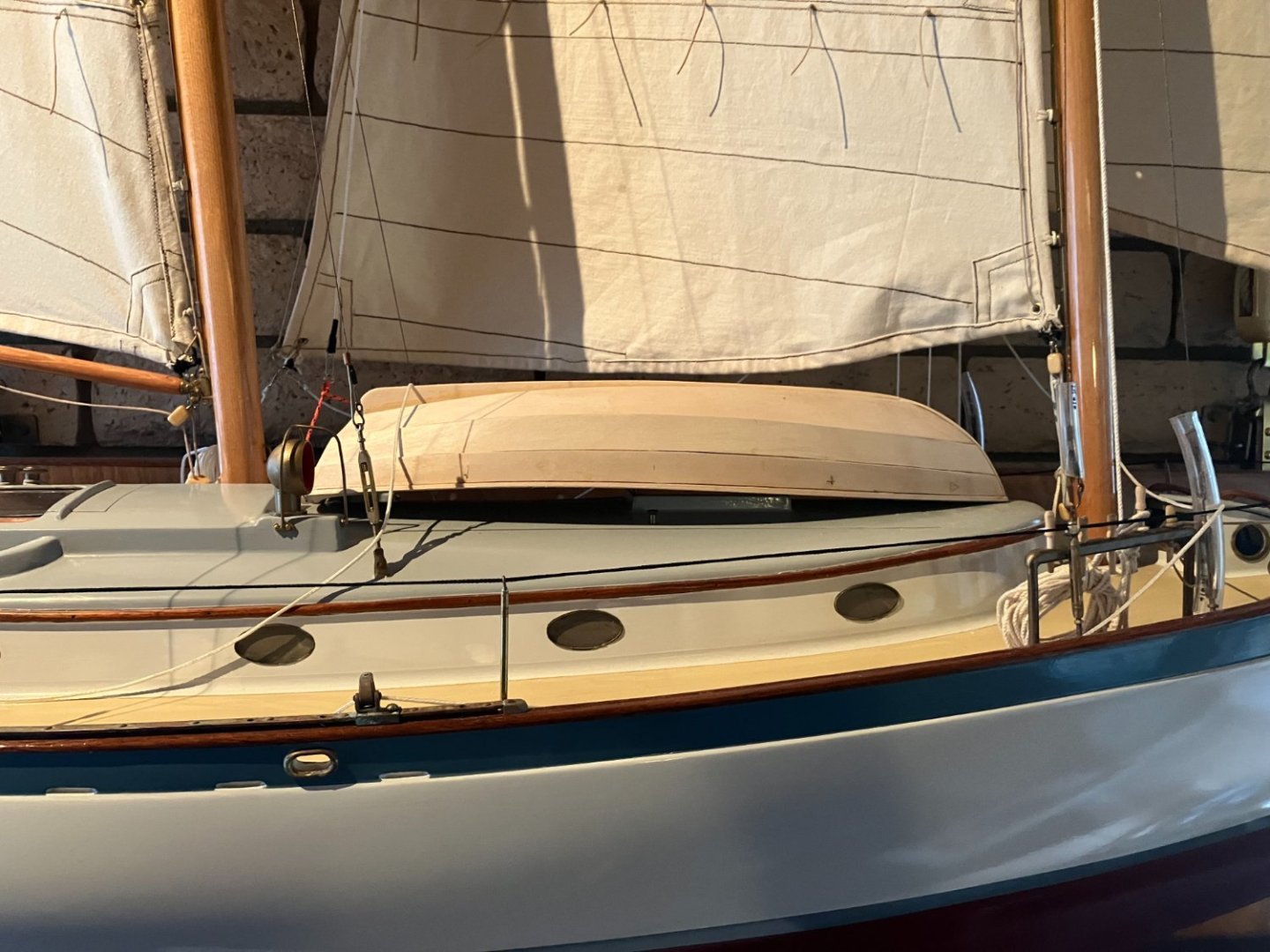
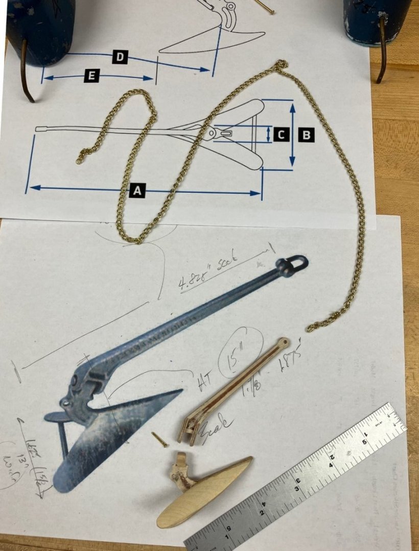
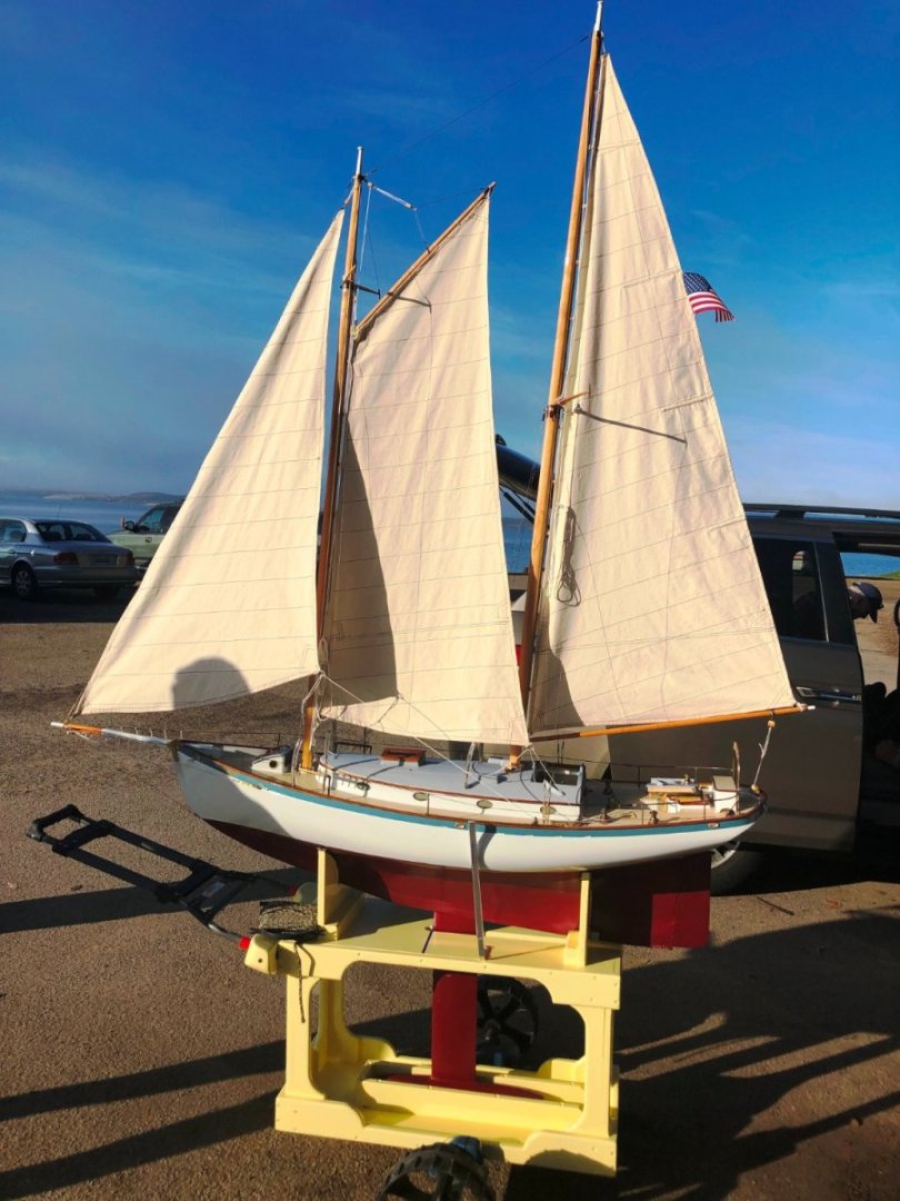
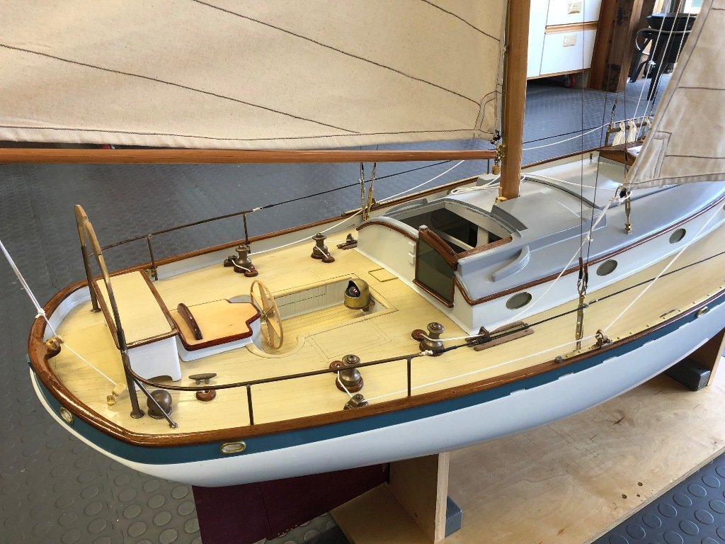
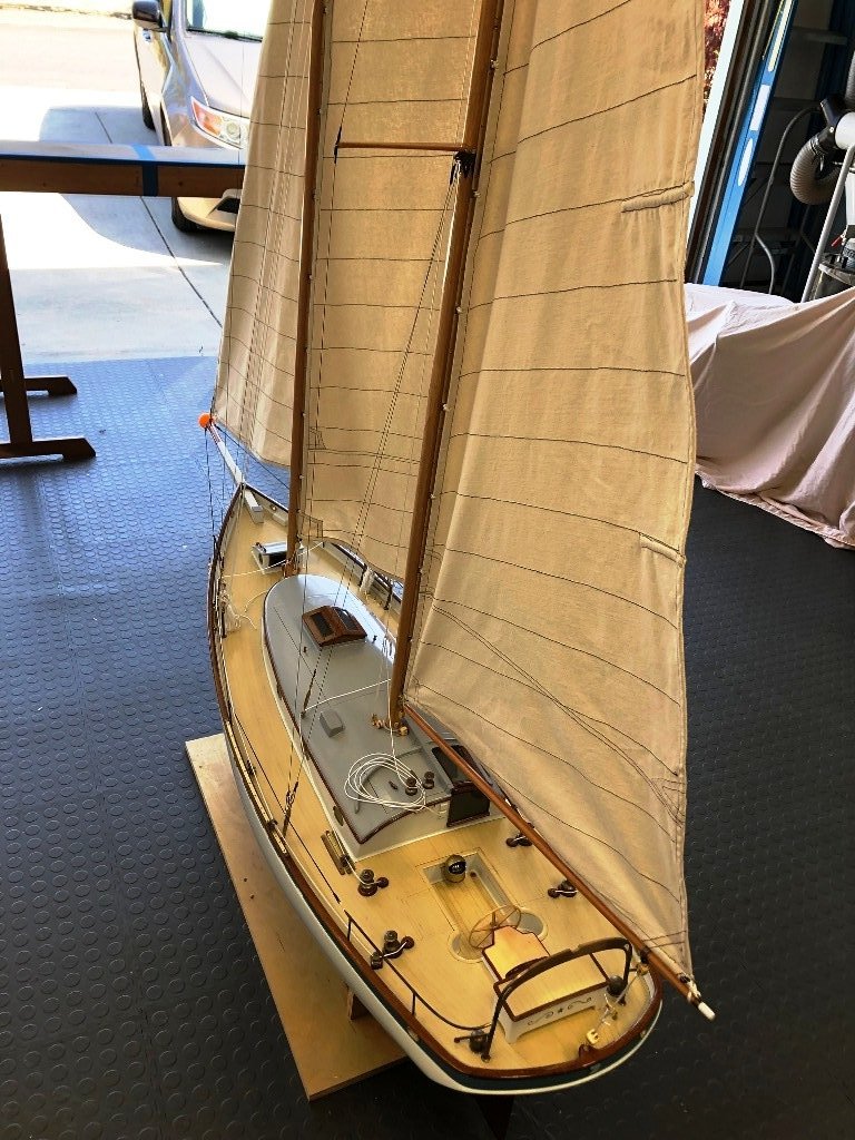
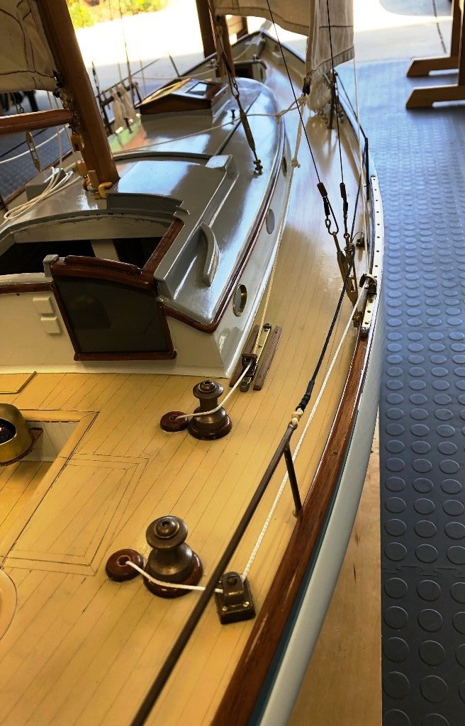
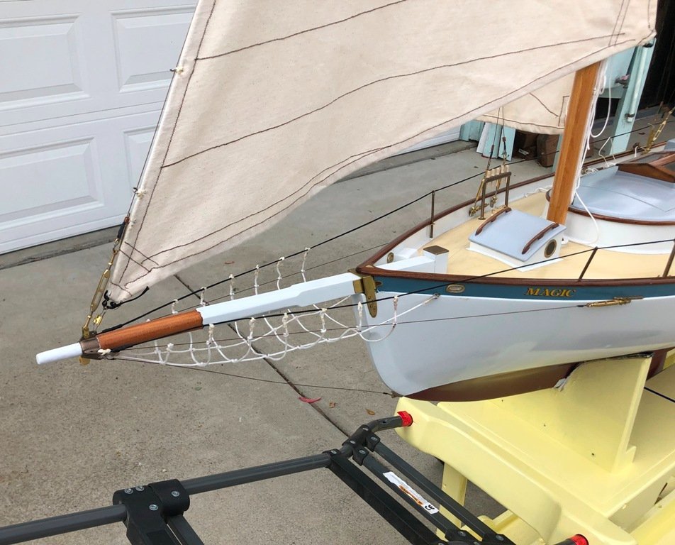
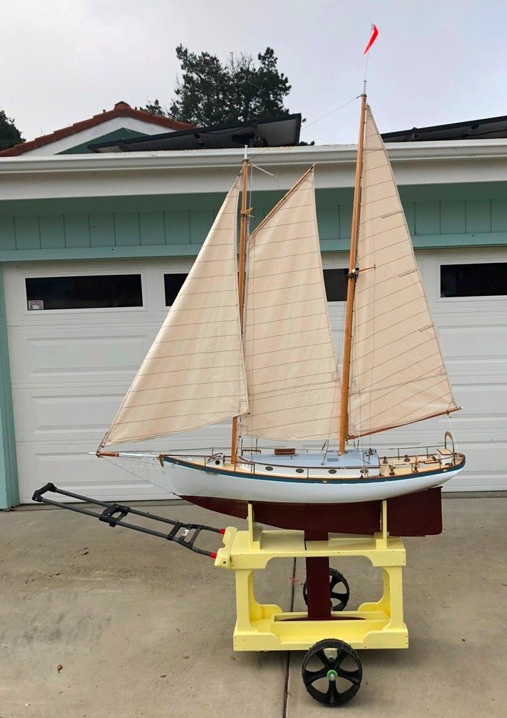
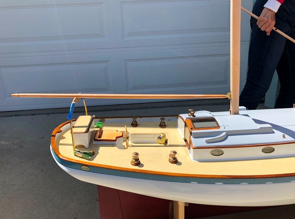
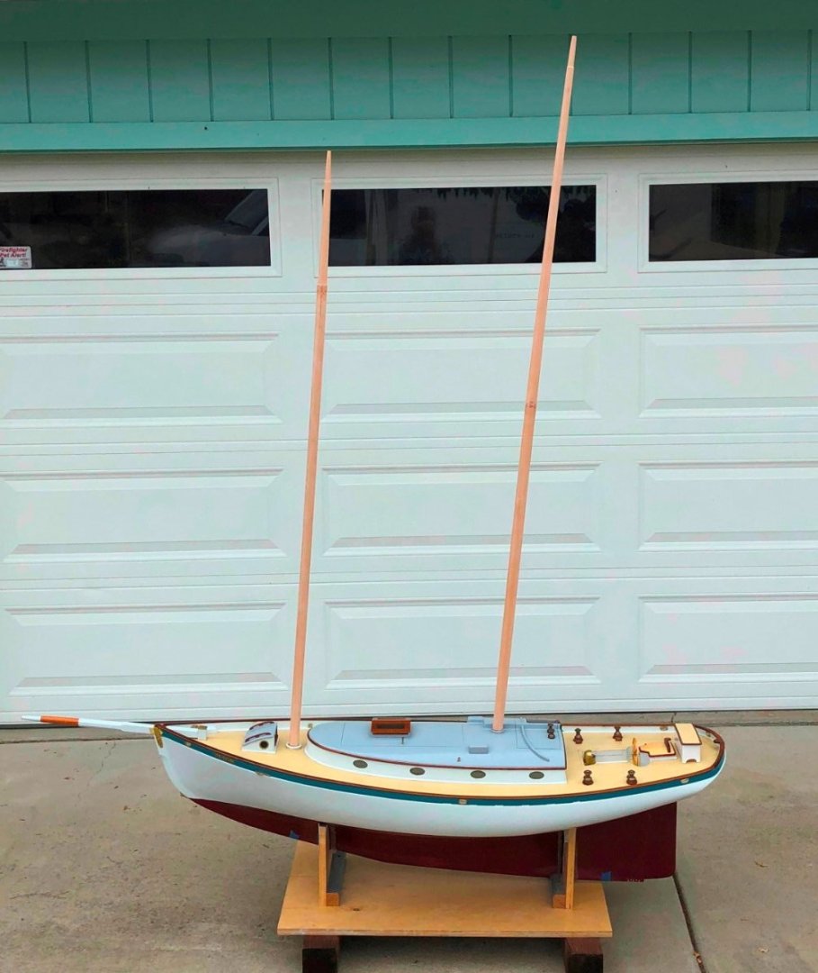
To deal with the somewhat ineffective rudder issue, we added crew aboard and to assist them, I created an additional rudder blade which bolts to the lower portion of MAGIC's scale rudder when needed for actual sailing times. In the so-far not-very-effective effort to cut down the drag against the lazy sheets, both the mainmast's fore lower and foremast's intermediate shrouds were released from their respective turnbuckles and secured to bails on the forward faces of the masts. The correction of this tacking problem however still remains to be sorted out. MAGIC, for accurate display purposes, needed additional deck hardware and rigging detailing. Dorade cowls were made up from drilled out 1" diameter wooden balls and 1/2" brass tubing, then painted. The two after cowls also required sheet guards, which were fashioned from brass rod and small drilled plates. A 2-speed-style windlass was created from carved yellow cedar, plywood and turned wooden gypsies. The chain for the anchor was fed through a brass-lined opening in the bulwark, then over a newly-fashioned chain roller at the staysail tack band down to a (painted wood) CQR hung below the bowsprit. Rigging enhancements included reef points and tackles, a topping lift for the main boom and a jib downhaul. The crew needed a Shellback dinghy for shore liberty (and to transport the cat). This was built up from a 1-1/2" to 1' (1:8 scale) "kit" sold by the WoodenBoat Store, which consisted of a set of scaled down drawings, 2 sheets of carbon paper, a set of printed recommendations for a building sequence and various-sized pieces of pine and plywood. We painted it to match the original aboard MAGIC and lashed it down. And this brings the construction blog up to date - July 2023. There will probably be a post or two more when I get her sailing smoothly. This post has perhaps exceeded the limit for photos, so I will start another reply with a final picture or two of MAGIC sailing on a local lake. Craig


-
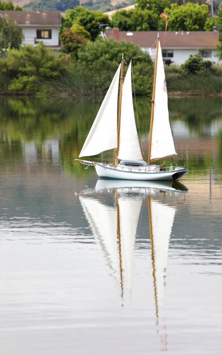
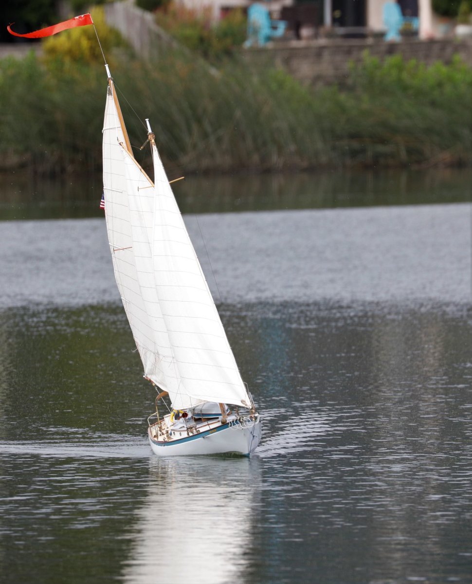
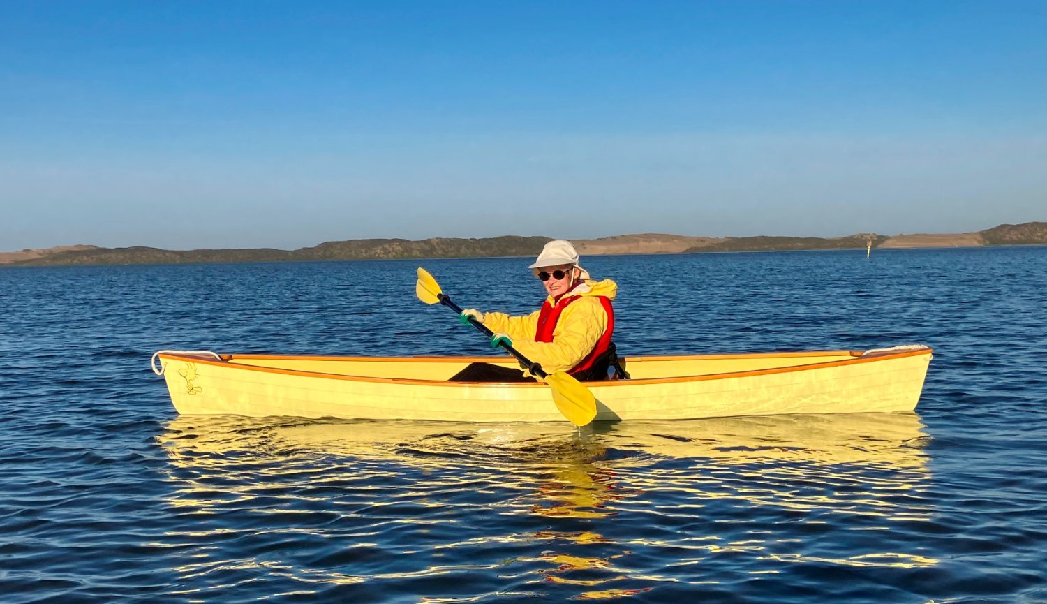
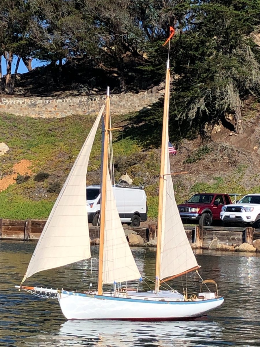
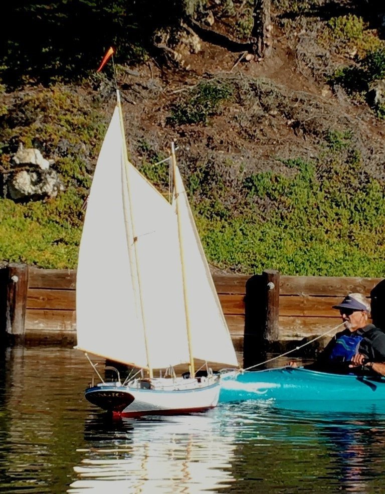
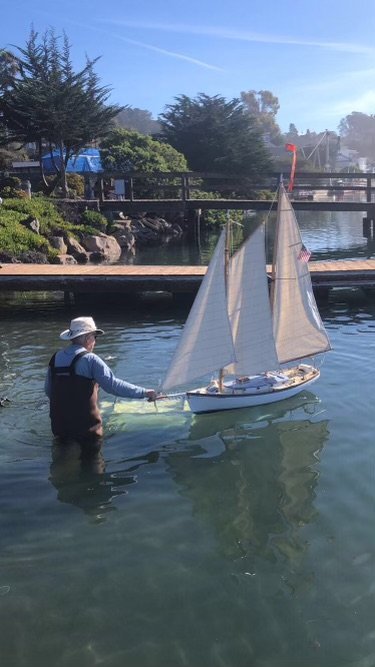
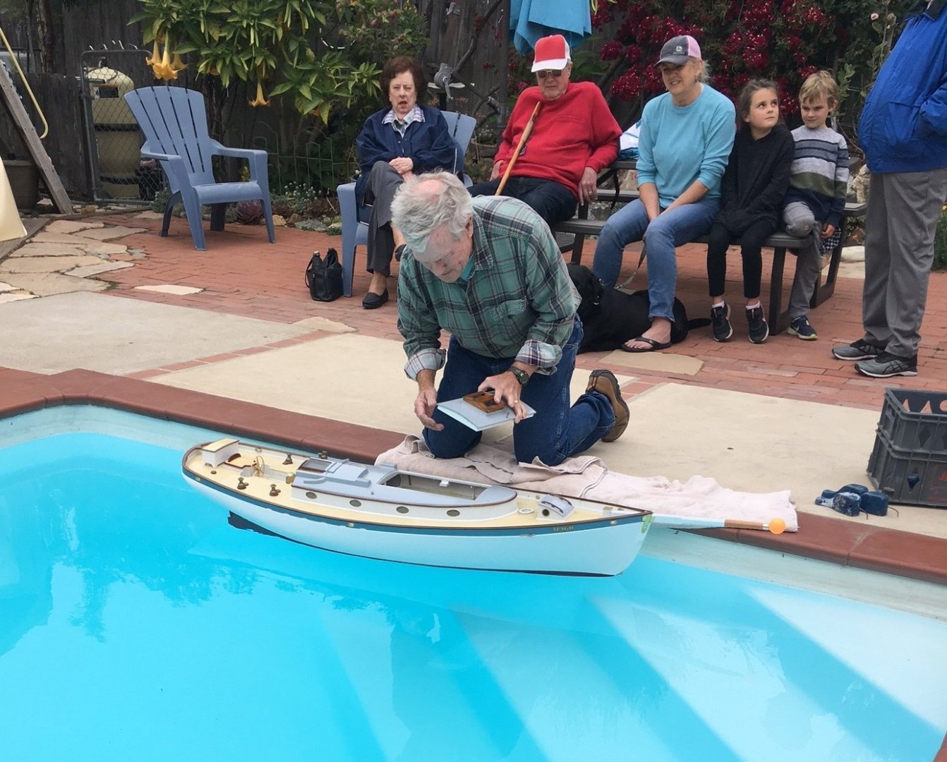
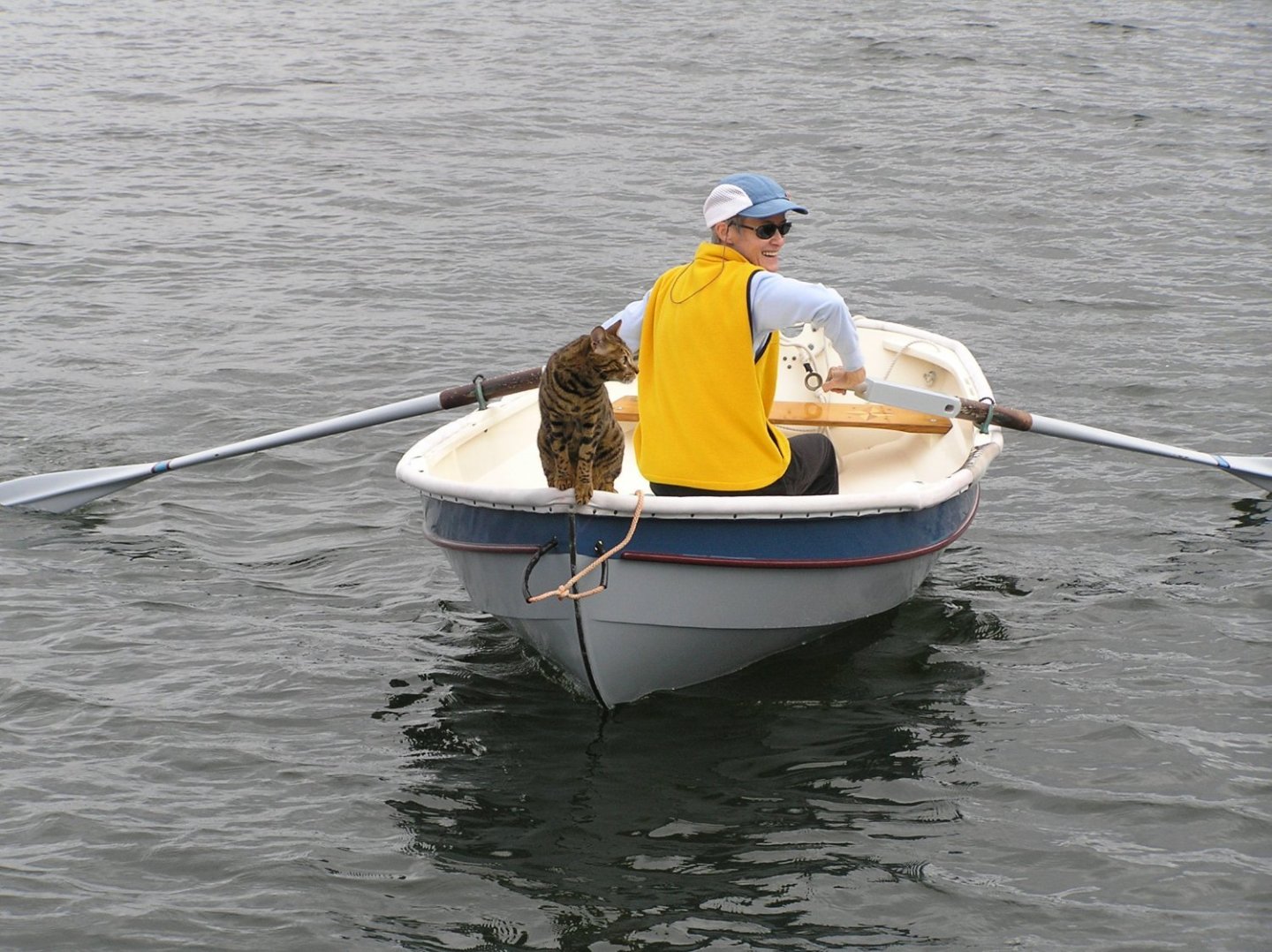
Bob (and others so interested) For a model, she seems to slip along nicely. She is reasonably quick in response to the transmitter's signals. The first sea trials indicated that additional rudder area would permit less rudder to need to be applied. Tacking was not crisp because both the headsail and the foresail lazy sheets were hanging up against the standing rigging. And, you know, after years of sailing the original MAGIC from the cockpit, changing headings was intuitive. Rudder control while standing ashore as the model sailed away was also not a mental stretch...but keeping it all together when she's heading back will take more training of the operator. The jury is still out on the functionality of the sheet servos because of the lazy sheet issue. The servos seem to have the necessary torque but they do take time to tighten the sheets on the working side, however I'm not trying to make foiling-speed tacks. Not sure whether the sheets would release as fast as simple rudder action would let her up. More trials required there. When she gets becalmed or "otherwise incapacitated" ( that expression got us chuckling, Bob), Vicky or someone else serving as "Rescue", paddles out to get her. Here is Skip Allan serving as a reverse tugboat when the wind died the first morning. (Photo by Vicky Johnsen) And Herself in WOODSTOCK. a Tom Hill ultralight glued lap canoe

-
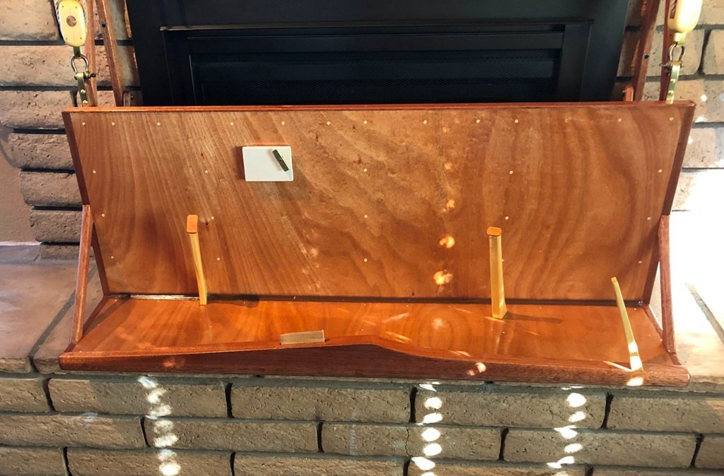
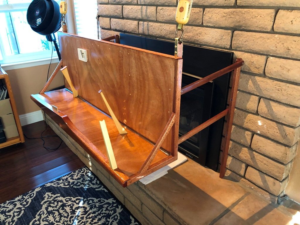
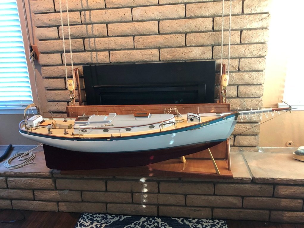
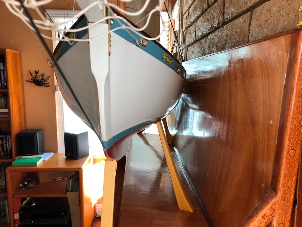
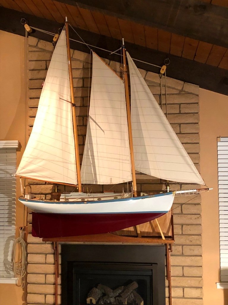
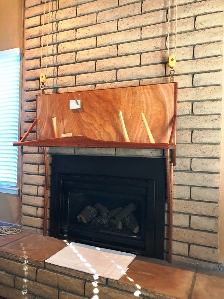
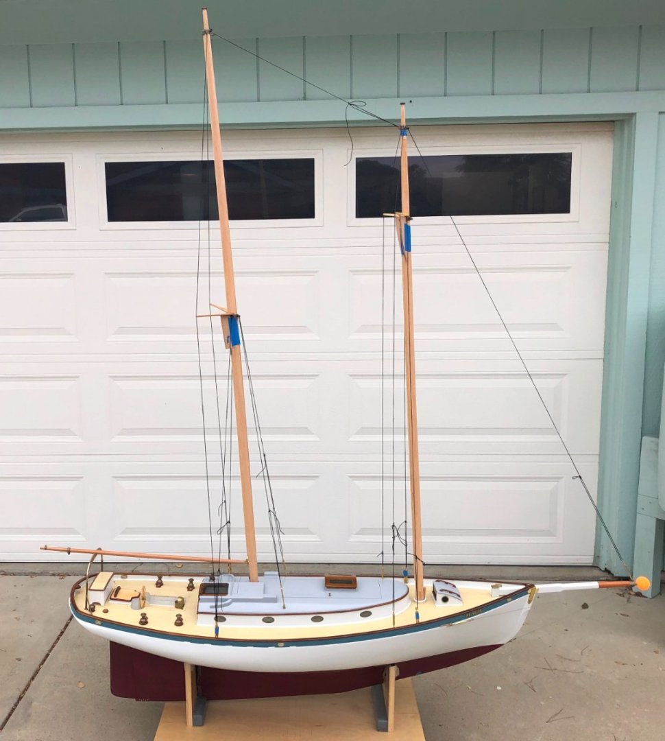
It doesn't seem fair to leave this tale at the above picture. We first launched MAGIC in late November, 2021 and managed some preliminary sea trials. These generated a bit of a "squawk" list, as might be expected and I managed to work on a couple of items before her next sail 2 months later. Photos by Vicky Johnsen Above image taken by Vicky Johnsen in early January, 2022 We were fortunate to be able to build a mounting/display cradle in the house to hold her before life intervened for 15 months. The only space with suitable height was above the fireplace (we have a cat - 'nuff said) but the supporting shelf needed to be able to be raised and lowered. Hollow-cored panels were glued up and bonded together and the hull rested along her centerline with a maple stub projecting up into the keel slot. A bolt projects from the backboard through the midship hawse of the bulwarks into a retention plate on the inboard side. This arrangement keeps the model from tipping over away from the wall. The mainmast clears the roof T&G by 3/8". And here she sat, not quite finished nor properly sailing for the next 15 months or so. Nearly current...


- 67 replies
-
- 10
-

-

-
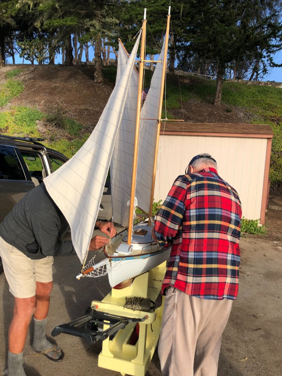
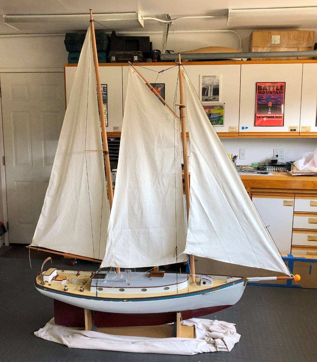
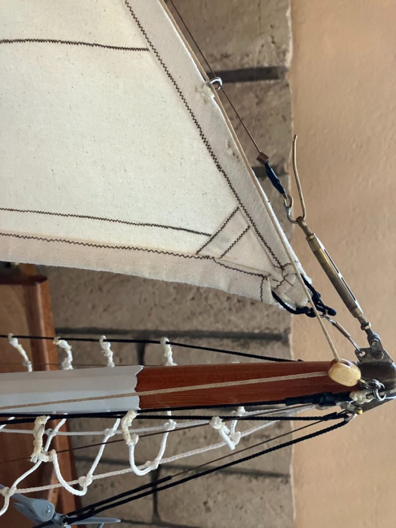
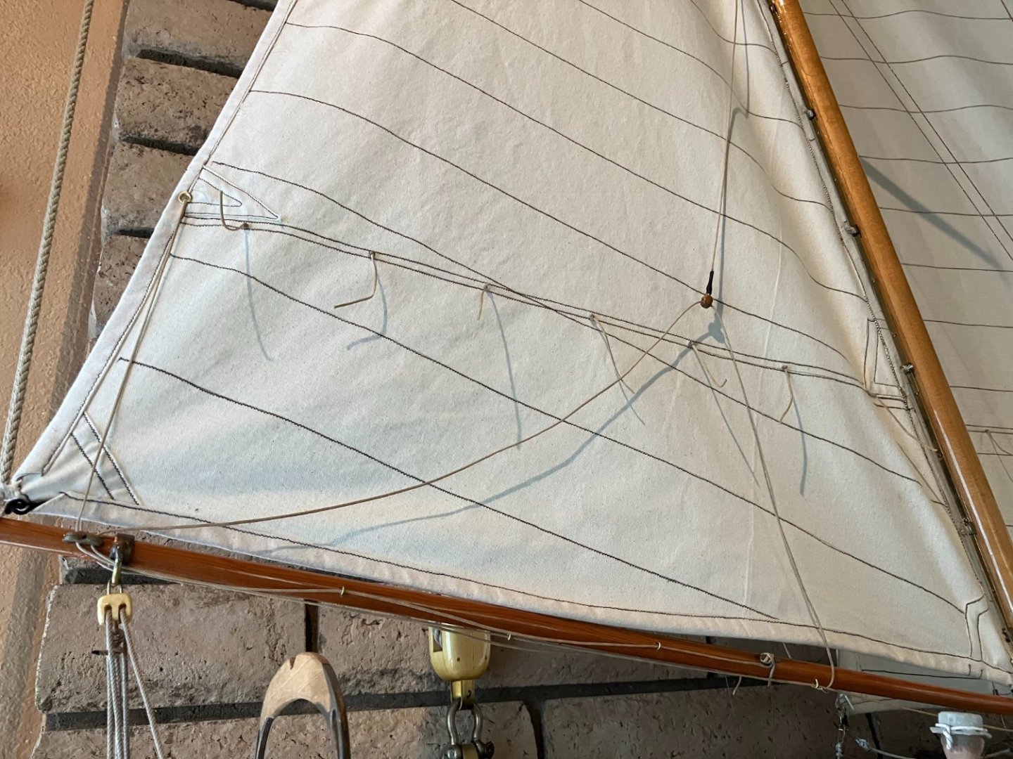
Sally soon stopped by with the newly-sewn up sails and I set to doing the necessary handwork at the corners, the sail slides and the fitting of the mainsail's battens. Once this work was done, I raised the new sails for the first time and began setting up the running rigging as well as tweaking the positioning and luff tensions on the masts. The bowsprit net was knotted up and hung in place. And I started getting impatient to start MAGIC on her sea trails even though there remained a list of projects yet to finish. In our locale, there are very few useful launch ramps, either into a bay or nearby fresh water lakes. At that time, (November, 2021), we were also further limited due to the extreme drought's effect on the levels of the lakes. Since the useful access to the bay's two ramps was strongly effected by tidal height/current, there were also only a couple of days a month when, winds permitting, an initial launch for a sea trial made sense. First launch and sea trials next

-
Bob: We are still catching up from the past, but getting closer. You are correct, of course, the young woman at Joann's would not have had any spinny cloth. However, she kindly helped me sort through the myriad choices available in weight and color to find the light tan (natural) duck that seemed suitable. Thanks for the favorable mention on the sail slides. My soldering skills still need lots of improvement though. Next model will require a fair bit.
-
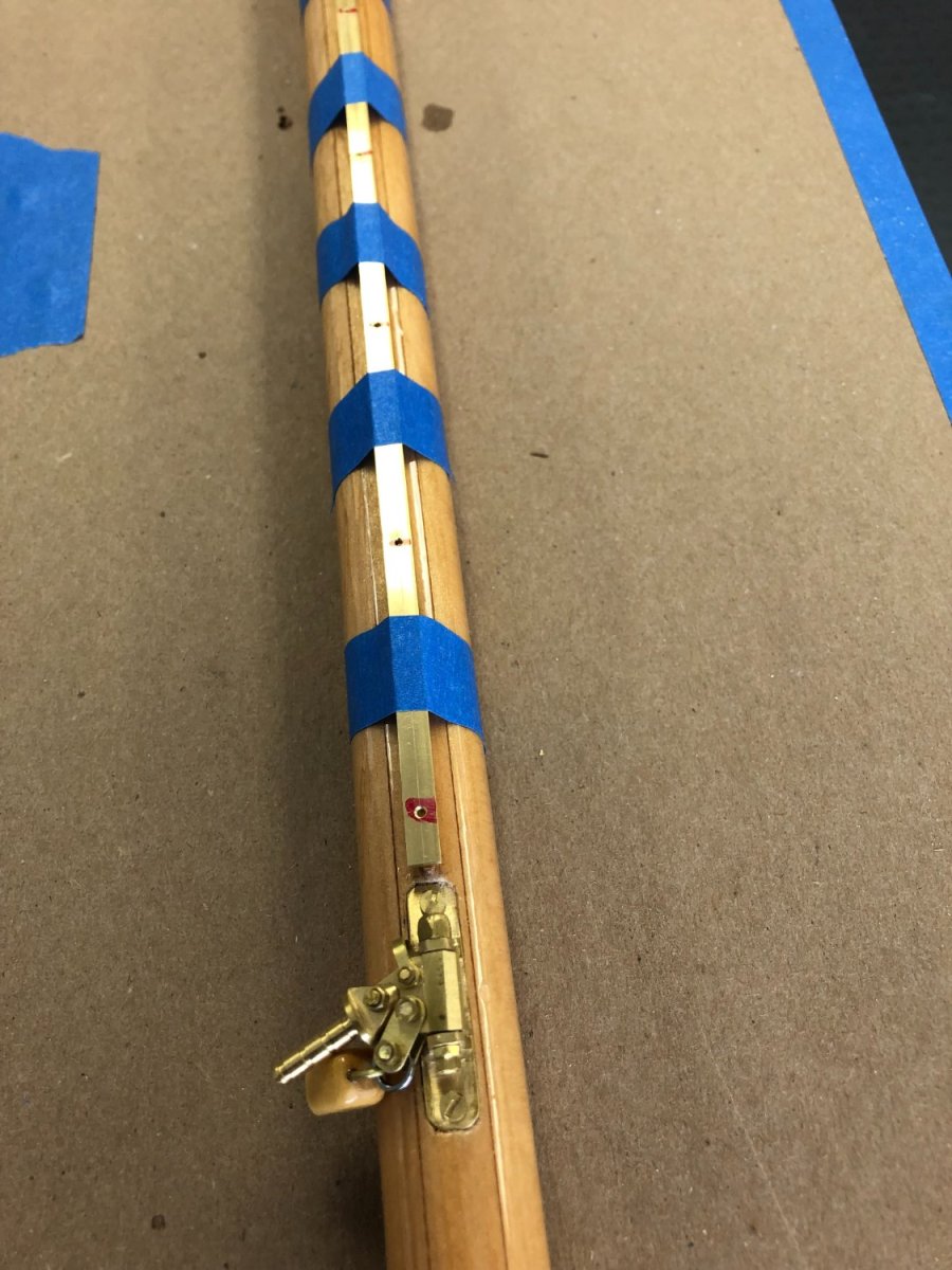
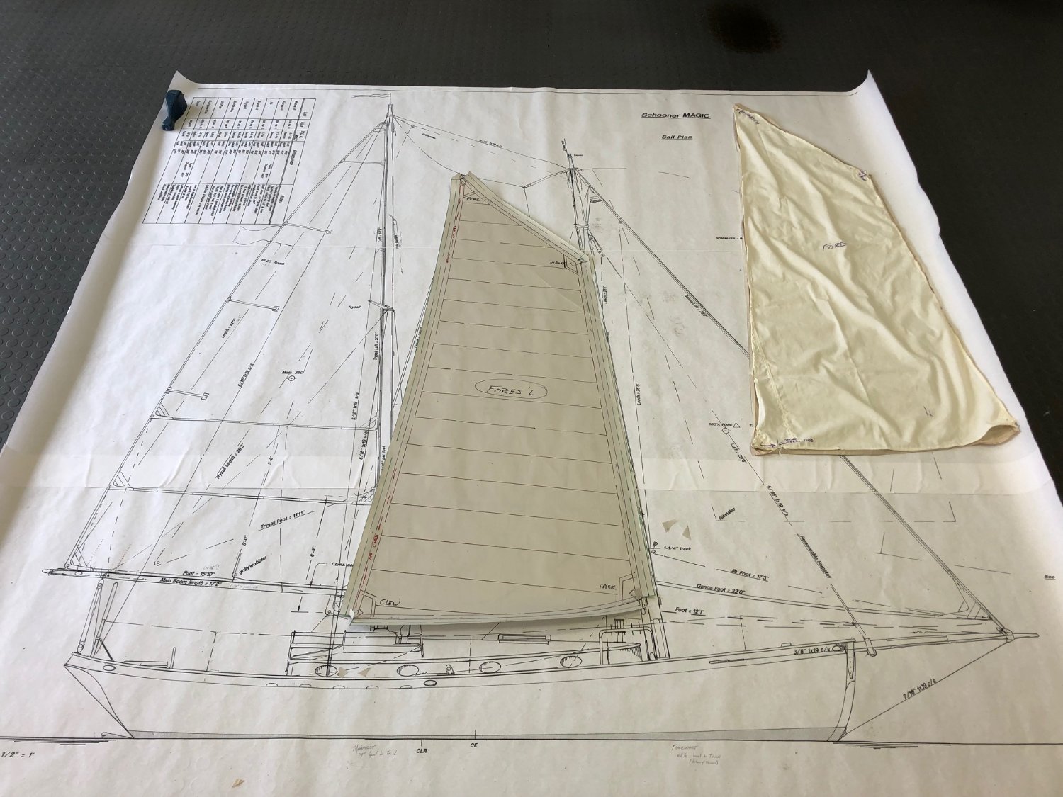
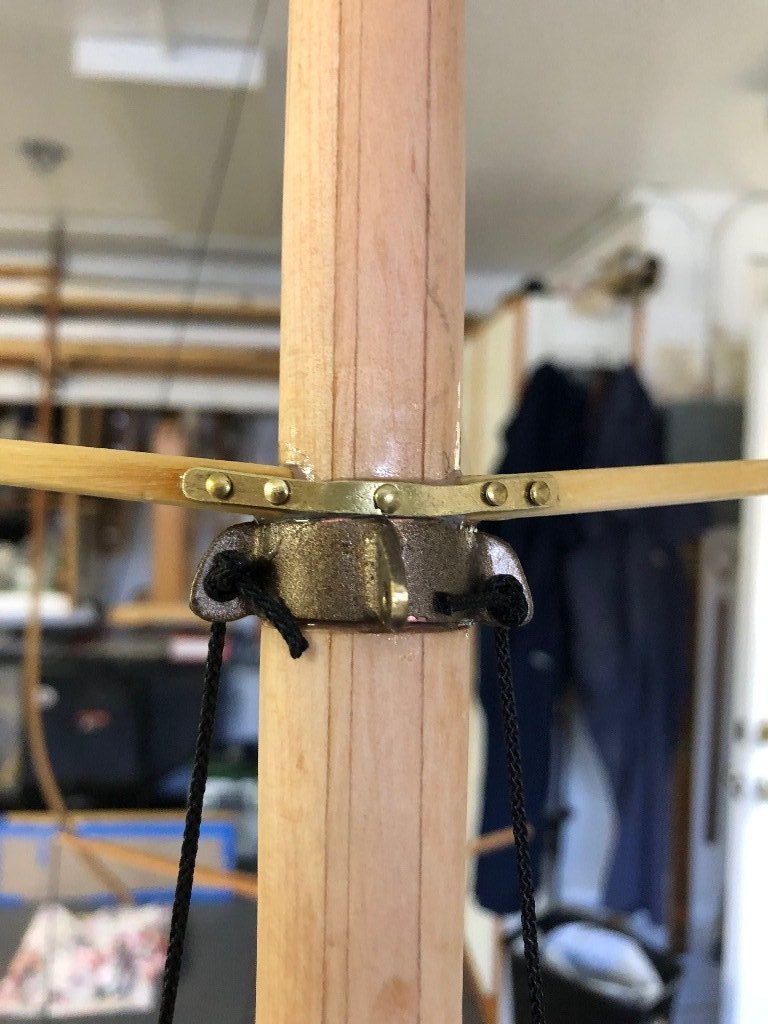
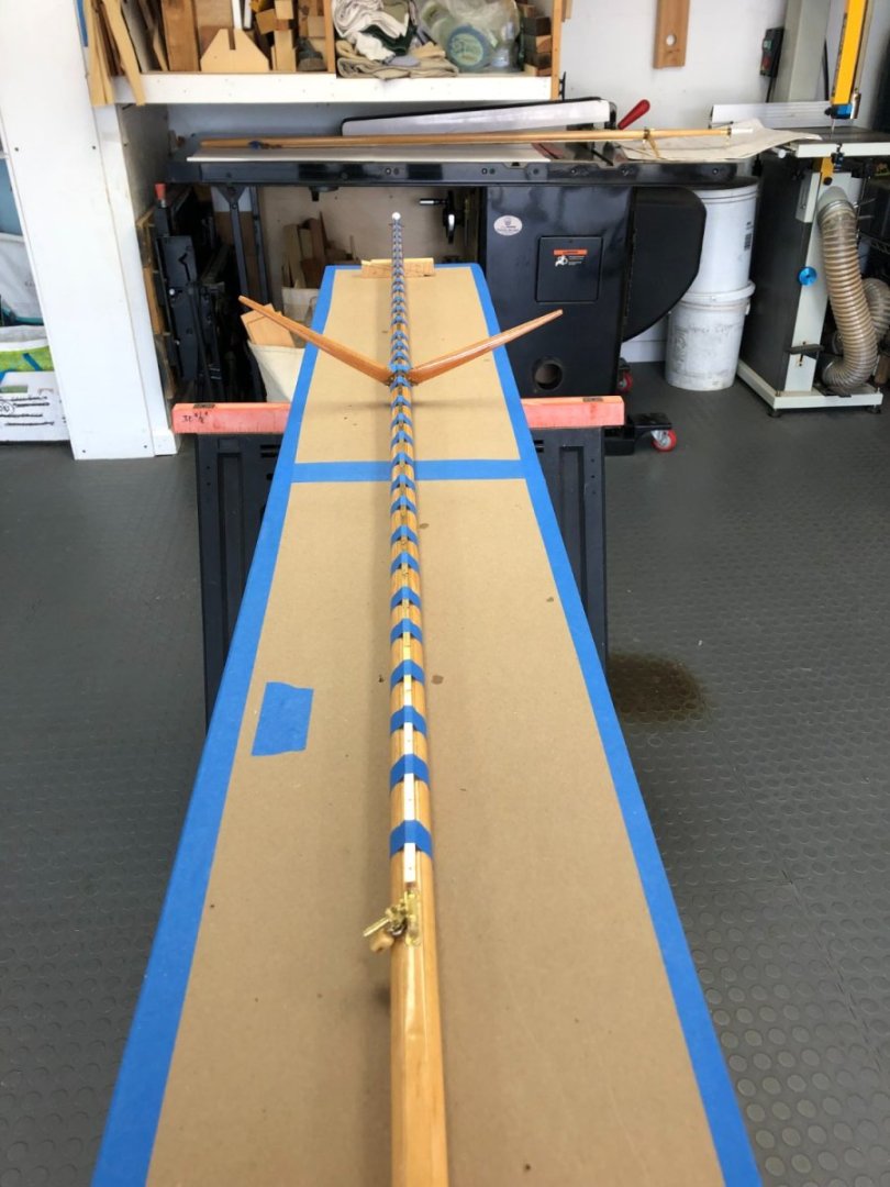
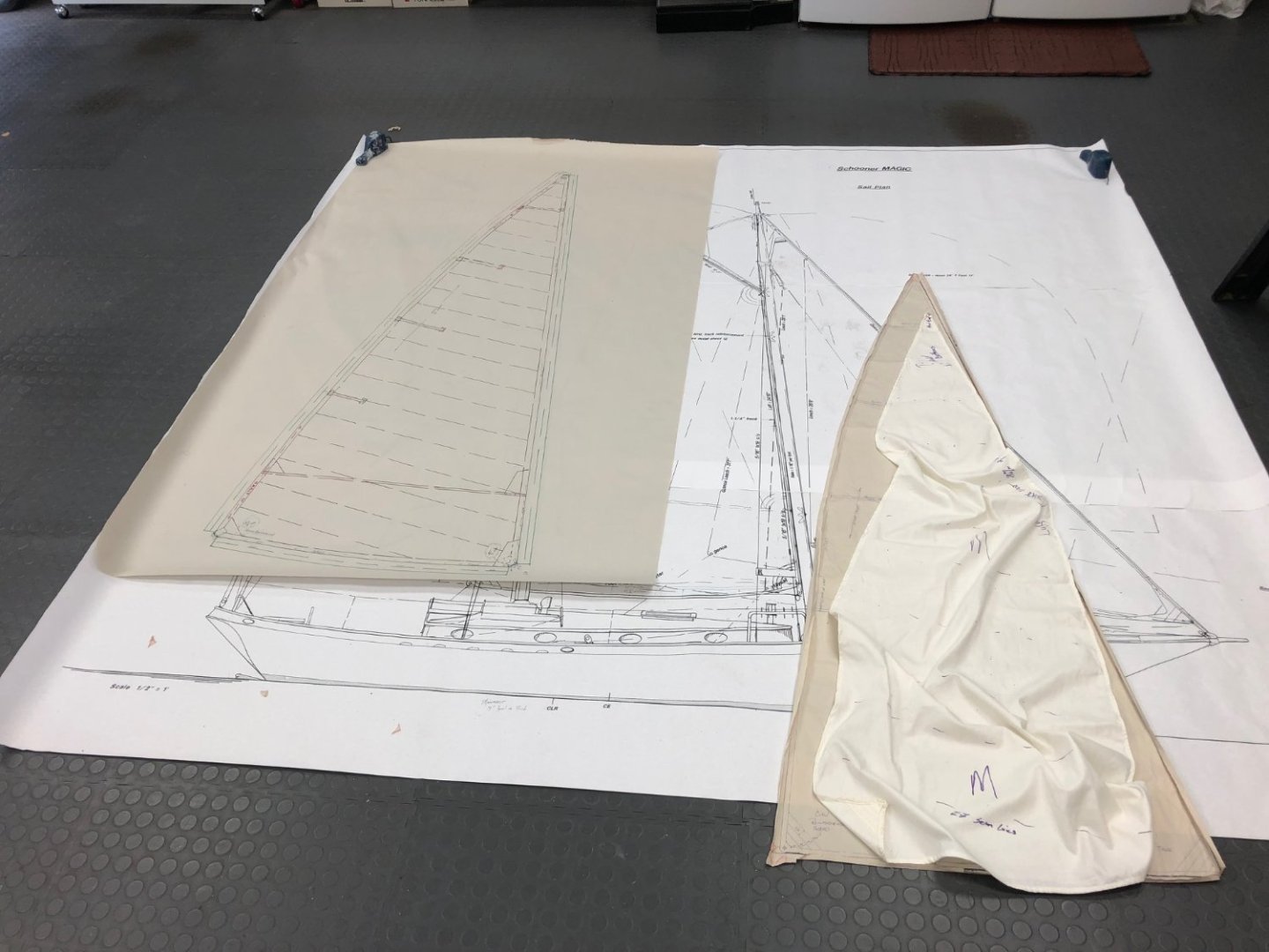
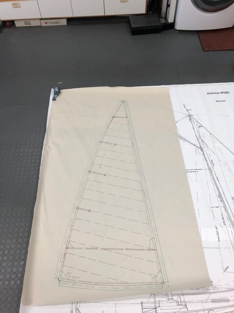
The masts were fitted with their respective mast bands, spreaders were made for both masts and MAGIC was again moved outside to permit stepping the masts. I used some black fishing twine as temporarily standing rigging and this permitted double checking the sweep and lengths of the spreaders. The spreaders were then strapped and glued to the masts. The mainsail and the gaff foresail would use slides along their luffs, so tracks were fashioned from brass flat bar positioned on meranti "battens or feathers". The sail slides were made up from hollow rectangular brass extrusions (which were a slip-fit around the brass flat bars). The extrusion lengths were placed in a tight-fitting groove cut in the bottom of a length of wood. The wood and extrusions were (carefully) passed over a partially-raised table-saw blade. This left a narrow open slot in the bottom of the rectangular brass which could accommodate sliding along the track-supporting feathers. The extrusion was cut into short lengths and bails of 1/16" dia. brass rod were bent up to be soldered to the aft faces of the slides for lacing on the sails. Meanwhile, a neighbor (who quilts a lot) asked if she could help out: "Did I need any sewing done?" Why, as a matter of fact, I did! So we agreed that if I traced off some paper patterns of the sail shapes, she would whip up a trial set of sails from spare bedsheet cotton. It of course seemed like a good idea to double check the sails derived from the original drawings against the actual model's rig, so I crawled around on the shop floor for a couple of days making patterns and then turned them over to her. In very short order, this trial set of sails was sewn up and delivered. This turned out to be a very necessary exercise before tackling the construction of the "final" suit of sails because there were several adjustments required to fit the spars and sheeting angles. Thankfully, we both enjoyed the process and Sally, the quilter, was eager to get on with the slightly heavier, revised sails. I made new revised patterns and off I went to a fabric store to find a more suitable cloth. <More to follow another day.>


-
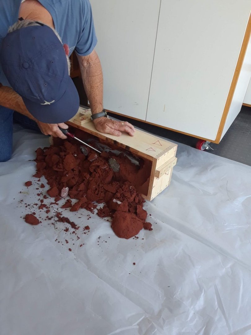
Roger: What Bob said. I ended up reading mixed reviews about the kitty litter mixture so I used a pre-mix from a foundry supply house. This mix tamped down quite firmly and permitted the pattern to be extracted without the void which the pattern created crumbling excessively. Now, I do have a very heavy 3 gal paint bucket of the stuff sitting around, but I may need to cast a lead 6L3 Gardner diesel as ballast for the next model... 😉
-
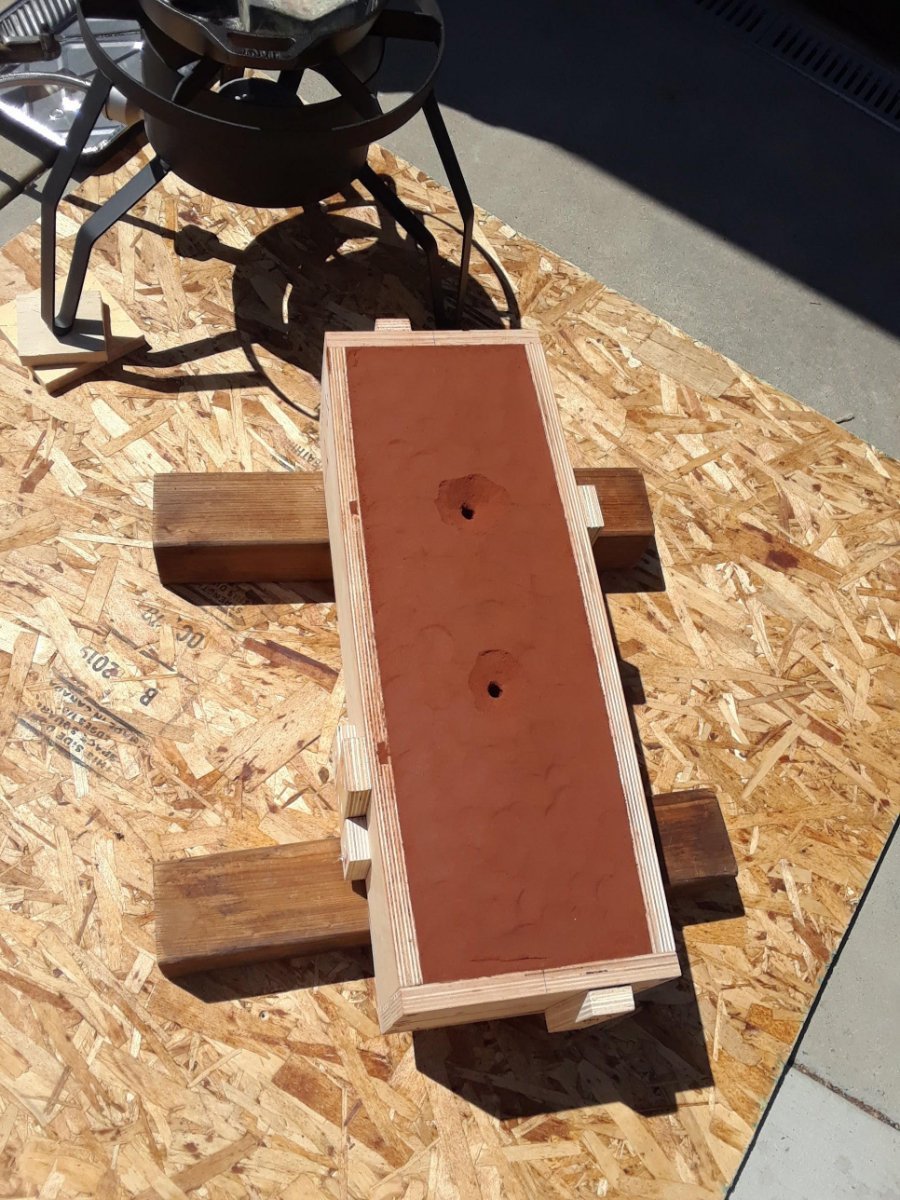
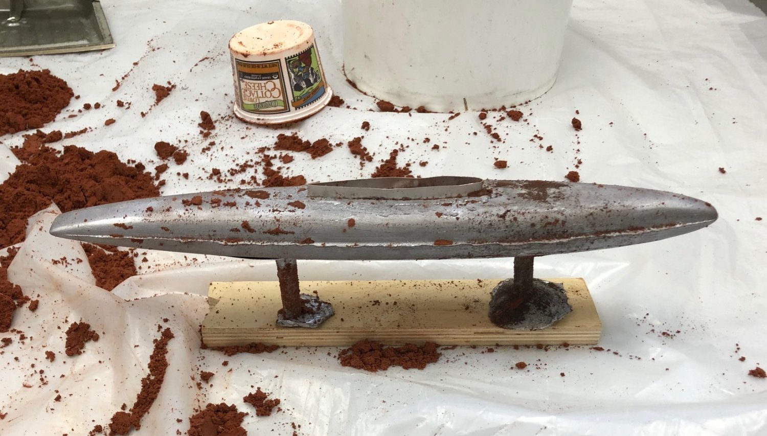
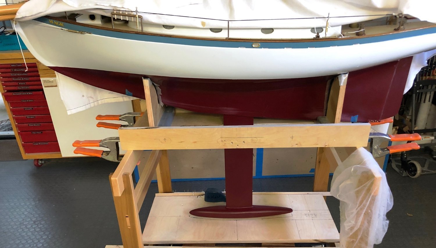
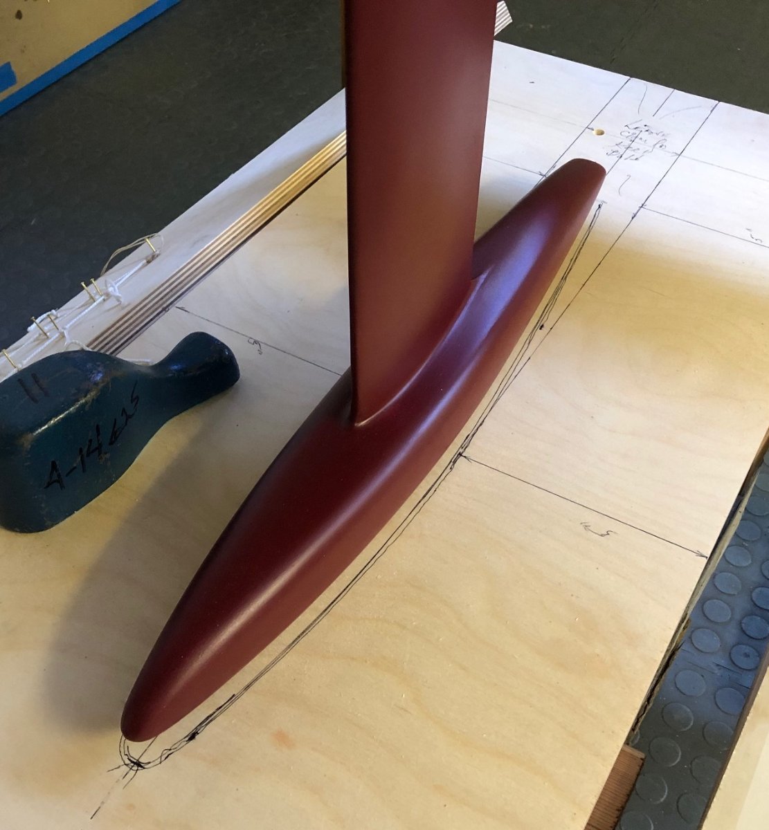
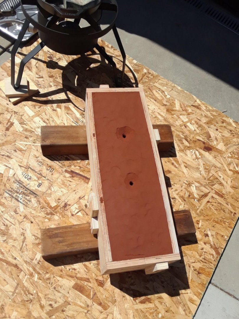
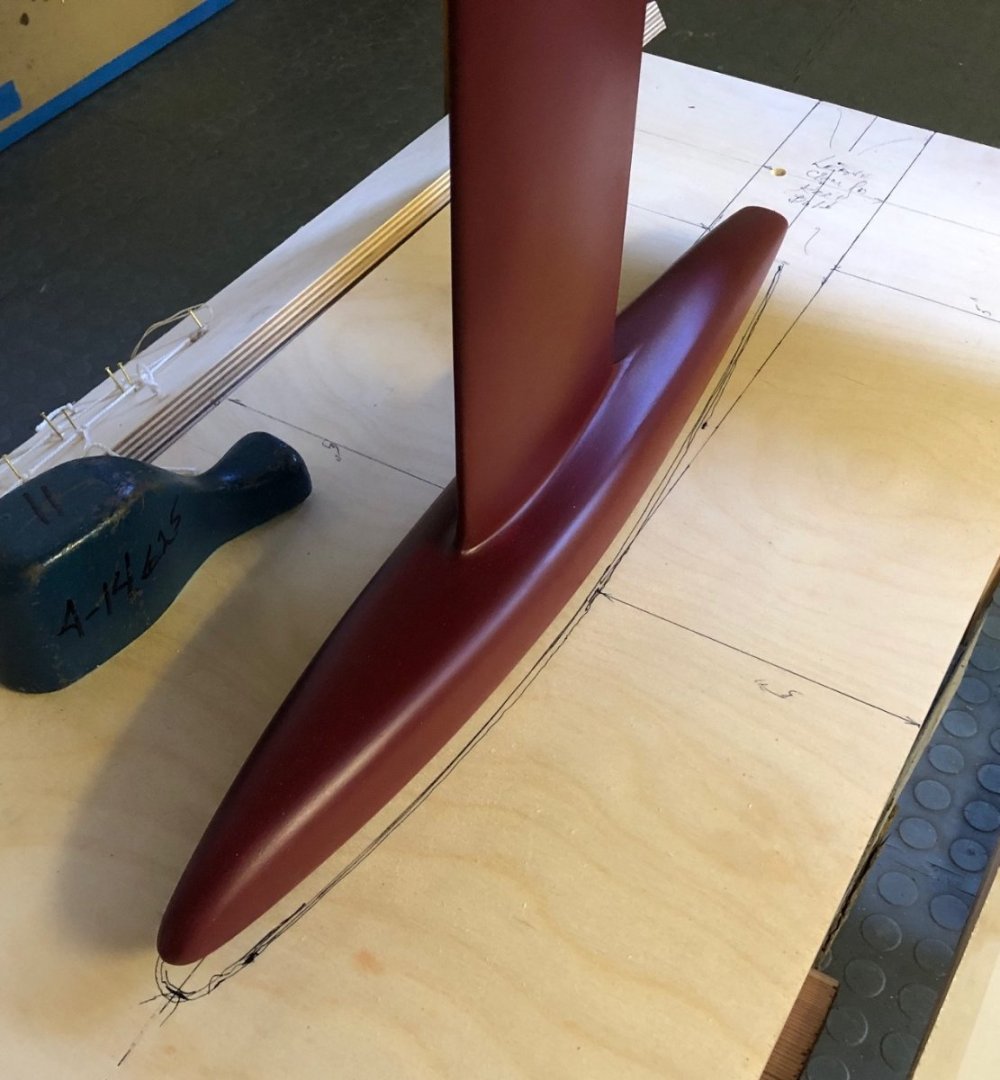
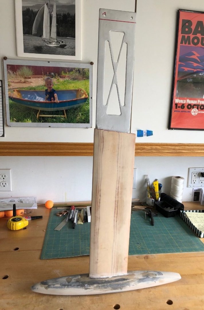
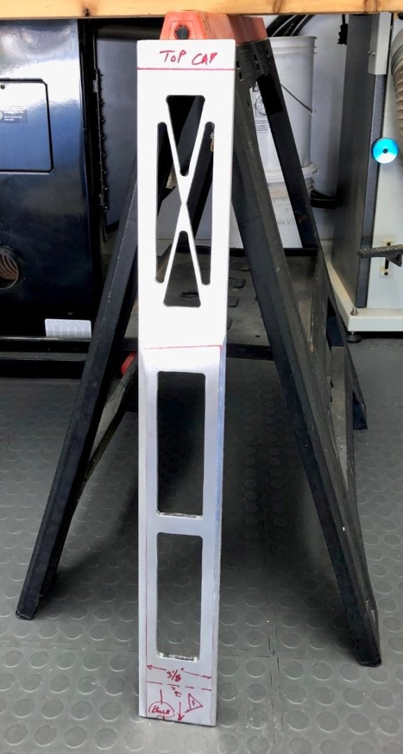
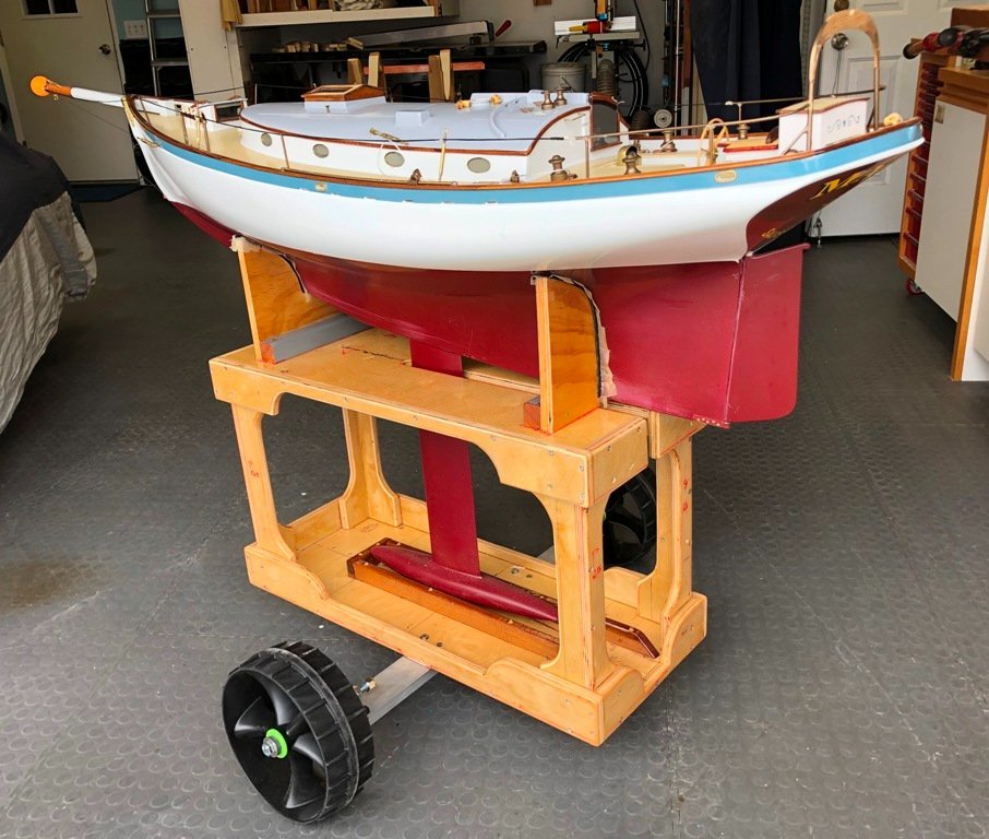
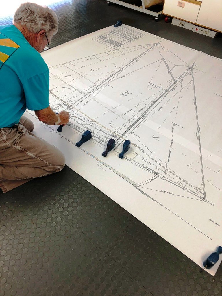
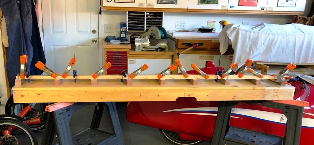
I took the information from the float test and ascertained that the lead bulb for the keel should be close to or at 15 lbs. The next step was to determine how big the pattern would need to be to serve this purpose. I cut a piece of Western Red Cedar to a precise 2" x 3" x 12" size and weighed it on a digital scale. Calculations showed what the same size chunk of lead would weigh and the ratio between the two would permit me to whittle down my wooden design shape for the casting pattern until its weight times the ratio would equal the needed weight in lead. Once the shape would yield the correct weight, I was also able to create the necessary sized cope and drag "boxes" to hold the sand for the lead pour. After ramming the sand around the pattern and then removing the pattern, cutting vent and pouring sprues, we were ready to heat the lead and pour. The result was decent enough to use and the center foil-shaped knock out was eventually convinced to exit. I purchased a piece of aluminum plate (5/16" x 4" x 32") to use as the core for the keel bulb supporting fin and after some measurements were noted, I cut away portions of it to minimize the weight of the fin itself. The cutouts in the lower portion were filled with basswood, the fore and after edges of the plate were ground down to get rid of the rectangular shape, and then a couple of layers of the 3/32" thick plywood were laminated to the sides. The fin was shaped to a close approximation to a NACA foil, faired and then covered with fiberglass cloth set in epoxy. The tight-fitting bulb was bonded to the bulb with epoxy. The combined weight of the boat and the keel would ultimately be 41 lbs. and I realized that some form of a launch cart was going to be necessary to avoid serious back issues picking her up or putting her in. With the keel now able to be put in place, a launching cart design came together (somewhat inelegantly) from odds and ends in the shop. An extendable baggage cart handle was added later to avoid reaching under the bowsprit. The hull, with its keel, was intended to slide aft off of the submerged cradle, with the keel fin slipping through the upper slot of the cart. (Note to self: wooden carts may float which is not always useful.)Rigging and sails were next.


-
Thank you, John for the kind words. I am delighted that you and others are enjoying the build blog. The expertise in these forums is an inspiration (and humbling). I am delighted that Bob Cleek posted a link to Michael Mott's project some years ago because Michael (and several others) set fine standards for quality and precision.
-
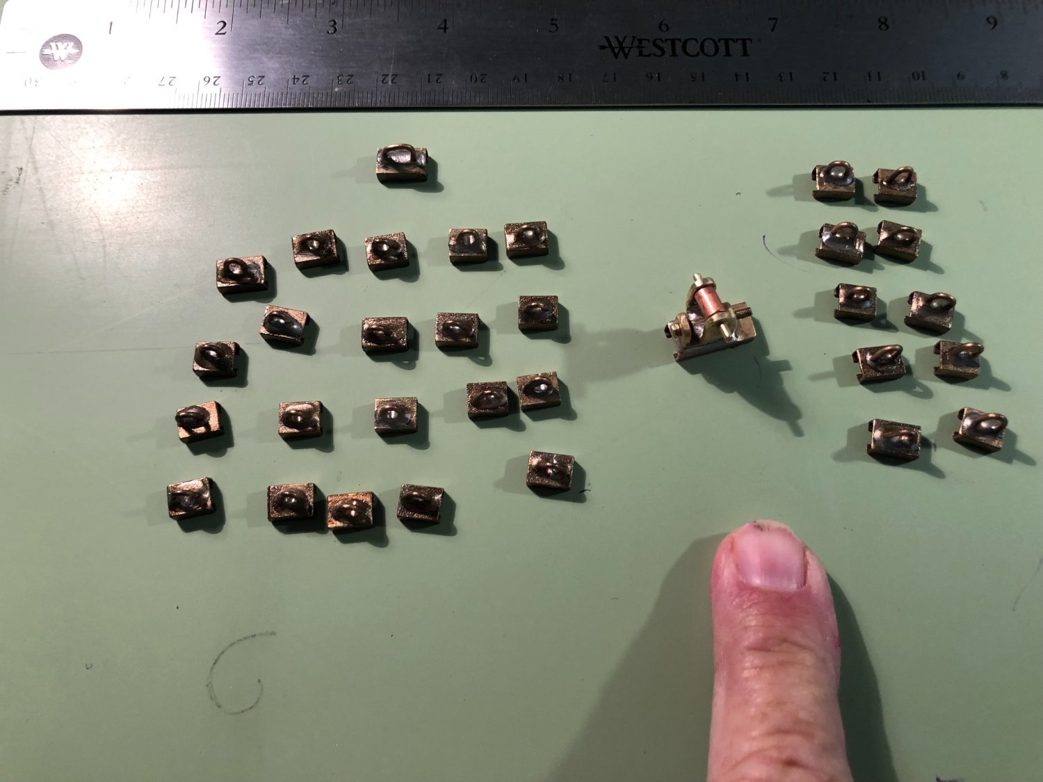
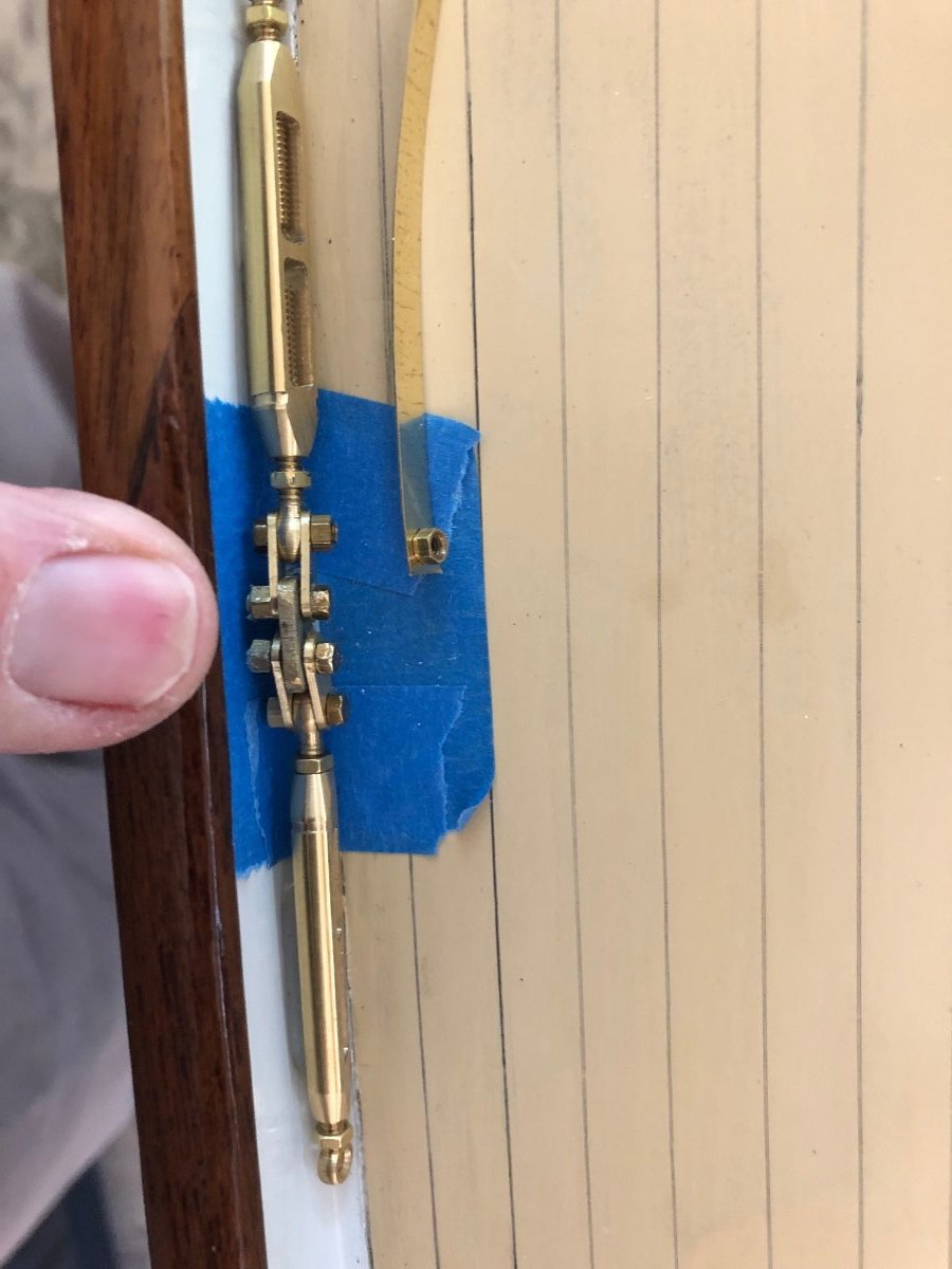
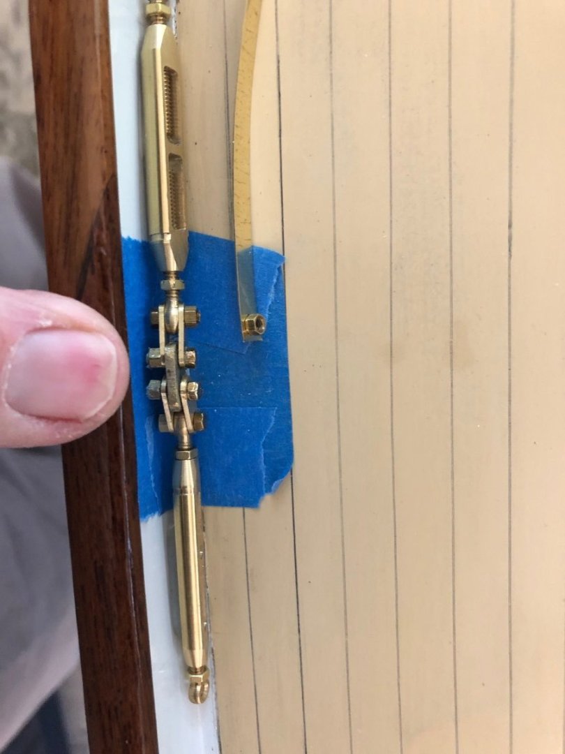
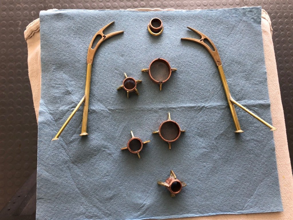
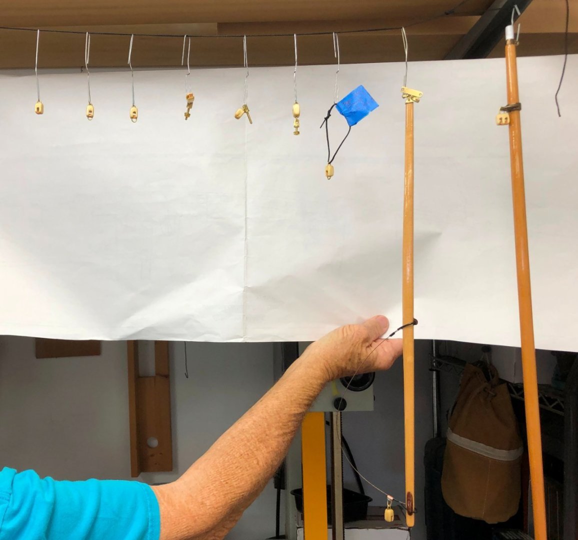
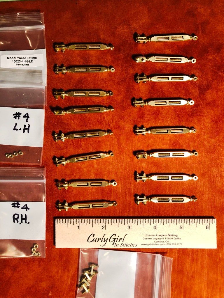
To finish up today's posting, I will add some photos of hardware installation. The boom gooseneck (and later, the gaff car) came from a retired USCG man living in Florida who was manufacturing brass sailing hardware. The rest of the hardware, such as the pinrails, stanchions, sway hooks, tracks and sail cars were efforts on my part. (I certainly hope to acquire a small lathe prior to the next model...) I used a drop of CA glue on a brass strip to hold the #2 nuts in alignment while tightening the turnbuckle mounting bolts. I confess to a fair amount of frustrated swearing during this exercise in patience. Until again.
-
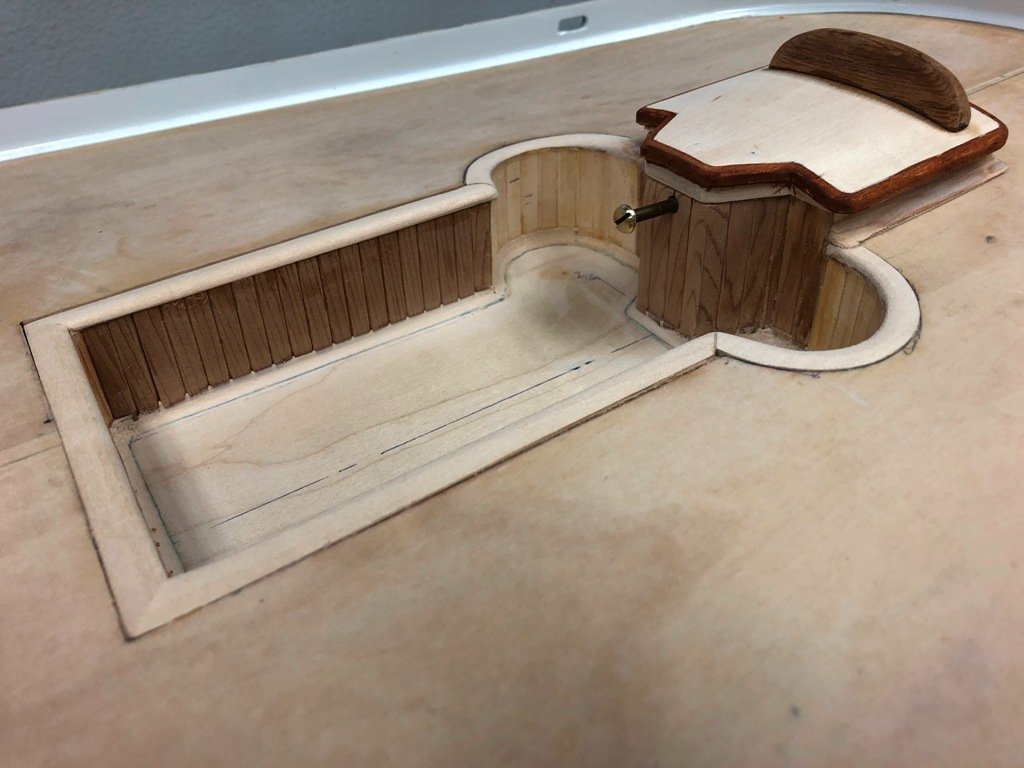
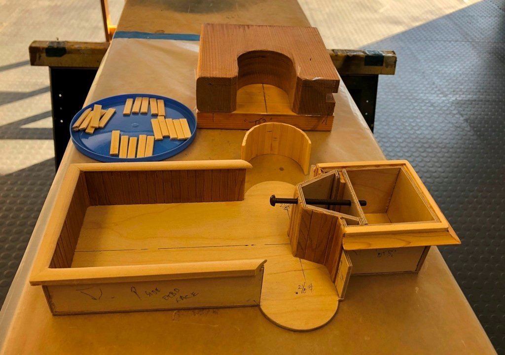
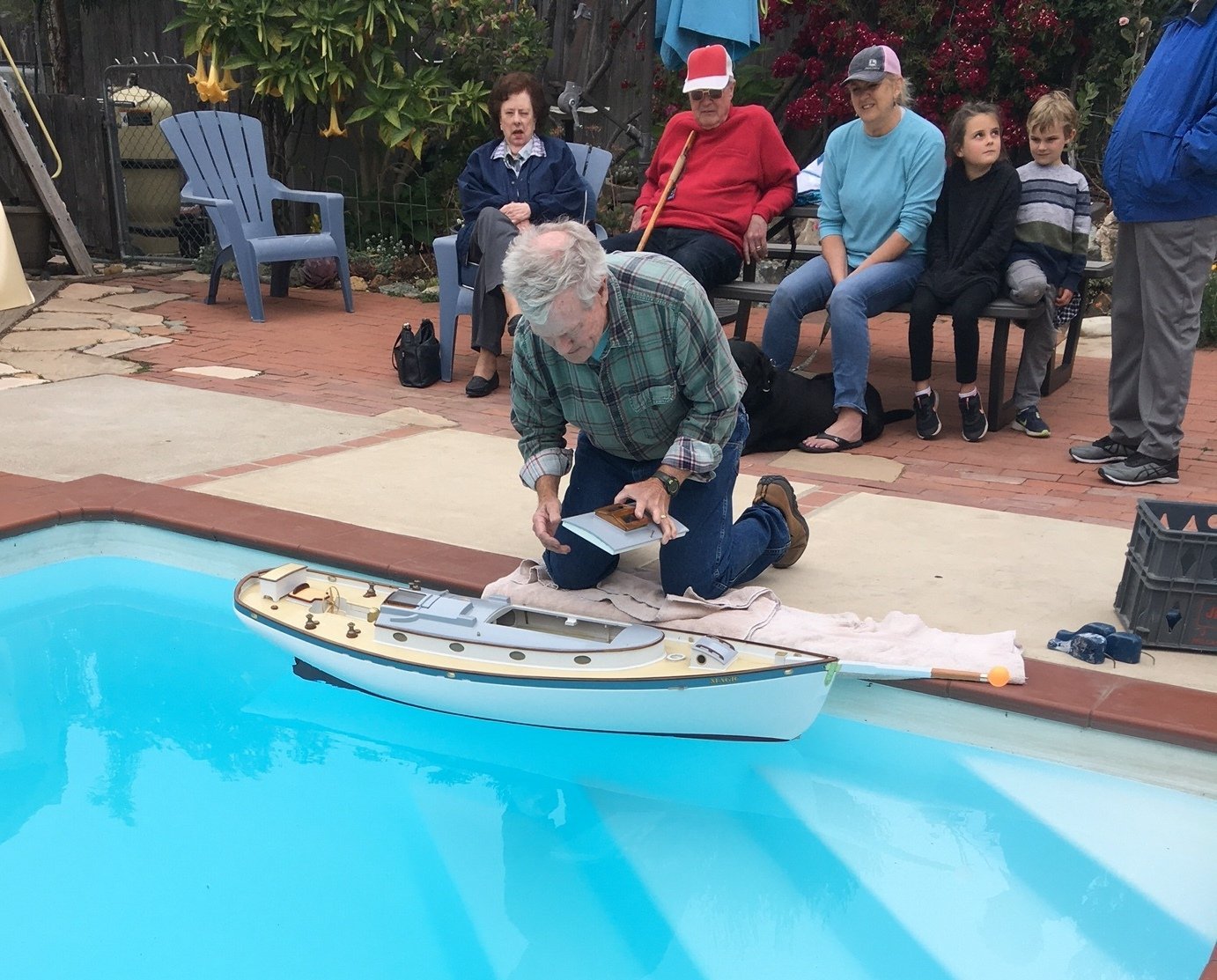
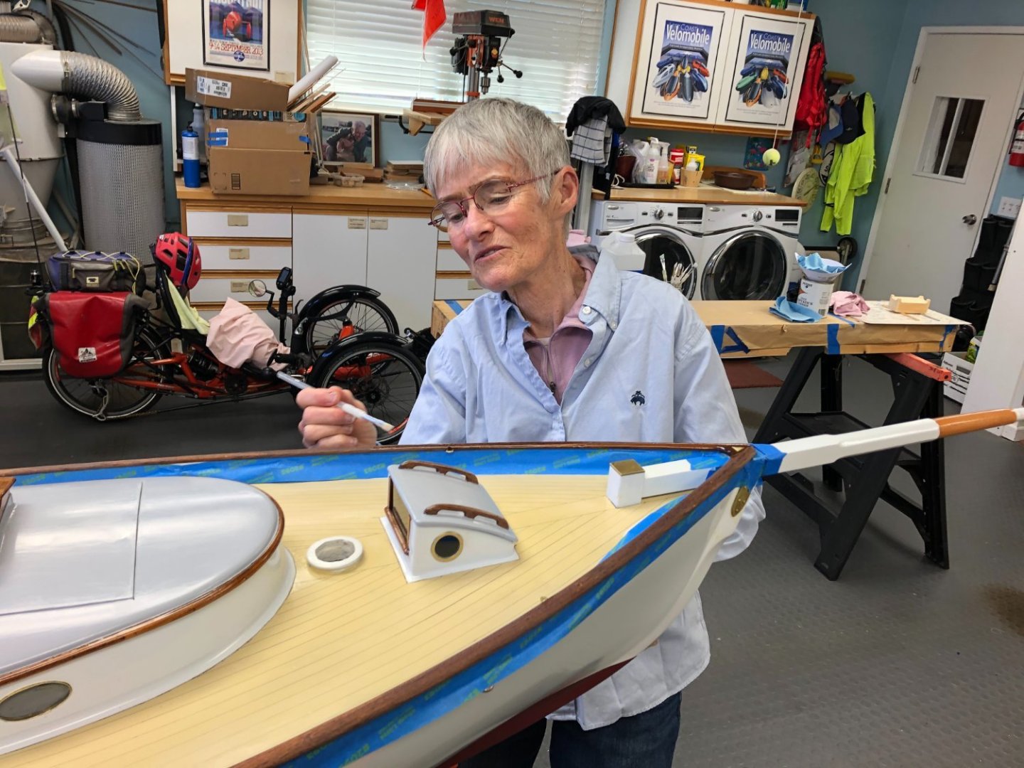
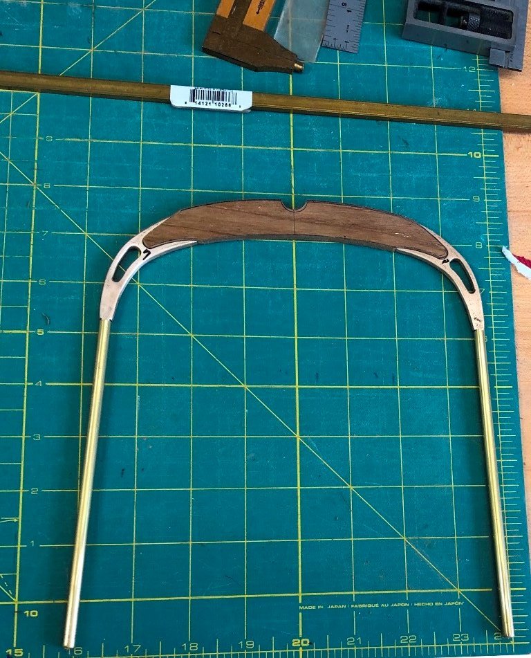
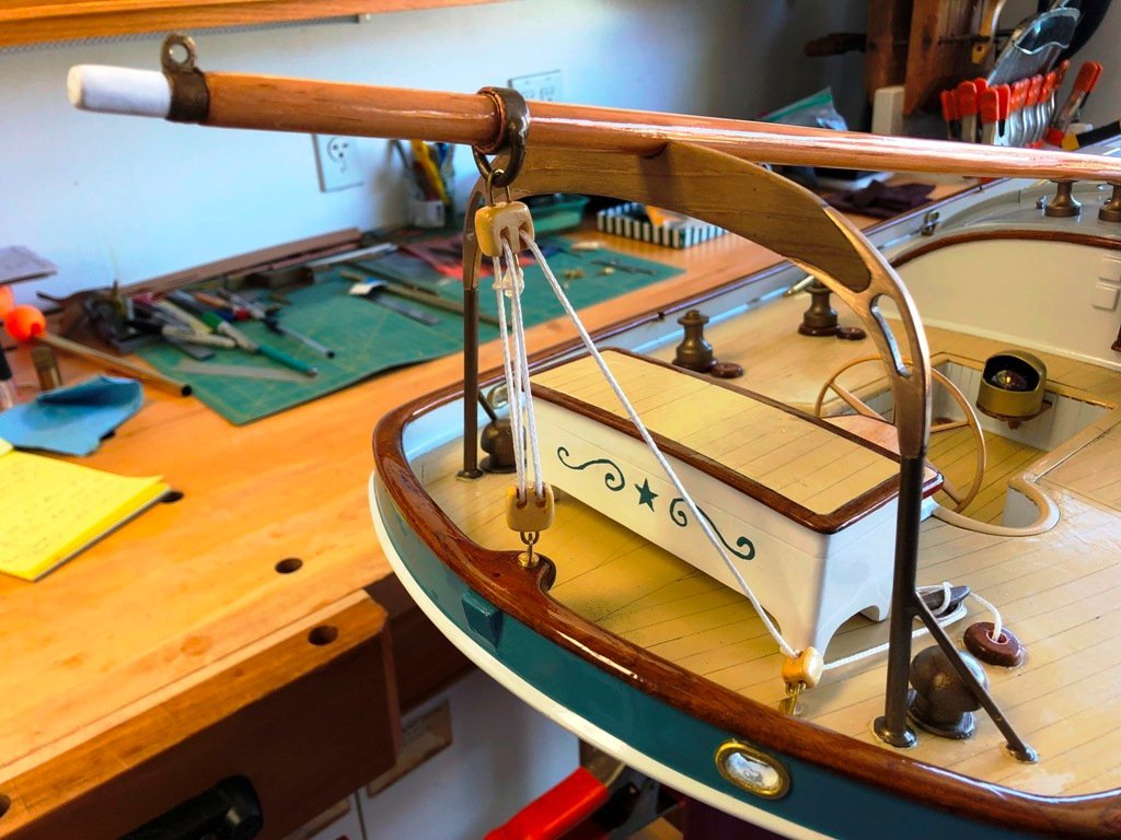
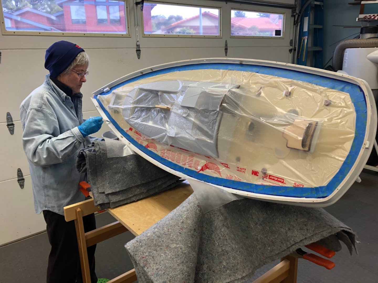
While Vicky continued with her detail varnishing, I made arrangements to visit a neighbor's pool to conduct a displacement and trim check. The boat was weighed on a scale beforehand without ballast or rig and then at the pool, calibrated weights were added into the bilge to bring her down to her waterline. Weights were also adjusted fore-and-aft to tweak the trim. Allowing weight for her rig and sails, most of the remainder would be configured into her ballast bulb. (Yes, I did factor in the difference between freshwater and salt water buoyancies.) The aft-mounted propane locker - carved from a block of AYC with teak trim - had been finished and mounted by this time. I was pleased that the location of the ballast keel trunk proved to be in the correct fore and aft position. After the float testing, MAGIC returned to the building cradle for more work. I built the hollow spruce masts and once shaped, we trial fitted them to check rake angles and standing rigging lengths. Here, the glued mainmast is curing and the early stages of the boom gallows fabrication from brass tubing, bronze plate and teak is shown. More bits of hardware The boom, gaff and a variety of blocks were made and varnished The turnbuckles arrived from Florida and the mainsheet arrangement was trial fitted. The first "raising of the masts" showed that the rake angles needed a bit of tuning.

-
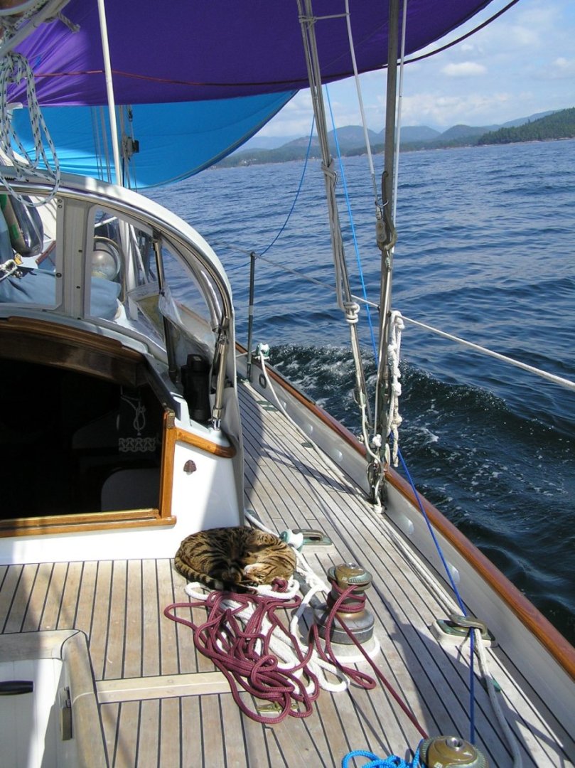
That character was Archie, a male Bengal who loved being on the boat, but also loved serving as a figurehead on the Shellback dinghy when Vicky would go for a row. A bit of a sensation in an anchorage.
-
Hermann: I used an older plastic drafting spline (which happened to be the correct width) for inking the deck planking strakes. MAGIC's deck planking was laid to follow the curve of the sheer, intersecting the king plank at the end of the runs. The first line was drawn one spline width inboard of the covering board, with the spline held in position by lead "ducks". I did one side and then moved the spline to the opposite side of the deck to do the matching line. The longest lines were these outer lines. When the "permanent water proof" ink dried, I moved back to the first side and used the spline width to space for the next inboard "seam". Back and forth between the two sides. Before too long, the spline was too long to fit onto the deck without interference from the bulwark on one end or the other. So, I trimmed it shorter. Once the side decks had been marked, it was necessary to use shorter pieces for the bow and stern areas. Not too surprisingly, any small errors in width spacing were magnified from port to starboard as the longer angled ends met the king plank, so some subtle adjustments to the widths were made to minimize the visual discrepancies. While the finished lining out was lovely when new, I did not wholly trust the "permanent, waterproof" claims and decided to lay a thin coat of varnish over the painted, lined-out deck. Over time, the lines have faded noticeably. So, perhaps not the best choice for a deck planking lining-off method.
-
CCoyle: I grew up in Los Altos but the homeport was a quirk. Vicky and I had sold our home to pay for MAGIC but at the time the USCG required an actual seaport to be listed on the transom. Fortunately, my sister lived at that time in Sausalito and we used her address for documentation purposes. It seems that each of MAGIC's 3 subsequent owners don't want to change it.
-
Hang on, Bob. The answer shall become clear. Patience, my friend. 😉 (Yes to your question).
-
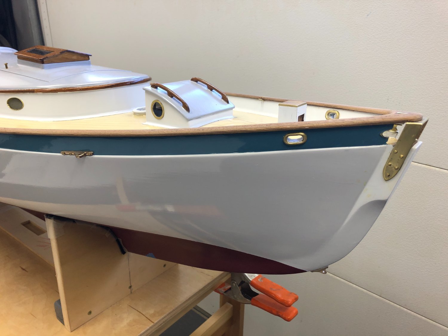
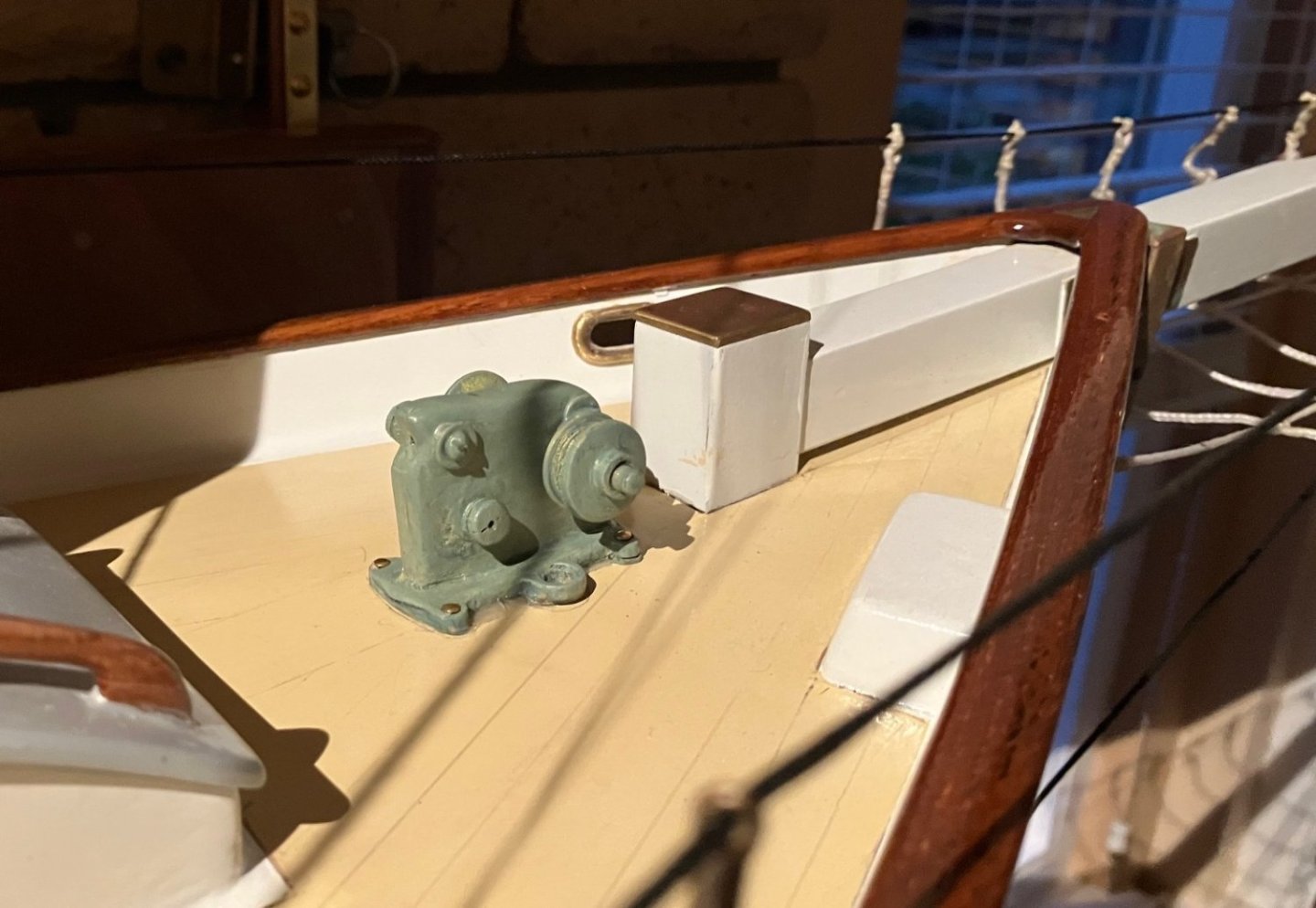
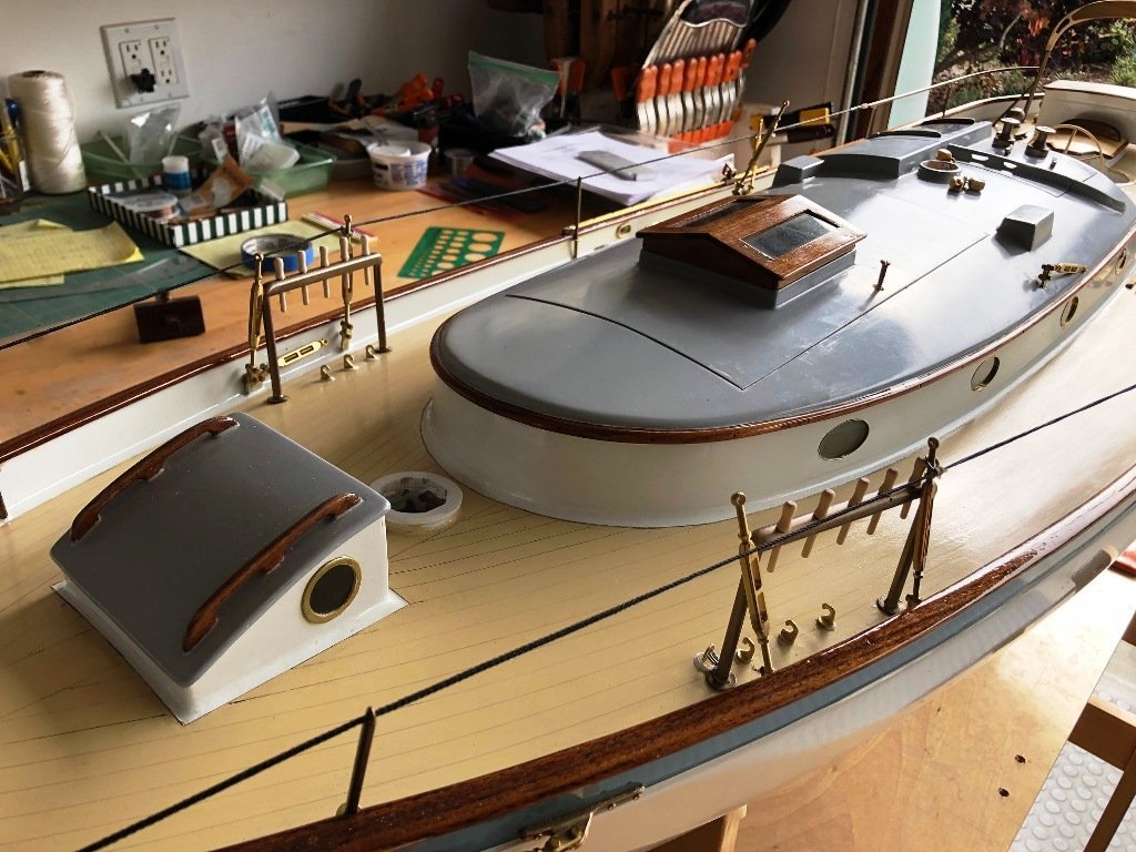
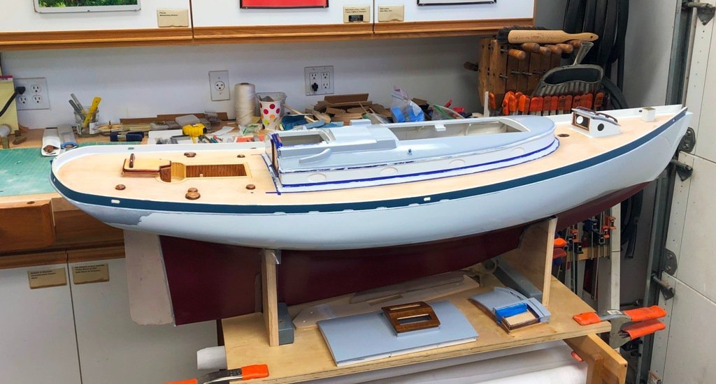
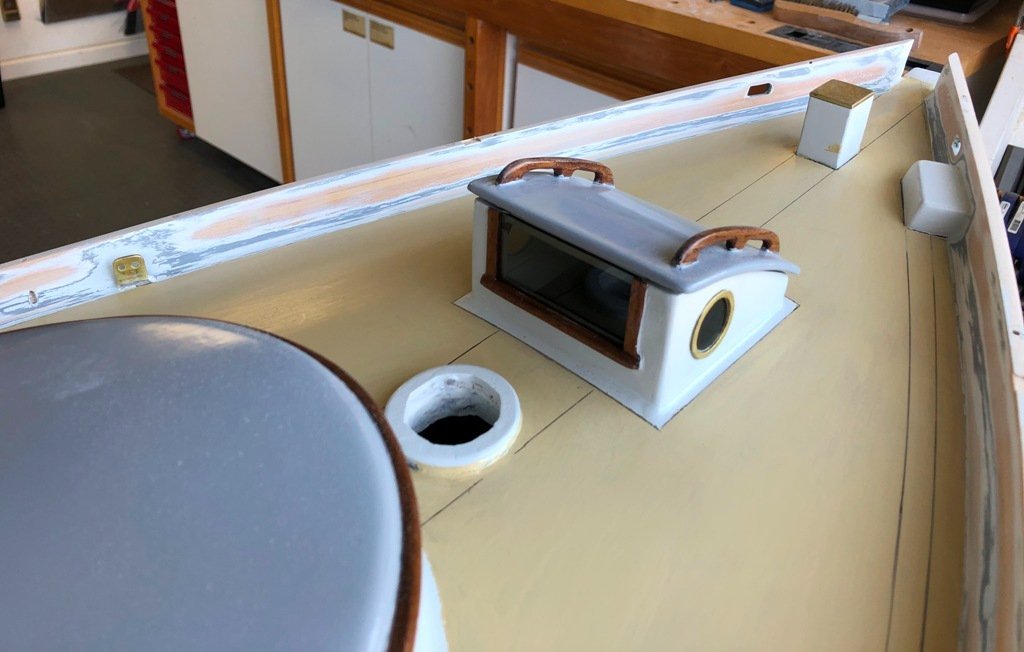
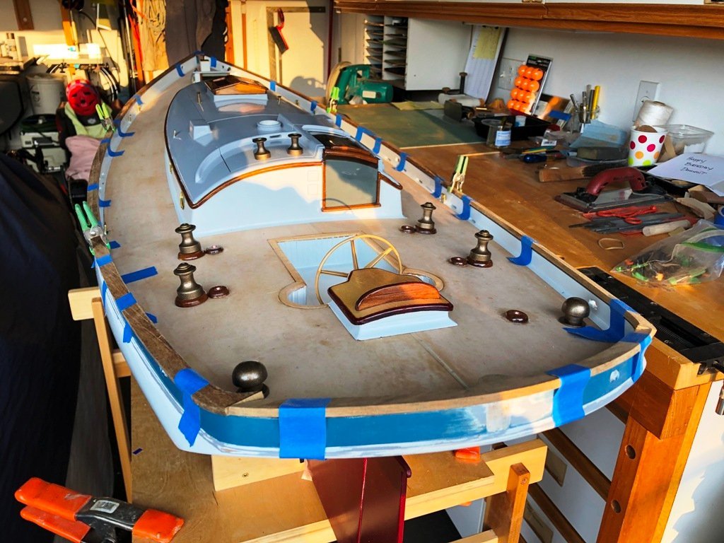
The next task in our sequence was to permanently glue down the house and work in a cove to transition from the deck upwards to the sides of the house. We also started painting the house and scuttle lid. Deck mounted winch bases were glued to the deck and a couple of "instrument" boxes were added to the aft face of the house. A rudder gudgeon was bent up and secured to the heel of the keel. And a mysterious box arrived from a cousin containing a selection of Barient-style winches which just needed a couple of coats of "antique bronze" paint. I decided that it made sense to refinish the topsides and bulwarks before we got too much further along, since the following step would be the installation of the bulwark cap rail. Prior to the refinishing, though, I took some time to fabricate the teak bulwark cap rail. This was scarfed together, shaped and then set aside until the sanding and painting was completed. These next two images show Magic in late February, 2021, with the cap rail in place, the deck painted "Alaskan yellow cedar", the plank seam lines inked on and a few extra bits of installed hardware. More to follow another day. Craig


- 67 replies
-
- 10
-
-
-
Thank you all for your kind words. Makes me almost want to do this sort of thing again... 😉
-
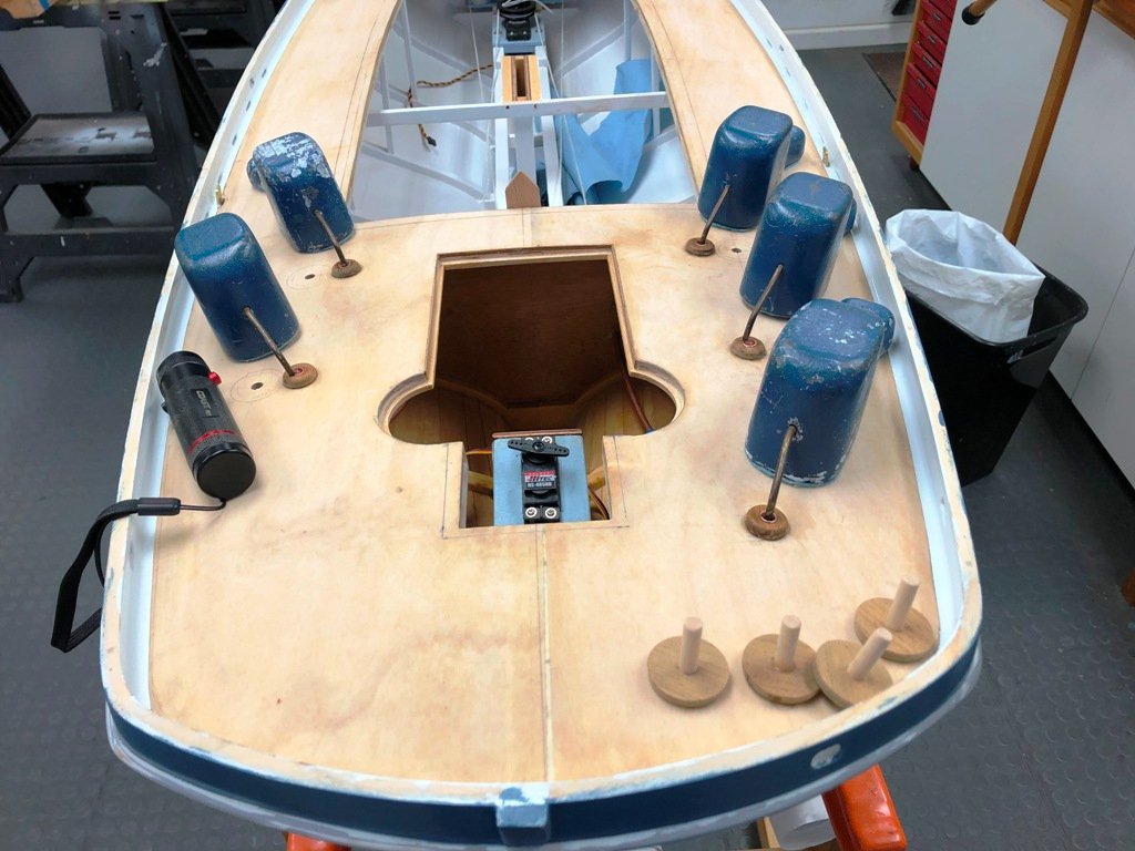
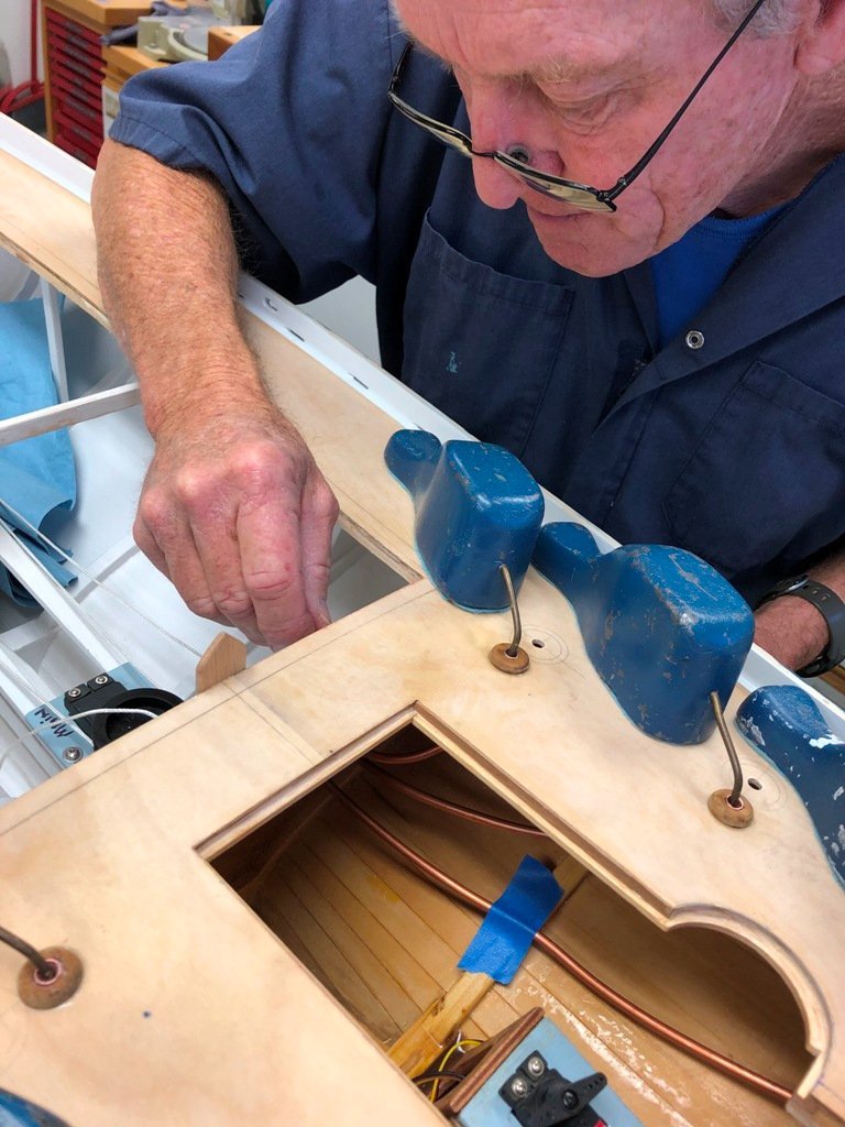
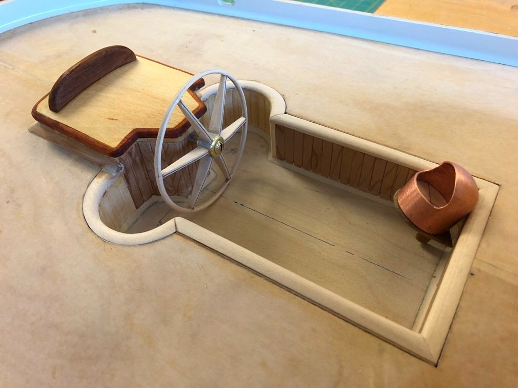
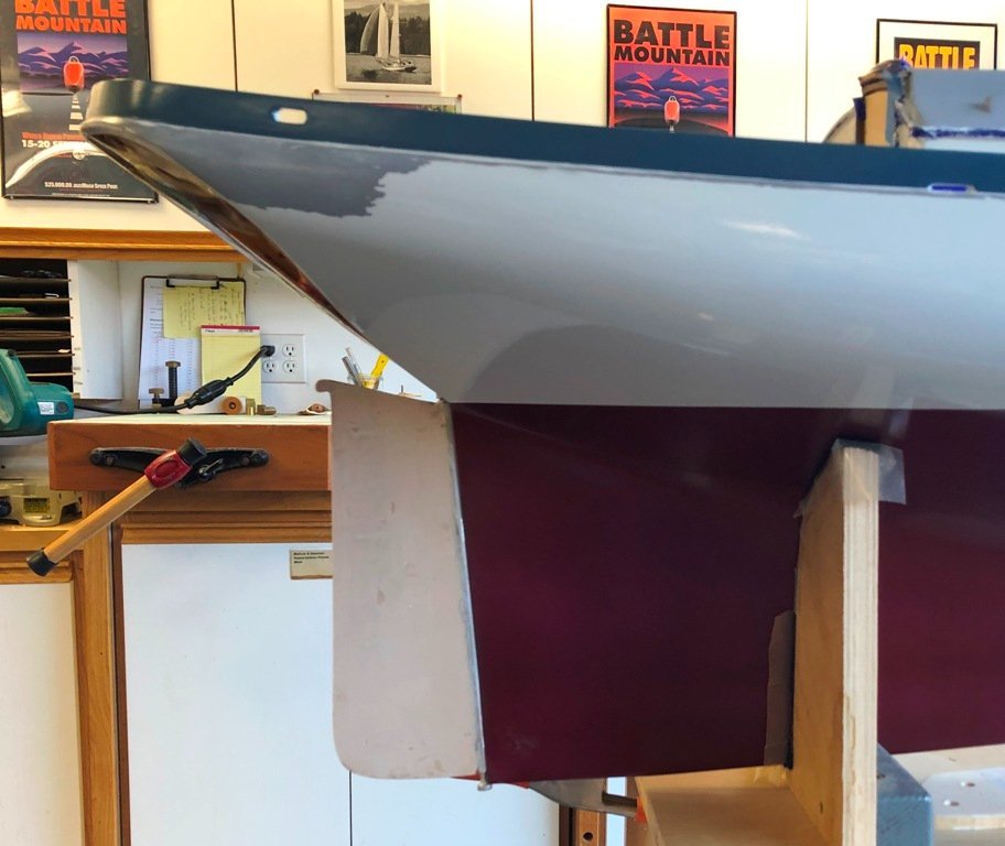
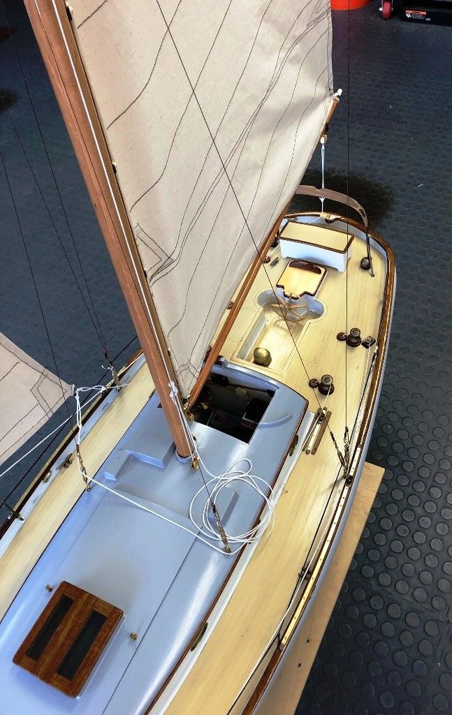
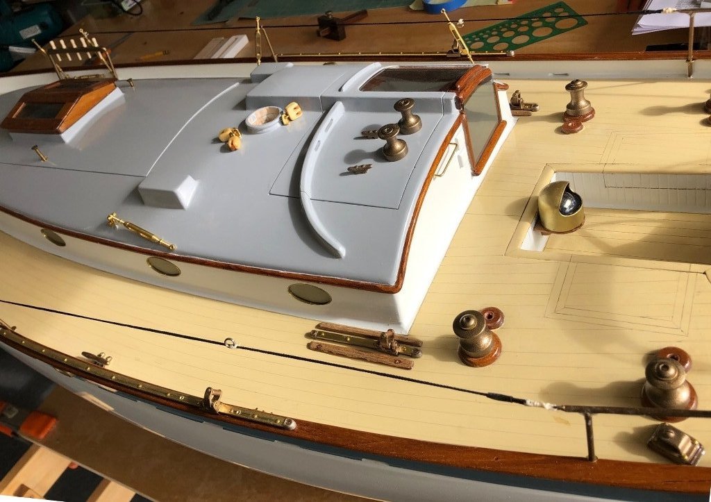
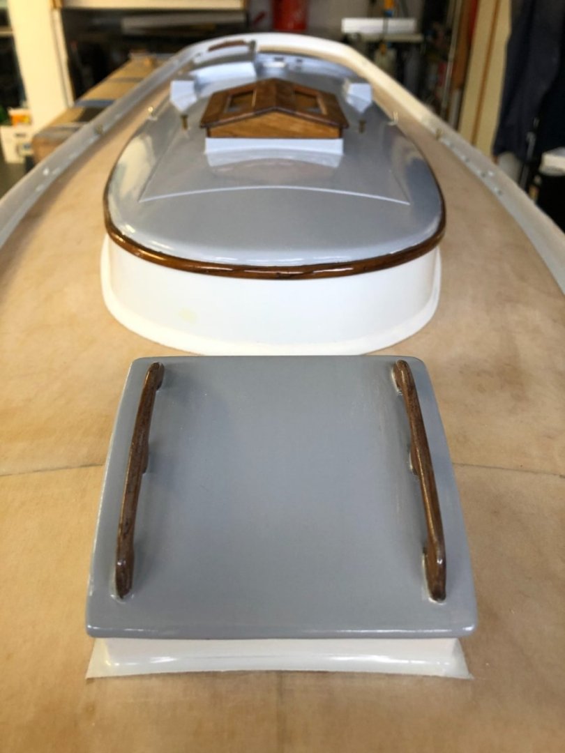
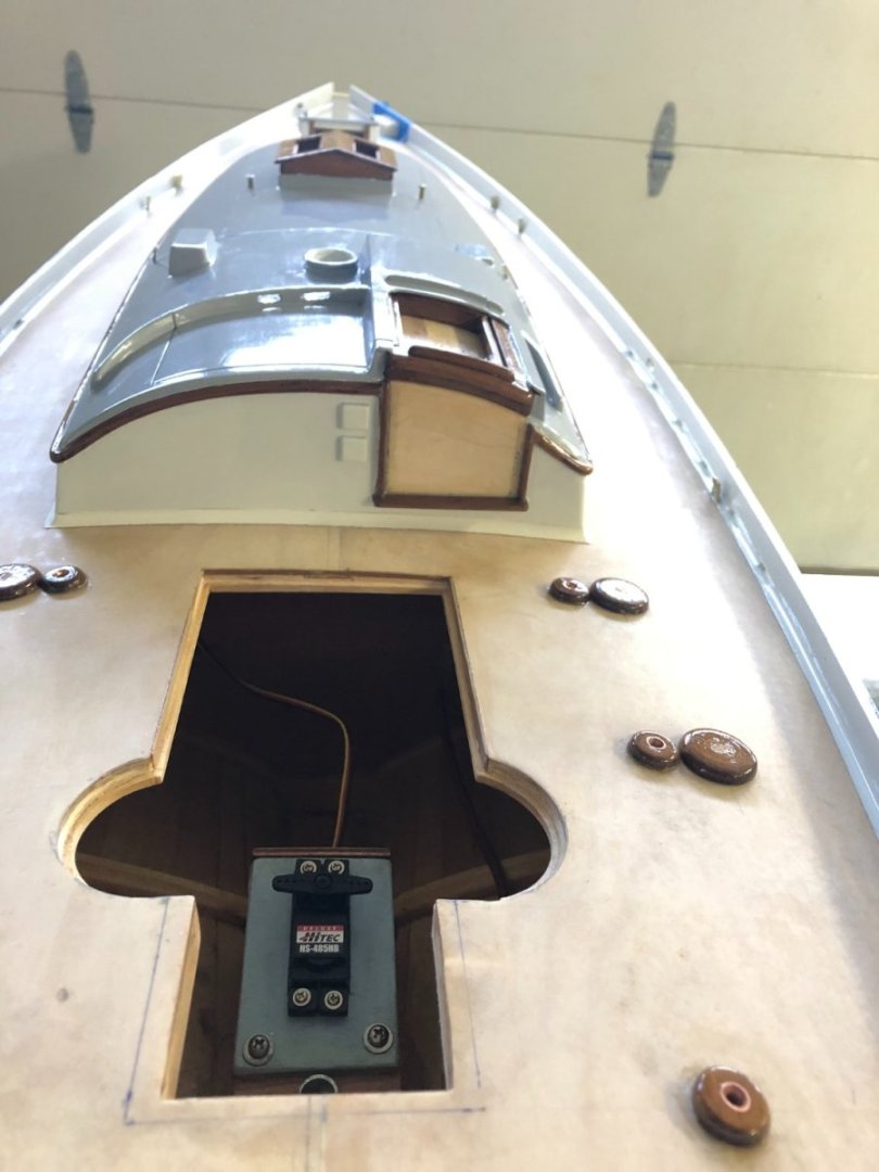
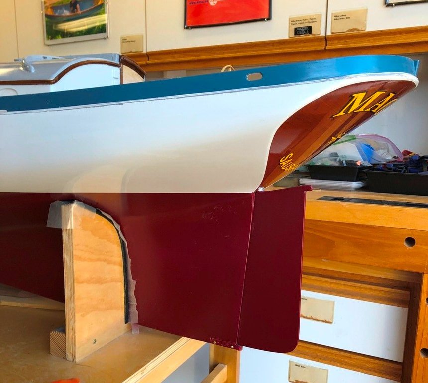
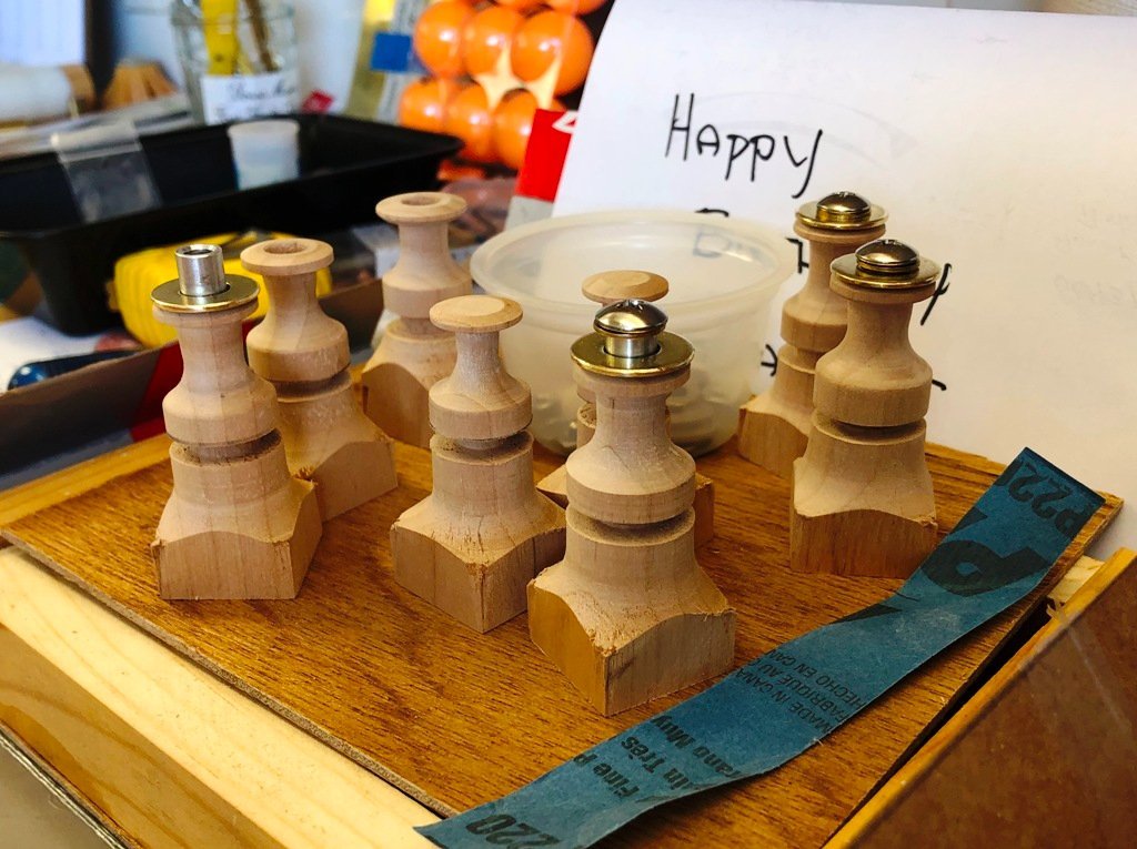
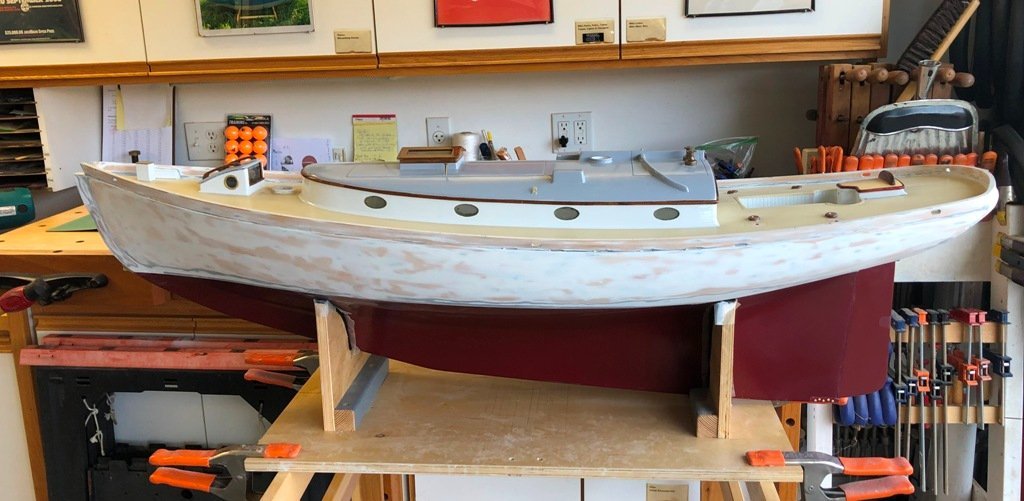
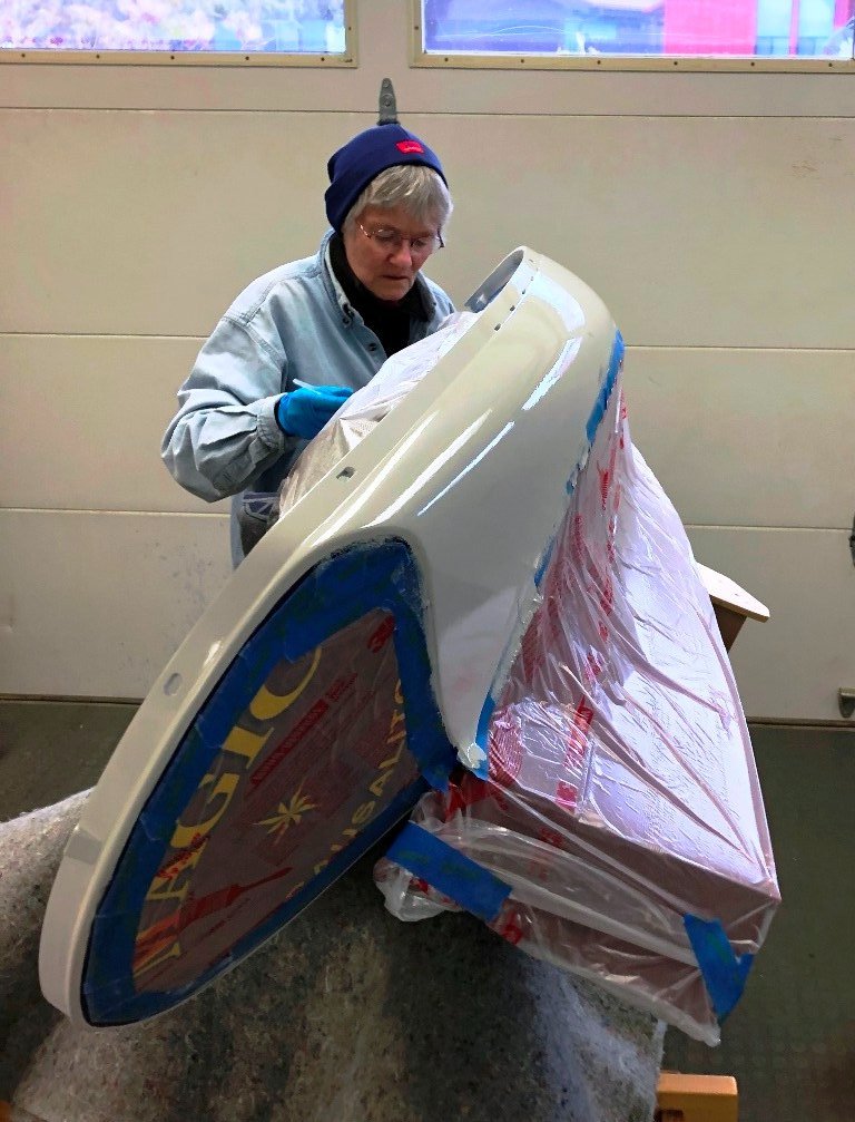
Before the house could be glued down, it was necessary to bend and fit copper tubes from the aft bulkhead up and through the deck near the future winch locations for the mainsheet, foresail and jib sheets to slide through. The cockpit is a removeable structure to permit access to the rudder and its servo. I strove to make it a watertight unit with a tight fit to the deck lip. The depth of the cockpit could not be scale directly down from the original schooner's "pit" due to clearance issues between the bottom of the cockpit and the rudder servo on the model. This also meant that the wheel needed to be slightly smaller. I took the inspiration for making the binnacle from Michael Mott's work on his lovely cutter, hammering this out from a copper plumbing cap and then finding a properly scaled marble to serve as the compass. Here it awaits a final positioning once the cockpit is finished. (She Who Has Steadier Hands is shown painting.) The rudder needed to be built and fitted up through the rudder trunk to check clearances: The topcoat-to-primer lack of adhesion can be seen above right. I eventually had to strip off the white top coat and a hard automotive grey primer before re-painting with a marine primer and topsides paint. So we learn.