MAGIC's Craig
-
Posts
135 -
Joined
-
Last visited
Content Type
Profiles
Forums
Gallery
Events
Everything posted by MAGIC's Craig
-
 I join the others in wishing both of you the best results and a return to easy health. Your model creations and teaching tips are a great boost to all of us who follow along. Press on! Craig (and Vicky) Johnsen
- 732 replies
-
- 2
-

-

-
- Lula
- sternwheeler
- (and 1 more)
-
Thank you, Gary. We originally cruised with little (or no) power aboard, so charts, dividers, a bearing compass and a lead line were the rule. With time and the increasingly more capable chart plotter/radars, we came to appreciate the accuracy of these devices, but at Vicky's insistence, we also always kept the current chart out just in case the electrons ceased to flow. The folded chart on the chart table is the relevant one for that shown on the plotter. These details are fun to include.
-
To John and both Keiths, my thanks for your thoughtful compliments. I have been very fortunate to have had her support and interest for over a half century. And for those folks who also checked in, we do really appreciate your endorsements. They serve to inspire the work and for me try to make the photos useful (and entertaining). Craig (and Vicky!)
-
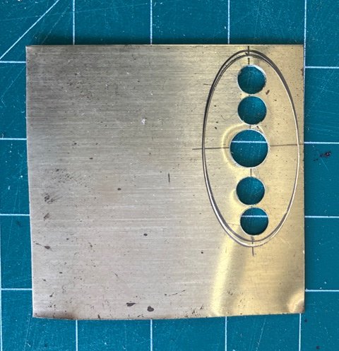
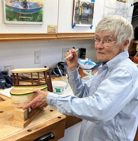
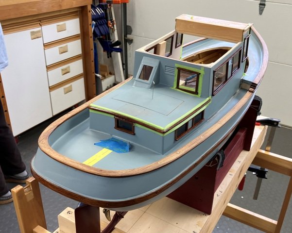
To wind up this month's posting, I continued to build out the interior of the pilothouse while Vicky leant her talented and steady hands to some detail varnishing. A brass bezel was made for the engine instruments Vicky also detailed the varnishing of various topsides bits of mahogany. And as you can see in this photo to the left, controls and instruments are being placed. A cove between the house and the level of the deck is curing. Hopefully, unlike the first attempt, this cove will only glue to the house and not the deck. So step up and take a look. That will do for now. Thank you for following along. Craig

-
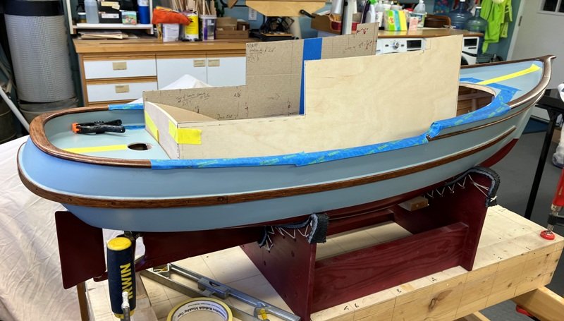
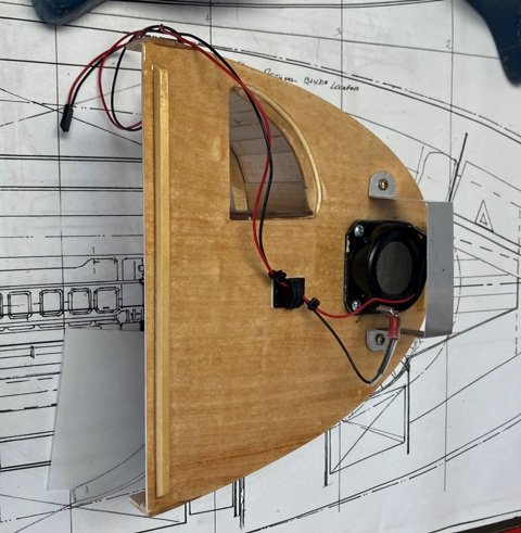
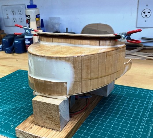
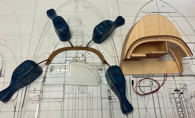
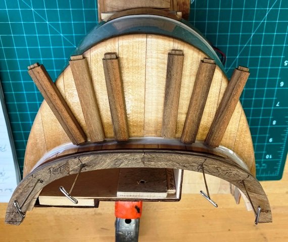
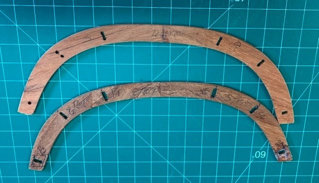
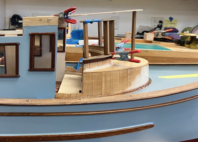
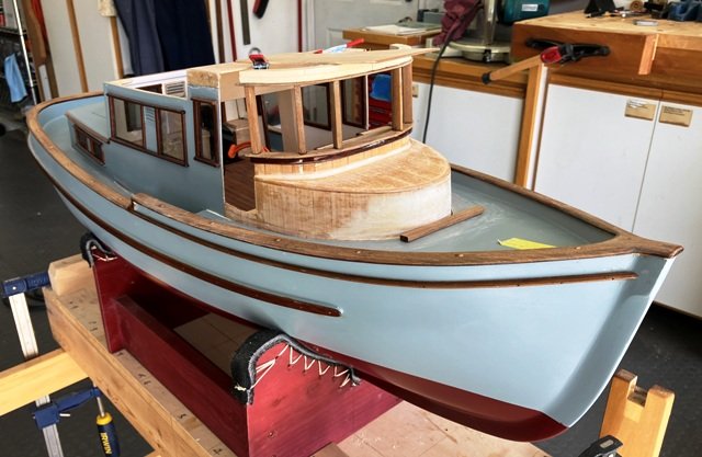
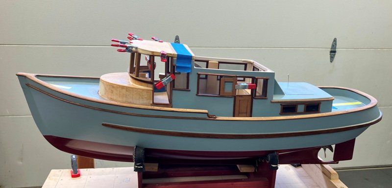
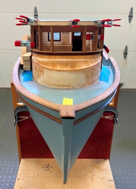
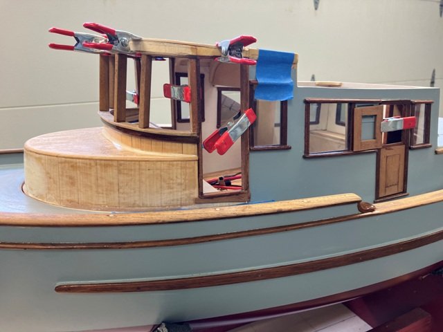
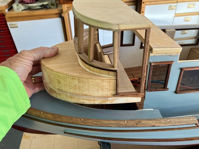
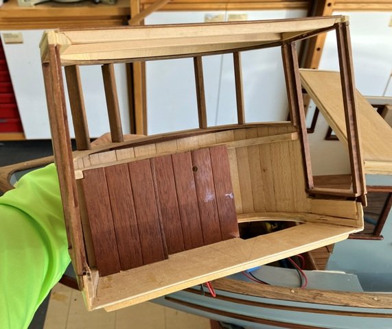
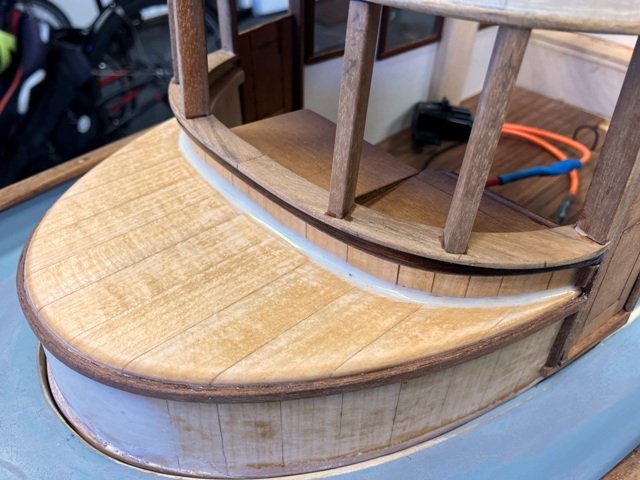
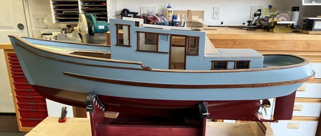
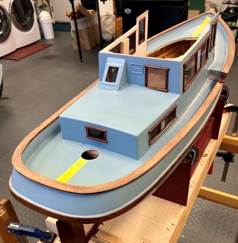
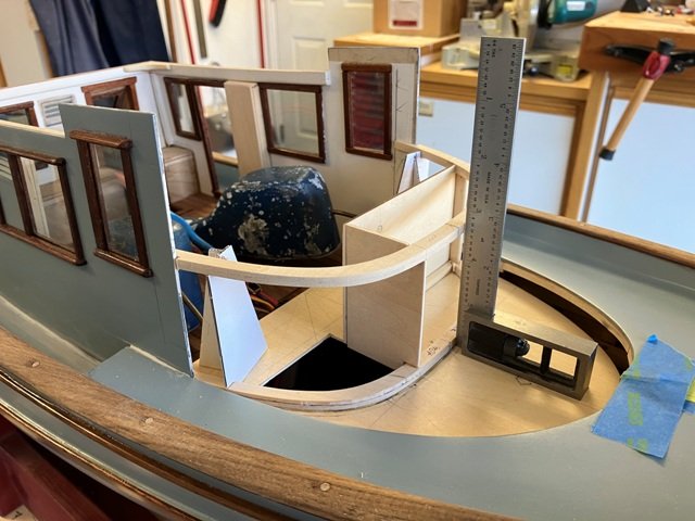
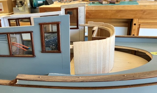
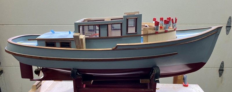
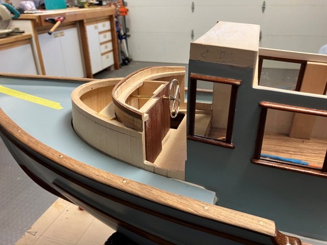
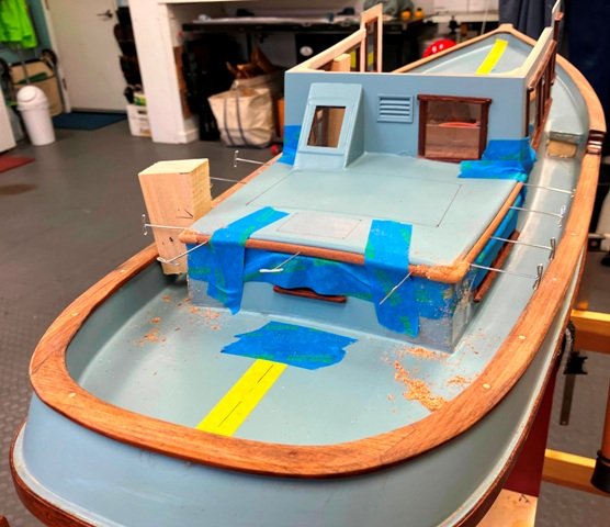
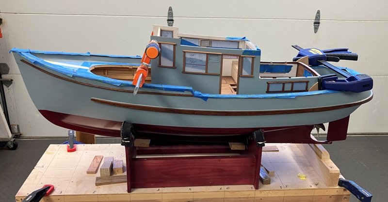
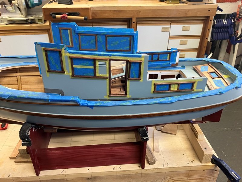
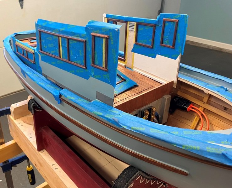
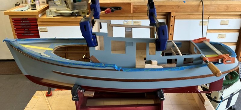
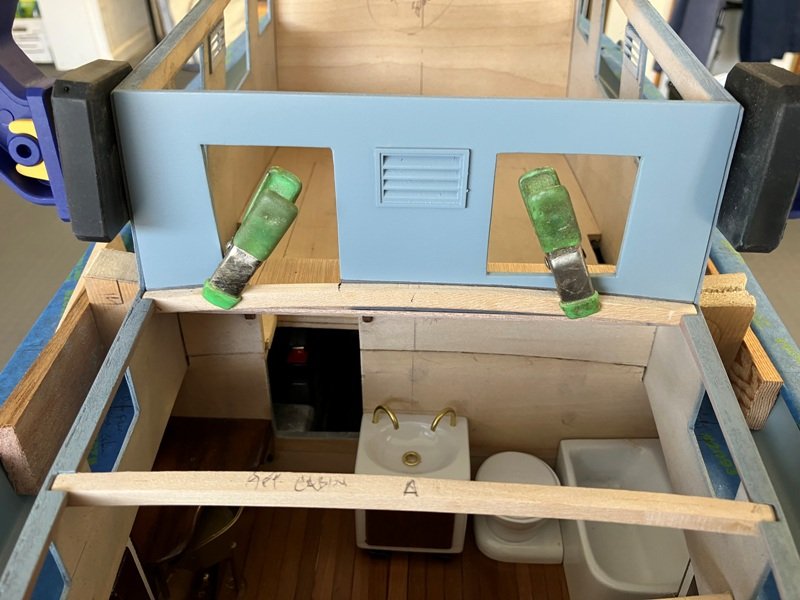
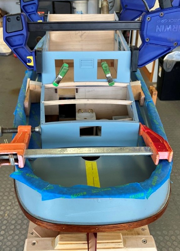
April 2, 2025 update: Prior to permanently closing over the raised portion of the house above the forepeak, I made provision for the speaker which is used to fool you into thinking this wee craft has a Gardner diesel in it. A hole was drilled from below for the body of the speaker and a guard bent up to protect the projecting lower portion of the speaker whenever the PH module is removed from the deck. The cabin top was then planked over with basswood, faired and sealed with 'glass/epoxy. The next task on my list was to begin the construction of the window framing for the pilot house. Upper and lower plates (head and sill?) were laid out and shaped to lay above the curved vertical face of the pilot house. The upright window jambs were fashion from some teak and made with tenons top and bottom. Corresponding mortices were cut into the plates. This somewhat wobbly construct was then braced up and glued together. When set atop it's future location, I realized an oversight on my part: the window framework tilted aft a bit rather than presenting a vertical face to the elements. For most of it, the tilt was not a problem but the after jambs had to ultimately be cut free of their tenons and re-aligned to vertical to deal with the doors. A yellow cedar header was laminated up and glued to the head plate, beveled to follow the curve of the overhead plywood from the main cabin. The door framing was gotten out of some of that lovely Cuban mahogany and they were glued into place, reinforcing the re-positioned after window jambs port and starboard. As mentioned earlier, the whole pilothouse module is removable by lifting it out vertically. And the next photo gives an idea of basic area of the interior of the pilothouse. The final picture before I break this post up into two sections to keep it manageable shows the forward curved faces of the PH with a laminated moulding curving around the forward portion. Then we will visit the interior of the house. More to follow...
-
Oh, well...Can't have a CG fellow arrest the model for the color of the light board backs...back to flat black - whenever I get to them . Craig 😉
- 732 replies
-
- 1
-
-
- Lula
- sternwheeler
- (and 1 more)
-
Well, one learns something everyday...I have sailed with many black and natural finished light boards, but not white. Perhaps they were finished thus to avoid excessive glare from light scatter when on deck. (I note that it doesn't seem to help in fog or rain.) This use of white light boards, however, does make some sense and so I shall follow your logic with the light boards on TWILIGHT when I get to mounting them. Thanks again for the thorough research on all aspects of your model(s). Craig
- 732 replies
-
- 2
-
-
-
- Lula
- sternwheeler
- (and 1 more)
-
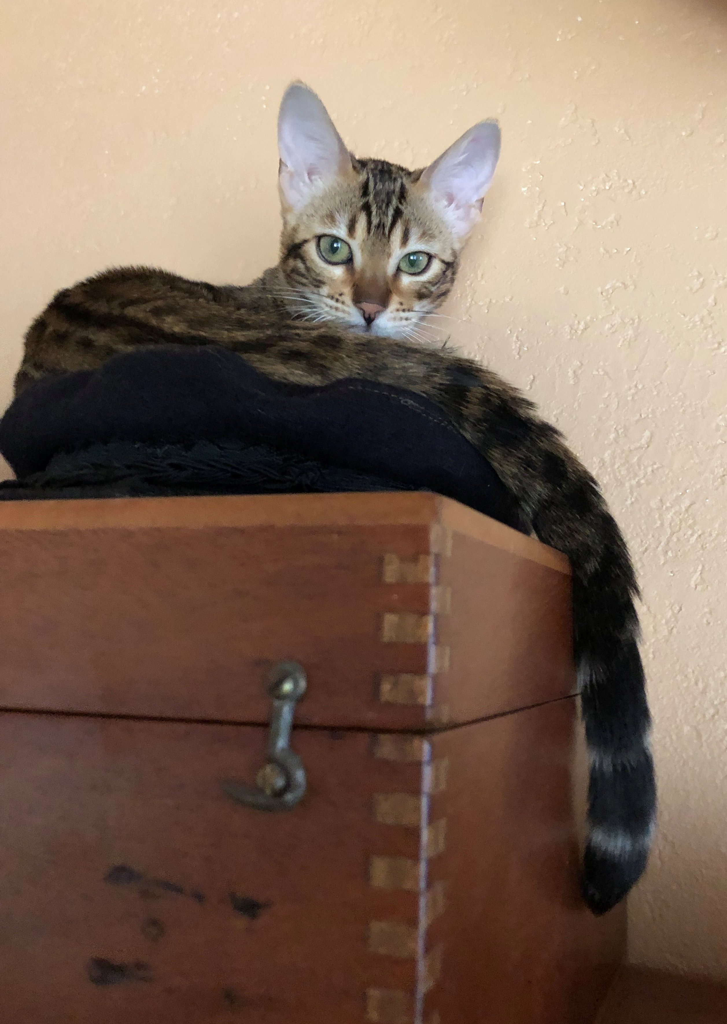
We also found that heading "uphill" (north) from California or Baja was very rarely an easy passage. We resorted to following the clipper route well offshore to get to Washington or British Columbia when sailing to minimize those tough slogs you mention. Fortunately, we are now "anchor down" and when the storms come arcing in from the Pacific bringing strong winds and tumultuous seas, we are grateful to tuck into the library, by the fireplace while Ballou, the cat, sleeps atop my sextant case.

-
Thank you for the compliment. There is definitely a recognizable "style" to the boats developed through hard-won experiences which must be capable of handling the often not-Pacific conditions. Since we had planned to use this craft for our liveaboard Pacific NW cruising home, the style seemed to make sense to me as her designer and it's also fun to develop for me, the (model) builder.
-
Simply magnificent!!
-
My guess is that it should - especially at your scale of work - and this was my first intro to an actual piece of the wood. As a boat designer and builder over the years, I had read of it and wondered what made it so highly esteemed. Very special timber.
-
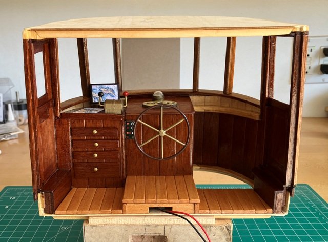
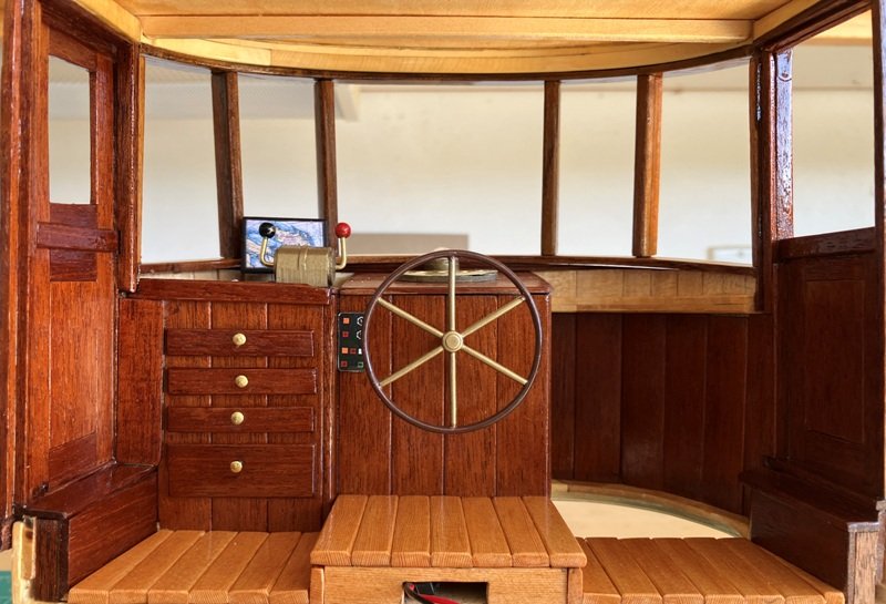
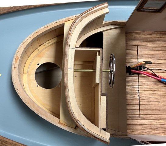
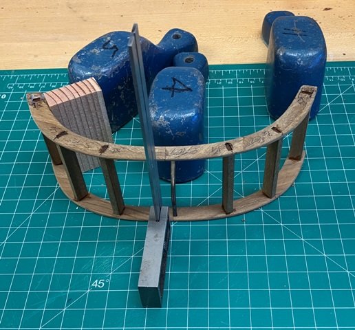
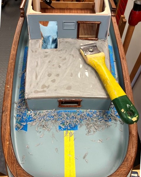
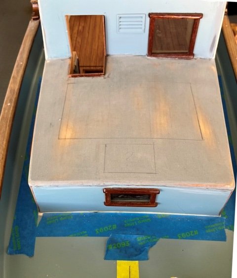
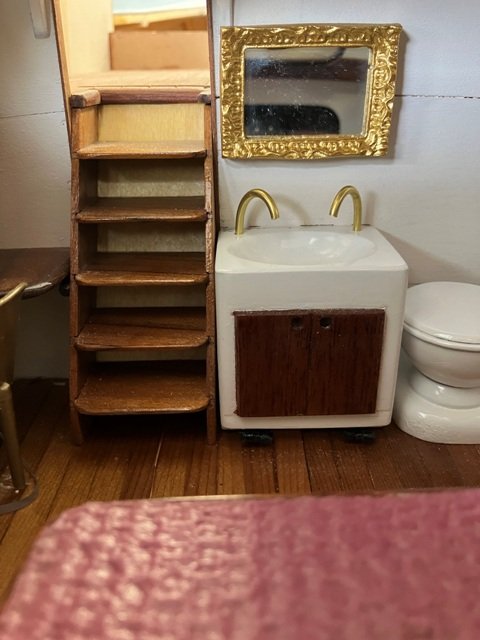
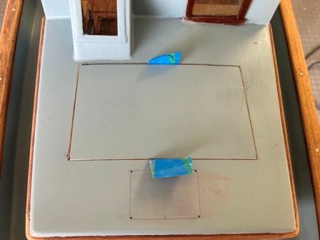
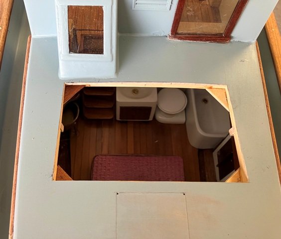
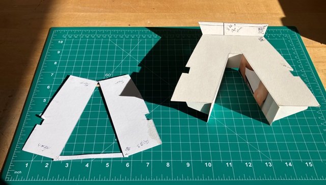
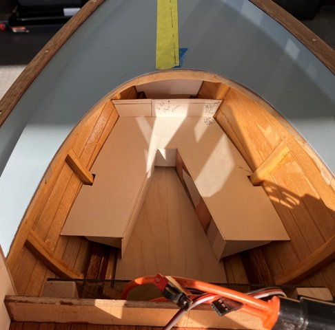
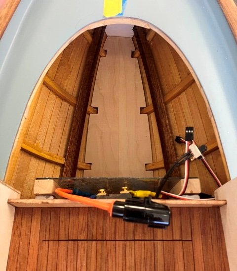
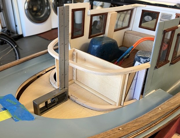
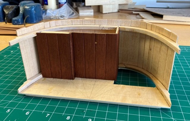
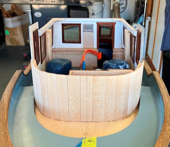
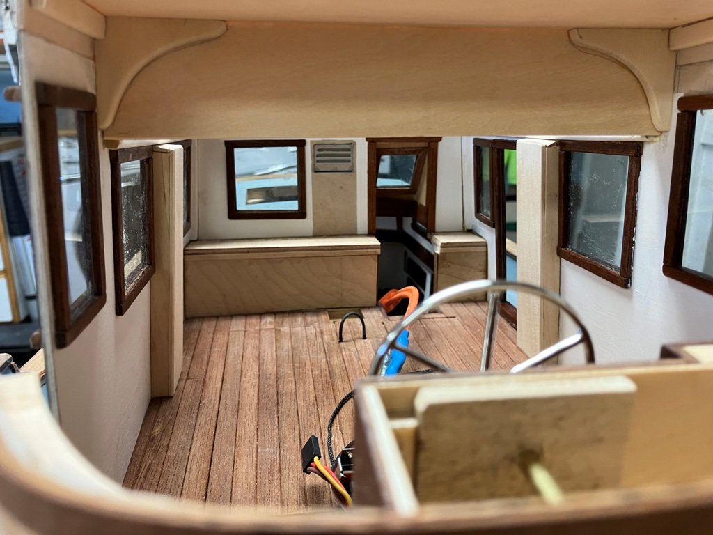
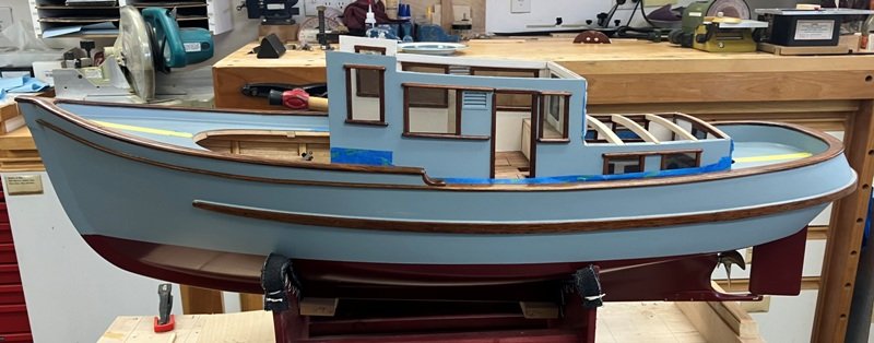
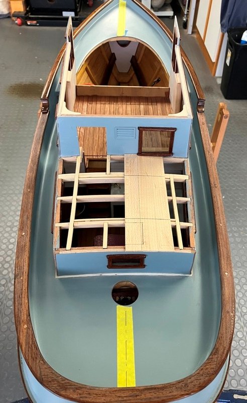
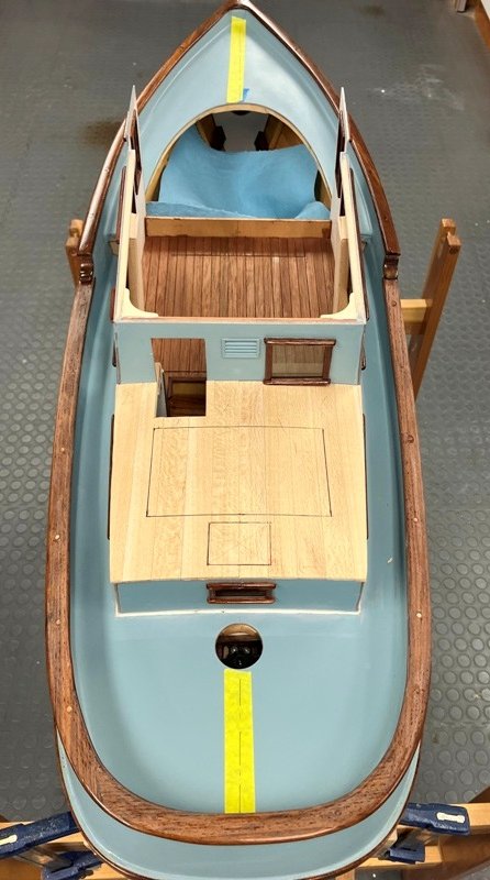
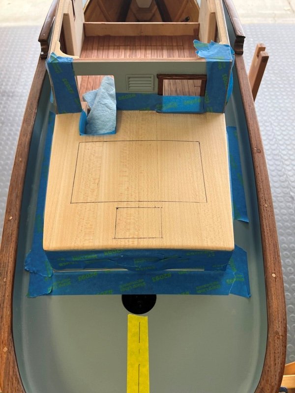
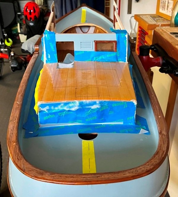
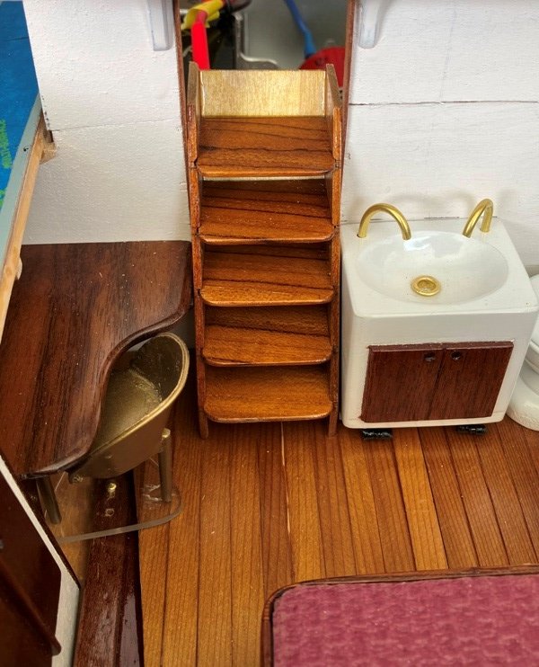
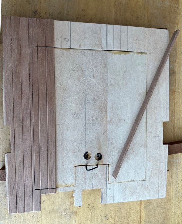
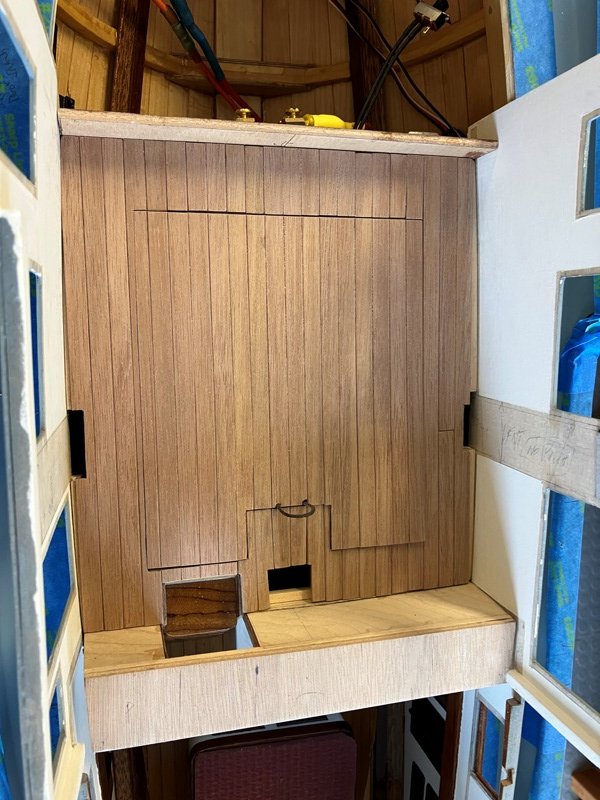
March 6, 2025 Update During the weeks of February, the cabin top of the stern cabin was completed. The "flow coat" of epoxy and sanding filler was applied, scraped down and then block-sanded. The cover over the steps down into the stern cabin was fabricated, scribed to the curving cabin top, checked for proper angles and bonded in place. The cabin top was then primed and painted. The hatch was cut in the cabin top. Corner supports for the hatch were glued to the undersides of the beams and carlins. A mahogany molding was fitted just below the transition from the cabin sides to the aft cabin top And if you were laying down in the bunk when you took a photo looking forward, here is the current view with the hatch open: Moving to the bow area, I decided to modify the fore cabin's original arrangement due to possible access requirements to the R/C wiring at the bus bar. A cabin sole was mocked up with card and then cut from 1/16" birch plywood. Then, card berth-shaped panels were cut out and temporarily tabbed together (after a fair amount of fiddling). A more thorough card joinery exploration followed and I feel that when the time is right, this will serve satisfactorily for patterning the actual birch ply construction of the V-berth area. So, (finally!) work commenced on the actual pilot house unit. R/C access drove the decision to build this as a vertically removable unit and a horizontal sole was cut out as the base on which to erect the structure. The forward face of the pilot house has a curved, upright shape, so I laminated a pair of "plates" to support the 1/8" th. vertical basswood staves which would form the face of the curve. While the lower plate simply glued down in place onto the ply sole, the upper plate needed support while the staving was glued on. Some of this support was derived from the lower cabinetry for the navigation station /steering wheel structure while the after edges of the upper "plate"(carlin?) were supported on a pair of temporary card pylons. The quarter-circle hole will provide the entry down a curving set of steps (not yet built) into the fore cabin. The faces of the pilot house joinery were paneled with 1/16" Cuban mahogany, a chunk of which was kindly gifted to me during my visit last summer with Roger Pellet. It apparently came from an antique bit of furniture which Roger collected many years ago and it has a lovely grain and color. My thanks to Roger! At the forward end of the pilot house structure is a lower portion of the house for deck access, ventilation and light to the fore cabin below. The curving face of this extension was built up with staving similar to the main portion of the pilot house and the sides fair back into the line of the pilot house sides just forward of the location for the (future) pilot house doors P&S. Along about this time, while making up a card template for these PH doors, I noticed an error by the designer: The doors, as drawn would have been all of 5'-6" tall. (I had a few choices thoughts for the designer's ineptitude) . So the boatbuilder conferred with the designer and *we* agreed to a solution: Raise the height of the pilot house sufficiently to provide for 6'-3" (scale) doors. While this modification was ongoing, hanging knees of AYC were glued in place to support the 1/16" ply extensions as well as the the sub-ceiling above. The vertical panel at the upper aft end of the pilot house was glued in to tie the raised cabin sides together with the correct rake. (The designer slunk off, mumbling about, "nobody is perfect! ...Sniff...) Onward. Rummaging through my parts bin, I located the ship's steering wheel and temporarily mounted it in place to check for sufficient clearances from the joinery. To finish up this post today, here is an image from just forward of the future pilot house windows, looking aft into the as-yet un-built main cabin. Apologies about the various wires photo-bombing the picture. Thanks for looking in. I do appreciate your support and comments. Until again, Craig
-
Given how small they are relative to the hull and the probable cruising speed of the yacht, I imagine that they were probably not particularly successful in attenuating the roll. However, knowing that they had been installed (expensively, no doubt), perhaps the owner(s) just "felt" better.
-
Yes, I think that we shall have to place a crew member in the pilot house and another in the galley...and a cat somewhere in the way.
-
Thank you, Keith, Gary and Roger for your compliments/support. I appreciate your visits to the tale. We are proceeding in the "boatshop" a little more each day. Craig
-
Yes, John. that is the plan - and the primary reason for that cabin top "hatch" - though based on past boat experiences, whether full scale or a model, it's also never a good idea to totally block access to any space. It may take someone's smaller hands....
-
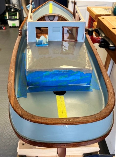
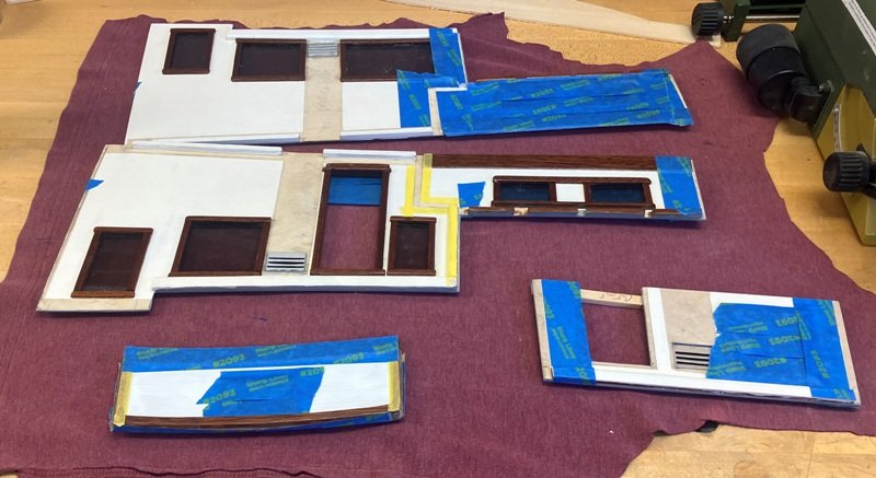
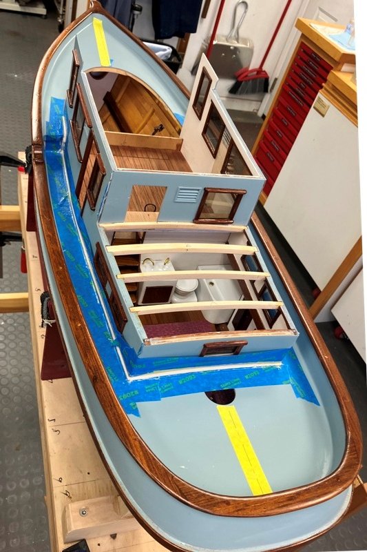
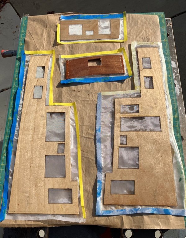
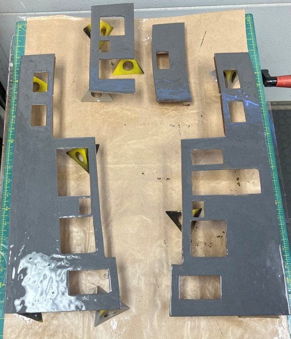
February 5, 2025 In preparation for finally gluing the pieces of the main cabin together and onto the hull, I decided to frame out and fit the various windows. Initially, I felt that only the exterior portion of the frames could be done at this stage due to the requirement to be able to slip the main cabin sole down tightly into place during the actual glue-up. However, with a bit of care in the sequencing of the positioning of the cabin sides and the sole, I realized that the window framing could be completed beforehand. This also permitted, with appropriate masking, the painting and varnishing which would have been far more difficult post glue-up. The windows were traced from the actual openings and cut from a sheet of 1/16" thick polycarbonate. The window framings were made from meranti and were varnished after being glued in place. The individual cabin sides and partial bulkheads were repeatedly dry-fitted and then removed to accommodate these steps. Masking and unmasking and re-masking seemed to be norm for a couple of weeks. The day arrived (finally) when the check-list indicated it was time to mix and apply the epoxy. Fortunately, all the practice of setting up (and removing) the parts of the cabin helped to minimize anxiety from the presence of wet, sticky glue. When the clamps and masking tapes were cleared away, this portion of the structure was delightfully stiff and the process of creating a cove at the intersection of the house and the deck could proceed. The aft cabin's roof was next on my list. I framed it to be able to provide a removable panel in the overhead for possible future access. The 1/8" thick basswood planks were glued to the beams and carlins and carefully marked for the locations of the future access cut-outs. While I was at it, I also fitted a pair of AYC lodging knees to upper aft corners of the main cabin. The aft cabin top was sanded fair, re-scribed and re-marked for clarity. It was given a layer of F/G cloth set in 2 coats of epoxy and this will be followed with a coat of light fairing epoxy for pre-painting smoothing. While these cosmetic details finish up, I plan to begin focussing on the development of the pilot house portion of the cabin. Until then, my thanks for looking in and for any future suggestions. Craig
-
The nibbing-in of the planking on the foredeck looks very crisp and proper. Well done, Greg!
-
Thank you, John. Just trying to match the "standards" I see on this supportive site.
-
Thank you, Gary. I very much appreciate your kind words.
-
I am so impressed by the detail you manage at this tiny scale! What a delight to see! A friend and boatbuilder in Sidney, BC built some years ago a 2-deck live-aboard stern wheeler as a home for he and his lovely wife. The fully-functional pilot house enjoys lovely views and the side windows can be dropped down into slots to permit one to lean an arm on the sill while navigating along. I wonder if the pictured LULA might have enjoyed a similar feature - the forward window looks to have a possible handle(?). Since the master of your Lula will have to look around the stack....? 😉
- 732 replies
-
- 5
-
-
-
- Lula
- sternwheeler
- (and 1 more)
-
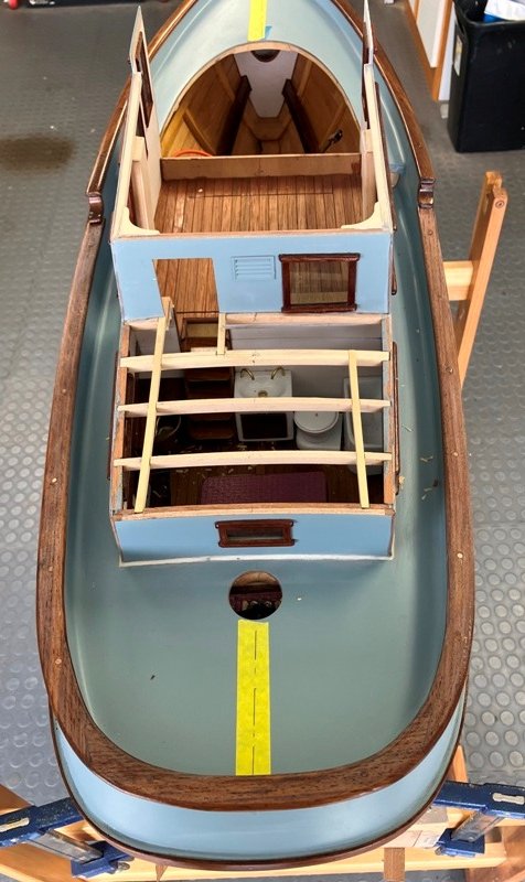
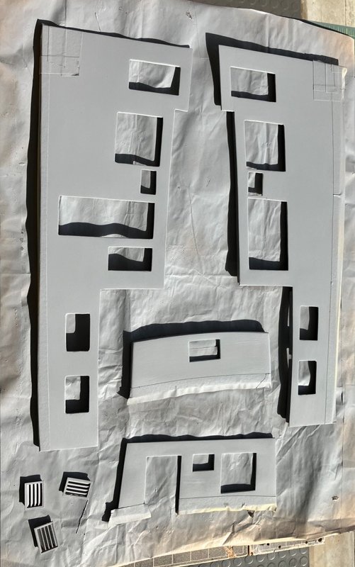
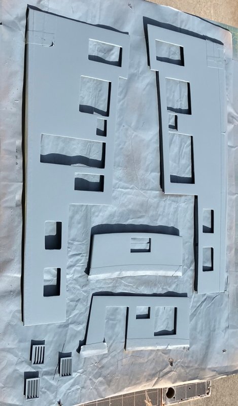
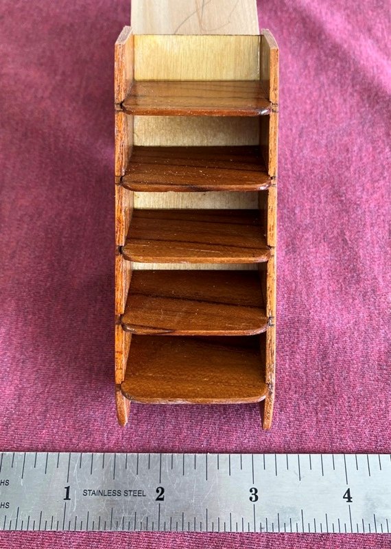
To continue the tale: The cabin panels were laid out and the exterior sides covered with light FG cloth set is epoxy as in other portions of this build. The weave of the cloth was then filled with another coat of clear, followed by the fairing coat which is an easy-leveling mix. Once the fairing coat is sanded smooth, a couple of coats of primer were sprayed on, sanded between and then finished with the color coats. Once again, the panels were dry-fitted in place. The stern cabin has a few items to fit which will be easier done before the cabin sides are permanently glued in place. One of these is the creation and fitting of the steps from the main cabin down to the aft cabin. These were built up from a nice plank of teak and a scrap of the 1/16" thick birch ply. The first beams for the aft cabin roof were fitted and then set aside until the cabin side glue-up time. The beam crossing above the location of the steps will be cut for the opening to permit the crew to go below without clonking their noggins. There will be an angled "trunk" cover from the aft side of the main cabin down to the top of aft cabin to keep the wet out. I will finish this update with a couple of photos of the planking of the cabin sole. The sole hatch is held in place with a pair of magnets. (not shown). Thanks to all for your support and sound advice. I greatly appreciate your comments and guidance. Until again, Craig
-
Thanks for the praise, Keith. I hope that I am able to "stay ahead of the curve" with the preplanning. I note that I cannot fit the inner window moldings to the main cabin until the sole is permanently in place because of the tight clearance and the camber of the sides.
-
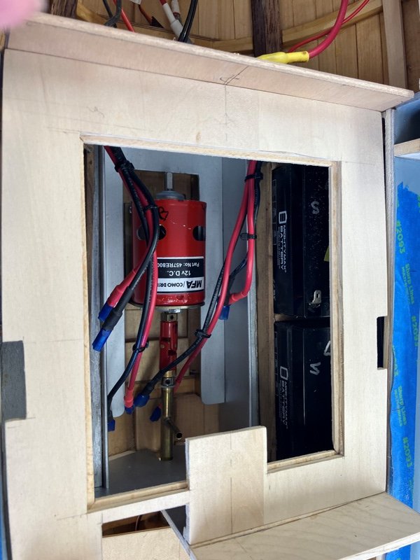
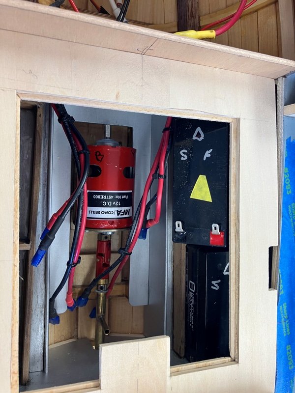
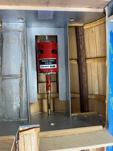
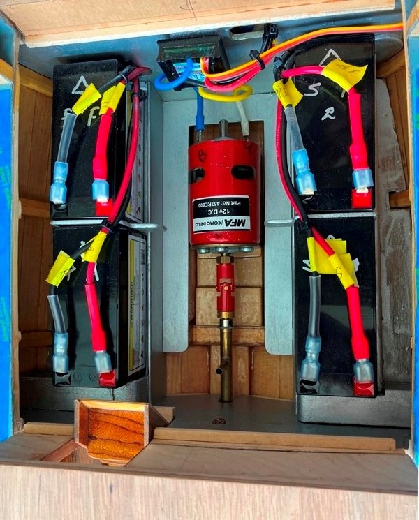
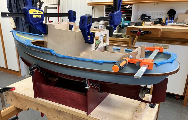
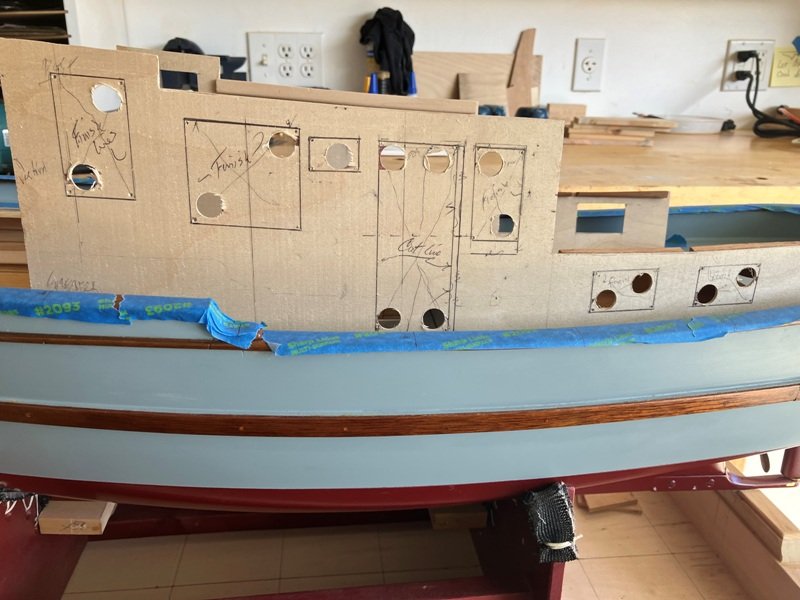
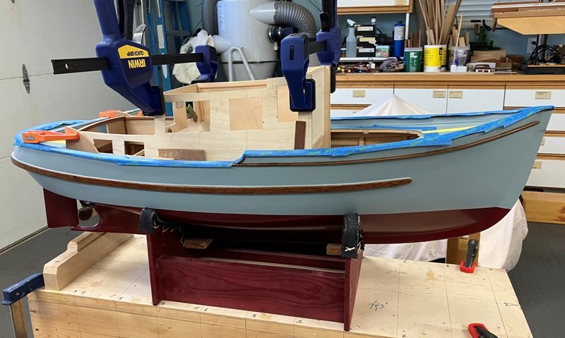
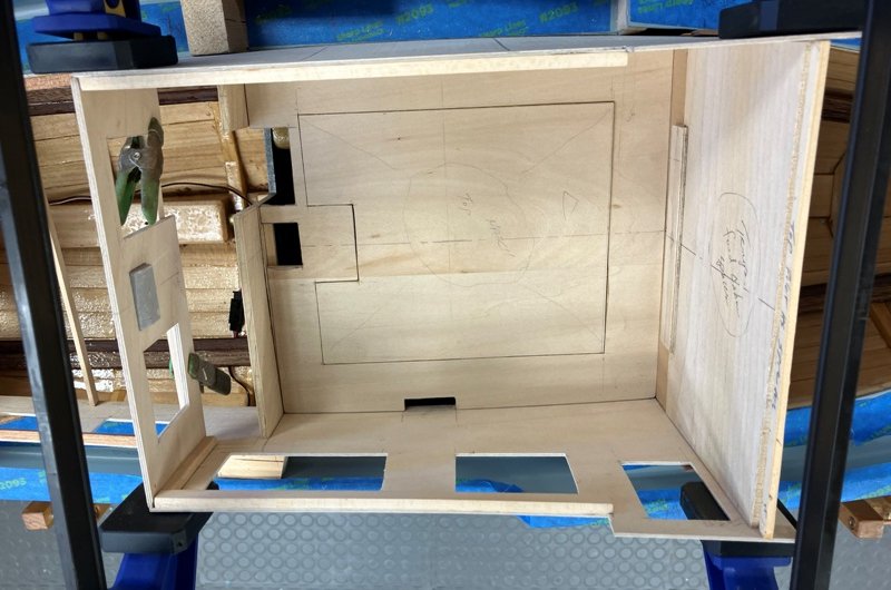
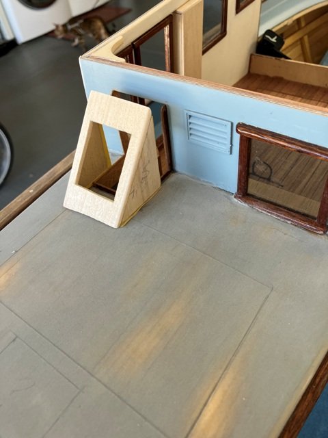
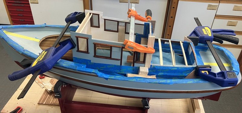
January 10th, 2025 update: It has been an interesting first year to be building this model and I am delighted to have the opportunity to continue the work into a second year. As noted back in November, I began by working on the construction of the cabin structures. I decided to continue working from aft to forward since I feel that the pilothouse area will be more demanding. Card panels were first mocked up to check fits before cutting the 1/16" baltic birch ply for the actual sides. the aft face of the cabin was gotten out of some 3/16" thick meranti ply. Another bulkhead was to be located at the aft end of the main cabin. The main cabin sole stretches forward to a step-up at the aft end of the pilot house and to hold the house sides out against the curved edge of the deck, this sole needed to be fitted prior to gluing the sides in place. It was fortunate that when dry-fitting the sole in place, I realized that the batteries below, as mounted, might become rather difficult to replace if needed. Trying to wrestle a battery out revealed the need to redo the battery mounts to bring the batteries closer to the centerline. After removing the batteries, I softened the epoxy with a heat gun and removed the previous set-up. A new arrangement was bonded in place and a more tidy wiring harness was developed. The construction of the house then resumed. The house sides camber inwards by 3 degrees to provide a bit more shoulder room when moving on the side decks and this design feature - easy to draw, not so easy to build - meant that the vertical bulkheads all had to incorporate the camber in the appropriate locations. This also necessitated ensuring that whatever structures which needed to span full width be at sole level in the cabin either were inserted prior to final glue-up of the cabin sides to the hull/deck or were to be pieced into place. In the above image, large-ish clamps are being used to pull the upper portion of the house sides inward to check fit and angles for the partial bulkheads. Once the cabin pieces could be dry-fitted together, window and door location measurements from the drawings were transferred to the sides. Holes were drilled to permit access by my fret saw and then the house was once again disassembled to accomplish the needed work. The main cabin subfloor was cut out from some light 1/4" thick ply, carefully fitted to provide a sturdy horizontal support to the hull at the deck level, and then an access hatch was cut in it to permit servicing the "motor/battery room". As a note, the temporary bulkhead spacer on the right side of the picture below helps keep the forward ends of these cabin side portions stable. I will break this update into portions to keep the size reasonable. Craig