
HOLIDAY DONATION DRIVE - SUPPORT MSW - DO YOUR PART TO KEEP THIS GREAT FORUM GOING! (Only 64 donations so far out of 49,000 members - C'mon guys!)
×


Egilman
-
Posts
4,377 -
Joined
-
Last visited
Content Type
Profiles
Forums
Gallery
Events
Everything posted by Egilman
-
 Don't we all?
 -
Masking fluid works well for doing hard edge camo, (as long as the base coat of paint adheres well) he's looking for that soft sprayed edge camo effect in the picture..... It's very doable with rattle can, (at least two different ways in my knowledge, probably more of them out there) but the technique is a bit more involved but not much different than his bluetack method. But you do have to see it done then it all falls into place..... Somebody will do one to illustrate the technique.... I'm sure of it...
-
It will come brother, with a little time it will come... Somebody around here will do a feathered edge camo job..... It's bound to happen...
-
That's the ticket. My doc, (a very fine younger lady btw, well, younger than me) suggested it after recieveing my firm NO when suggesting that they like to have that procedure ran at my age...... (and she suggested it with an understanding sweet smile) and it only has to be done once every couple of years instead of the annual probing of the other test.....
-
Thank you Ken, not quite finished fitting yet, before I put any grey paint on it I need to finish with the plastic cutting and gluing... Still have the center doghouse to make and mount the rudder pedals... before I paint it... I'll get up a shot when the conversion is all said an done before I fit it out with the PE...
-
That was sprayed directly by hand brother, no masks involved on the real thing.....
-
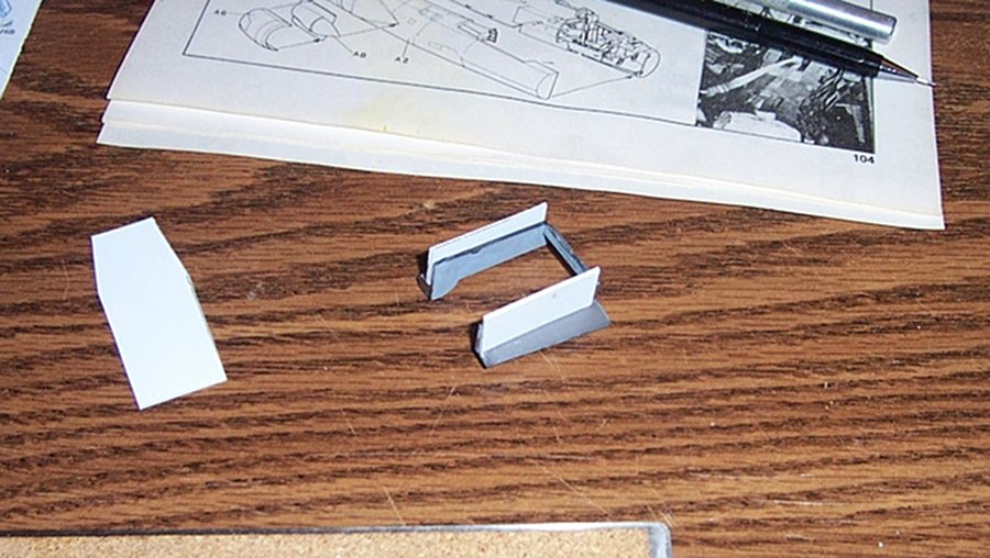
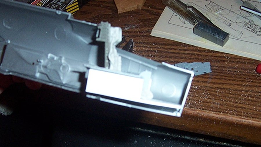
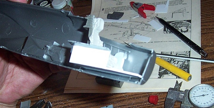
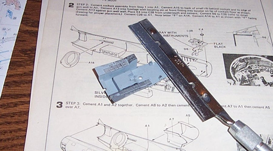
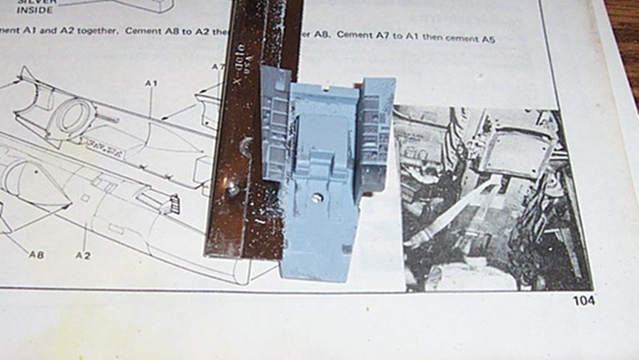
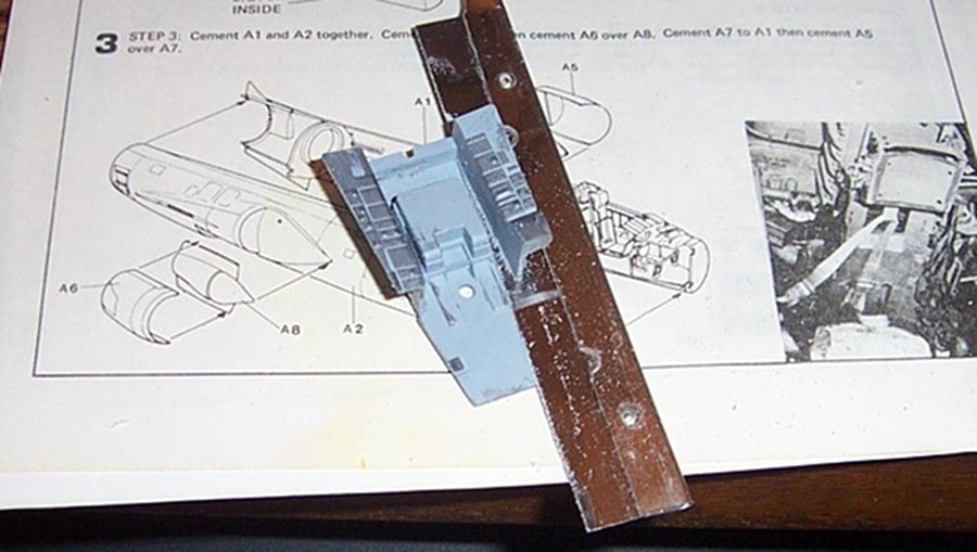
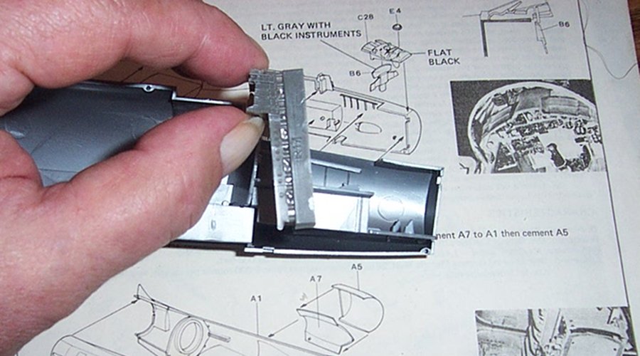
So we started the process of deepening the cockpit tub by cutting off the bottom..... Then we cut two pieces of plastic card to glue to the outsides of the side panels of the old cockpit.... Once glued, they are trimmed to length.... then using the old base as a pattern we cut another piece of plastic card to represent the new floor.... Rescaling is complete but we still need to fit it to the fuselage....... Now fitted into the fuselage all that is left is to check the ejection seat for proper fit in the new extended tub.... And finally the seat in proportion to the rebuilt cockpit tub... I still need to figure a way to locate and mount the rudder pedals, but the hard part is done.... Now to sand off the side panels and check the stick position in relation to the instrument panel and we are good to go.... Next up final fitting.... EG
-
You get used to them my friend, and, they are an absolutely necessary tool if your going to work with resin.....
-
Thank you very much Dennis, It's really appreciated!!!
-
B-25J Mitchell by Tom E - Revell - 1:48 Scale - PLASTIC
Egilman replied to Tom E's topic in Non-ship/categorised builds
My only suggestion is find something with a few rivets on it, then test it out and see what happens.... You will know when it is dry when it looks painted on... (best leave it overnight although it usually doesn't take that long) -
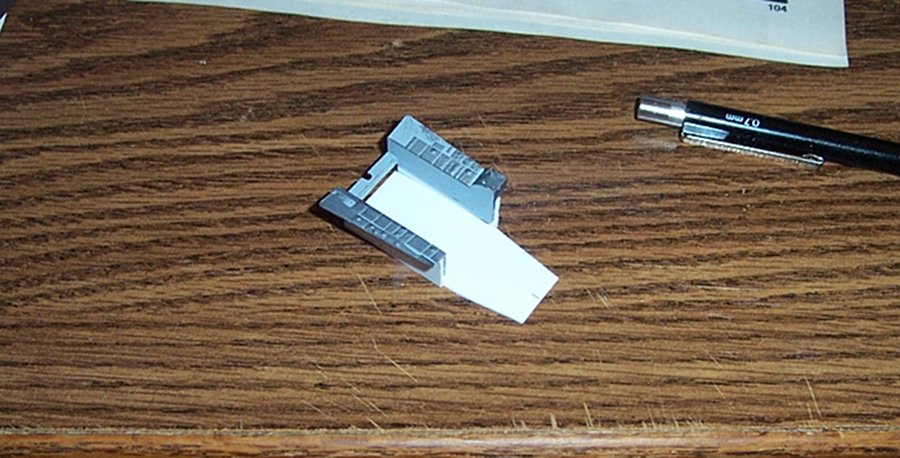
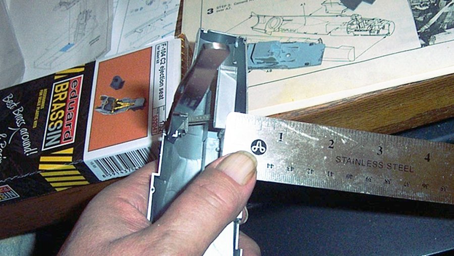
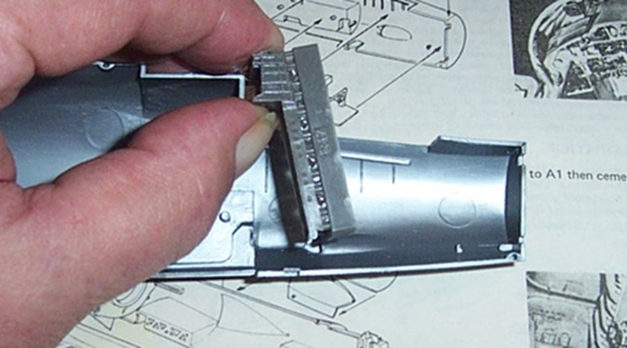
Ok, I've started hacking plastic..... Those two little nubbins got to go, they hold up the rudder pedals, not going to work with the PE..... Cutting the right side, I have to cut it along the floor cause I need to keep that slot on the back, it glues to the front wheel well to set it's location in the fuselage.... Cutting the left side..... Completely separated now... I should be able to get some measurements on how much I need to add to the sides... I know it's difficult to see but it measures a hair more than 1/8th of an inch. I think what I"m going to do is replace the floor with new rather than try and retain the old, this will give me a clean tub to work with and the seat was designed for a tub type cockpit.... the parts wall thickness is 46 thousandths so I will use 40 to make the sides, it will also allow me to create a crossbar support for the rudder pedals PE, then they will dangle like they are supposed to....
-
Give it time my friend, a course will soon reveal itself....
-
Cheer up brother, we've all been in the same boat....... You do beautiful work.... don't let anyone (especially yourself) tell you otherwise....
-
Ok another question? Why? What I would do is find a decent sized cardboard box that can be knocked down when not being used, use it to place your model on when painting therefore you do not have to touch it when painting and you only have to control the paint not both paint and model at the same time.... when done painting knock the box down flat and slip it into a closet.....
-
Oh don't get disheartened brother, I owned an airbrush once, used it once, then put it away. (eventually gave it away) I've been rattle canning ever since.... The thing with rattle can that is most important is distance from what your spraying, right between 10-12 inches..... closer and your concentrating the spray too much, farther and the paint is dissapating/drying before it lands... Also important is spraying past the object your painting, multiple light coats, if you have to wait between coats then wait, comes out better in the end...... one other thing is a steady stroke over the object while spraying not too fast, not too slow, it took me almost 10 years to get the hang of it ........ It's like anything else, the more you do it, the better you will get at it...... while I was learning, one model would have a great finish, another would look blobby in places, it comes with time.... Also, there was a time in my life where the only modeling space I had was the kitchen table.... everything had to be picked up and put away before dinner time or bedtime... Admirals orders...... An airbrush isn't holding you back my friend.... That first packard I built for the wife was built and sprayed on the kitchen table.... You have the talent brother, ease comes with more time and repetition.... I'm sure you know the old saying practice makes perfect, and trust me when I say we have all practiced a bunch to get where we are at..... And learning to rattlecan only was part of that practice....
-
The whole point of masking the way you were is to keep a clean demarkation between the different colors but create a fade over effect in scale between the colors. (it's called feather edging) Extremely hard to do with an airbrush alone..... It's only my opinion my friend, but it's too rough an edge, there wouldn't be that much wear and tear on the paint, especially in the areas where it's showing greatest... the edge between the colors would remain feathered but still very clear....
-
Oh I've had my share of what the government calls a cushion... I was just joshin.... Yeah, I could use four or five more....
-
Well, it does "act" like a cushion while the pilot is flyin, it's when he is in the air and ain't flyin that it functions in it's other role....
-
No Ken, it's one seat, the dark grey part is the vertical ejection rails in styrene. The brassin seat kit comes with a resin seat, resin cushions, (two options) and a styrene full rail piece then the photoetch.....
-
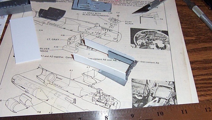
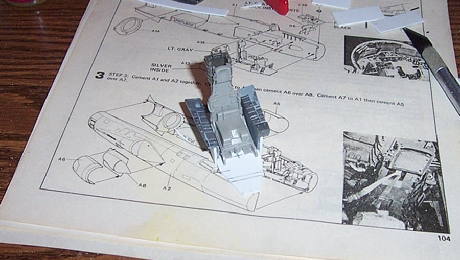
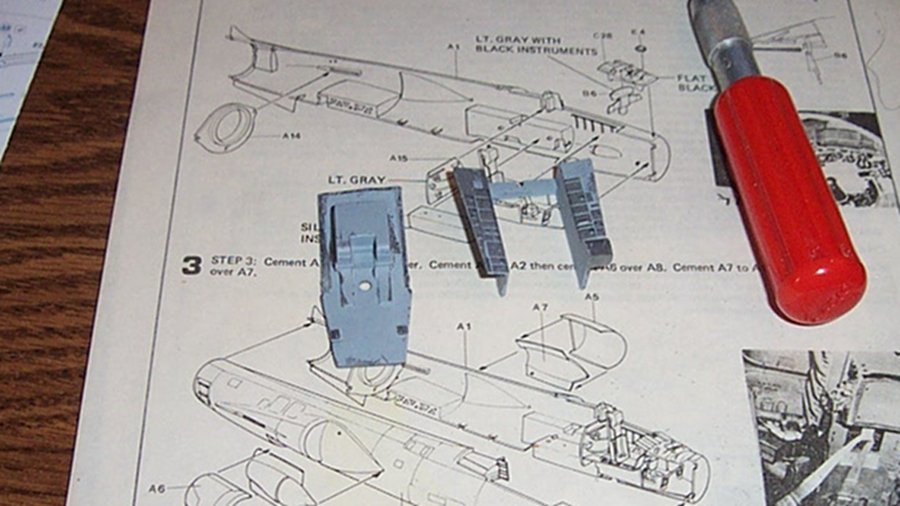
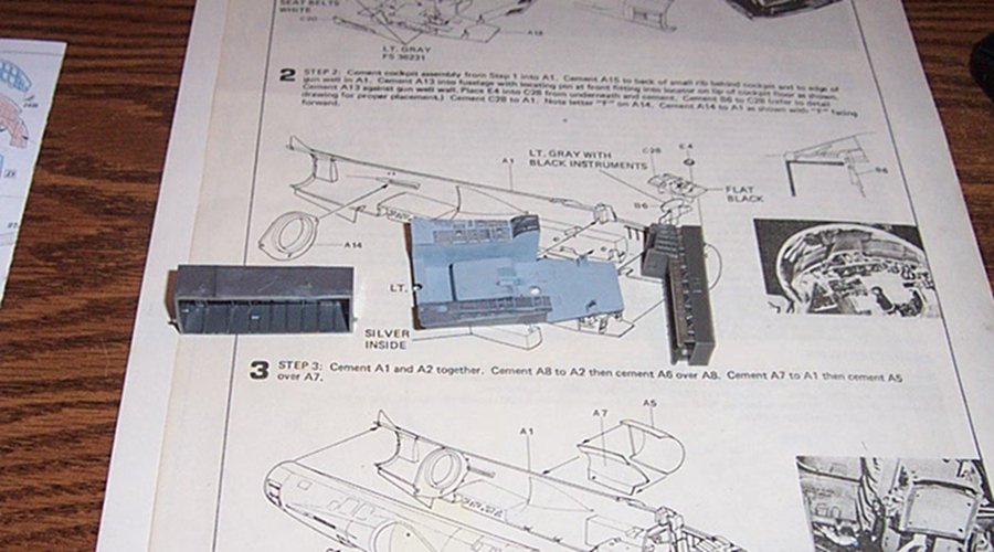
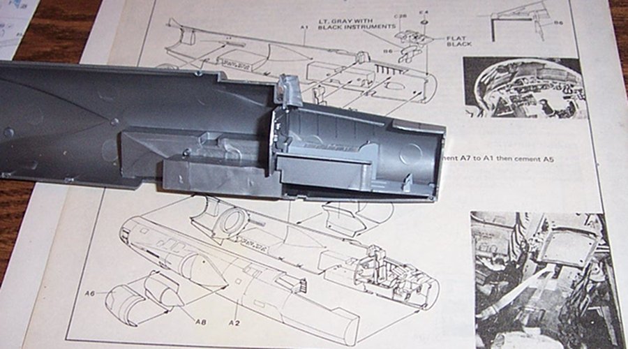
Ok, starting out on the cockpit... Right off the bat, we have three different sets of parts to correlate with each other representing three different models.... I have the Hasegawa base kit from the '70's and an Eduard resin set from the early 2000's and two Eduard photoetch sets from the late 2010's.... All represent a "C" model F-104.... The photoetch sets are designed for two different Italeri models.... Problem, I need to fit them all together into a presentable arrangement that looks sorta like the real thing..... These are the parts that make up the kit cockpit and the first part from the resin seat kit..... Adding the kits rear cockpit bulkhead and fitting them into the fuselage side shows where the cockpit sits in relation to the rest of the parts. and yes the nose wheelwell locates the cockpit.... (also note that the upper portion of the ejection seat rails is molded onto the fuselage sides easy to remove but that make the locator reference for the aftermarket parts) the rail section in the above photo has to sit in the same place as the molded on part.... The rail section positioned over the fuselage side lining up the upper support section to find out where the floor needs to be located... And the upper rail support structure looks to be in scale meaning that the rest of it is probably in scale also.... With this pic being taken at a slight angle the floor, wheelwell, (which locates fore and aft the cockpit floor) and the rear bulkhead in place, we line up the seat slide tracks and see where the end comes out.... It clearly appears to be longer than the kit parts so, the floor needs to be lowered. While the side panels remain at the current height in the cockpit... First step will be to cut off the cockpit floor and find out just how much we need to add to the sides to get the correct height for the ejection seat kit to fit.... Looks like Hasegawa took a little designers license back in the 70's when they created the kit.... (they did mold the seat cushion into the floor though probably to make the manufacturing process easier) I suppose back in the '70's this was considered acceptable and it was the only game in town, but today, it just doesn't cut it.... So I will be cutting it.... Next up fitting up a new, rerranged cockpit....
-
Moving quickly there denis.... The first act is over before I even get here.... I'm in, squeezing a seat in somewhere......
-
Yeah there's plenty pf photographic evidence of what those marking were... the two letters "DF" were the wing/squadron identification code the "A" was the specific aircraft... They are read from the front of the airplane to the back.... It wasn't the first B-17 to make 25 missions, it was the first to do it and return to the US.... (Suzy-Q was the first) Major Wyler probably had a lot to do with convincing the brass for it's return to do a bond tour.... Beautiful work dennis, I didn't know that the vertical stabilize paint patch was covering over a different marking, I thought it was a battle damage repair.. It's one of the things I love about doing research, you always learn something new and you never know where you'r going to learn it...
-
Thank you Ken. Historical research is another passion of mine, I like digging for the facts and reading about history also..... The next one I don't know about yet, but I have a feeling it's going to be a chopper of some type..... (I've got this zipper to finish and get the bandit rolling as well) I'm going to be busy for a while especially since the F-104 has taken a serious turn towards kitbashing and alterations which I hadn't planned for....
-
MRAP ATV by CDW - FINISHED - Rye Field - 1:35 Scale
Egilman replied to CDW's topic in Non-ship/categorised builds
ok three part mold. A shaft that is cut like threads except rounded like the inside of your spring. and an upper and lower half of the mold... The shaft moves in and out just like a rod would except it rotates at a certain pitch as it does, like it is threaded into the mold. So the two halves close, the side insert screws it's way into the mold, the plastic is pushed into the mold. When it has cooled a bit, the insert threads itself out and the mold halves separate.... The only Idea I can come up with... where and how the parts were located on the sprue would give some indication of how it was molded... -
MRAP ATV by CDW - FINISHED - Rye Field - 1:35 Scale
Egilman replied to CDW's topic in Non-ship/categorised builds
Yeah, that does pose an interesting problem.....
