HOLIDAY DONATION DRIVE - SUPPORT MSW - DO YOUR PART TO KEEP THIS GREAT FORUM GOING! (Only 13 donations so far - C'mon guys!)
×


HakeZou
-
Posts
325 -
Joined
-
Last visited
Content Type
Profiles
Forums
Gallery
Events
Everything posted by HakeZou
-
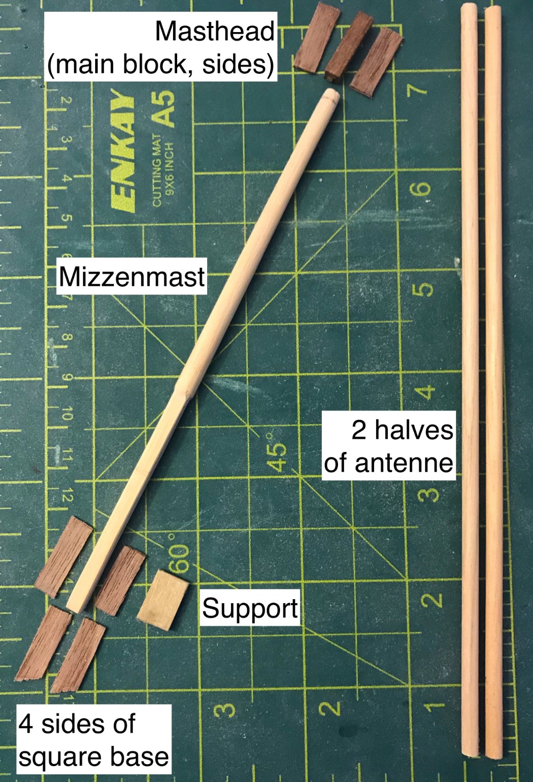
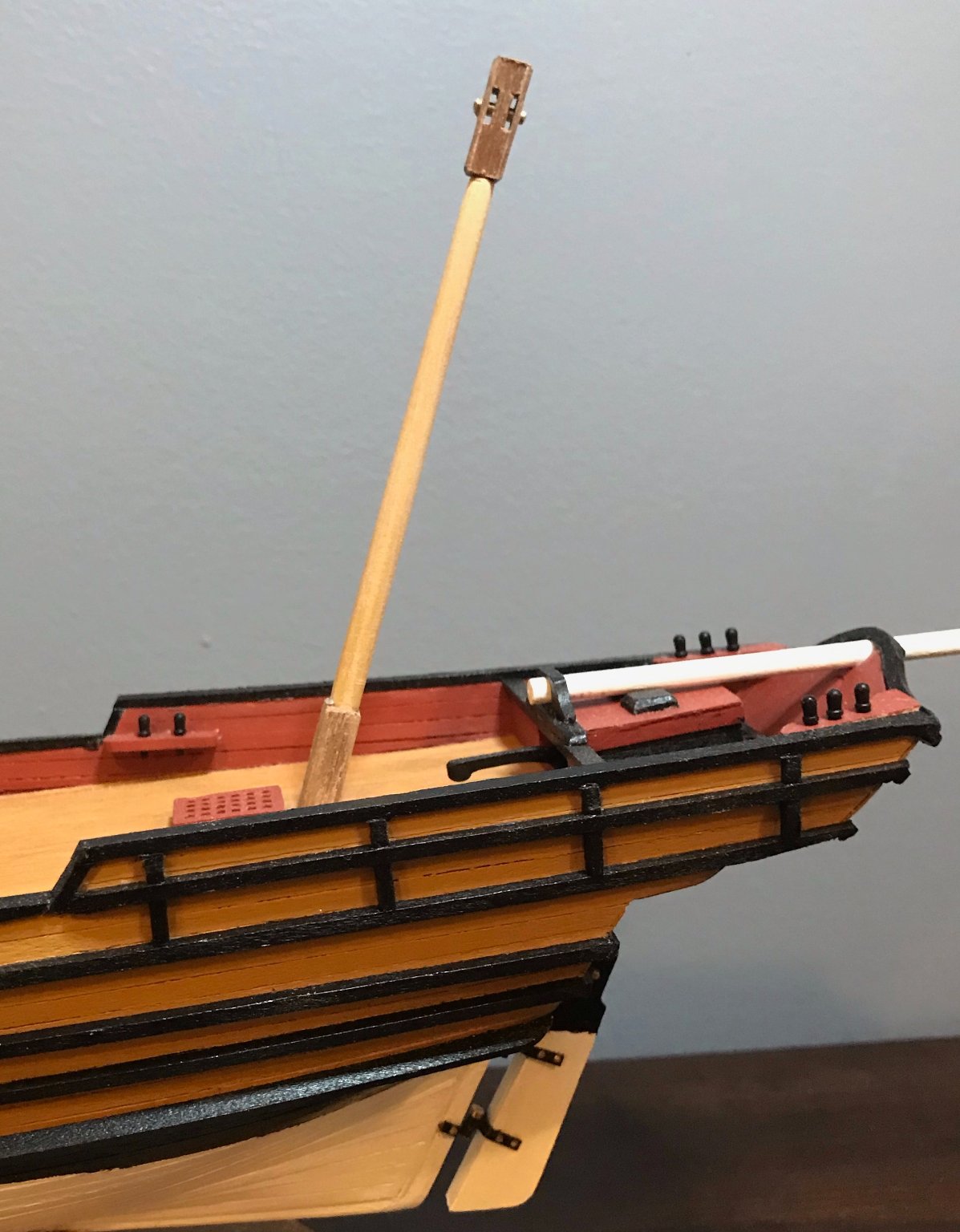
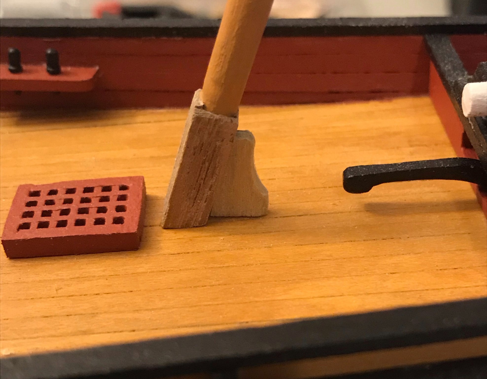
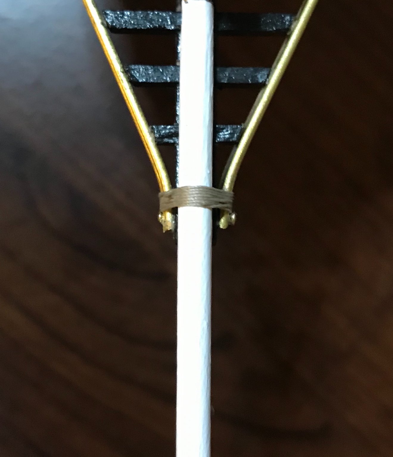
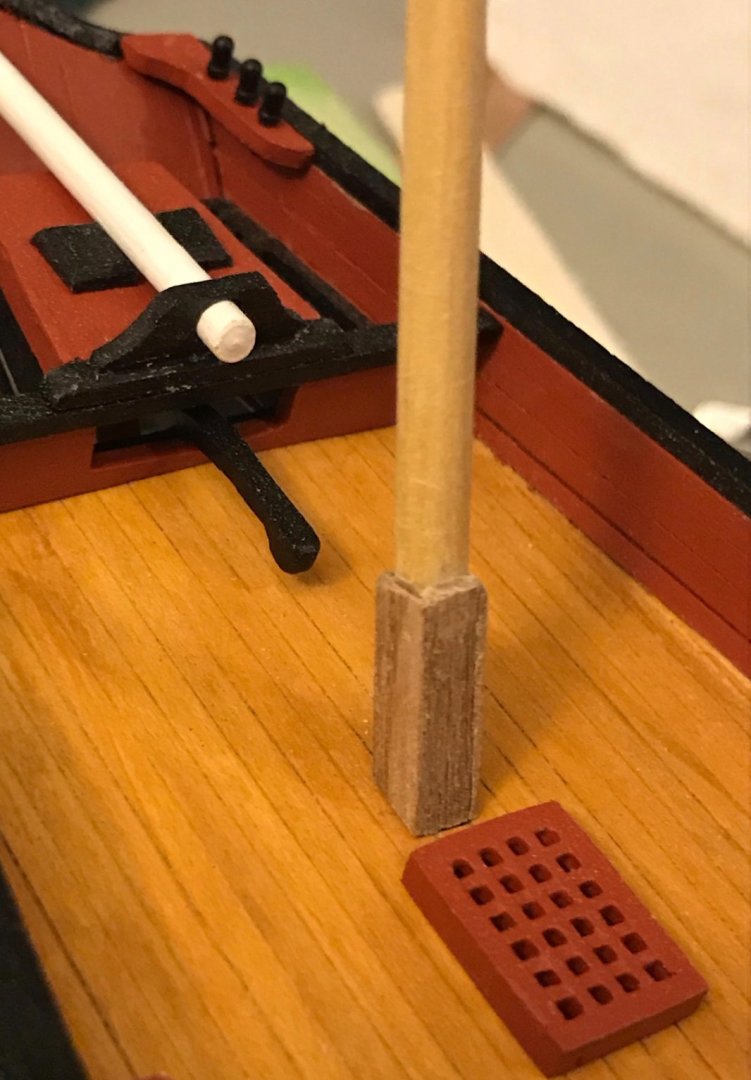
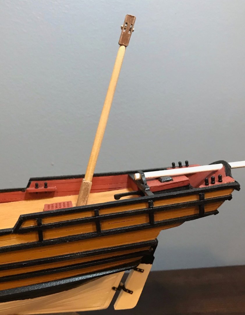
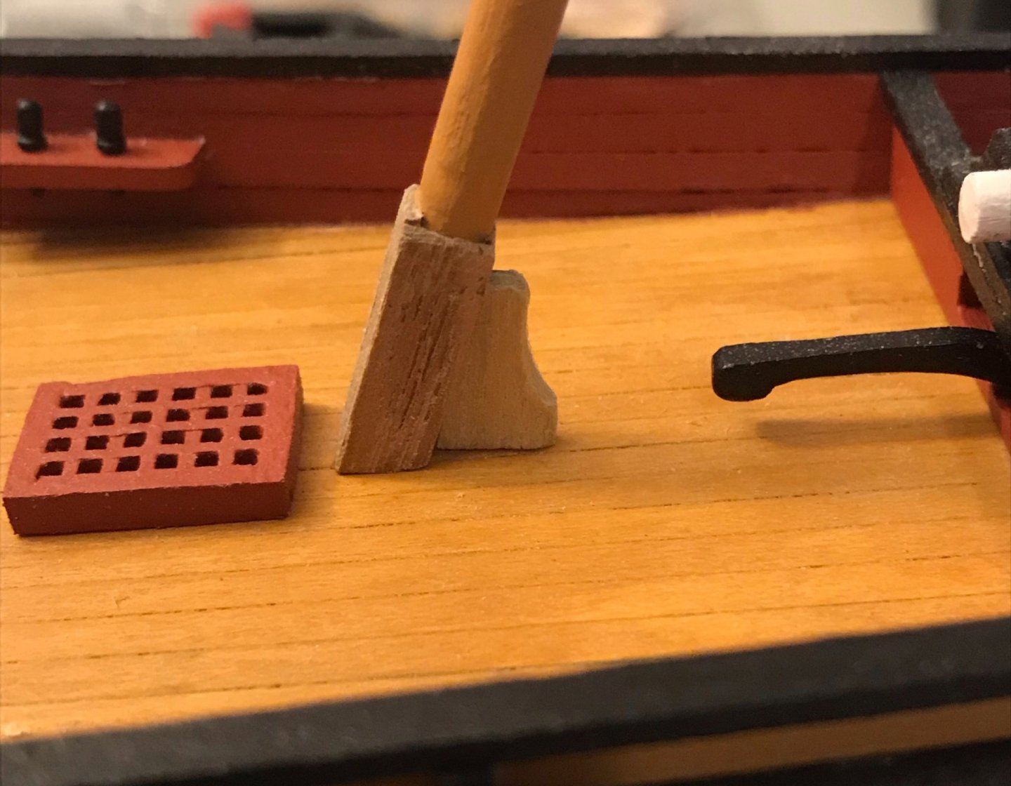
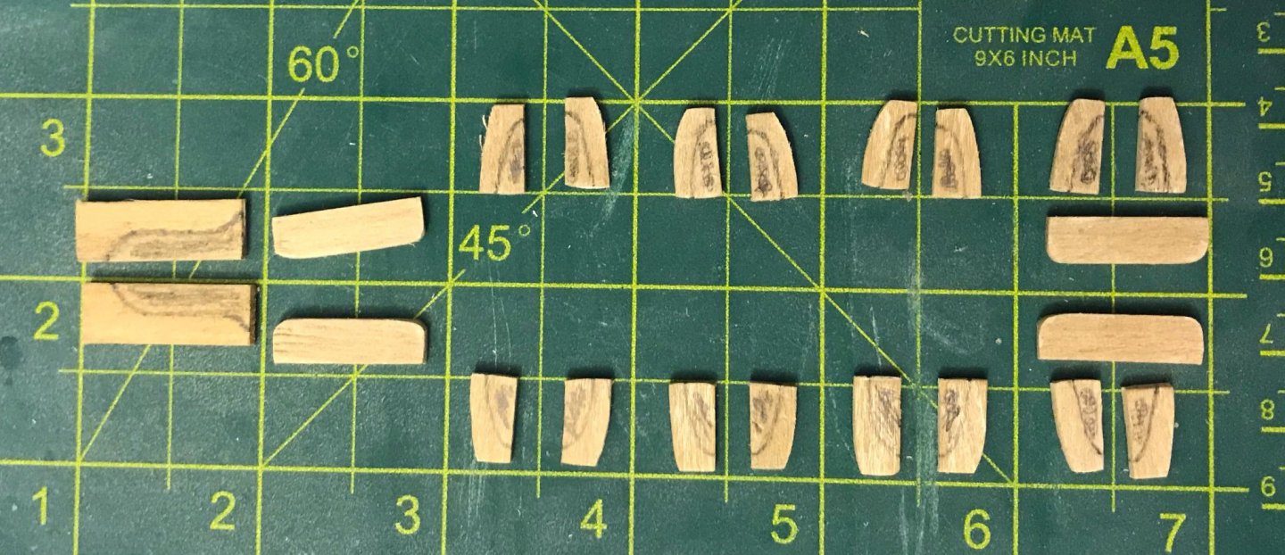
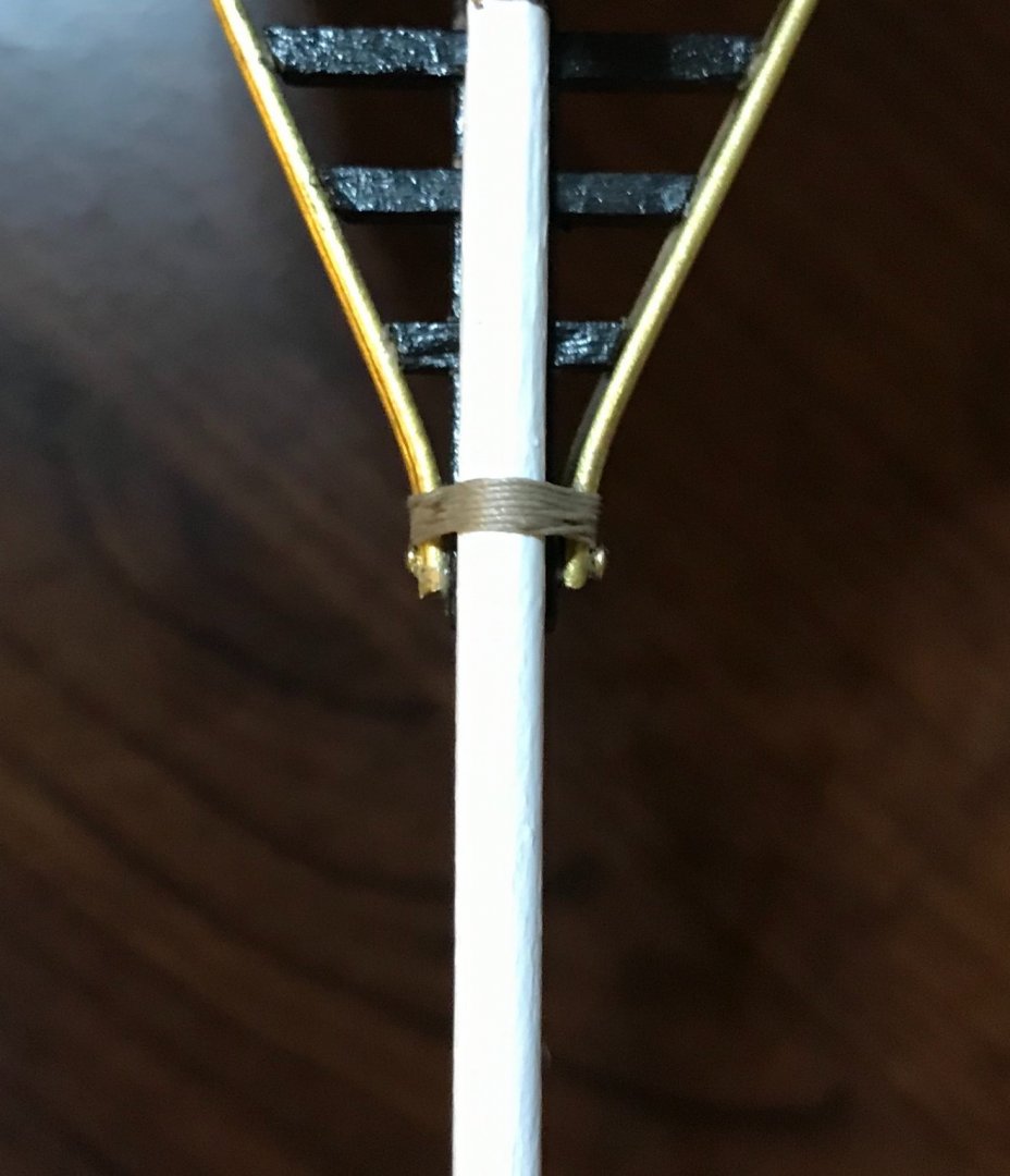
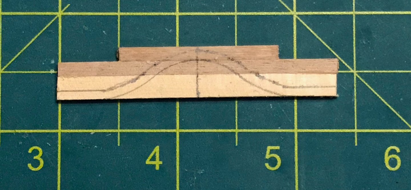
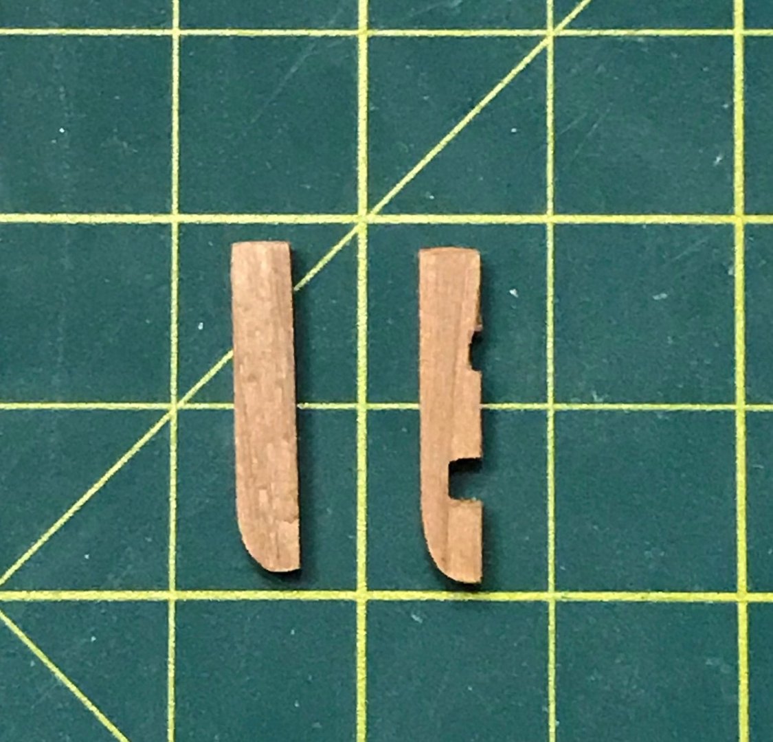
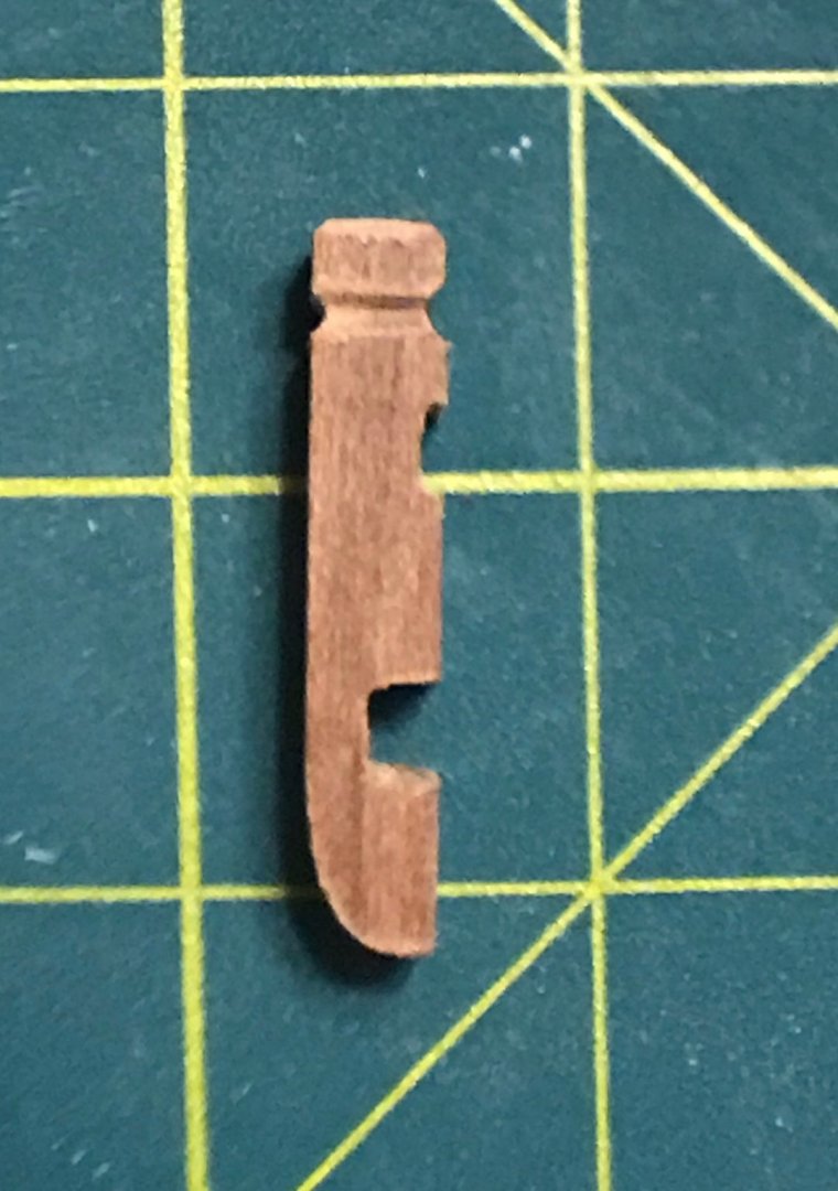
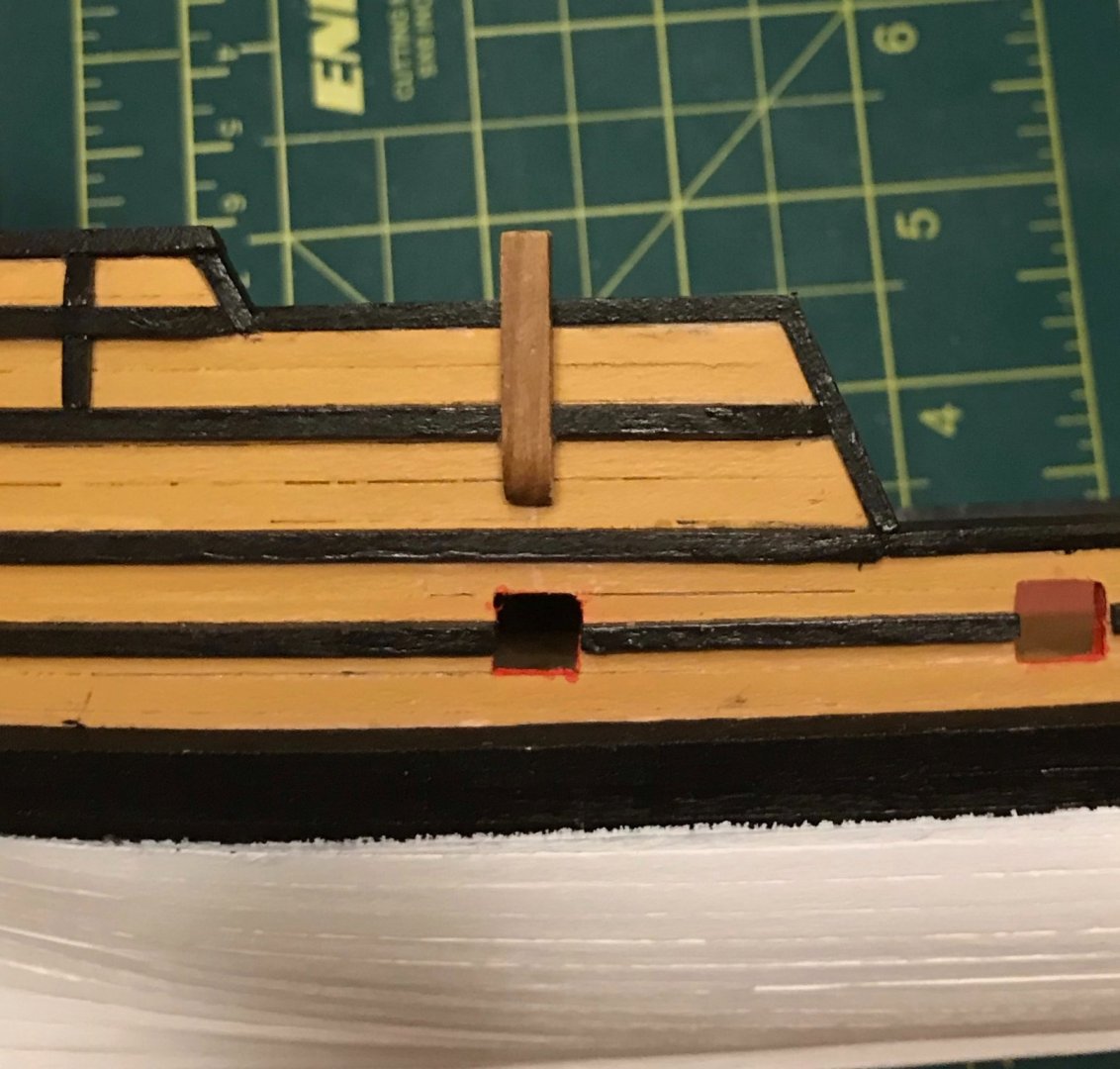
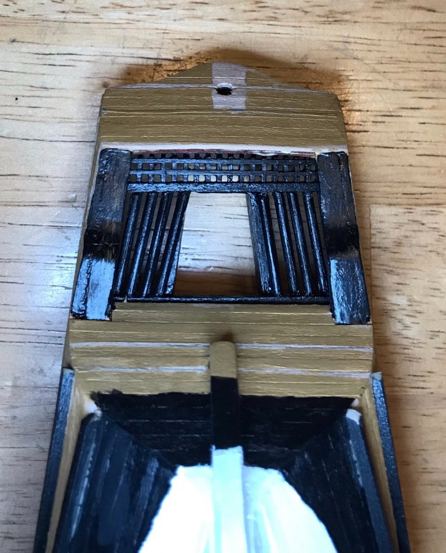
Thanks, Bob! I'm back to working on the deck fittings, starting with the easiest part, the aftdeck. Apart from two strips of eyebolts, the remaining work here is the mizzenmast. The first photo shows the various pieces. By the time I took the photo, I had already shaped the mast, so you'll note that the bottom portion is squared off and the top is tapered (from 5mm to 3mm, so it's a bit subtle). After attaching the pieces of the square base, I dry-fit the mast and did some sanding to make sure everything lined up well (first photo). Next up was the masthead, which was the most challenging step. After measuring and marking the slots, I drilled a hole through the main block. Then, I lined up one side piece against the main block and drilled through it, after which I did the same thing with the other side. I double-checked the alignment by running a piece of brass wire through all three holes. Thanks to the 2mm cushion on the width of the side pieces (main block is 4x4, side pieces are 1x6), I was satisfied with my first attempt. After cutting out the two slots from the main block, I glued on the side pieces and inserted the brass wire to ensure that everything was aligned. Finally, after sanding down the side pieces, I trimmed the brass wire and hammered down the ends to form rivet heads. (That last touch was inspired by watching Leo Goolden's "Tally Ho" videos. It took a lot of patience since I was using a lightweight crafting hammer, but I'm really pleased with how it looks.) The plans call for drilling a 3mm hole into the bottom of the masthead, then sliding it over the end of the mast. But since my selection of drill bits only goes up to 2mm, I had to look for another solution. In addition, drilling a 3mm hole into a 4mm-wide block seemed risky, especially given my skill level. So, instead I drilled 1.5mm holes into the ends of the mast and the masthead, so I could attach them using a piece of brass wire. (In the photo above, the masthead and 1.5mm wire are dry-fit onto the top of the mast.) Last up was shaping the mizzenmast support piece. Nothing much to say about that process. I measured the angle against the mast, made the cut, and sanded it until it lined up perfectly. Then I used my Dremel tool to add the curves on the after side of the support piece. I'm going to wait on making the antenna until I'm ready for the standing rigging, so all that's left for now is painting and gluing everything together. Then, it'll be on to the mainmast assembly.

- 79 replies
-
- 1
-

-
- sergal
- sciabecco francese
- (and 1 more)
-
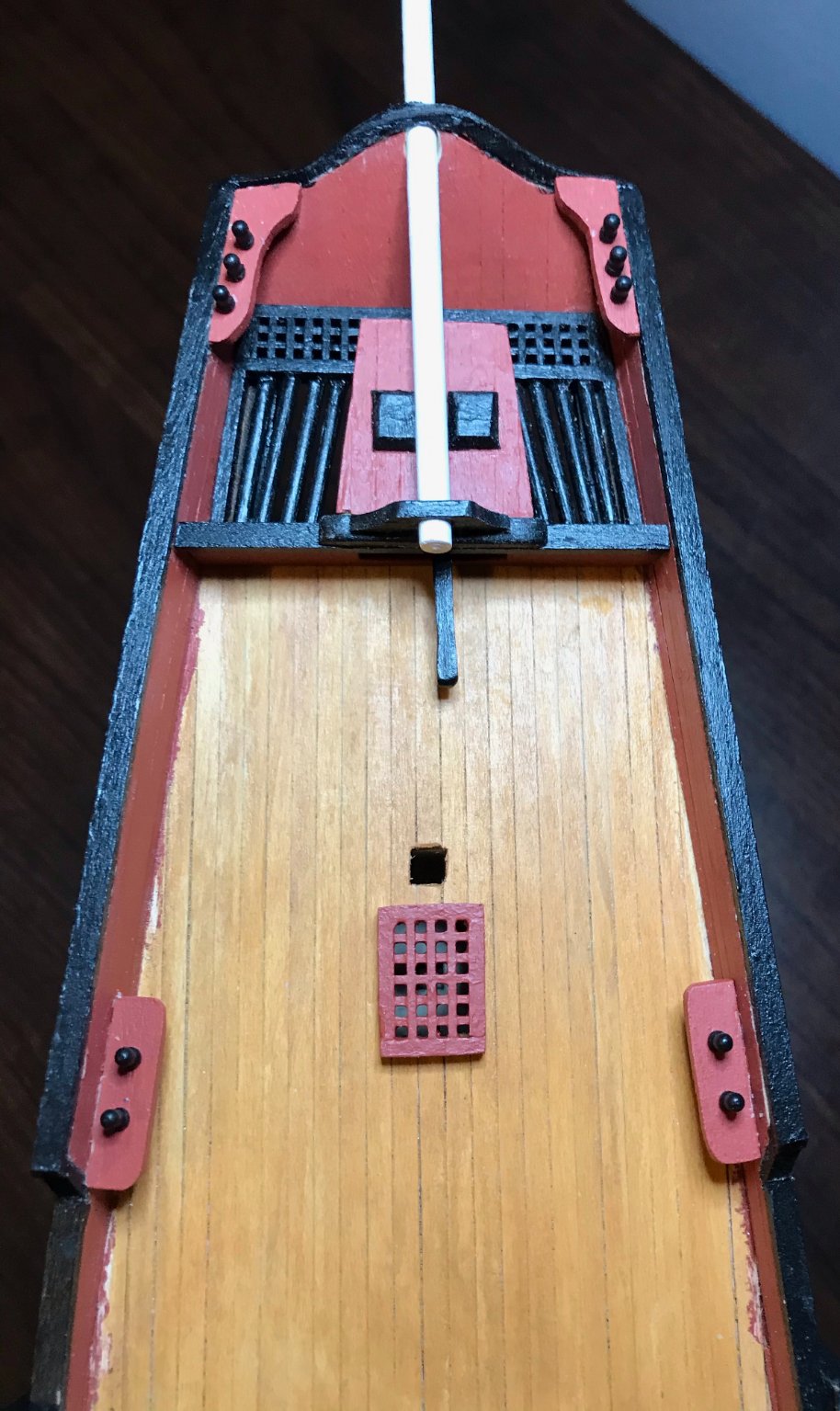
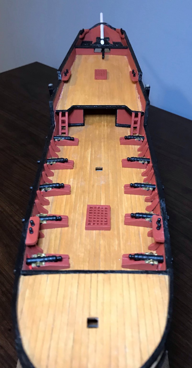
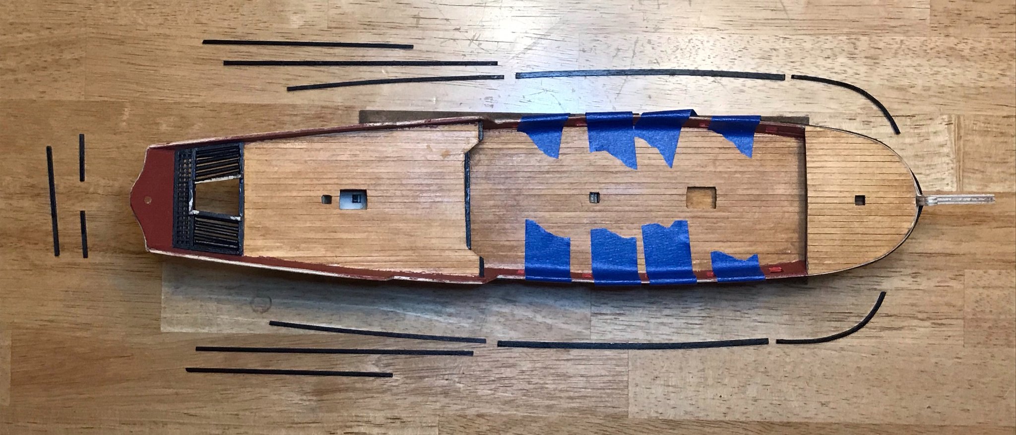
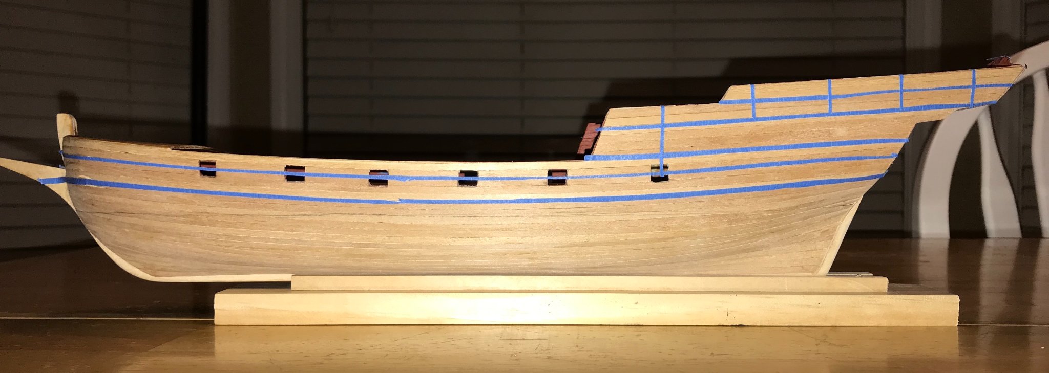
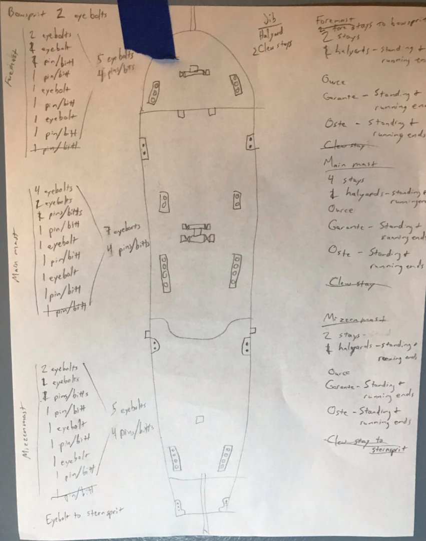
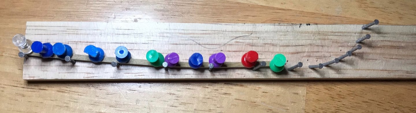
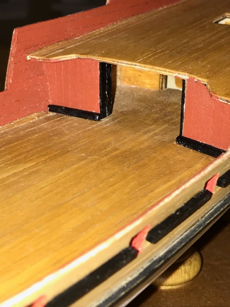
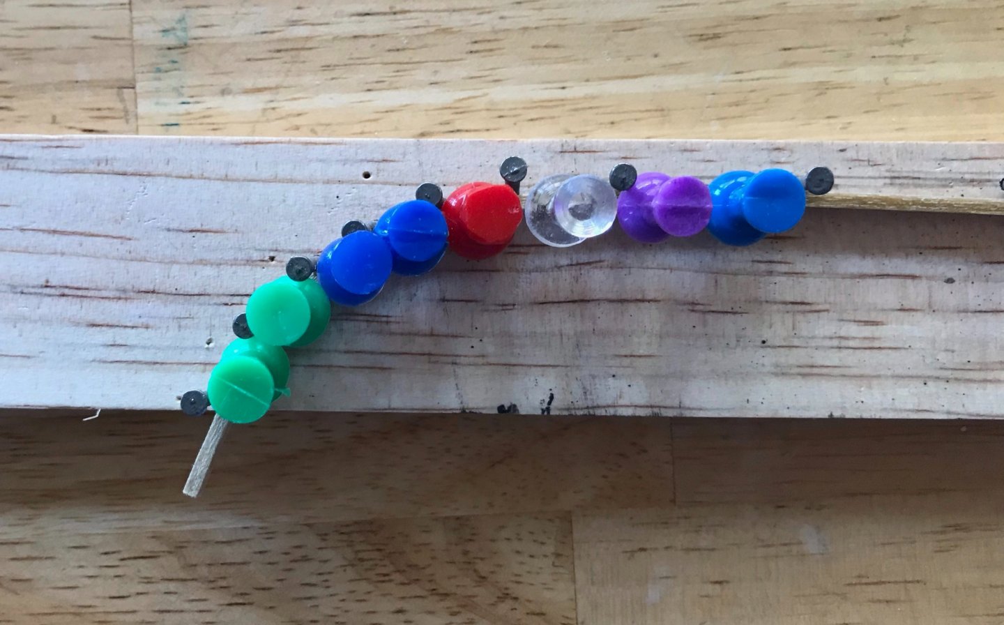
It's so satisfying to draw big red X's in the instructions and plans as I finish steps! The glue is still drying, but I've finished and installed the bulwark supports and belaying pin racks. It was really striking to notice how much of a difference the supports made in terms of the overall impression! A few photos, beginning with details of the maindeck and the aftdeck/rudder well. Then a couple shots of the full ship. As I was working on the belaying pin racks, I realized I had a problem. There are no instructions for the rigging and the rigging plans are a real mess. There are 56 connection points for the rigging (only 14 of which have been installed so far). In the plans, not all of them are used and most of the belaying pins have two or three ropes connecting to them—I have very little practical experience with sailing, but it just doesn't seem like a great idea to have three pieces of the running rigging belayed on a single pin! So, I drew up my own rigging plans. After a couple of drafts, I came up with the sketch below (which are taped onto the wall above my workspace, hence the piece of blue tape). The numbers down the left side of the paper are for one side of the ship. The kit doesn't come with sails, but I purchased the sail kit from Mantua and am planning to install them. With three lateen sails and a jib, I'll need 61 connection points. (Actually, maybe 64...I'm still working out exactly what needs to be done with the clews of the lateen sails.) I set about studying images of xebecs from the Musée Nationale de la Marine and reading Daniel Lescallier's 1791 Traité pratique du gréement des vaisseaux et d'autres batimens de mer (Practical Treatise on the Rigging of Ships-of-the-Line and Other Boats, of which vol. 1 is the text and vol. 2 is the illustrations). Based on that research, I discovered that some of the rigging was usually attached to a lower rail on the bulwark supports. Even though the kit doesn't call for one, I have started adding such a rail, which should get me all of the points that I need. The terminology may be unfamiliar to some, so quick explanations. Ources, garantes, and ostes are some of the French terms for the rigging of a lateen sail. The ources are two ropes at the bottom end of the antenne (the antenna or yard); these are the primary ropes for adjusting the antenne to catch the wind better. The antenne connects to the mast about a third of the way up its length. The garantes are two ropes that descend from a pendent about two-thirds of the way up the antenne's length; on a ship this size, the garantes are the primary ropes for swinging the antenne. The ostes are two ropes that descend from a pendent at the top of the antenne and seem to be there primarily for stability. The ostes are also run through the clew of the sail, before separating to be fixed at belaying pins or bitts.


- 79 replies
-
- 3
-
-
- sergal
- sciabecco francese
- (and 1 more)
-
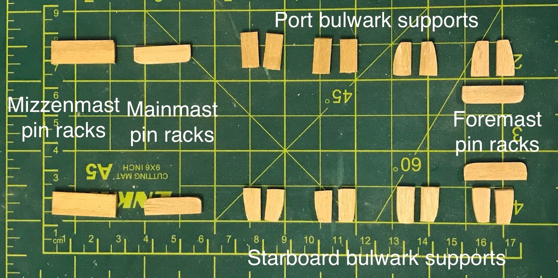
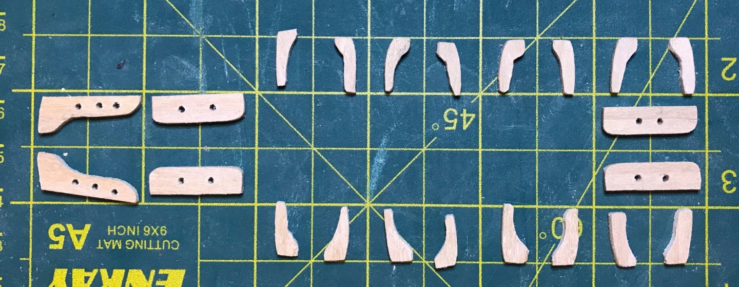
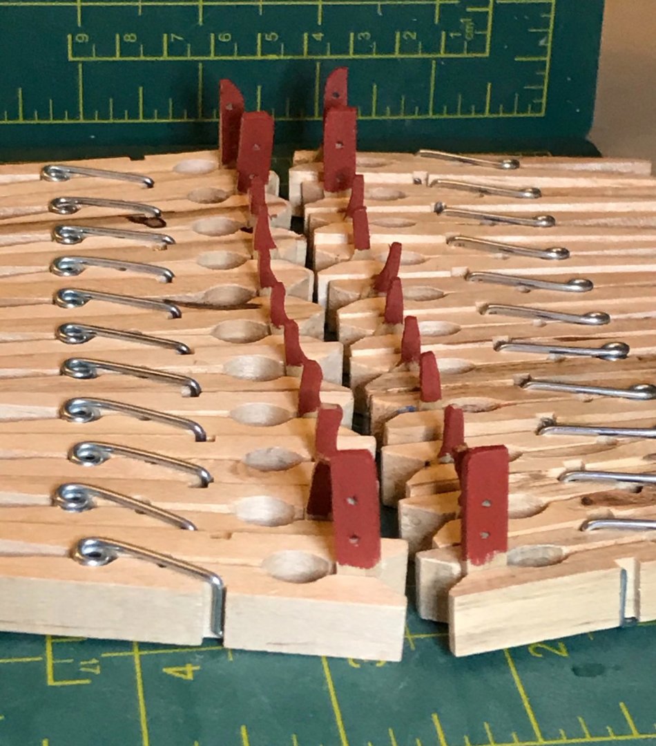
I've been continuing to work on the pin racks and bulwark supports. First, I measured out and planned the inboard shape of the supports and the mizzenmast pin racks. I shaded the portions that needed to be sanded out. Then, I used the Dremel, a round file, and a sanding stick to do the shaping. The bulwark supports aren't perfectly consistent and the spacing of the drill holes aren't perfect, but I'm reasonably happy with how they turned out. And now, I'm started painting them. With 22 small pieces, this step is not a speedy process! First coat is on one half (or so) of each piece.
- 79 replies
-
- 1
-
-
- sergal
- sciabecco francese
- (and 1 more)
-
Hi MT, My current build also uses lateen sails, so I've been continuing to look for good videos of how to rig them. There's a pretty recent video from a guy in Portugal that's better than anything I watched while building the Provençale. (I just discovered I can embed it in the post, so you'll find it below!) He has shot a bunch of videos in this boat. While this one includes an explanation of the rigging system, I've also found it helpful to just watch a bunch of his other videos to see the rigging in action. Hope this helps! Hake
-
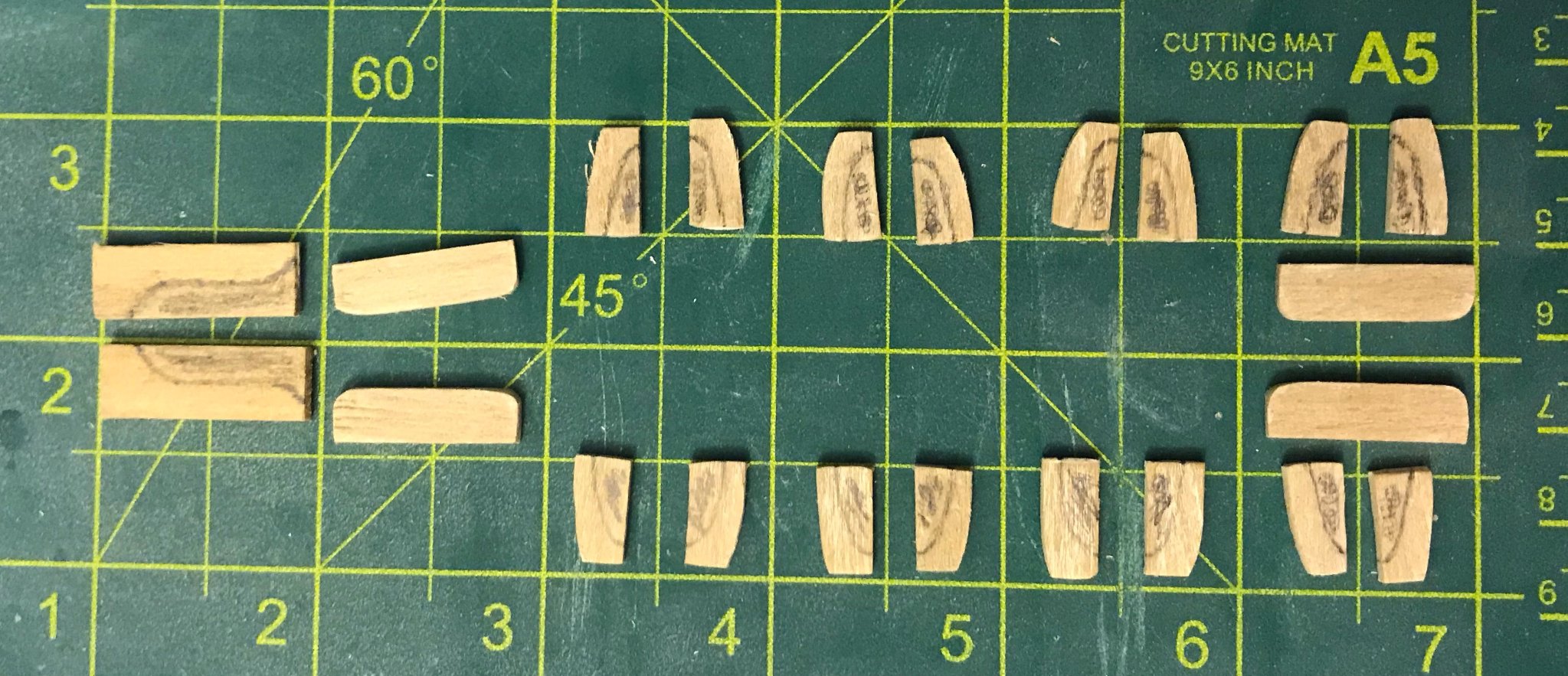
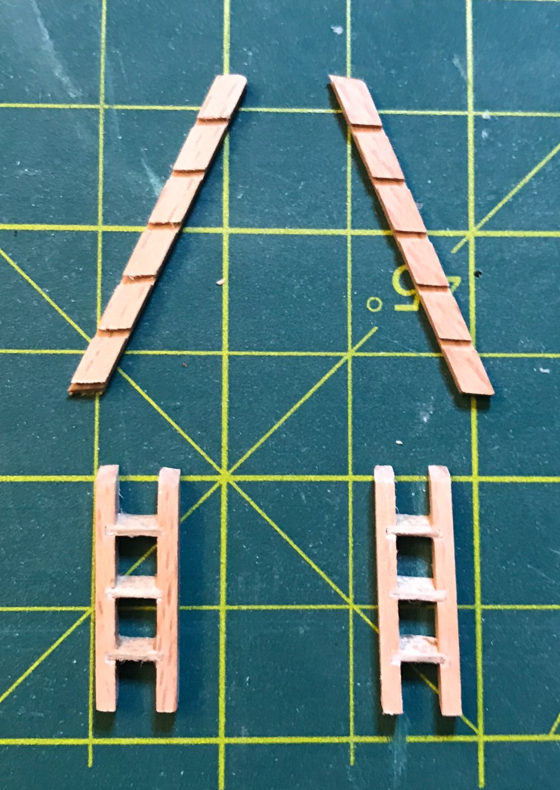
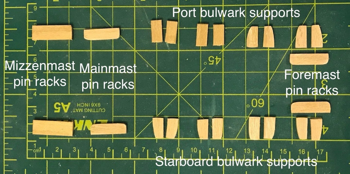
Today, I finished and installed the companionways. There are two of them, which go from the maindeck up to the aftdeck on either side of the ship. The sides of the companionways come precut (though very generously so; there's more than twice what's needed). The steps are from a plank of 1x3 walnut packaged with the sides. The first photo shows some of the excess precut sides and the two companionways after assembly. The second photo shows them painted and installed. They turned out fine, but the scale of the steps is wildly off. At 1:49 scale, those steps would be 4 feet apart—I have long legs, but that's a bit much even for me! At first, I tried using a file to add slots for four more steps, which would put the steps 2 feet apart...but I realized that I just don't have the right tools to do that well. So, I decided to just go with it. If you're reading this and plan to do the kit, you might consider whether you want to cop out like I did or if you would rather find a plan for more realistic companionways. I've also cut the pieces for the belaying pin racks and bulwark supports. There's a lot left to do here, but I figured I'd share a photo near the starting point. The foremast and mainmast belaying pin racks are identical. I've rounded the inboard corners, but haven't yet checked if I need to do any shaping on the side attached to the bulwarks. The mizzenmast pin rack will require considerably more shaping, but I haven't started that. I'm part way through shaping the bulwark supports to the bulwark. Once I'm done with that, I'll shape the inboard side. There are two supports between each of cannon that are out in the open, so there's a fair amount of finicky and repetitive work to do before the job is done.

- 79 replies
-
- 1
-
-
- sergal
- sciabecco francese
- (and 1 more)
-
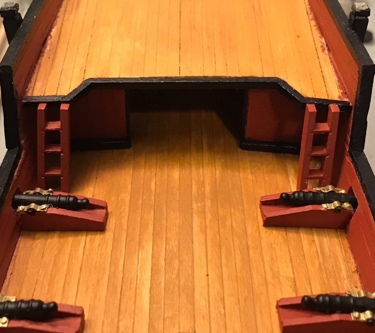
Now that I've remounted the ship on it's stand, I've been able to focus on a few smaller tasks. First, I've installed all the cannon and hatches, since I had built them a while back. There are ten cannon visible and two more in the cabin, directly below the supports for the swivel guns. I've also been getting some practice with lashing and wooldings. I lashed the bowsprit to the head; as expected, the port headrail is now staying put. The lashing is a clove hitch, five turns around everything, and another clove hitch at the other end, with Dritz Fray Check used as glue to hold the knots in place. As for the wooldings, I've finished one anchor stock and tomorrow will do the last one on the other anchor. This took a bit of experimentation, but I finally worked out a system and am able to tie each one in only a minute or two, using common whipping. I pin one end of the thread to the stock using a small binder clip. Then I make a smallish loop on top of the stock. I hold the end of the loop in place with my left index finger (I hold the anchor in my left hand by opposite half of the stock). After making five turns around the stock, I pin the working end of the thread against the stock with my left index finger (to keep the tension on the working end; no need for it to stay on the loop anymore). With fine-point tweezers, I pass the working end through the loop and pull the knot to. Next, I use the tweezers to compress the turns around the stock, so they lay tightly against one another. I switch to flat tip tweezers, one in each hand, in order to really pull the knot tightly. After that, I glue everything into place with a couple drops of Fray Check. Once that dries, I trim off the loose ends and add a drop of Fray Check to each to prevent any fraying. Next steps, after finishing the last woolding: finish and install the companionways (which I've started painting) and start on the belaying pin racks.
- 79 replies
-
- 1
-
-
- sergal
- sciabecco francese
- (and 1 more)
-
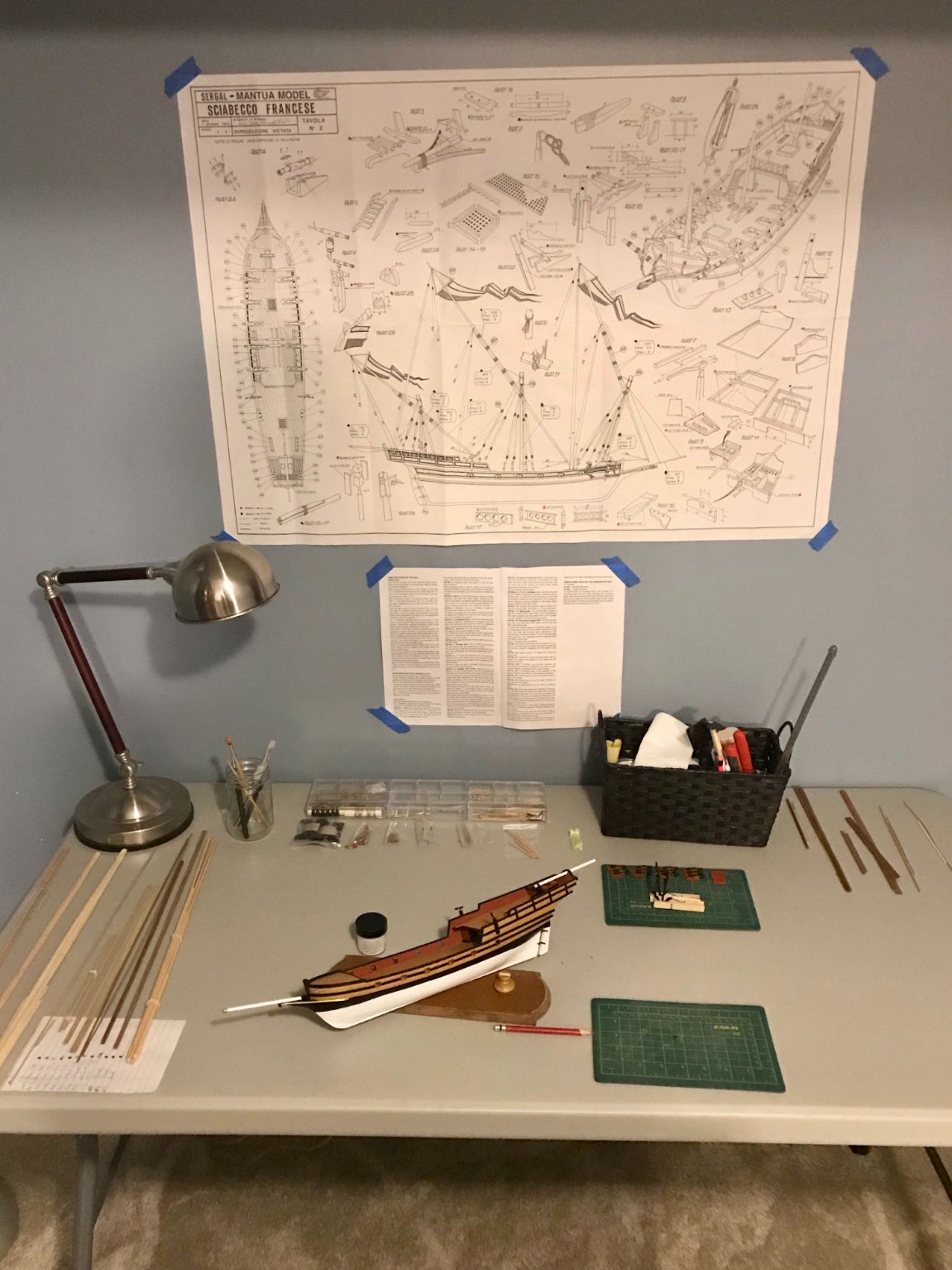
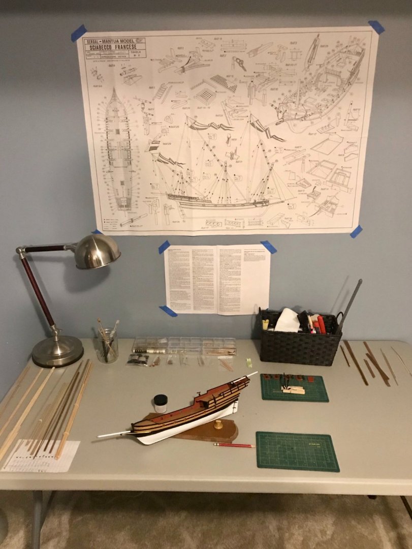
It was the best of days, it was the worst of days... Today, we finally finished restoring the basement, after a broken sewer line. Fresh paint, after a contractor installed new drywall and carpet. (The carpet isn't ideal for shipbuilding, of course, but we're hoping it'll help insulate the basement and dampen the sound when I'm practicing trombone.) Tonight, I moved all of my shipbuilding stuff out of the kitchen and set up again in my basement workspace. Most of the tools are on the shelves just out of frame to the left. But the plans are up on the wall, along with the instructions (yes, there's only a page-and-a-half of instructions for the kit, though the plans are double-sided). The wood stock for this kit is sorted to the left, thread and hardware are up by the tool basket, and scrap wood from previous kits is to the right. Lots of space in the middle for the current project. You'll notice, however, that the xebec is off it's stand, despite my celebratory post a couple of days ago. That's the bad news. While I was brushing on a coat of finish, it took a dive off the stand, bounced off the dining room table, and landed on the hardwood floor. I'd say my kids learned some new words today, but they tell me that they've already heard them in the school lunchroom. Yet, this bad news could be a lot worse. My construction has been solid. The only damage after that fall? The swivel guns and their brackets are loose. So, I need to redo those again (AARGH!) and I need to find a better way to mount the ship on the stand. I had previously just glued it into the slots on the pedestals, but this time I'll add a couple pieces of 2mm brass wire to give additional support.
- 79 replies
-
- 1
-
-
- sergal
- sciabecco francese
- (and 1 more)
-
Thanks, Bob! I had never heard of a xebec before I decided to buy this kit, but I've also fallen in love with the shape. Very sleek! Progress will be slowing down for awhile now. It's Pinewood Derby season around here, and my son and I need to get to work on his car. Then, I'll be preparing for the new semester. So, I'll still get some time in on the xebec, but nothing like the last two or three weeks have been. I'll share more as soon as I have something to share!
- 79 replies
-
- 1
-
-
- sergal
- sciabecco francese
- (and 1 more)
-
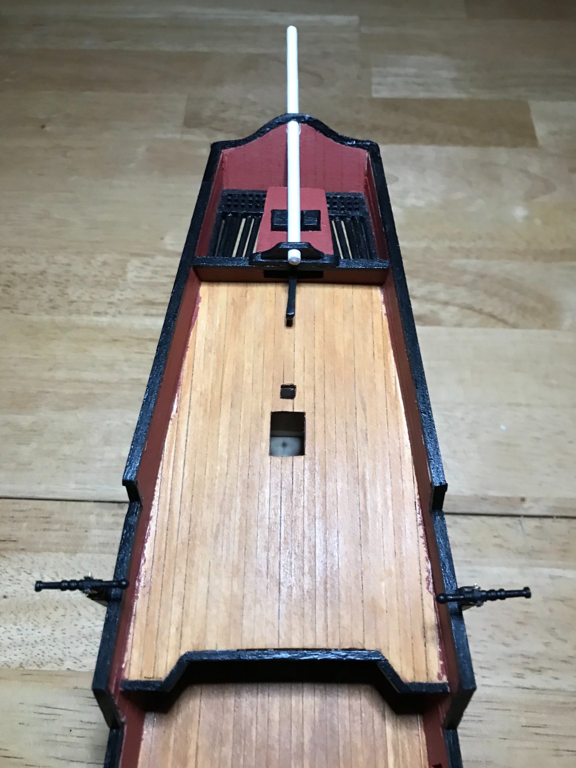
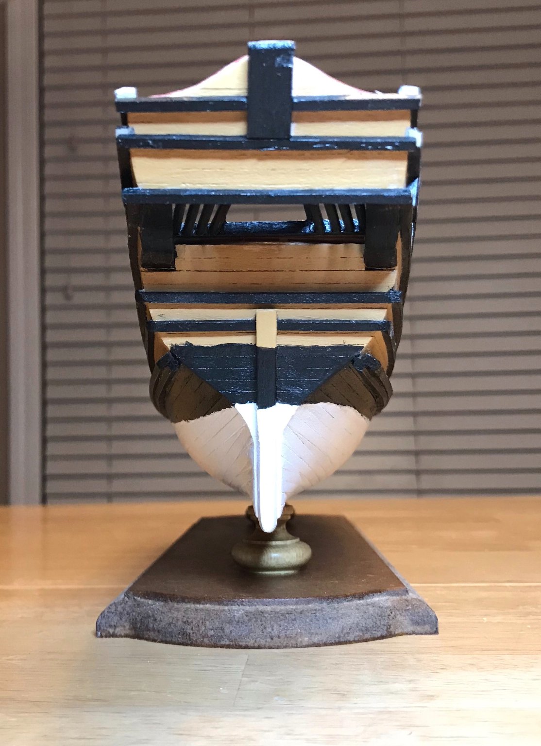
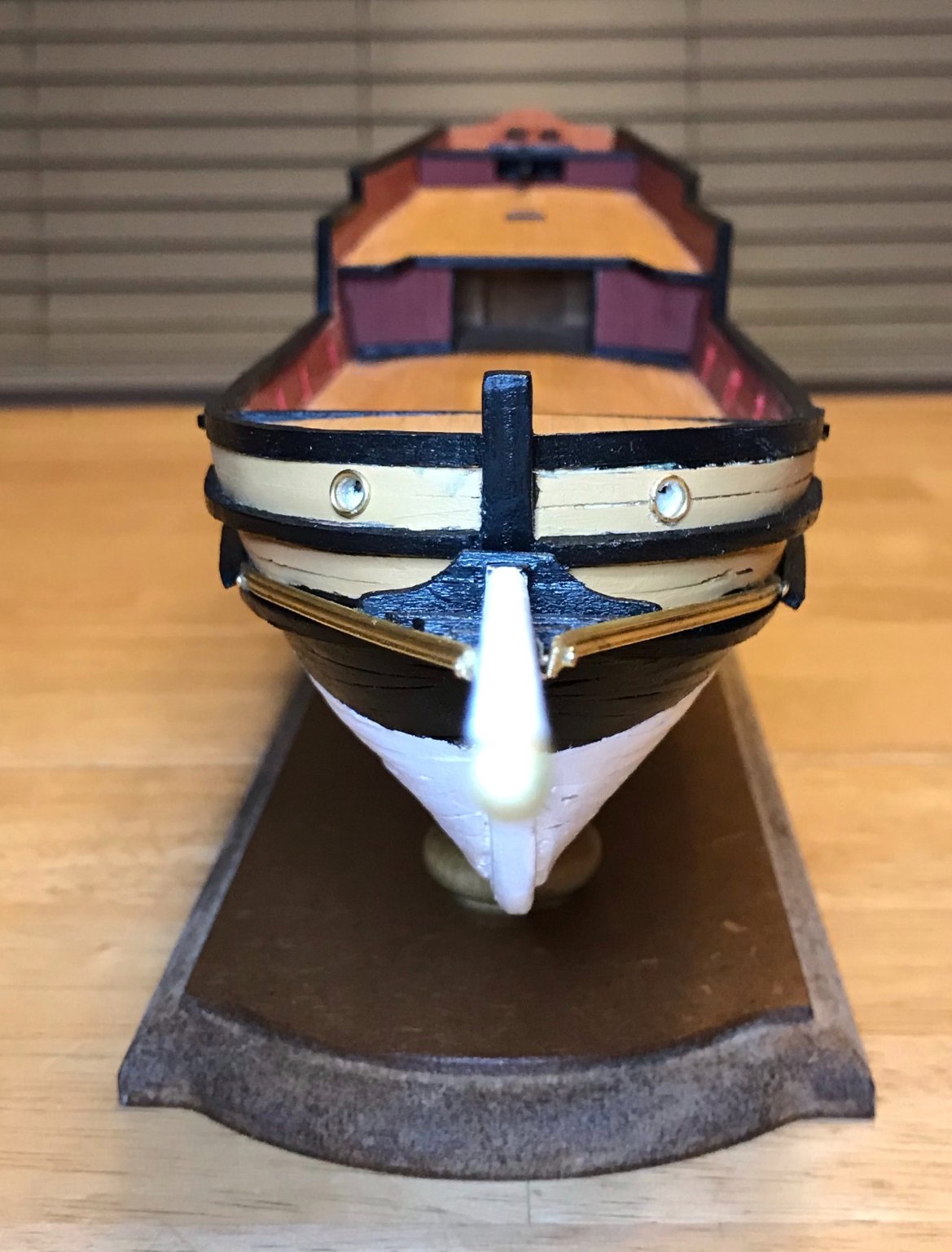
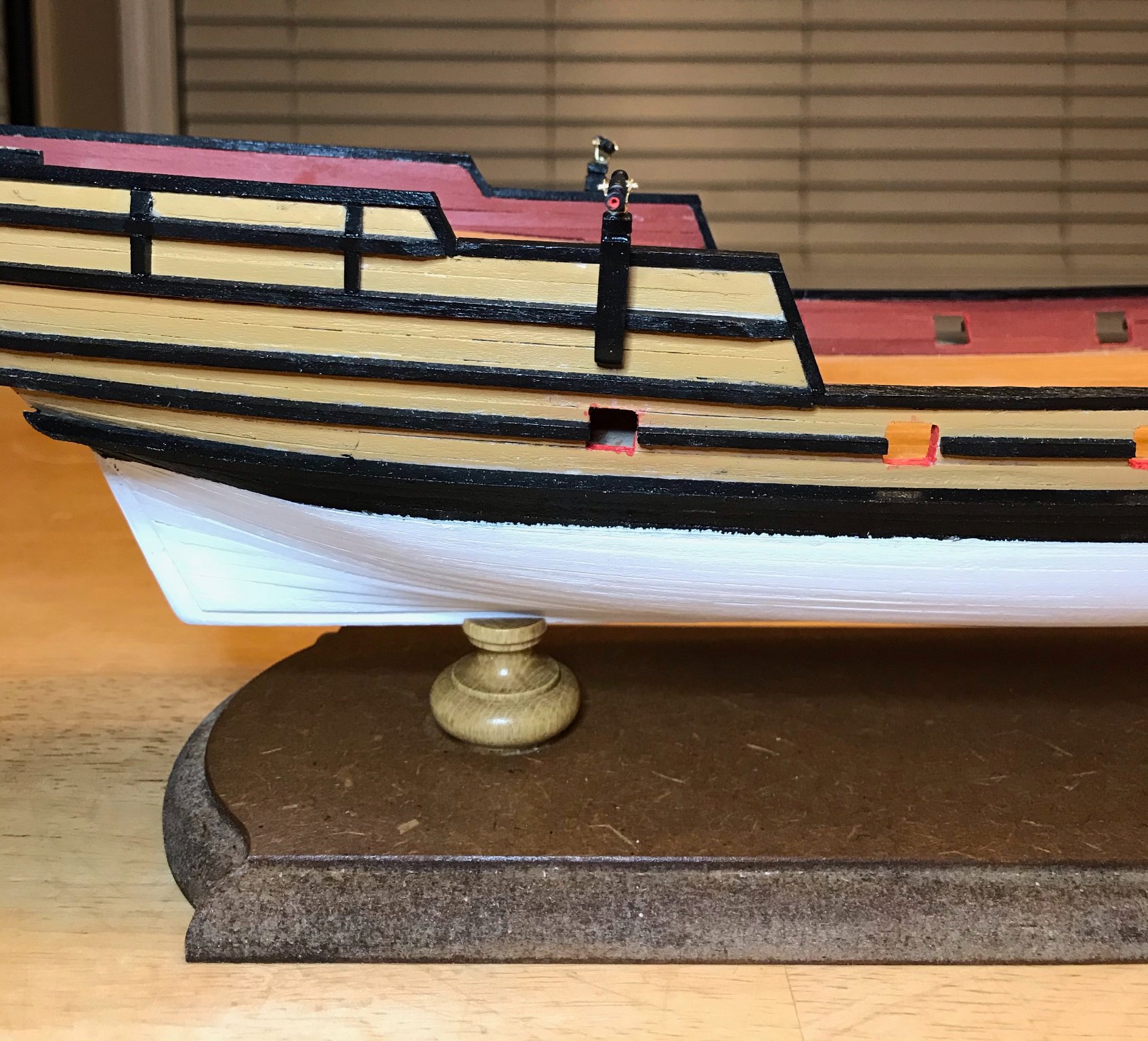
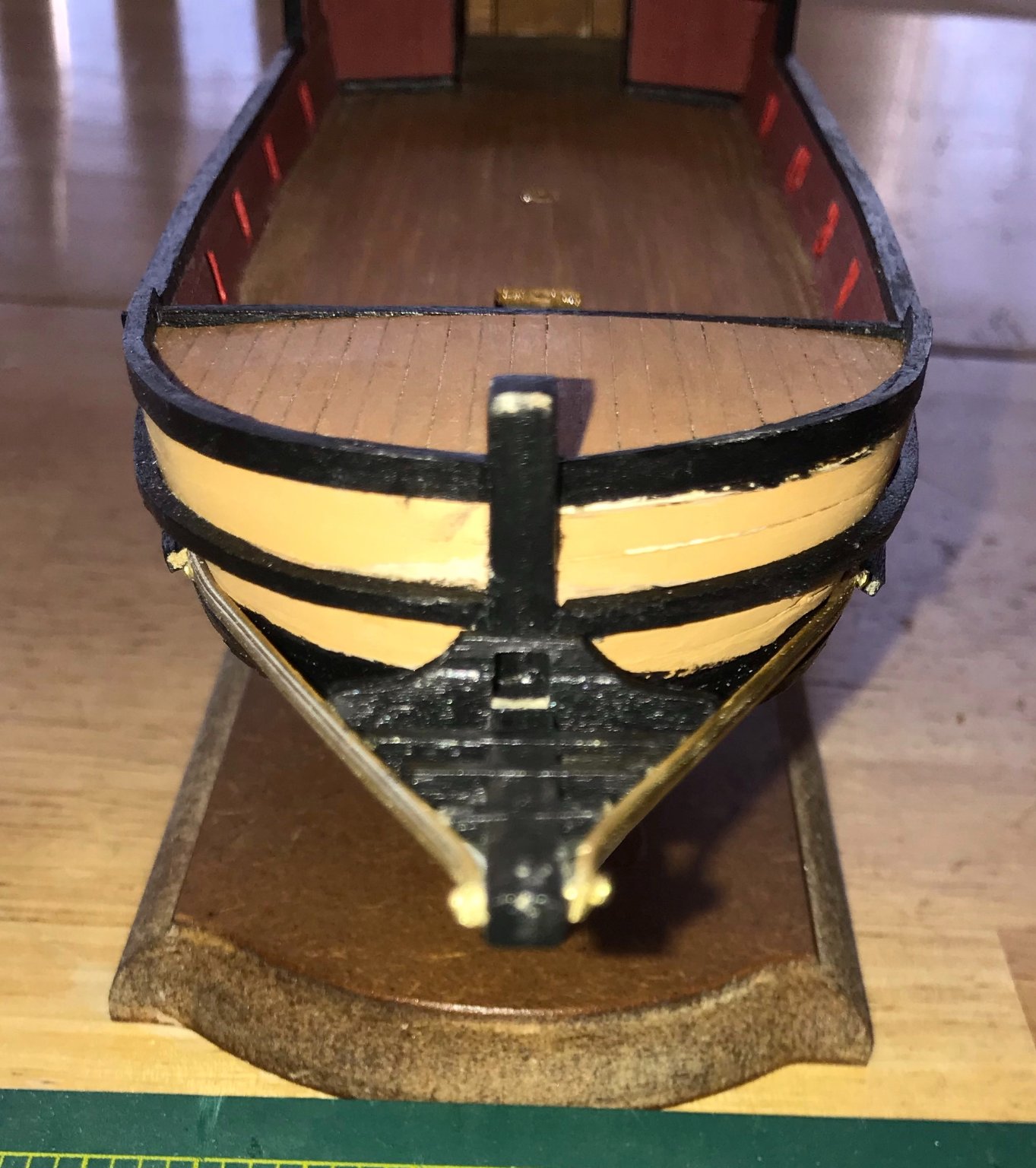
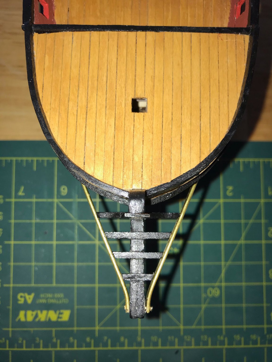
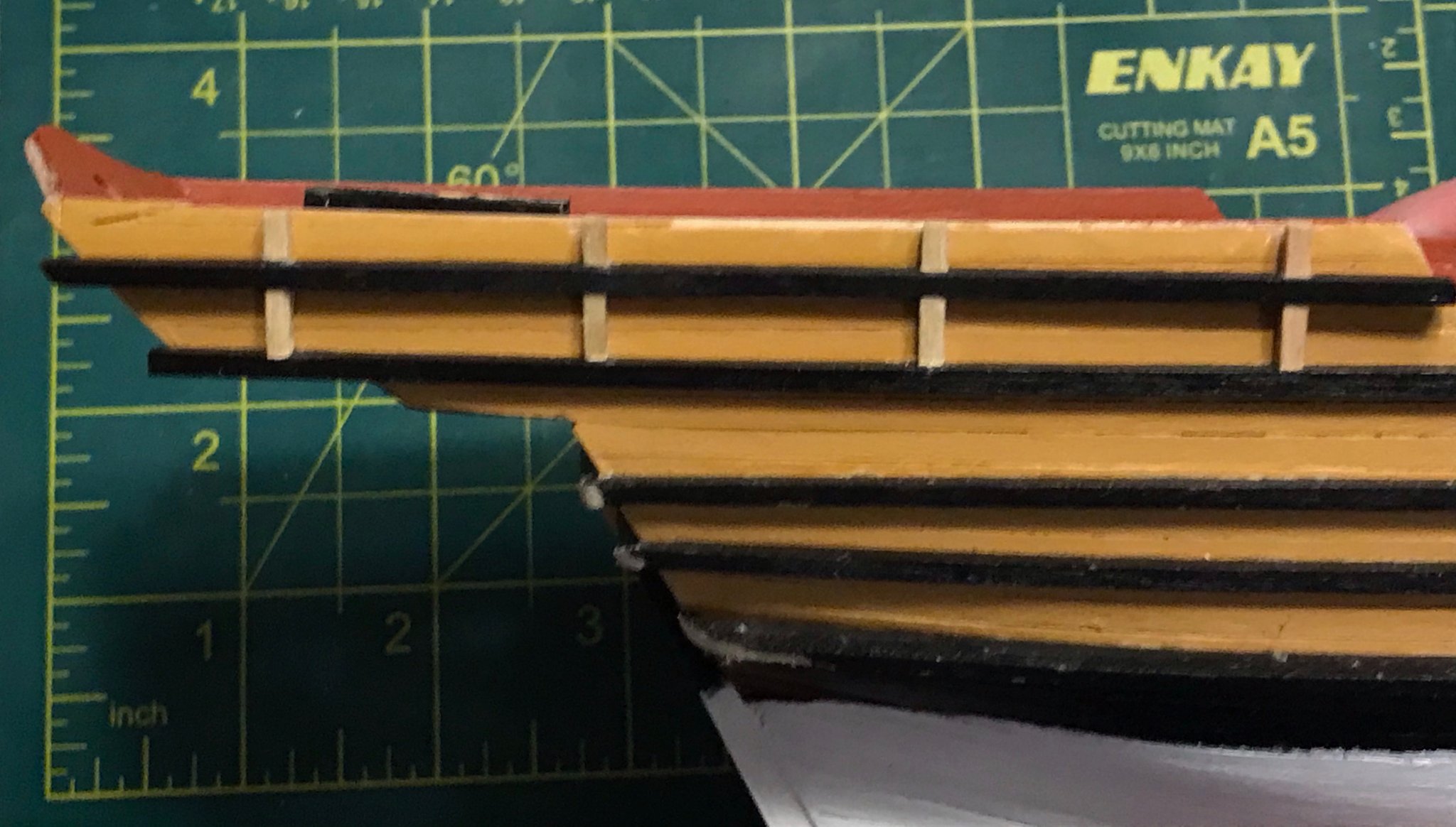
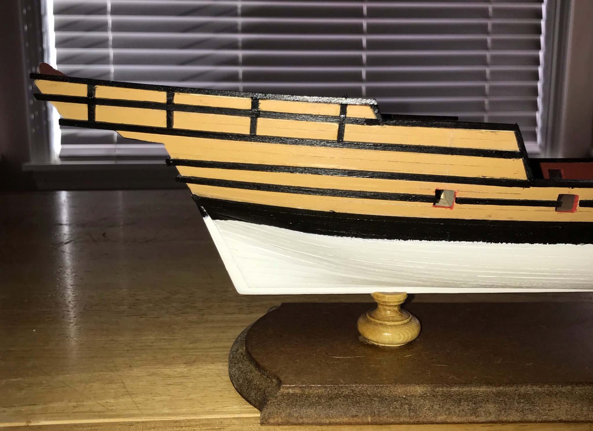
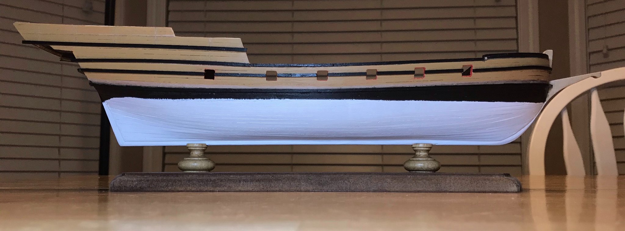
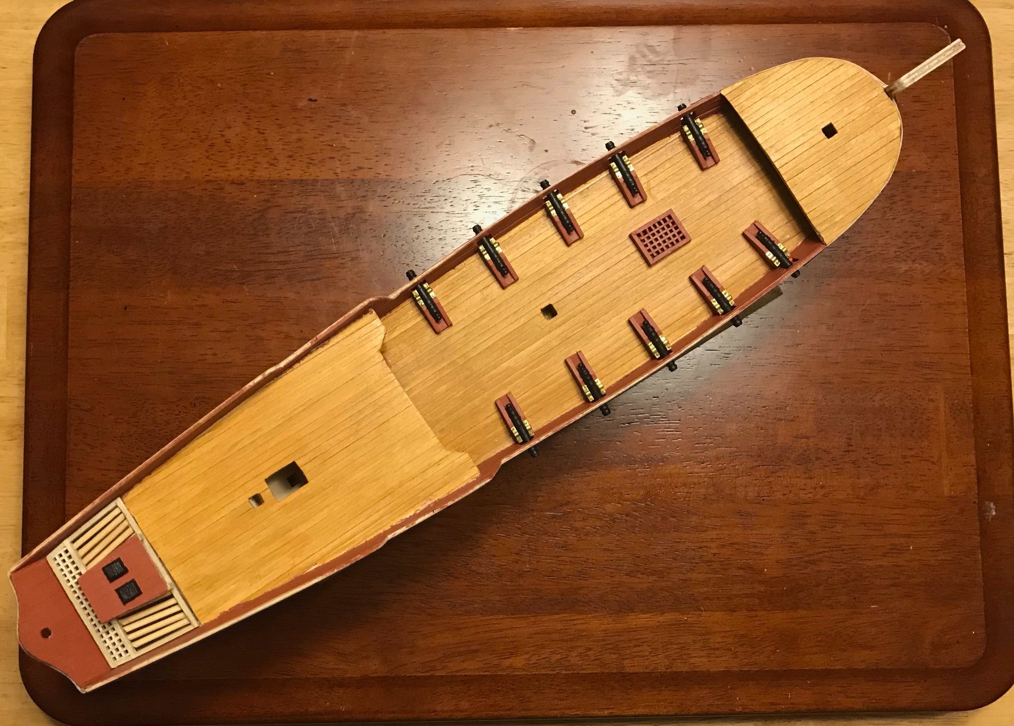
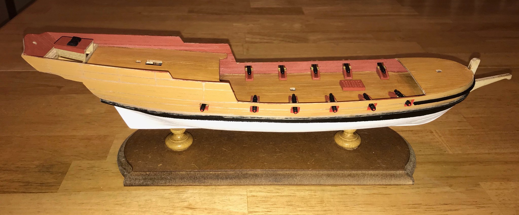
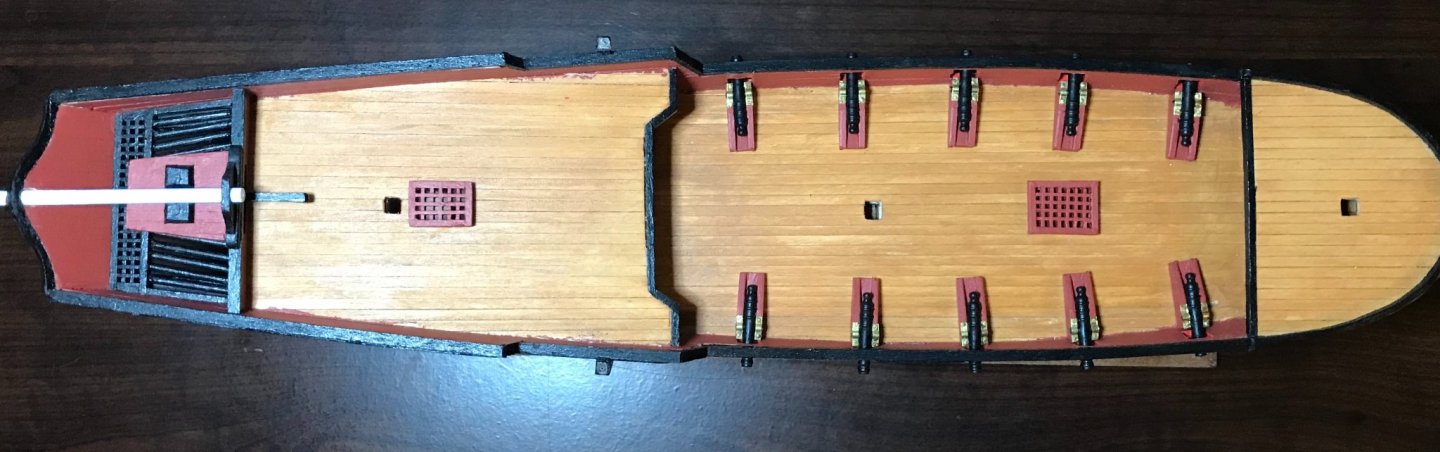
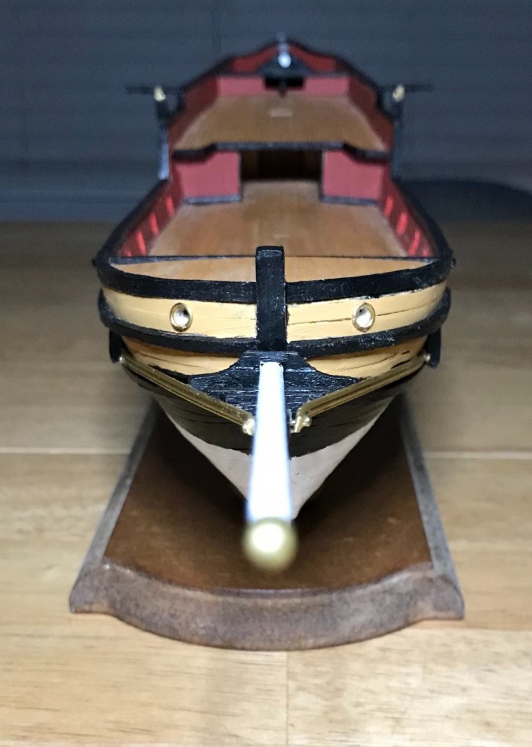
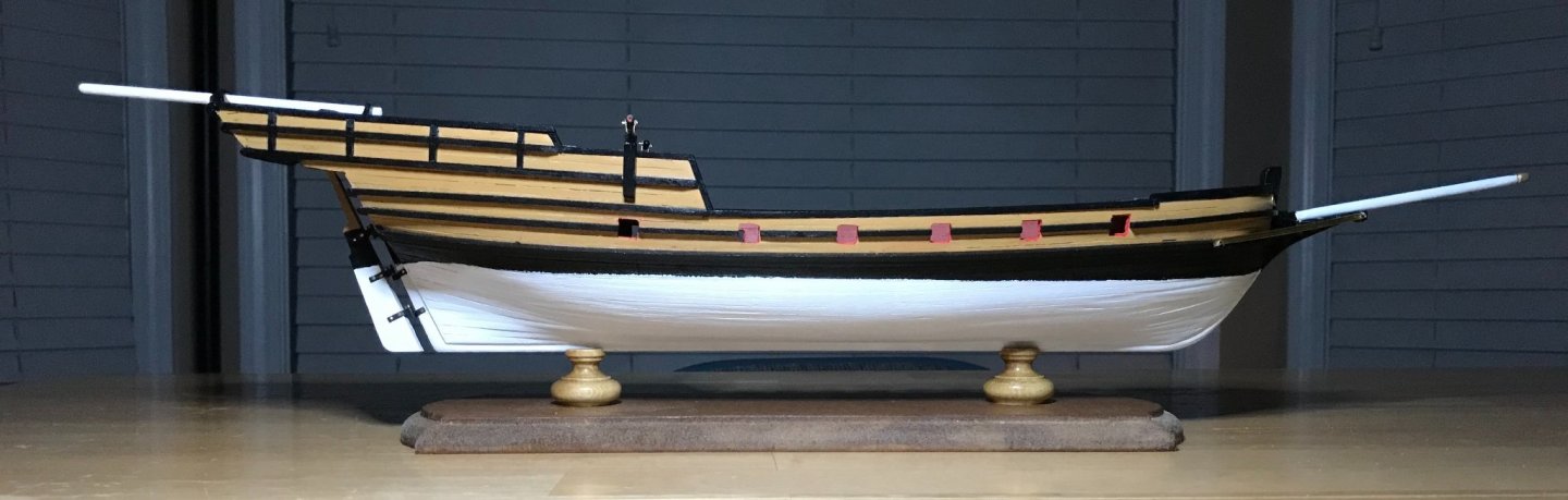
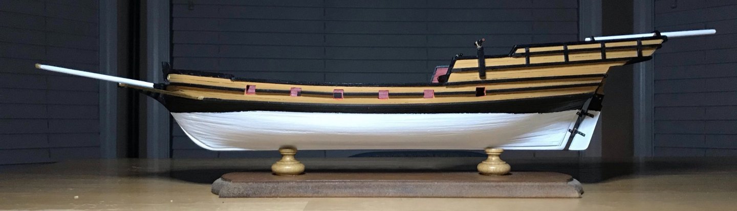
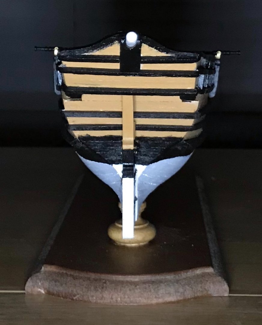
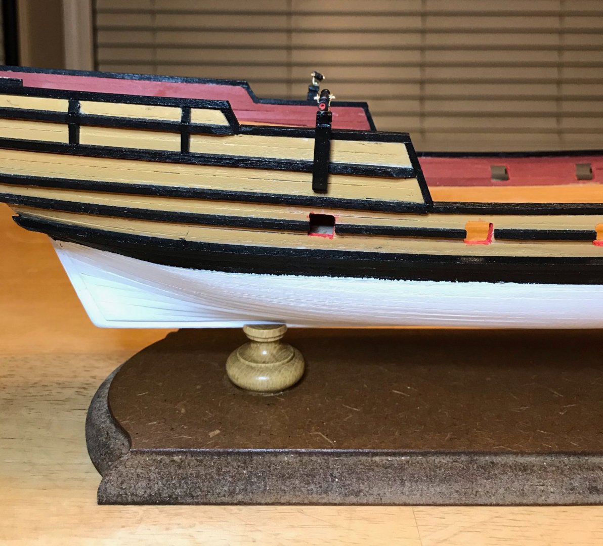
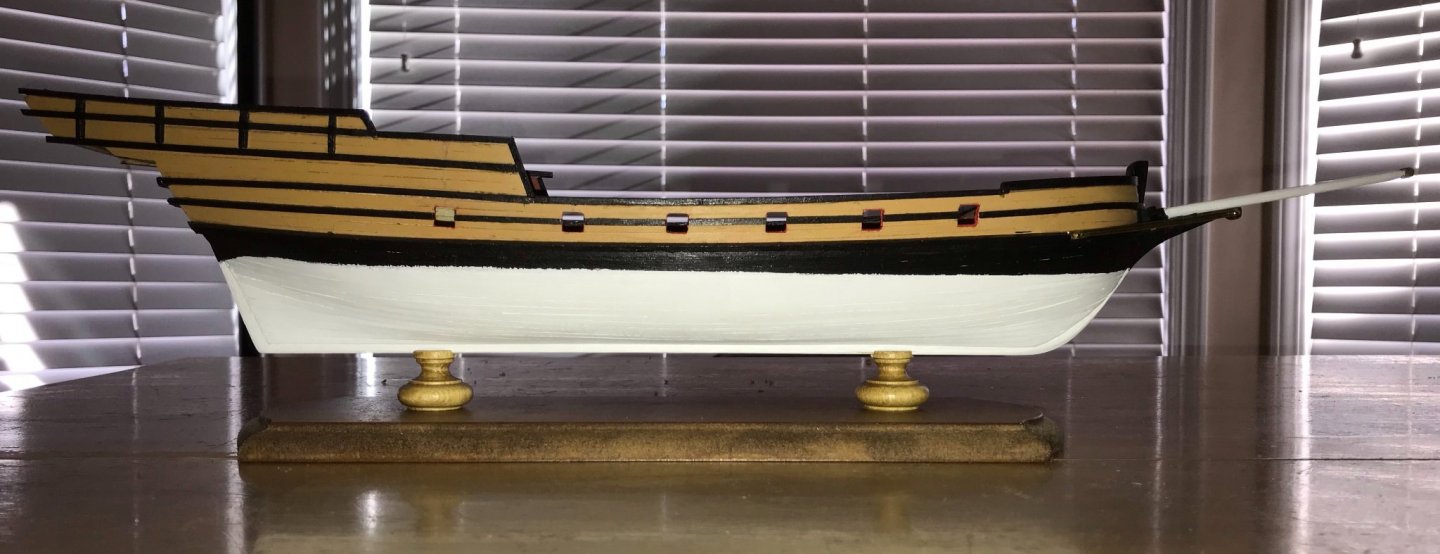
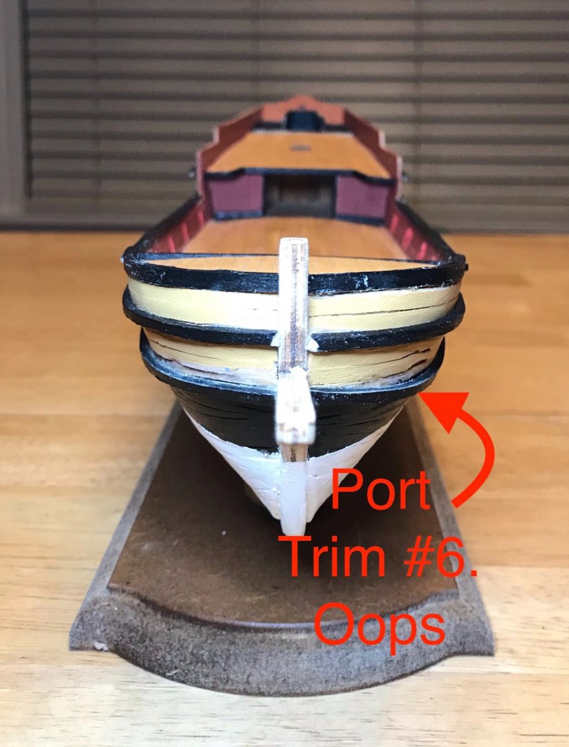
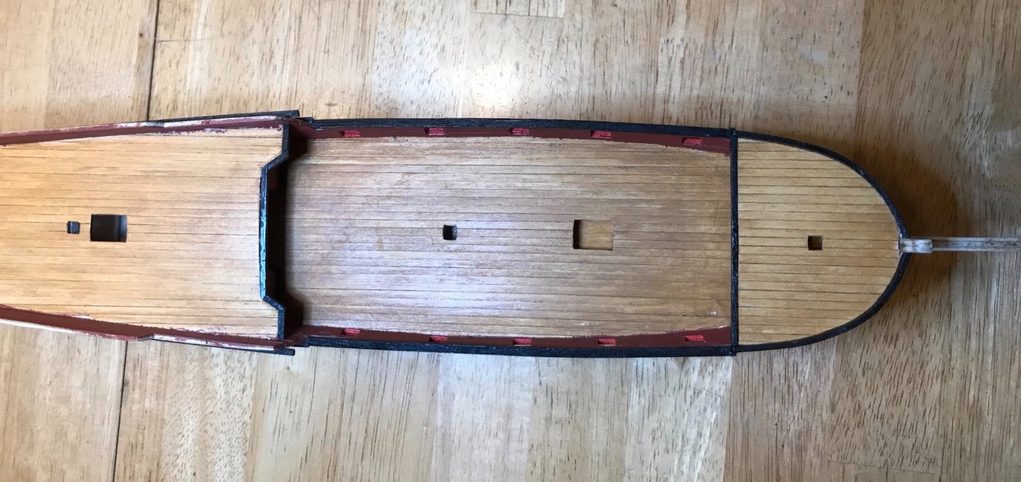
I've just arrived at the next landmark point in the construction of this ship! Except for some finish, the exterior of my xebec is complete! Today, I used the router attachment on my Dremel tool to drill out a new hole for the sternsprit in the upper transom, which allowed me to attach that. There was much trepidation involved and I ended up needing to do some creative filing and touch-up painting after the router slipped. But, in the end, I'm pretty happy with how that turned out. The sternsprit isn't true to the center line, so it's not perfect, but given that it was the first time I did this particular task, it's close enough for jazz. Today I also attached the swivel guns and mounted the ship on its stand. My next work session will focus on applying finish and studying the deck fittings, but for now, some (larger than usual) photos to celebrate! First, a shot of the bow. There's a little issue with the port headrail, which refuses to stay put; after the finish is applied, that should be resolved when I lash the bowsprit down. Next up, an overhead shot of the aftdeck. It's a real shame that the alignment problems with the rudder and sternsprit go in opposite directions. It really exaggerates the issue! Next, starboard and port views. I'm pleased with how the trim ended up! There's one piece that's slightly out of alignment...but it's close enough that I may be the only one who notices! The two swivel guns are lined up with the aft-most gunport...the camera angle makes that look a little funky on the port side. Finally, a shot of the stern. The paint job isn't quite perfect, but otherwise I'm happy with this end. The camera angle makes the alignment of the waterline on the rudder and the hull look funky, but you can see in the other photos that it's okay.

- 79 replies
-
- 3
-
-
- sergal
- sciabecco francese
- (and 1 more)
-
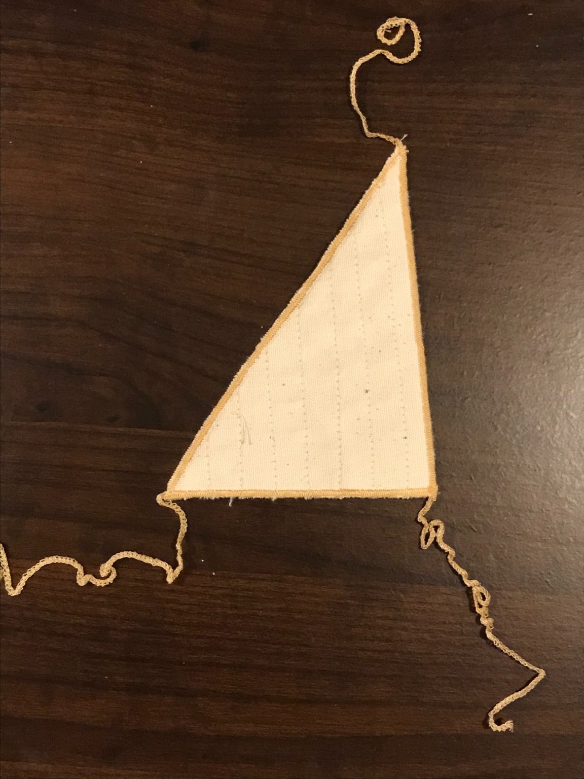
I agree about the bare pole model looking empty. So far my kits have been smaller fishing vessels in 1:20 or 1:25 scale, so I think it's made a lot of sense to have the sails on. My current xebec is in 1:49 scale, but still only has three sails, so is still a much simpler proposition than the Cutty Sark! I'm still a ways off from rigging the sails, but I had pulled them out of the package a while back just to inspect them. With only three sails, they're much simpler to sort. Once I start working on the yards, I'll check the sail sizes...hopefully they're more accurate in my case, but we'll see. Two detailed questions for you, since your sails turned out so well: when you sewed in the rings, did you also cut a hole in the cloth? That is, are the lines running through the ring only, or through the ring and the sail cloth? And second, I assume that your sails also came with a ridiculously excessive amount of edging material (see the photo below)...did you just trim that off at the edge of the sail cloth, or did you use it in some way? Thanks for entertaining these very novice questions! Hake

- 42 replies
-
- 1
-
-
- Cutty Sark
- Sergal
- (and 1 more)
-
Hi BoneDoctor, beautiful work on this Cutty Sark! I have a quick question for you that might help with my current build, Sergal's Sciabecco Francese. Is your sail set the one sold by Mantua? If so, can you share some detail on how you went from the sails as they arrived to the sails as installed? I picked up the comparable set for my ship and am pretty confused by the instructions that came with them. Thanks in advance if you're able to offer any insight. I look forward to following the rest of your build!
- 42 replies
-
- 1
-
-
- Cutty Sark
- Sergal
- (and 1 more)
-
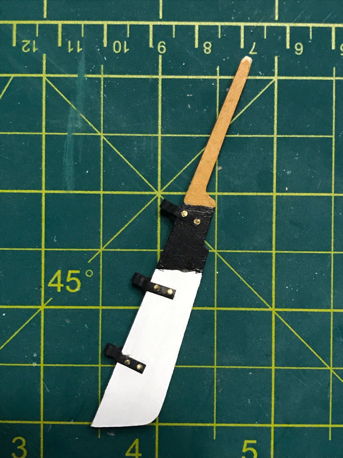
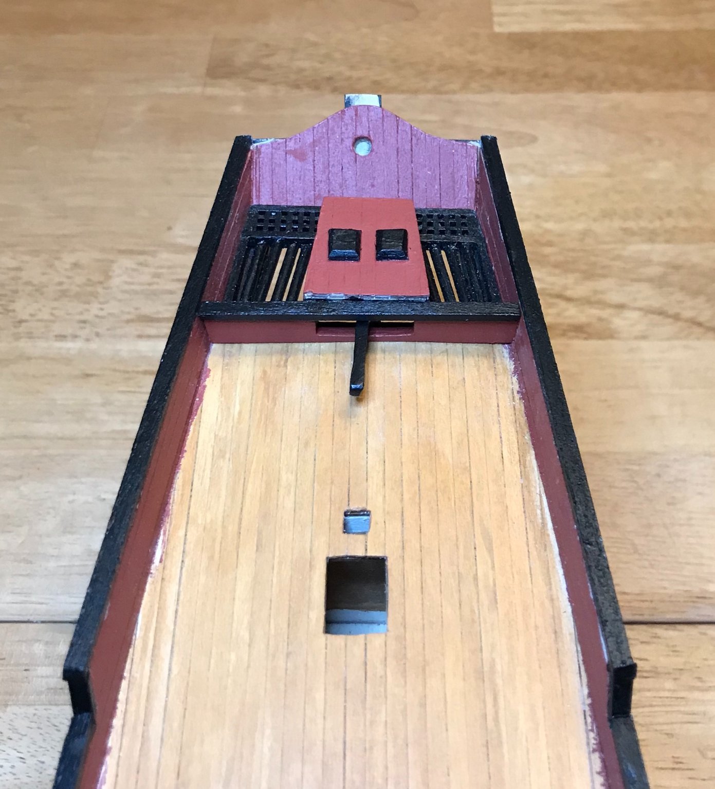
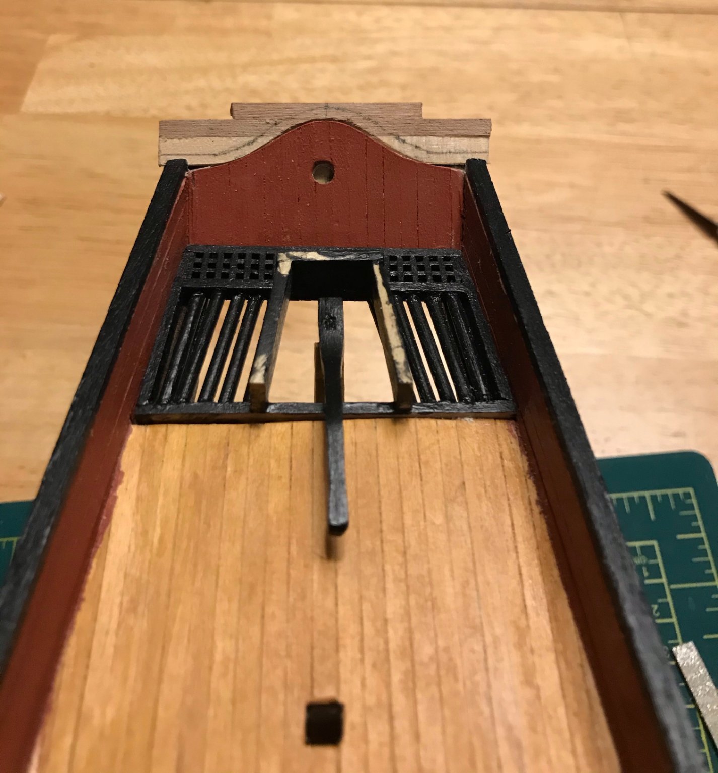
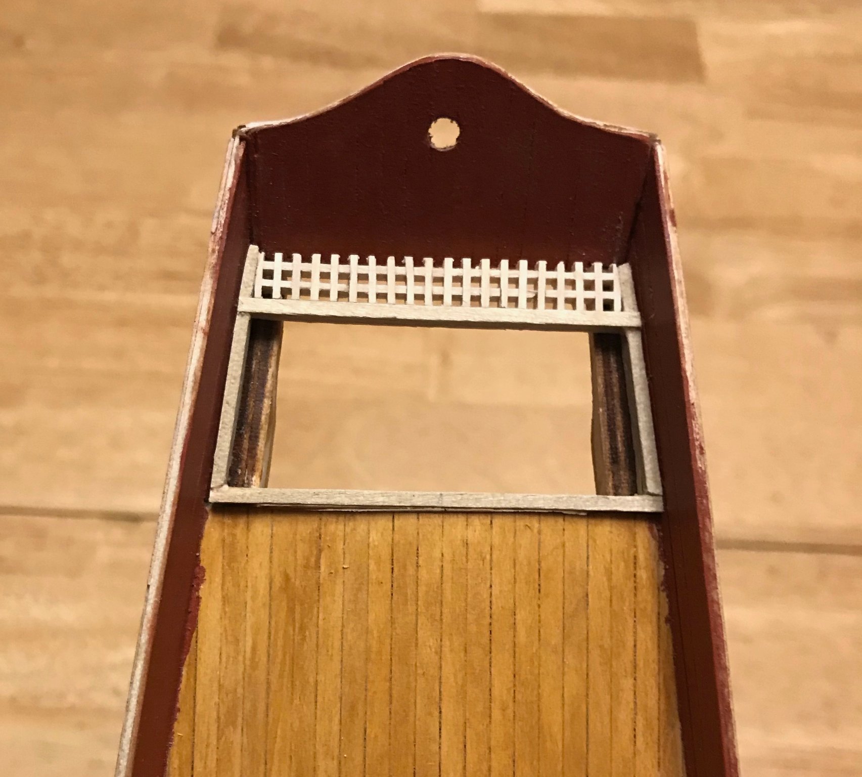
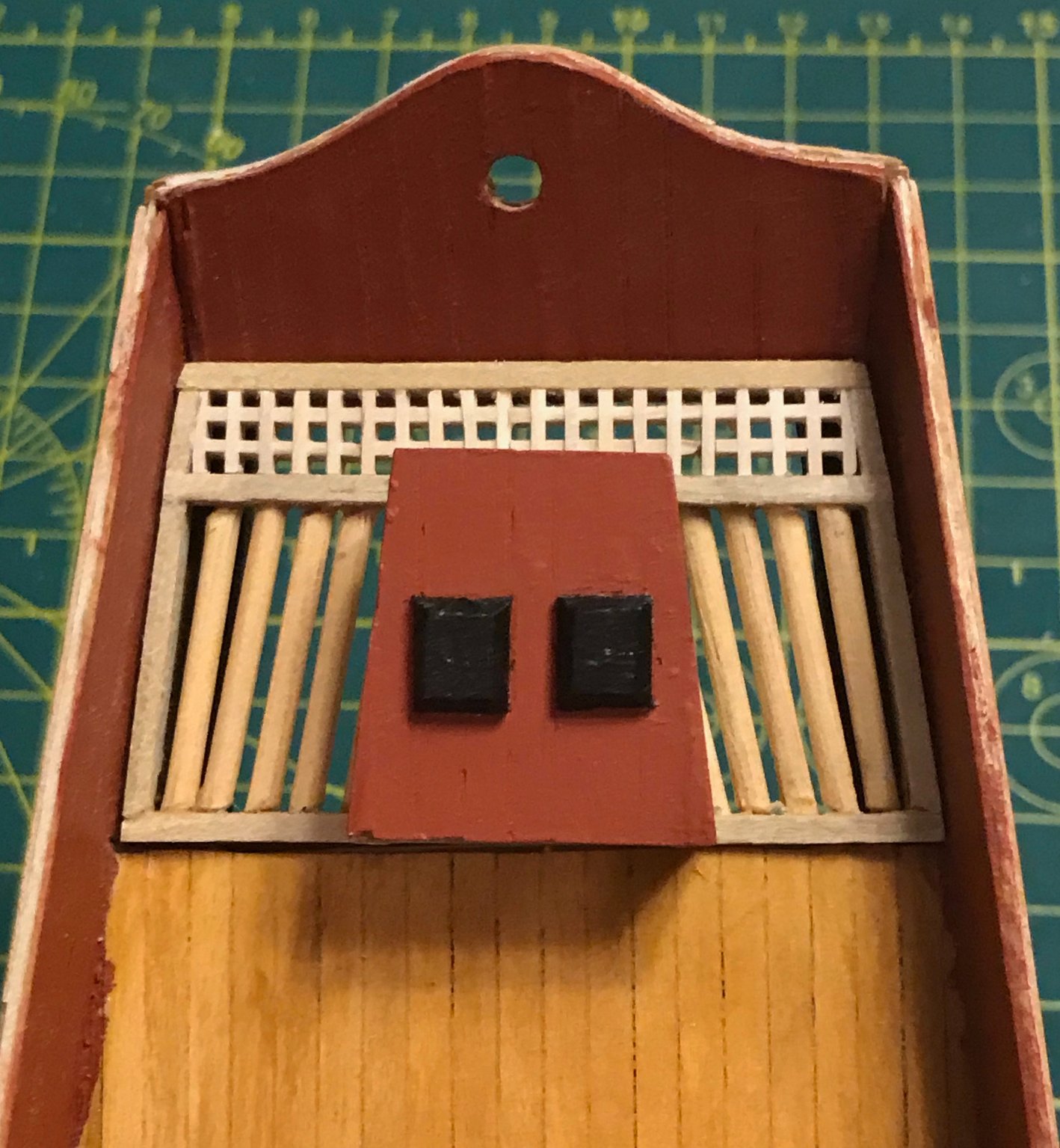
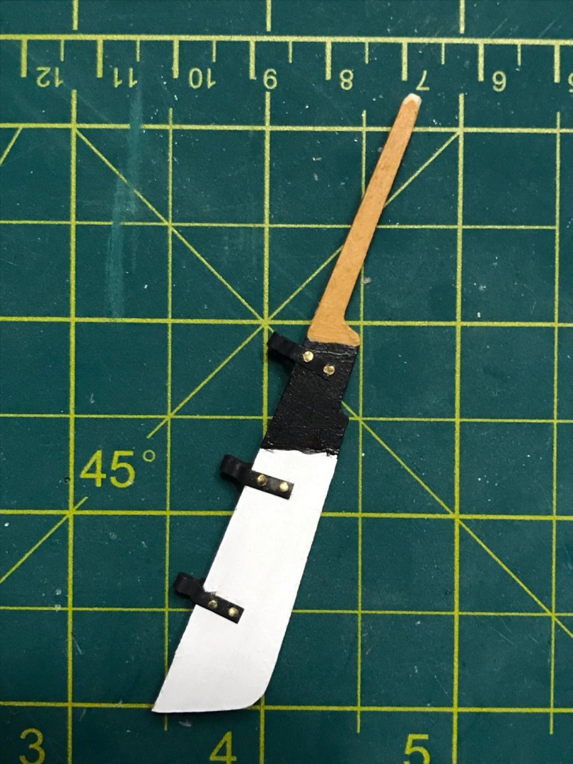
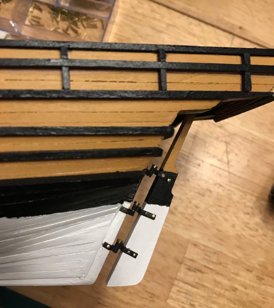
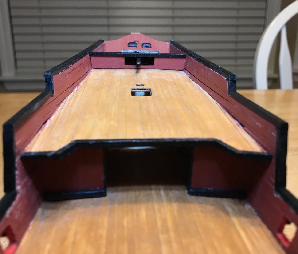
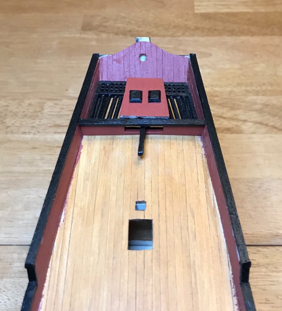
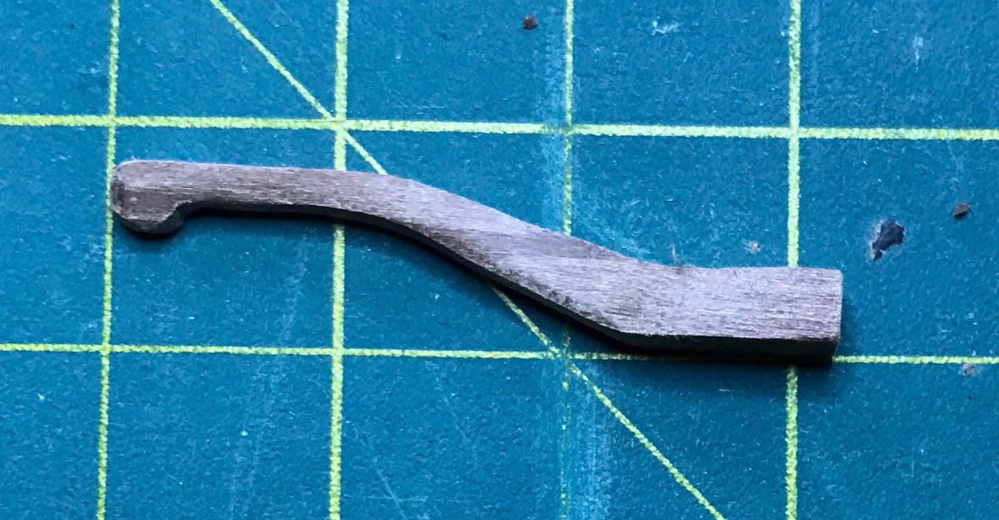
Thanks, Bob! Nice to hear from you! Three more updates tonight. First, I've finished and installed the rudder. I'm mostly happy with it. I'm satisfied with how both the tiller and rudder turned out, individually. When it came time to join them, though? I'm not sure if the problem is my novice skill set or not having the right tool for the job—probably both—but the tiller isn't true to the center line and it's a good thing that the joint is completely hidden once the ship is finished! If anybody has tips on cutting the angled hole into the tiller (including how to determine the angle before cutting), I'd appreciate it. The step is done for this ship, but the advice will be very helpful once I do my next one. Anyhow, I previously posted about shaping the tiller, so will skip over that here. The first photo is of dry-fitting the tiller onto the rudder. Next is the installation of the rudder hinges. In previous kits, I've really struggled with this step. But this time, things went remarkably smoothly! Since the rudder is a little thicker than the ones in my previous kits, I could trim the pins a little longer and that really made all the difference. There is a small issue with the middle hinge on the sternpost, since that ended up going in about .5mm too low (you can see this in the third photo). But apart from that, everything lined up perfectly and the hinge pins dropped right in. And a couple shots of the rudder well assembly, with the rudder installed. One without the rudder well cover and the other with it. The last step was to build and install the dividing wall between the aftdeck and the rudder well assembly. This took some rather finicky work with the file. I had to account for the camber of the deck, as well as bevel the ends of the planks to account for the shape of the bulwarks, which widen vertically and narrow horizontally. It's not perfect, but pretty darn close. You'll notice the unfinished edge of the rudder well cover is still visible in those two photos. Eventually, the mount for the sternsprit will go on top of the dividing wall in that spot. I'm still working on that, but should finish it up in the next couple of days. Apart from the sternsprit and its mount, the only other remaining piece to be added to the exterior of the ship is the trim piece on top of the upper transom (the first photo in this trio shows the trim on both transoms prior to installing the rudder; there's a bit of clean up work to do on the upper transom, but you can see the general idea). The plans call for this last piece to be made from five blocks of 2x3 limewood, shaped to follow the curve and to join with each other at angles. I'm not confident enough in my skills to try that, so opted for a slightly different approach that seems safer, even though it uses up more woodstock. The second photo shows what I'm doing. I glued together three scrap planks from previous kits, one 2x4 and two 2x3 (yes, they're different woods, but they'll be painted black in the end). After finding the center line, I traced the arc of the upper transom using the plywood sheet that it originally came in. That gave me the lower edge. Then, I marked about 20 or 30 dots at points 2mm above the lower edge. After playing connect-the-dots, I had my upper edge. The third photo is a dry fit of the lower edge. So far so good, except that I had sanded down the edges to join with the bulwark. Since that photo, I've added a couple shorter pieces to the bottom and am sanding those down to fit. Once the bottom edge fits, I'll cut and sand the top edge, then paint and install. Finally, I put in the hawseholes. I used the router attachement for my new Dremel, which was conveniently the perfect size. However, the stress level really ratcheted up when I brought the Dremel close to the ship, knowing that one slip could have disastrous consequences! Thankfully, everything went smoothly! From this camera angle and with this lighting, you can see that I was carving into the bulkheads of the frame. They look really obvious in the photo, but are much less noticeable in real life. Next steps: I'm very near the end of this phase of construction. All I have left to do is complete and install the sternsprit, its mount, and the last trim piece. After that, I'll clean up the trim pieces and railcaps at the stern, do some touch-up painting and apply finish, and finally mount the ship permanently onto the stand. Then, it's on to the deck fittings!


- 79 replies
-
- 1
-
-
- sergal
- sciabecco francese
- (and 1 more)
-
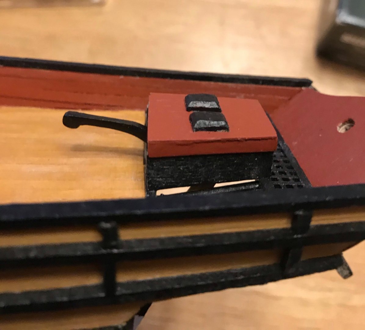
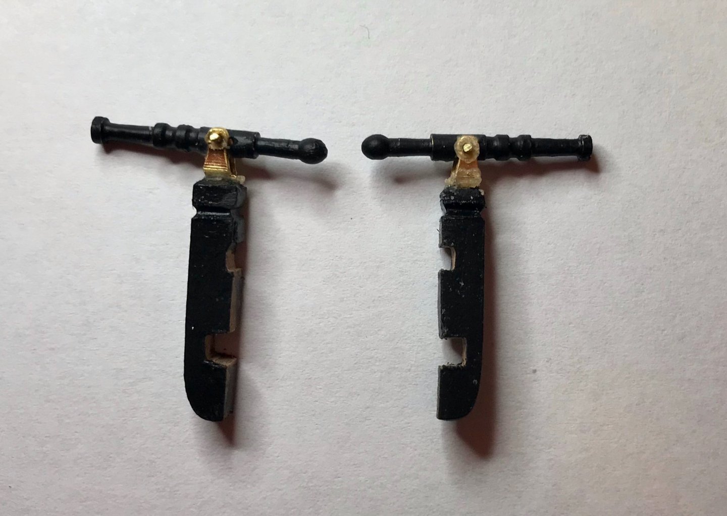
Tonight, I finished constructing the swivel guns, for which I'd been preparing things over the last several days. Things started off well, but in the end, these were a royal pain. But...they're done, except for a bit of clean up and attaching to the hull. The supports are made of 4x4 walnut. After measuring and cutting to length, I sanded a curve at the bottom. Then, I cut slots to fit the rail cap and trim piece #2 (first photo). After several test fittings, they slipped right into place (second photo). Next, the plans called for beveling between the rail cap and the gun (third photo). Then things got tough. The plans indicate that the gun mount is a single piece drilled into the top of the support. However, that isn't the case. Rather, the kit provides metal brackets that need to be fastened to the support with a pin. The guns are mounted on the bracket using a thin brass wire (somewhat less than 1mm). The brackets are curved, but unfortunately, that means the holes for the wire don't line up with the holes in the guns. So, after straightening the brackets, I put the various pieces together. This didn't go well. I lost track of how many times I knocked the bracket off the support while trying to mount the gun on it. After much longer than I anticipated, though, I managed to get everything together. During my frustration, I didn't think to take any photos, but here are a couple at the end showing the swivel guns on their supports, and then a final dry fit.
- 79 replies
-
- 2
-
-
- sergal
- sciabecco francese
- (and 1 more)
-
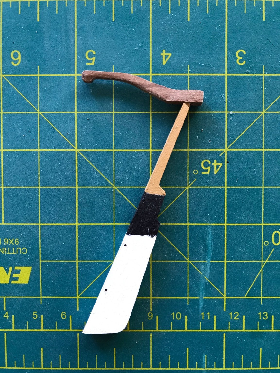
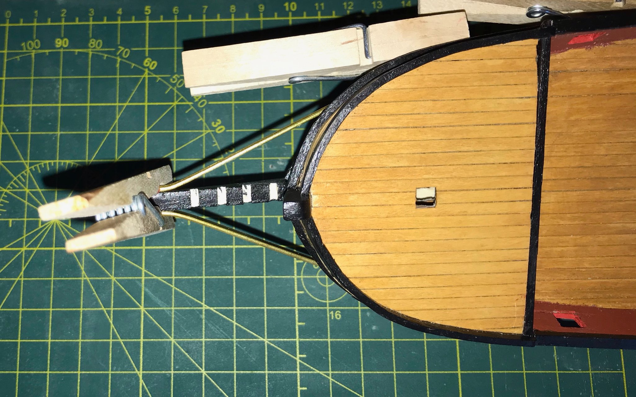
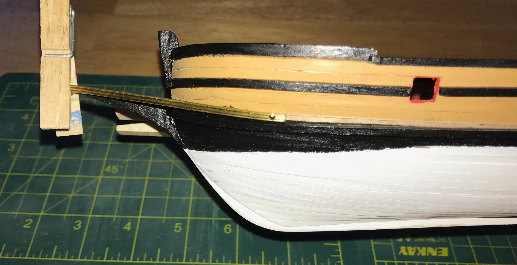
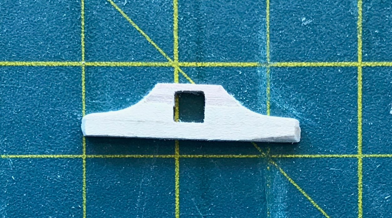
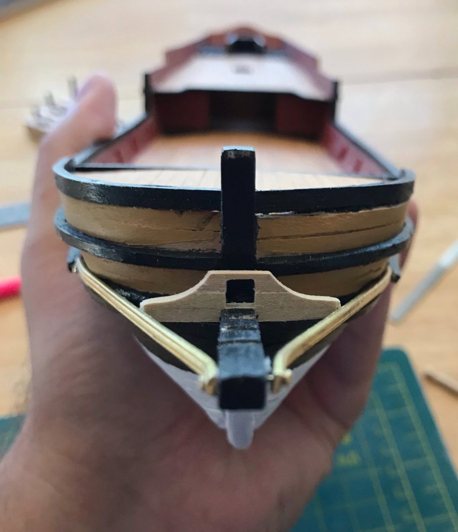
I've been able to devote quite a bit of time to the xebec over the last two days. I've also been able to work a little more quickly, since my parents and in-laws spoiled me with Christmas gifts this year—a set of clamps, a jeweler's pliers set, a precision tweezers set, miter shears, and a Dremel 4000! While my goal isn't necessarily to go fast, the miter shears and Dremel have saved me a TON of time. At this point, the end is in sight for the exterior of the ship. This post covers three things I've been working on for the past two days. First up, continuing work on the exterior trim and rail caps. The starboard side is finished (except for the swivel gun)! I'm still finishing up the port side, but that should be done tomorrow at the latest, since there's just one rail cap left to attach. Last Wednesday, I posted that I had cut out all of the pieces for this phase of the trim work. The most challenging step involved cutting lap joints into the four vertical trim pieces and horizontal trim piece #1. You'll notice that I had painted piece #1 before realizing I needed to cut lap joints; the black paint made it harder to see my lines, but I made it all work out in the end. These photos show: 1) these five trim pieces after I had glued them together, 2) dry fitting those pieces, and 3) the starboard superstructure with all trim pieces and rail caps installed (except the swivel gun). 1) 2) 3) Next, continuing work on the head. As I mentioned in the previous post, the gammon piece is a particular problem here, since there's a typo in the plans. In the end, I glued together four planks to make the gammon pieces. The base is 2x2 limewood. On top of that are two shorter pieces of 2x2 limewood, positioned with a 4mm gap for the bowsprit. And finally, the top piece is 3x2 limewood, with a 2x4 window cut out for the bowsprit. The photos show: 1) After gluing and clamping them together, I roughed out the shape; 2) using the Dremel and a file, I cut out the curve; 3 and 4) dry fitting the gammon piece, with and without the bowsprit; 5 and 6) forward and overhead shots of the completed head; and, because I was on a roll, 7 and 😎 side and overhead shots of the head assembly with the bowsprit. 1) 2) 3) 4) 5) 6) 7) 😎 Finally, continuing the theme of "one thing leads to another"... I've been wrapping my mind around the trim on the upper transom (which will be the third and final phase of exterior trim work). One issue is that I'm pretty certain that the pre-cut hole for the sternsprit is in the wrong spot. In order to confirm this, I cut and shaped the sternsprit. But before I can dry fit it and find the correct spot for the hole, I need to build the dividing wall between the aftdeck and the rudder well assembly (the sternsprit is mounted into that dividing wall). But before I can build the dividing wall, I need to build and attach the rudder. Thankfully, the rudder is pre-cut, so that's no problem. However, the tiller needed to be fabricated. This was a new challenge for me, since in all of my previous kits, the tiller was pre-cut. After taking measurements from the plans and reducing them accordingly, I glued and clamped two planks of 4x4 walnut in offset position. After tracing out the shape, I used the Dremel to rough out the tiller, a file to get the final shape, and an emery board to smooth everything out. I still need to cut the slot for the rudder, but I'm pleased with how it turned out. I didn't think to take pictures of the process, so just one shot of the shaped tiller. There is some shaping in the vertical dimension, too, but I couldn't get a decent photo to show that. Where the tiller connects to the rudder, it's 4mm wide; then there is a short transition zone and the full length of the handle is 2mm wide.


- 79 replies
-
- 1
-
-
- sergal
- sciabecco francese
- (and 1 more)
-
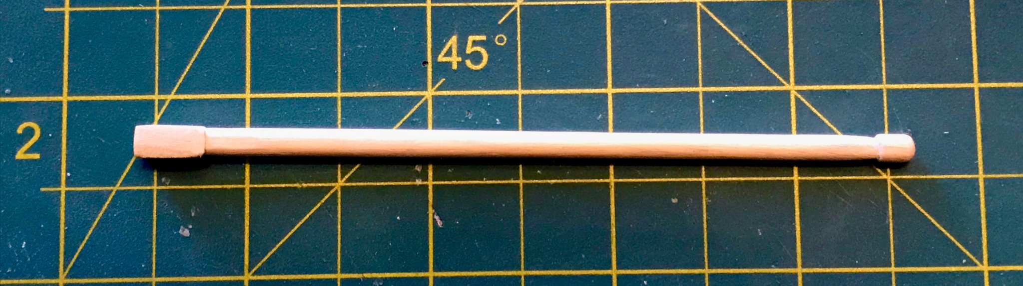
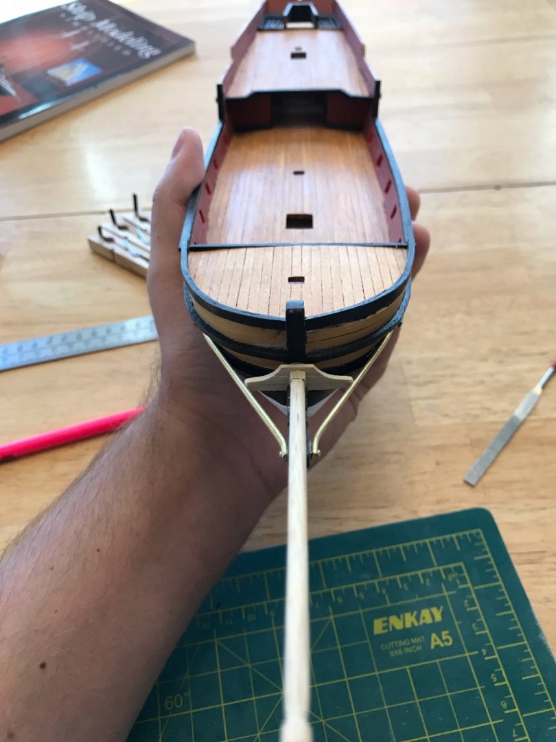
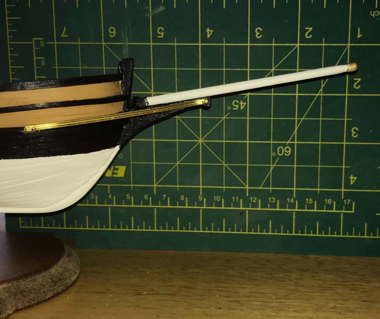
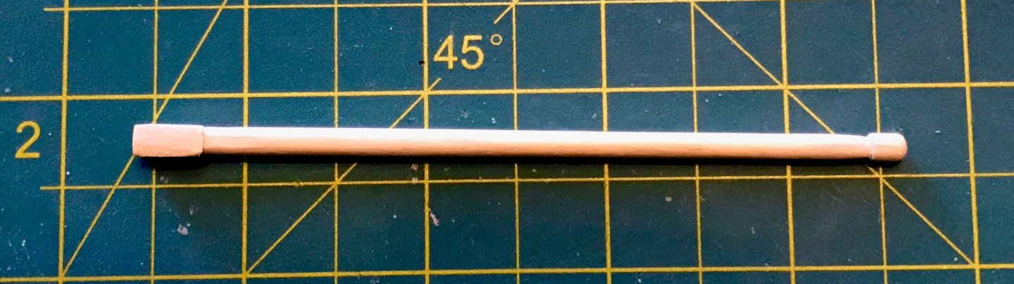
Well, as they say, one thing leads to another... I finished painting the two horizontal trim pieces #5 and was ready to think about attaching them. But since they abut the head rails, I needed to make sure I knew exactly where that joint would be. But since I couldn't seem to get the head rails to stay in place during a dry fit, I needed to attach them. But before I could attach them, I needed to work out the plan for the crosspieces on the head. But before I could do that, I needed to be sure I knew how they would fit with the bowsprit. All this to say, I spent Christmas morning, prior to our pandemic-imposed family video conference/Christmas celebration, making a bowsprit and working my way backward through the steps in the first paragraph. This bowsprits a bit different than the bowsprits on my other kits, which were just simple tapered spars. This one has a square bottom and a bulb on the end, with a slight taper from 4mm to 3mm. The square bottom was good practice for the masts, since I had to build it out of 2x6x10 pieces attached to a 4mm dowel. Needless to say, I had a lot of sanding to do! I rounded the top of the bulb and seem to have a couple choices, since different photos of the kit show different things. Either, I'll paint the bulb with a gold/brass paint (I'm using Admiralty paints from Caldercraft) or I'll apply a ring of brass strip left over from a previous kit. Not sure yet, but I'm going to wait on that decision for awhile. One thing that became clear is a typo in the plans. The widest cross piece in the head assembly (I think this would be the gammon piece?) is indicated as being made from two pieces of 2x3 limewood, with the bottom one recessed into the head and with a square hole cut to fit the bottom of the bowsprit. But I just don't see how that will be possible, unless I sand the square bottom pieces down to nothing.. My plan is to use 2x3 for the bottom half and 2x6 for the top...I think I'll have enough of the 2x6 planks to do that, at least! As for the placement of the crosspieces...that was a little tricky to figure out. The front three pieces will be 2x2 limewood, recessed into the head. I ended up using a very thin plank to measure the length of the head, which turned out to be 2/3 the size of the detail picture in the drawings. After some more measurements and a little math, I decided to mark them out with 5mm gaps. After drawing them on the thin plank, I transferred them on to the head and cut them out. You can see them in the next photo, after I had painted and attached the head rails. The second photo here is a shot of the port head rail clipped in place as the glue dries. Both headrails have rivets made of pins. For me, the headrails are the first big symptom of a problem that I thought I had fixed. When I first started, the plywood sheet with the keel/stem post/stern post was significantly curved. I thought I had remedied that, but as I soon as I dry fit the headrails for the first time, I discovered that they will not and cannot be symmetrical on my ship. There is still a slight curve, so slight that I hadn't noticed it so clearly until now, but significant enough that the two headrails fit a little differently from each other. (Note: The head fades a bit to port, but not as much as it appears to in the overhead shot above; the camera angle and crooked clothespin are exaggerating it there.) Regardless, with the head rails attached, I glued the starboard trim piece #5 into place. Since this sits directly on top of the 2x2 plank that comprises trim piece #6, clamping was an interesting challenge. You can see my solution in this photo (the clip on the head rails was removed shortly after the photo; the glue was dry, so it isn't needed anymore). I'll add the port piece tomorrow and once I do that, I will finally feel ready to mount the ship on the stand!


- 79 replies
-
- 2
-
-
- sergal
- sciabecco francese
- (and 1 more)
-
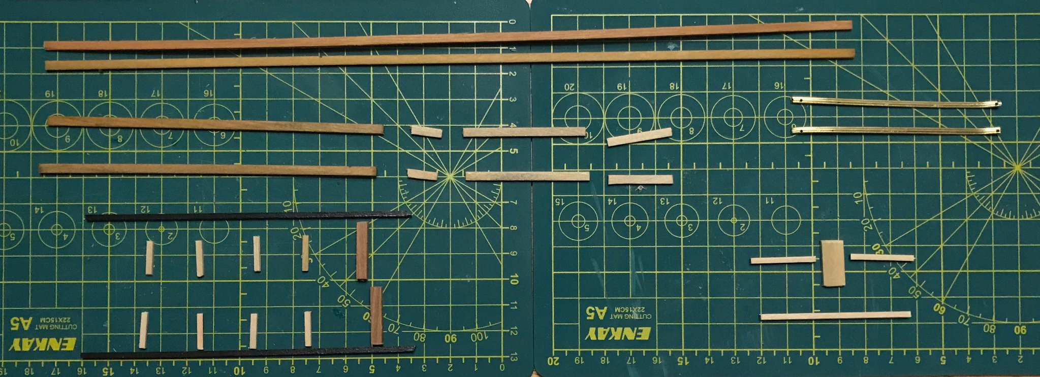
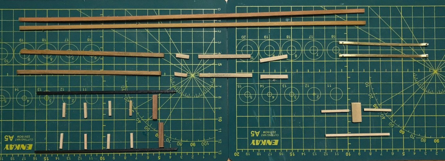
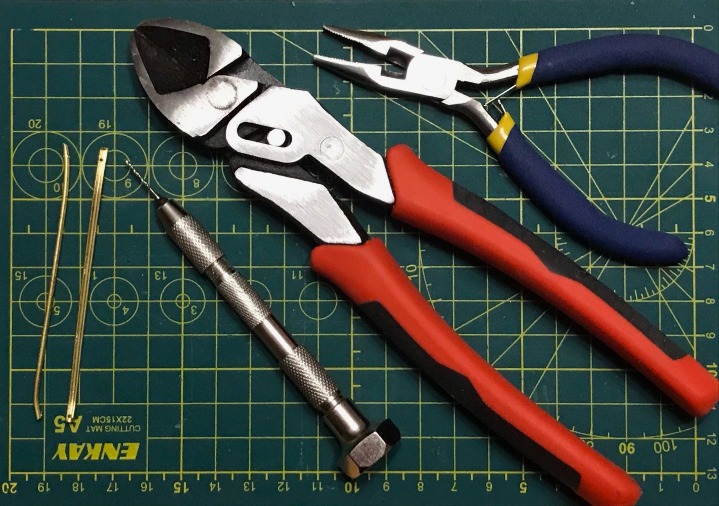
Over the last couple days, I've been sanding down the pieces of trim that I mentioned in the last two posts. Smoothing out the joint where trim piece #3 connects to the midship rail caps, smoothing out the joints where side trim pieces connect with transom trim pieces, and removing the excess at the ends. As a result, there's plenty of touch-up painting to do, but otherwise I'm satisfied with that work for now. This evening, I launched into the next phase of trim work . For now, this just consists of measuring and cutting pieces. The photo shows all of the pieces for this phase. At the top are the two planks for trim piece #5; they're wet because I was soaking them in hopes I could straighten them out enough for the job (the one on top is out of shape, since it was one of the pieces that I unsuccessfully tried to shape for the midships and bow rails). Those two planks will abut the head rails, the brass pieces in the upper right-hand corner. The next tier down are the eight remaining pieces of the rail caps. In the lower left-hand corner are trim pieces #1 (the long ones painted black), the vertical trim pieces (2x2 limewood), and the brackets for the swivel guns (4x4 walnut). In the lower right-hand corner are the trim pieces for the upper transom. There will be a third phase of trim work that will focus on the edges of the upper transom, but I'm not yet ready to tackle that problem. The two head rails have concerned me for a while. In my previous kits, I've worked with .6mm-thick brass strips, which were easy enough to cut and shape with the low-tech hand tools that I have available. However, since the brass strip in this kit is 2mm thick, I wasn't sure my tools would be sufficient. Thankfully, I was wrong...though the job would have been easier with power tools. The photo shows the rails and the key tools I used. After marking the center point with my Exacto knife, I used my sturdier wire cutters. After filing the ends to smooth them out a bit (probably still need to do more of that), I used the flat part of my needlenose pliers to bend 5mm on the end that will attach to the head. Essentially, I held the brass strip firmly with the pliers, then bent it by hand at the edge of the pliers. Once the forward end was bent correctly, I used a dry erase marker to indicate where the brass strips made contact with the hull. Then, I again used the needlenose pliers to shape the brass to follow the hull's curve (in the photo, the rail on the left is turned on its side to show the curve). Finally, I needed to drill rivet holes. A drill press would have made very quick work of this...unfortunately, I don't have one. But with patience and a brand new 1mm bit, I got the job done with my pin vise drill! I just wish I had managed to keep the holes centered a little more consistently! Next step: sanding and shaping the various trim pieces, paying particular attention to preparing lap joints where needed.
-
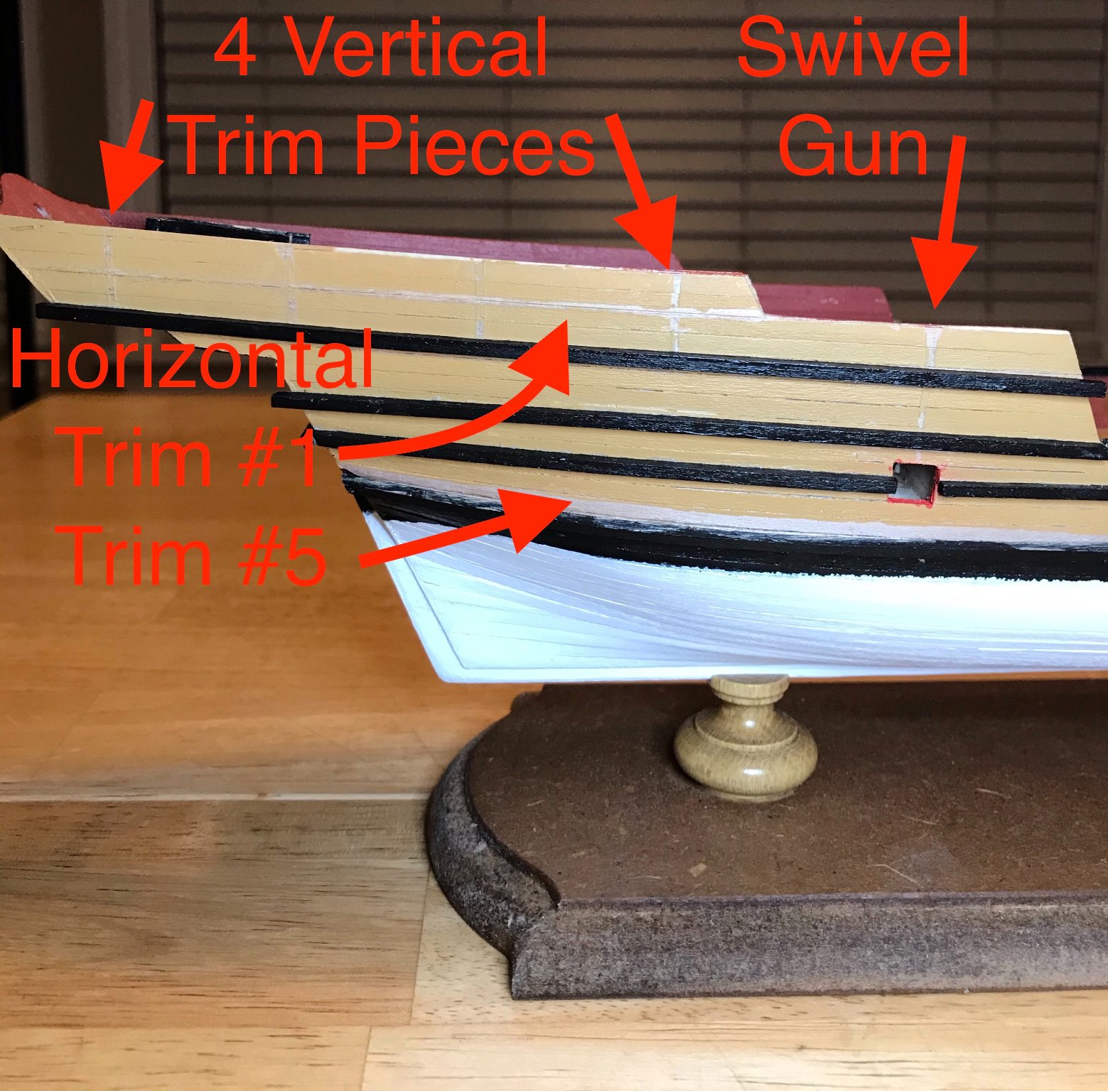
As planned, this morning I finished painting the last piece of trim for this stage of working on the hull. This evening, I started attaching them. I've been picturing the "bumblebee" design for a while, but it's nice to see it starting to come out! There's still a fair amount of clean-up work to do, but that will be work for another day. First, a couple overview shots after attaching most pieces shown at the end of my last post. Regarding the note in the second photo: while installing the port bow rail, I accidentally put too much pressure on trim piece #6, dislodging one section of it. I'm not overly worried...trim piece #5 abuts that piece and so I can realign it then and give it more support. From above, you can see 10 of the pieces that I installed yesterday evening and today: the two bow rails, the after edge of the foredeck, the midship rail caps, and the five pieces that line the forward edge of the aftdeck. While there's still quite a bit of trim work to do on the upper transom, the sides are nearly done. This last photo is a detail shot with annotations of the pieces that remain (not including the rail caps). I was about to attach the horizontal trim piece #1 when I realized I would need to do some lap joints with the vertical pieces. The swivel gun will have lap joints, too, but since it's mounted on a piece of 4x4 walnut and the trim pieces are 2x2, that won't be a problem.


- 79 replies
-
- 1
-
-
- sergal
- sciabecco francese
- (and 1 more)
-
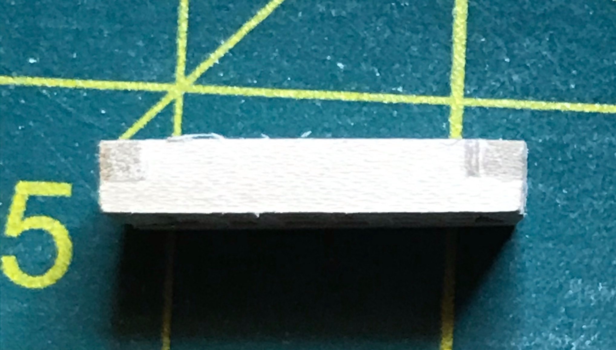
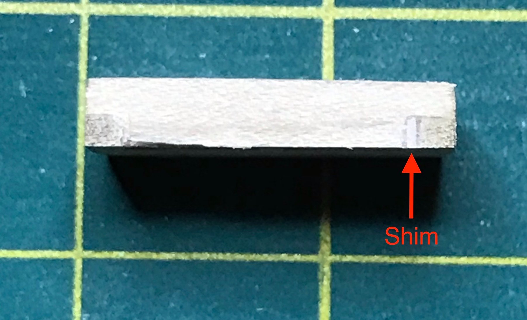
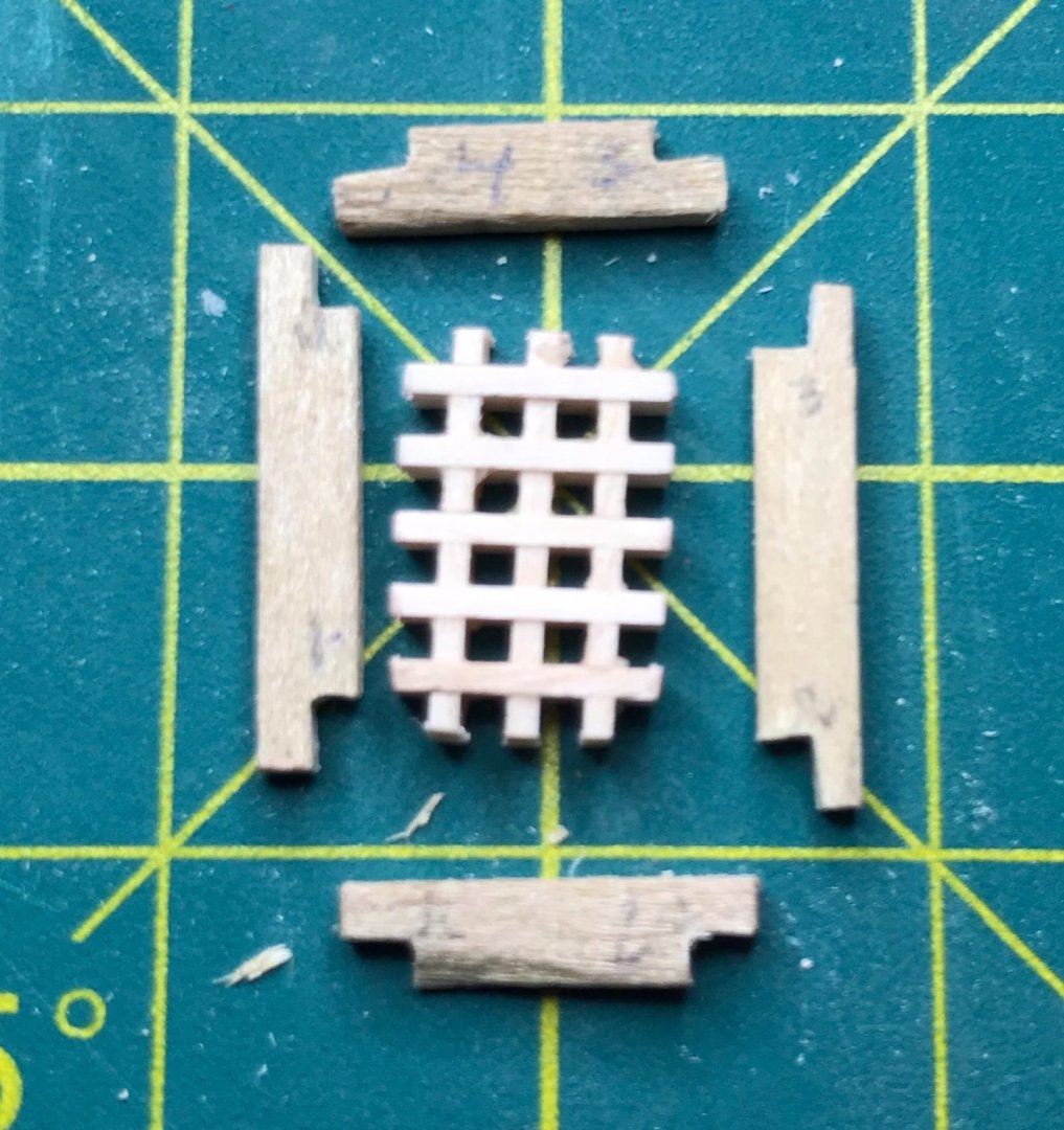
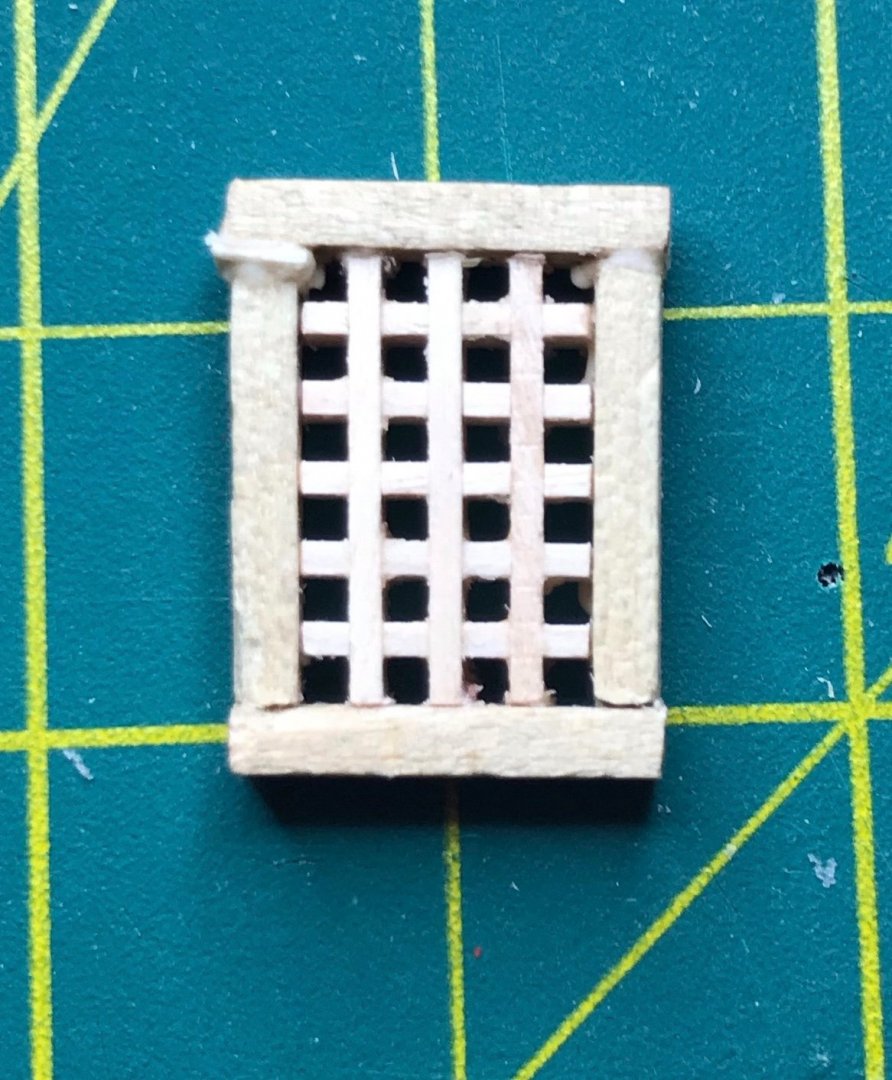
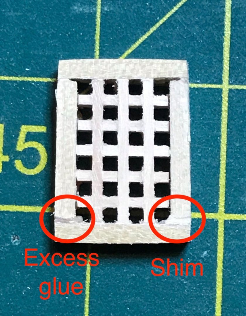
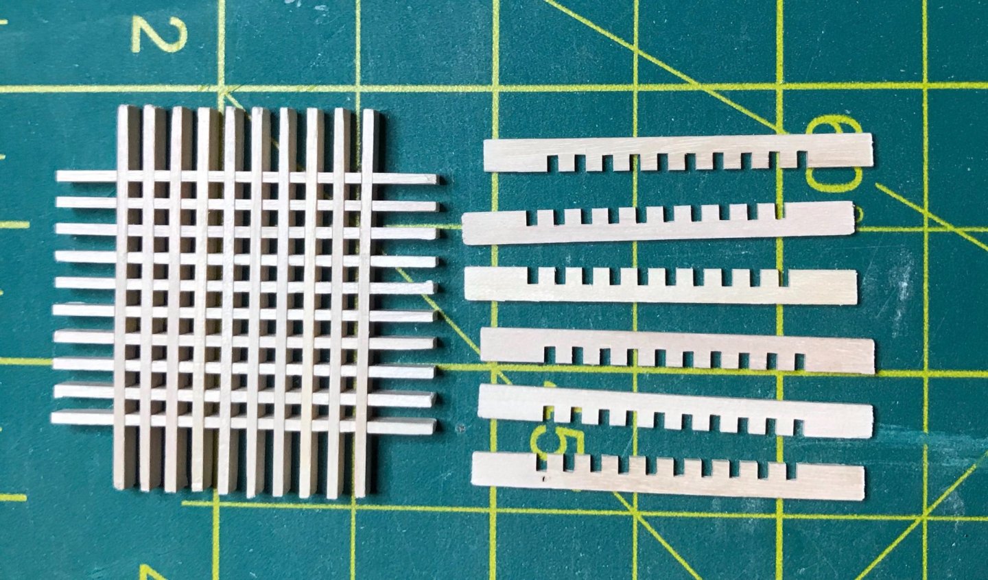
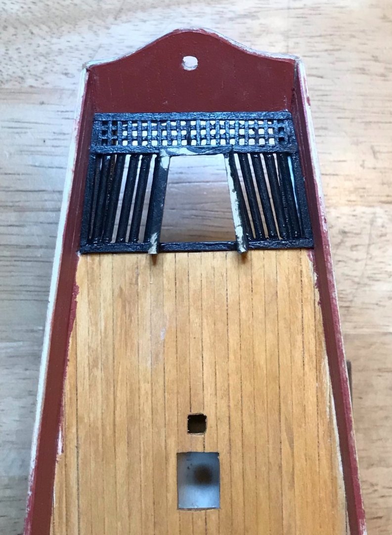
Once again, I decided to work ahead a bit while waiting for coats of paint to dry. This time, I focused on the aft hatch cover. After doing the grating for the midships hatch cover and the rudder well assembly, I approached this with a lot of confidence. Of course, this is not to say it went perfectly, though I'm very pleased with how it ended up. I began by assembling the grating...which took more tries than it should have to cut pieces the right length. After gluing and then sanding, I was ready to attach the frame. I was still feeling ambitious, so decided to do lap joints at the corners. After cutting the four frame pieces, I measured and trimmed off the corners. Next, I numbered each joint, so I could file them down to fit (first photo). This step went pretty well...except for one spot in which I must have been a little overzealous with the file. However, I made a shim out of .6mm-thick limewood and it was the perfect thickness (second photo, with the shim in the upper left). Finally, it was time to sand and clean everything up. When I took the first of these photos, I noticed that I had a bit of excess glue in one corner and the shim wasn't as perfectly lined up as I thought. Thankfully, using the tip of my Exacto knife and a straight pin, I could clean those up. The second and third photos show the lap joints, with the shim indicated in the third. I still feel like a novice in a lot of ways, but feel pretty good about how these turned out! At the very least, they turned out much better than the 45 degree joints on the midships hatch cover. (I'm eyeing a pair of miter shears as a possible solution to help me cut angles more accurately and consistently.) One nice thing about this kit is that the quantity of grating stock is far more generous than the rest of the wood stock. I still have this much left, even after making two hatch covers and the rudder well assembly—and ruining more than a few pieces along the way! As for the next step, it will finally be time to attach the trim pieces I've been working on! In the morning, I'll finish painting the piece that goes on the after edge of the foredeck. Once that dries, I can attach the pieces laid out here (from left to right): the three pieces for the lower transom, three horizontal pieces for each side of the superstructure, the midships rail caps, and the rail pieces for the bow. In addition, there are two small pieces that are not pictured that will finish the trim on the forward edge of the aftdeck (you might be able to make out the three pieces that run athwartships there; the remaining two run diagonally to connect those three).


- 79 replies
-
- 1
-
-
- sergal
- sciabecco francese
- (and 1 more)
-
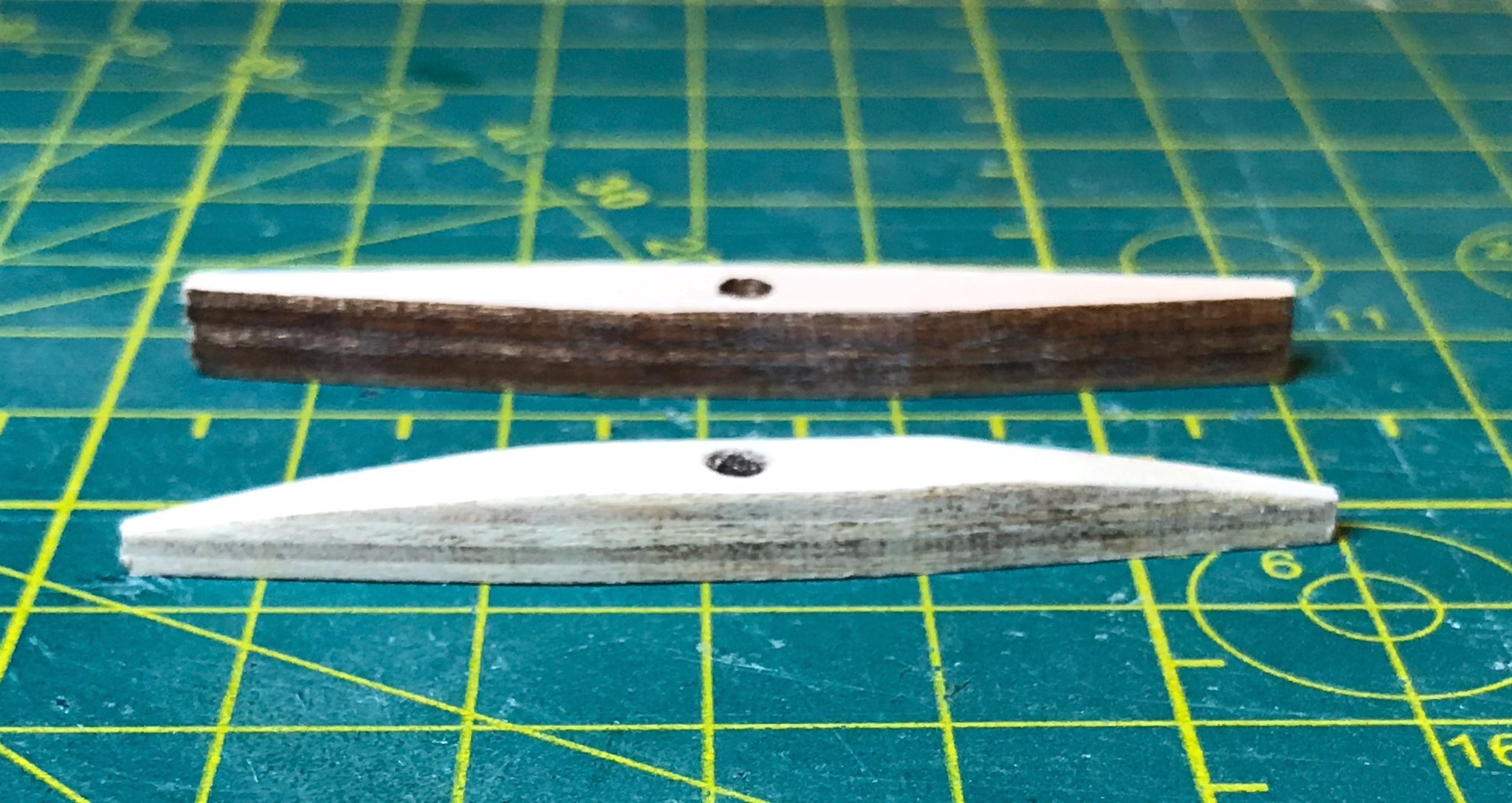
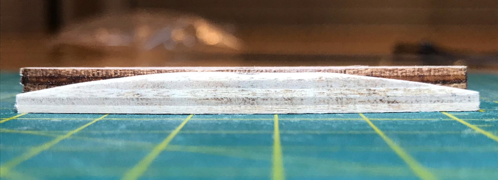
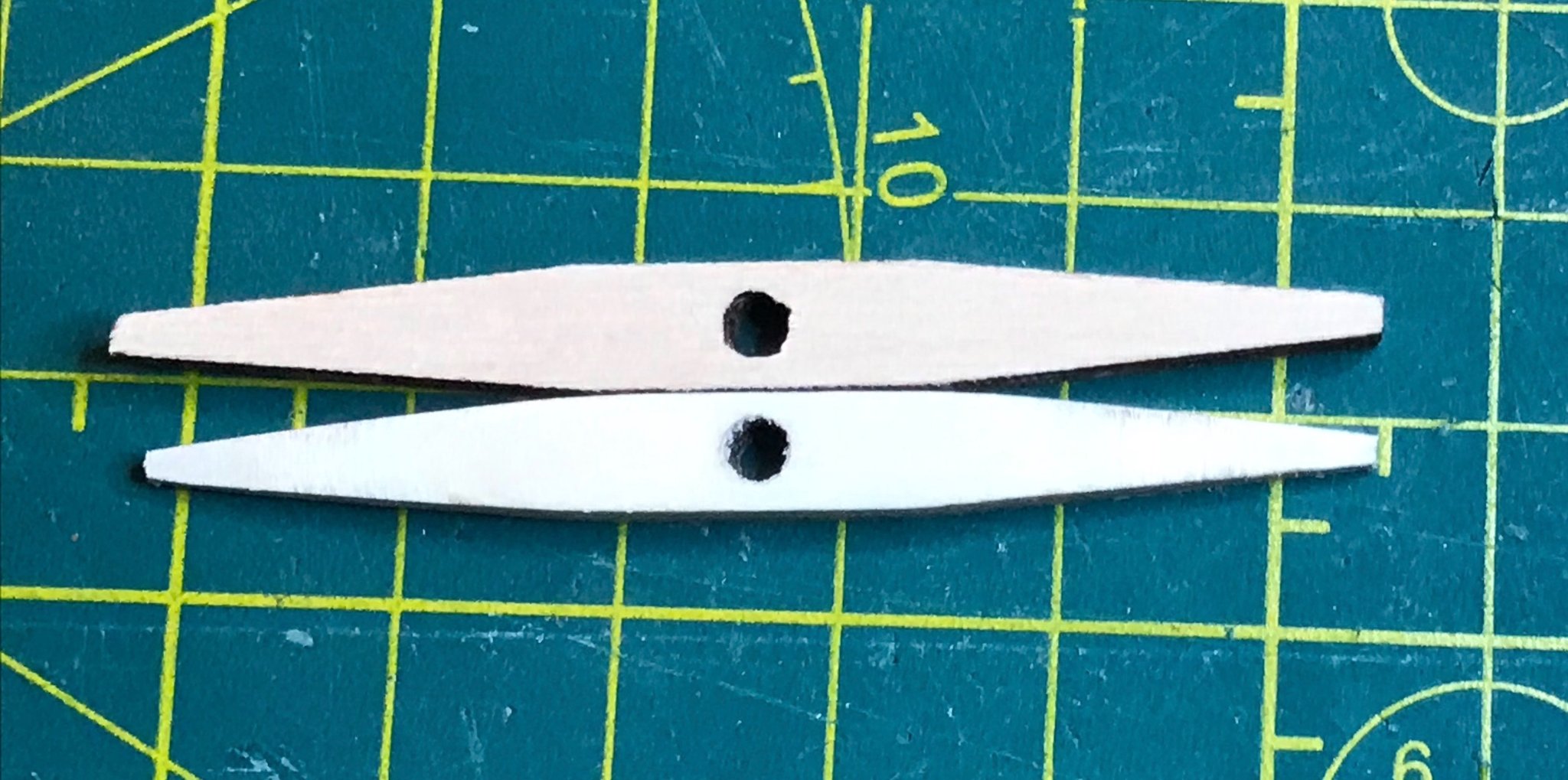
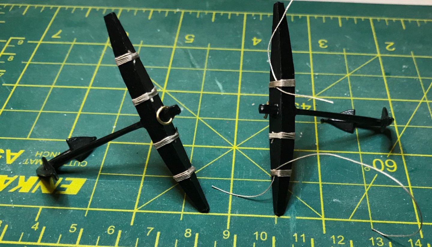
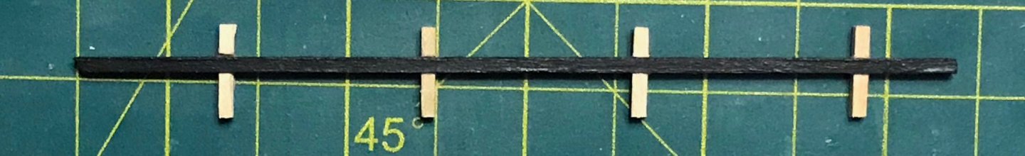
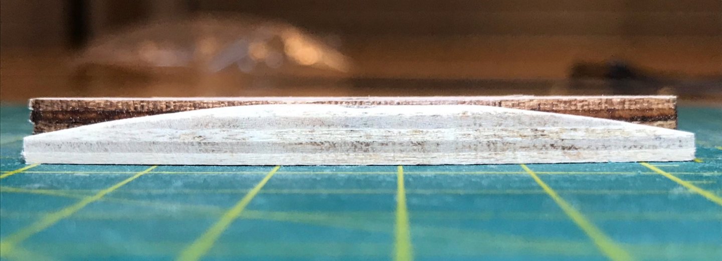
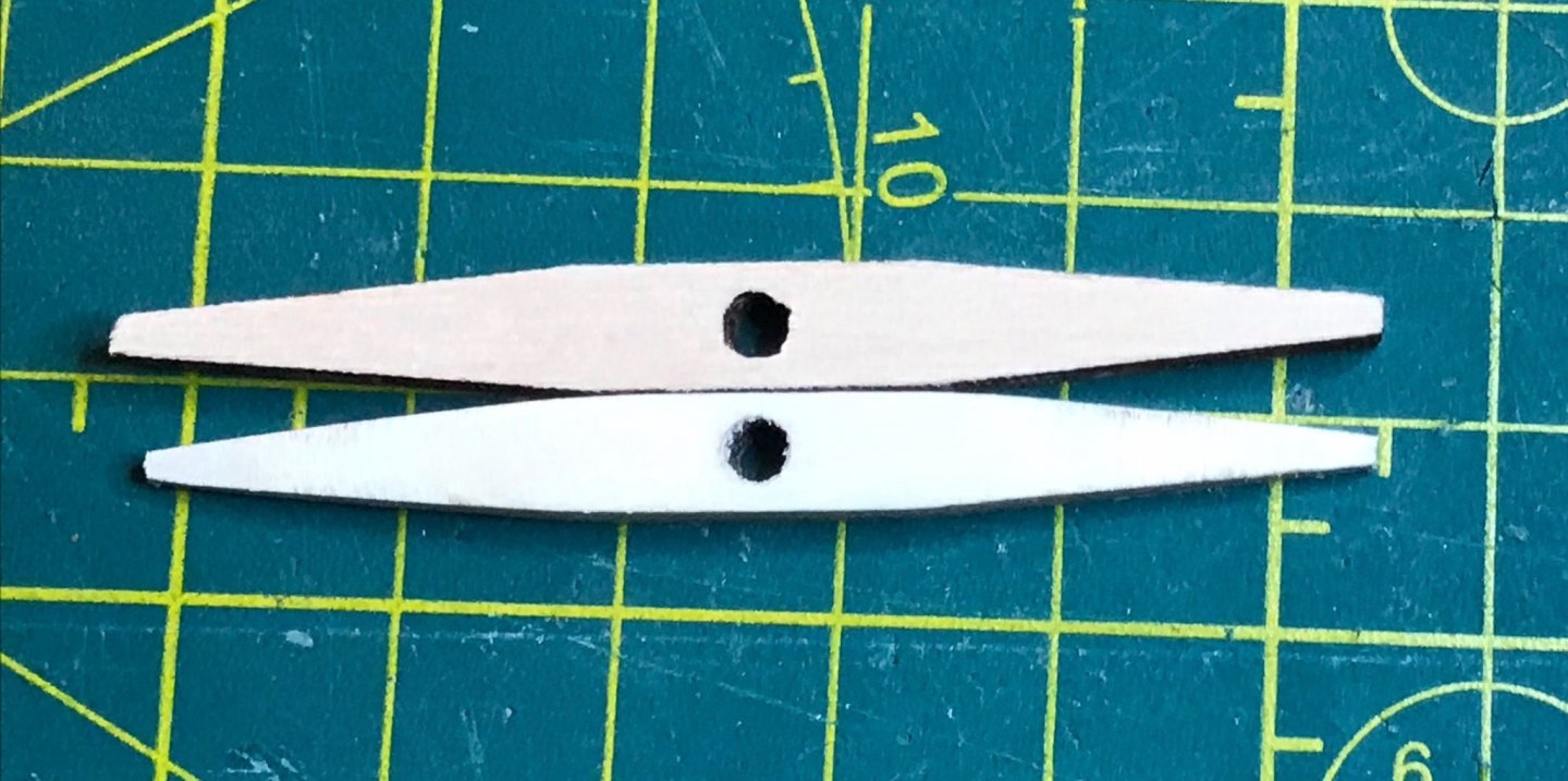
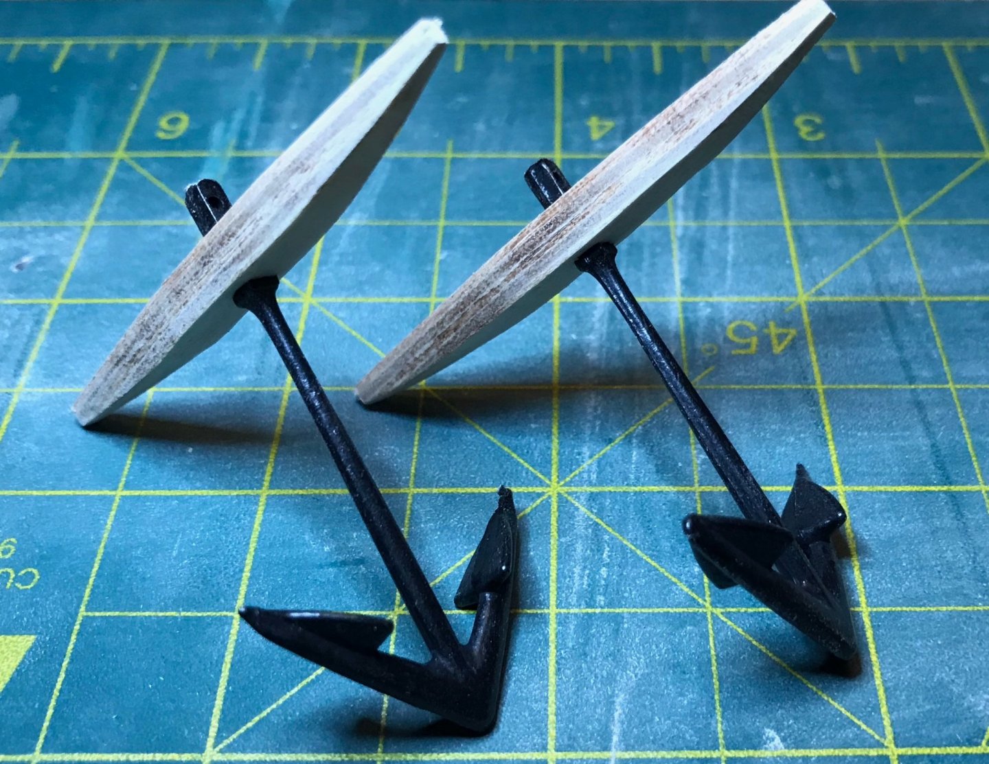
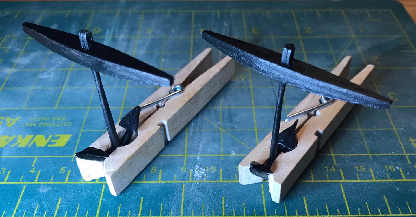
I've been continuing to work on preparing trim pieces—"only" 24 more pieces of trim left to attach! I've also been working on shaping the rail caps (a term I just learned...I've been incorrectly calling them gunwales in previous posts). That has been a frustrating process. The two longest pieces, which are amidships, are 2x3 limewood that need to be edge set with a gentle curve. I've tried bending them twice, but so far they just spring right back into their original straight shape. Tonight I soaked them in hot water, then pinned them into the after part of the jig I wrote about on December 6. I'll leave them like that for a couple days and see if it gets me the curve I need. I've also painted and installed the rudder well assembly. These extreme close-ups and my ring light really emphasize the imperfection of my paint job...though the top of the housing is intentionally unpainted, so the cover can eventually be glued on there. It looks better in person, though there's clearly a lot of room for my painting skills to improve. The light-colored bit toward the right side looks like unpainted wood, but is actually a bit of excess glue that I couldn't reach to wipe it away. Once it dries, I'll use my Exacto knife to clean that up. Apart from that, I'm pleased. The photos are two shots of the counterstern from above, one with the rudder well cover and one without; then one from below. Finally, in between coats of paint on trim pieces, I've been working on the anchors. Curiously, the plans call for fabricating the anchor stocks out of 4x4 walnut, even though the plywood sheets in the kit include two pre-shaped anchor stocks. To preserve my wood supplies, I went ahead and used the plywood pieces. The first three photos were taken after shaping the first stock. In the overhead shot, you'll notice that I didn't have to do much in the horizontal dimension; I sanded down the ends so they were less pointy, but otherwise that was good. In the side shot, you can see that most of the work was focused on the vertical dimension. The center portion is to be 4mm tall, while the ends taper down to 2mm; when I took the photo, I hadn't quite finished with the center section. Finally, the high angle shot gives a little better perspective on the overall shaping. The pre-drilled holes are perfectly sized to fit onto the shank. The shanks and flukes come as a single die-cast metal piece, finished in black. There were a couple nubs from the casting process that had to be filed off, but overall, they're made much better than the brass decorations that I'm ignoring. Two shots of the anchors with stocks attached, then with the paint drying on the stocks. Once the paint is dry, I'll put on some finish, then attach the rings. After that, I'll set them aside until I've finished with the hull trim and rail caps.


- 79 replies
-
- 1
-
-
- sergal
- sciabecco francese
- (and 1 more)
-
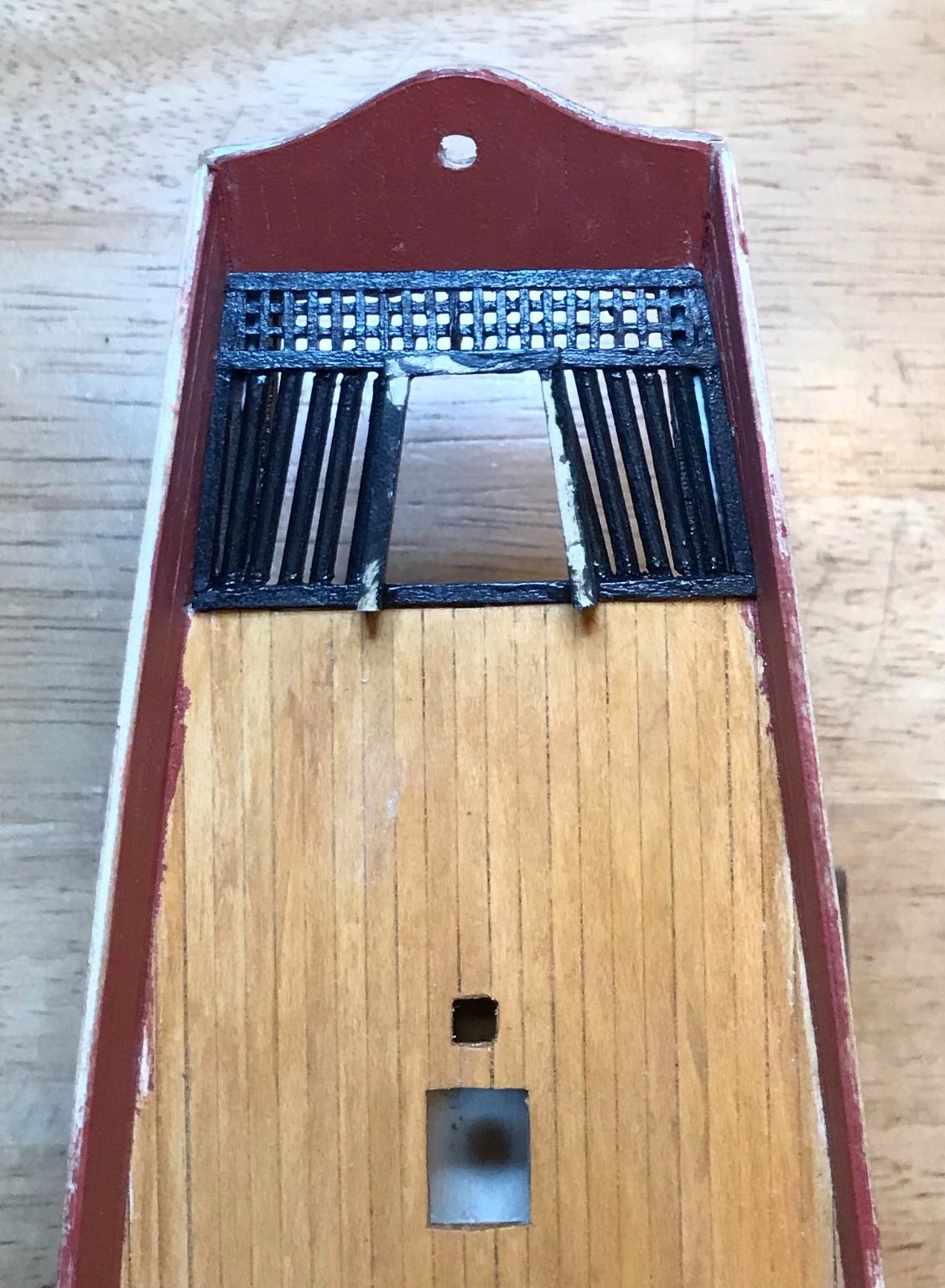
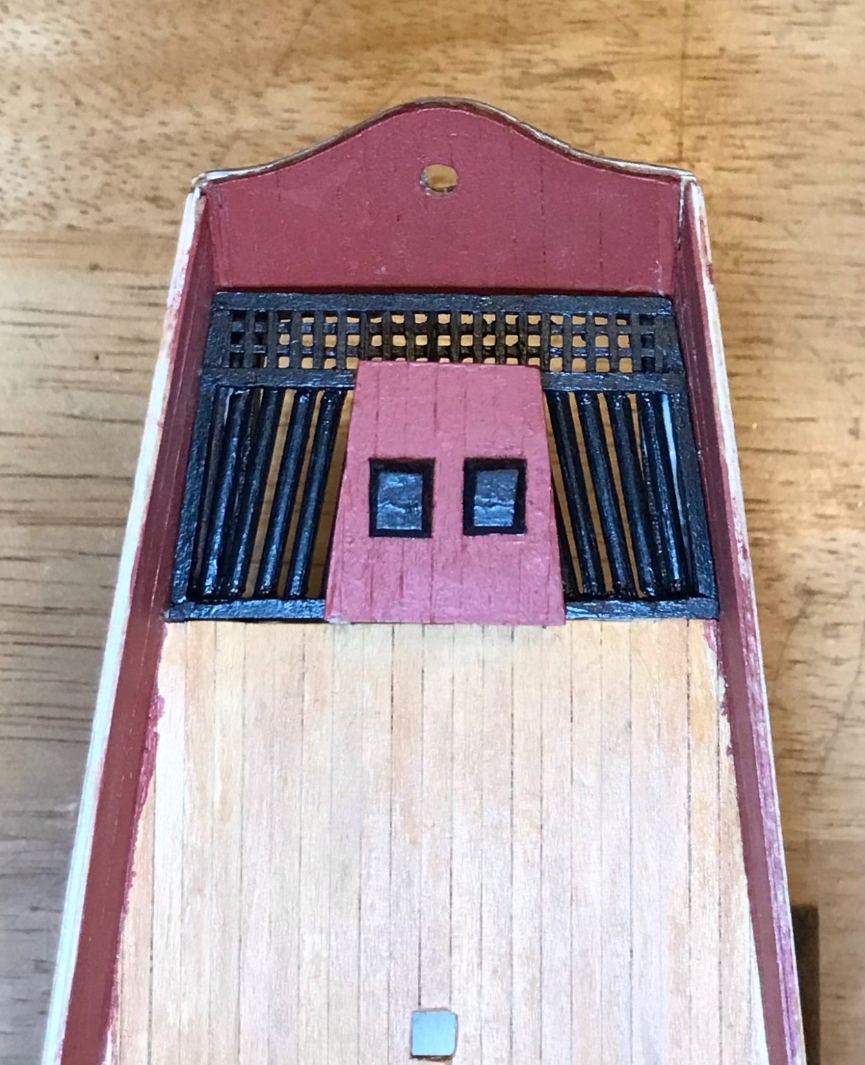
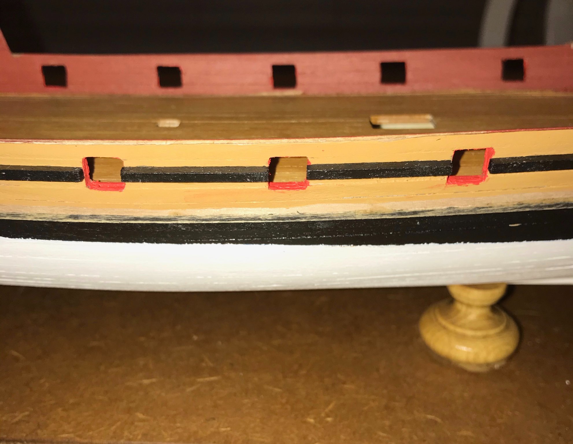
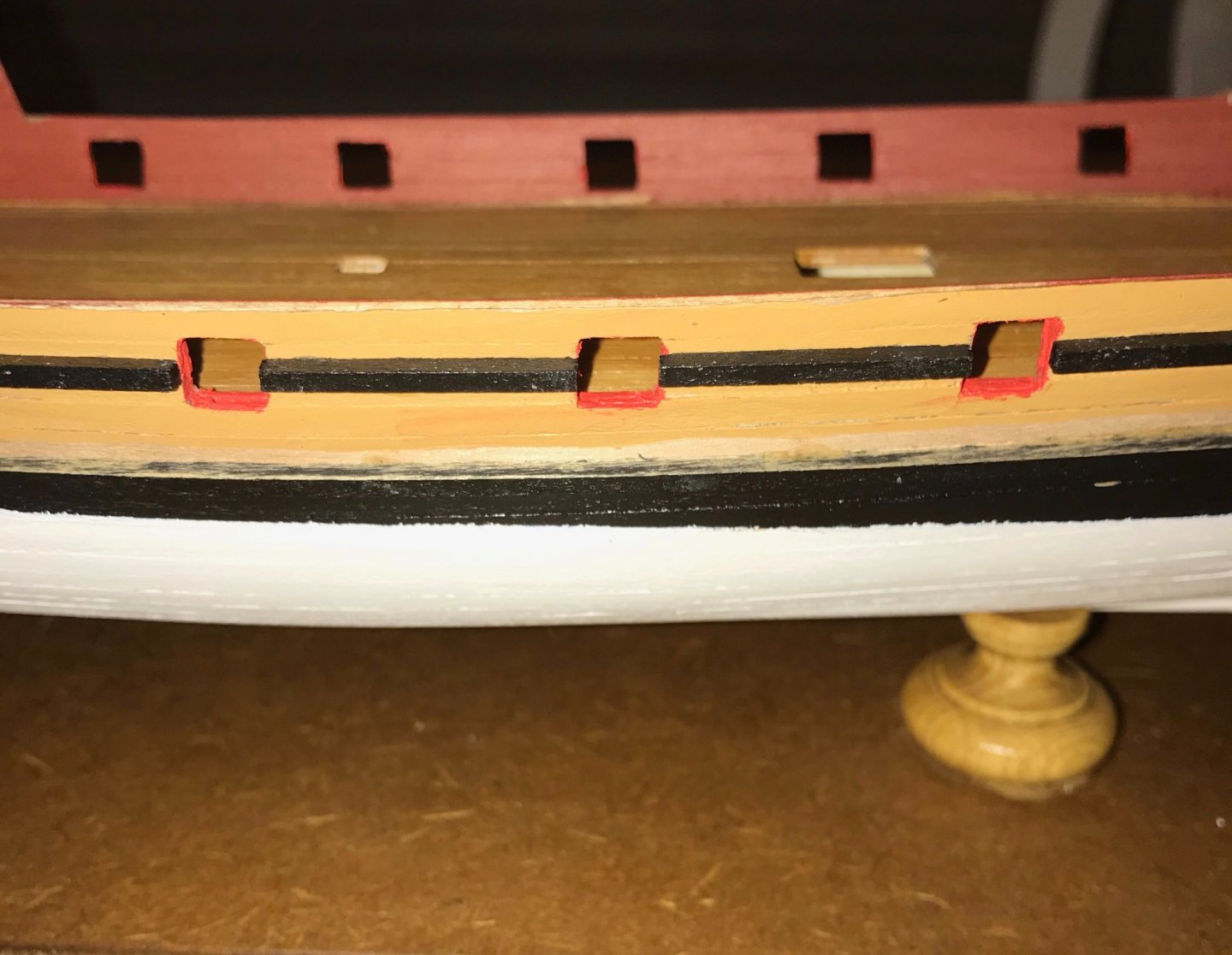
A short update after the very long one that precedes this. I'm continuing to work on the exterior trim of the hull. As I posted a while back, there are six horizontal pieces of trim. I just took the clips off of piece #4 and am pretty pleased about how it turned out. This one poses a different challenge than the others, since it is aligned with the gun ports. I had two options, as far as I could tell. Either attach a single 2x2 batten and trim out the bits crossing the gun ports or measure each segment and cut the batten to measure. Because I'm painting each trim piece before attaching it, I opted for the latter. I had already attached the bow segment (seg. A), since I bent that into shape a week or two ago. But segments B through G went on pretty well. Segment G (the sternmost piece) has just a slight twist to it, so I had to hold that one in place for quite awhile before the PVA glue set. Photos are of the starboard side, with the close-up aligned with gunport #3. Especially in the close-up, you'll notice the unpainted spot where the topside of trim piece #6 meets the hull. Well, the hull's unpainted there...I got ahead of myself on trim piece #6 and had to sand off some paint after the first coat. Sometime very soon I'm going to have to solve the problem of trim piece #5. All of the other trim pieces are 2x2 battens, but #5 is 2x3. It forms a ledge that sits directly on top of trim piece #6. It also abuts the brass supports for the ram. The problem is that I need to figure out how best to cut a piece of 2x3 brass. Once its cut, I'll need to shape the two halves, so I know exactly where piece #5 ends. For those following, I'd appreciate any recommendations on cutting and shaping 2mm-thick brass. The only brass strips I've worked with before were .5mm thick and so easily handled with my wire snips and just as easily shaped with my fingers or the butt-end of my Exacto knife. Finally, I also took a little time to start working on interior trim. Some of the interior trim needs to fit into the gunwales, so I figured I might as well do some now, starting with the entry to the cabin. I lined each jamb with two pieces of 1x3 limewood. The plans call for 2x2 pieces along the base of the bulkhead. I didn't like the squared-off look there, so I rounded the exposed edge and ends. I need to go back with a little touch-up paint, but will wait to do that until I've installed the head jamb.

- 79 replies
-
- 1
-
-
- sergal
- sciabecco francese
- (and 1 more)
-
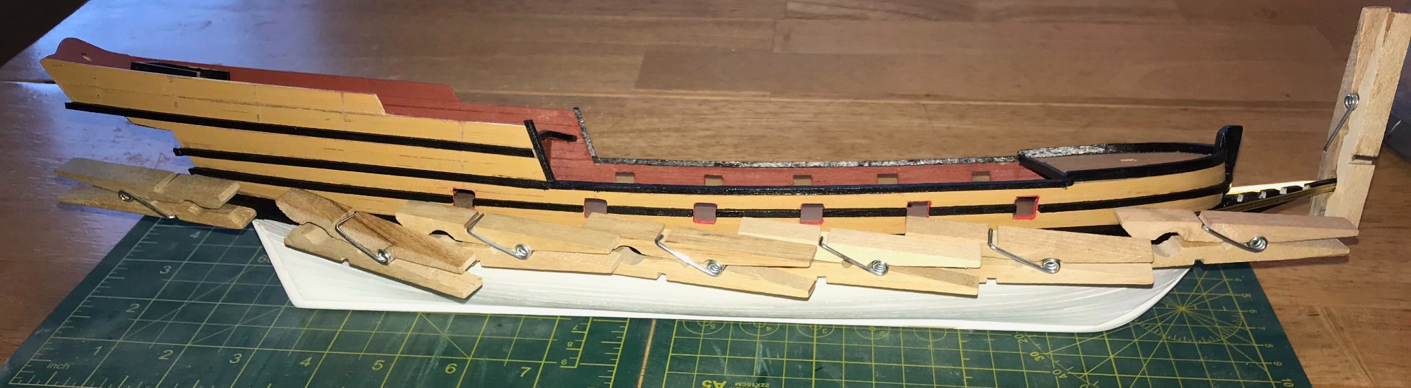
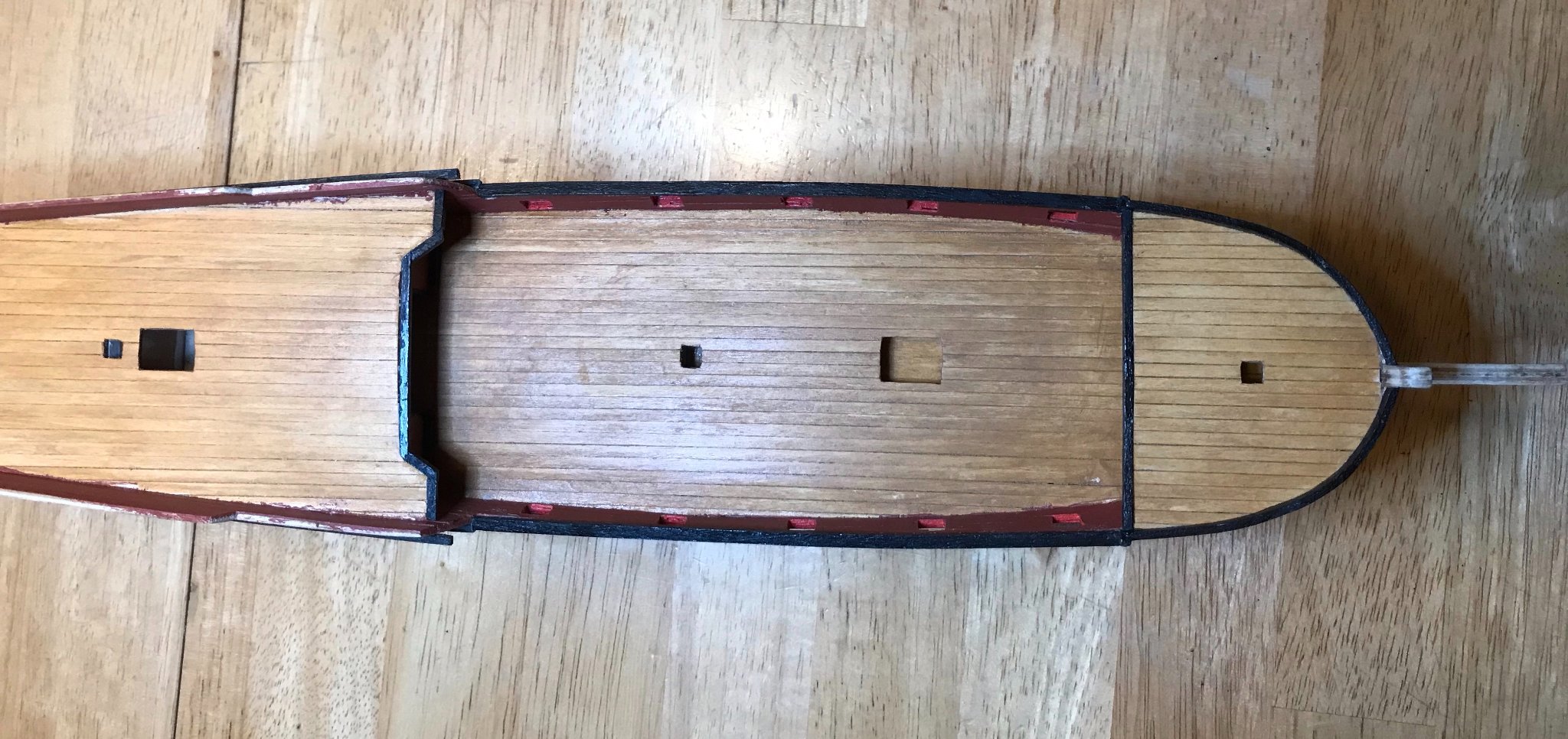
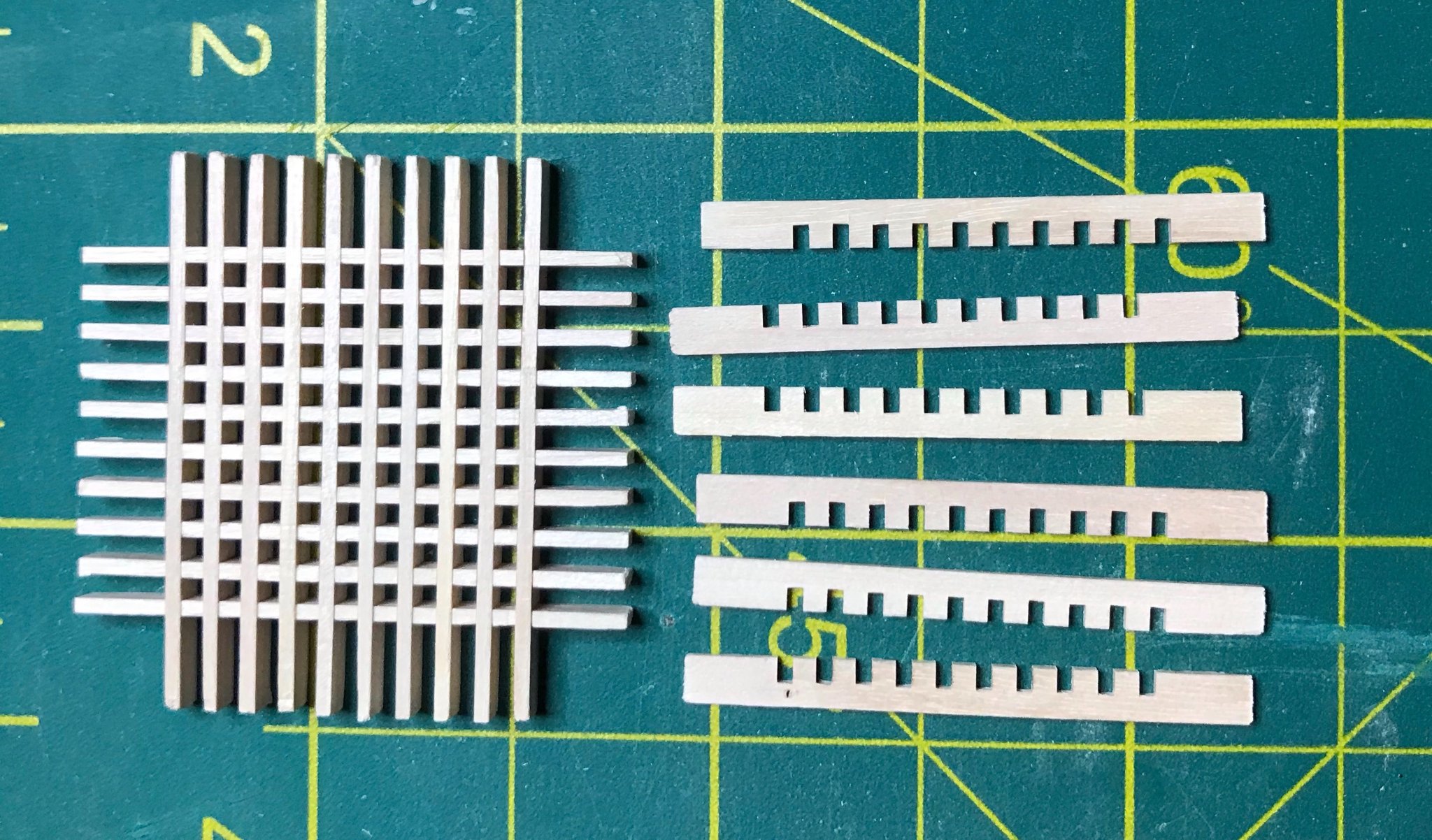
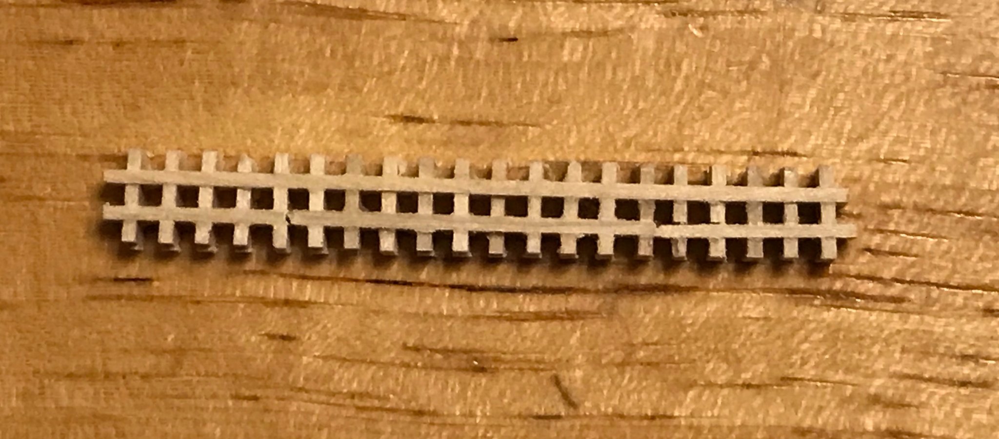
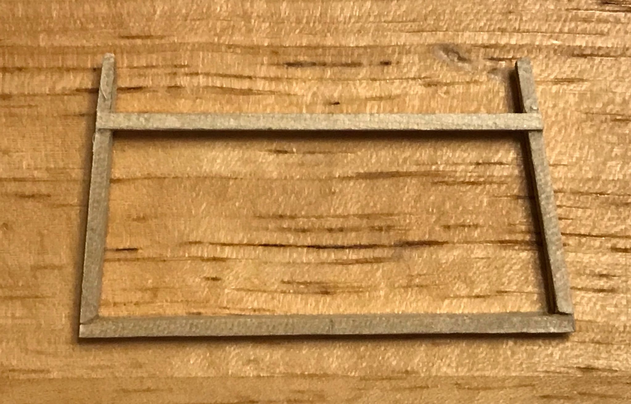
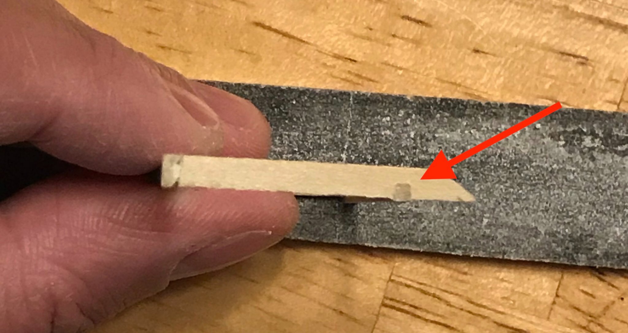
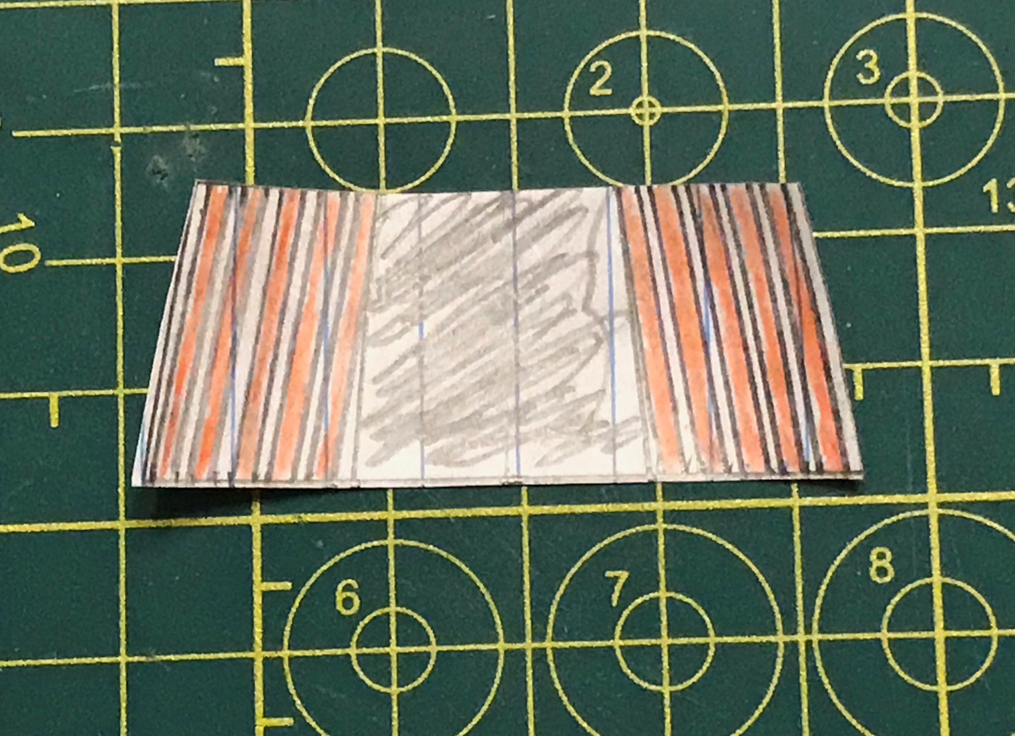
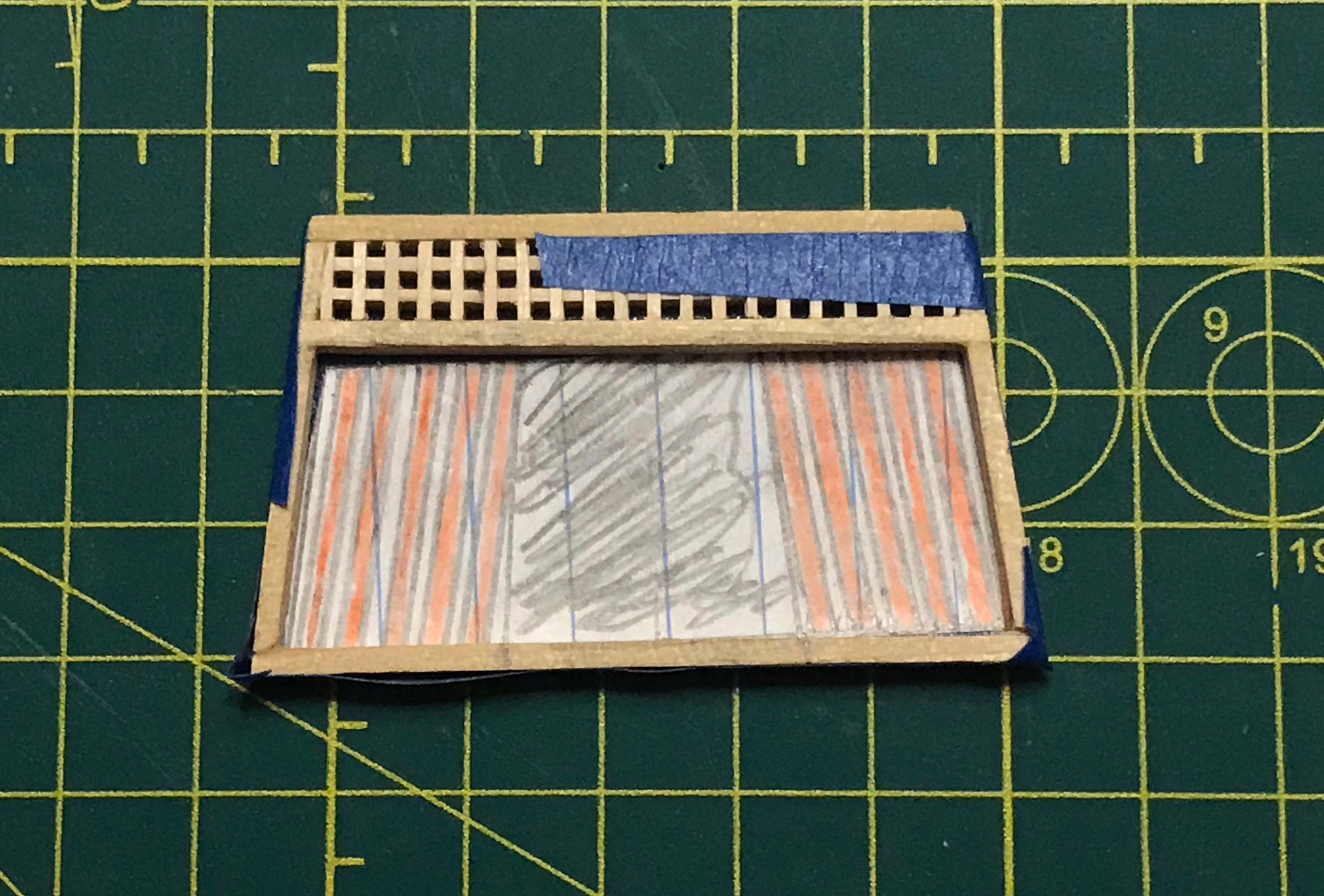
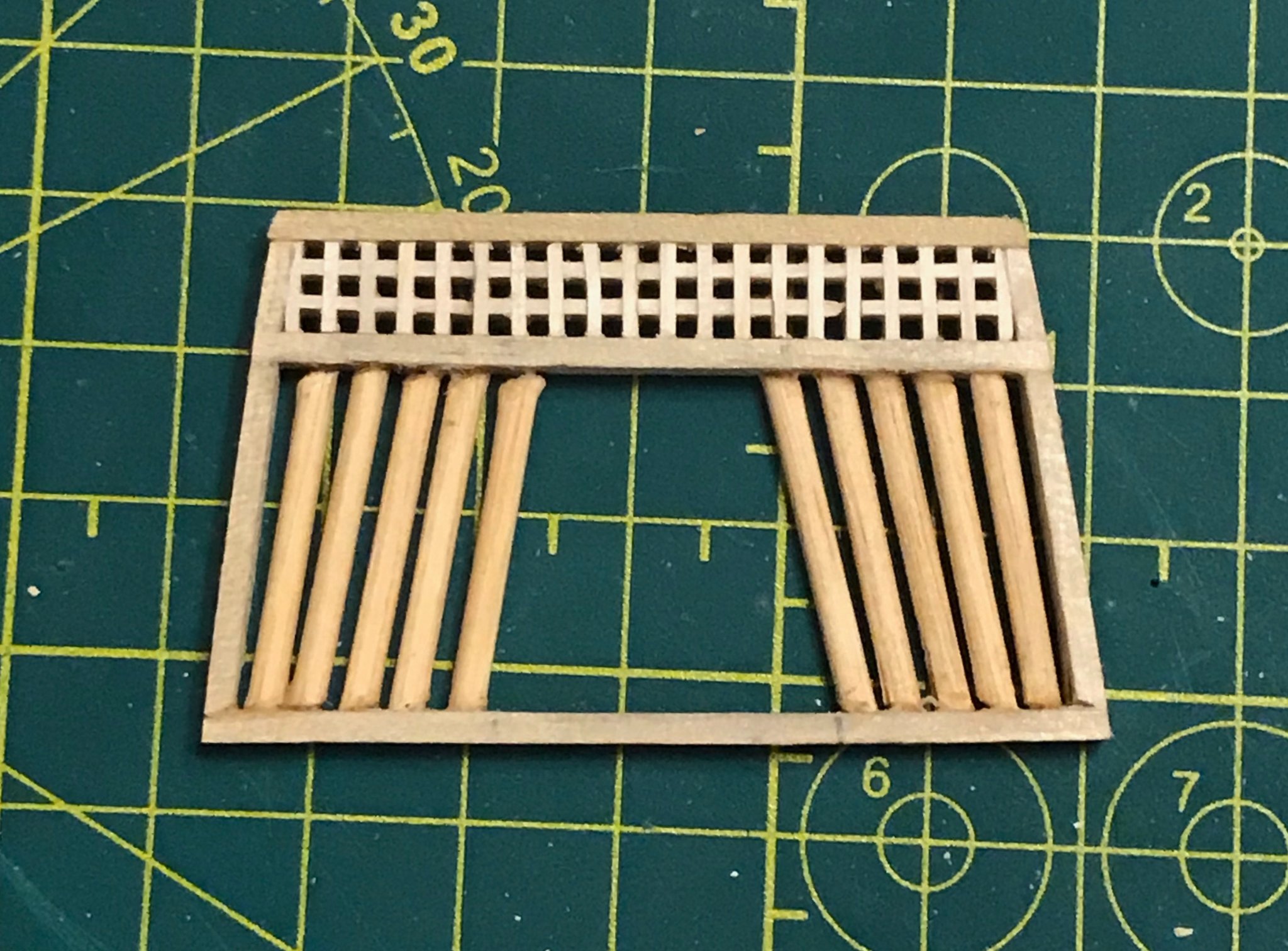
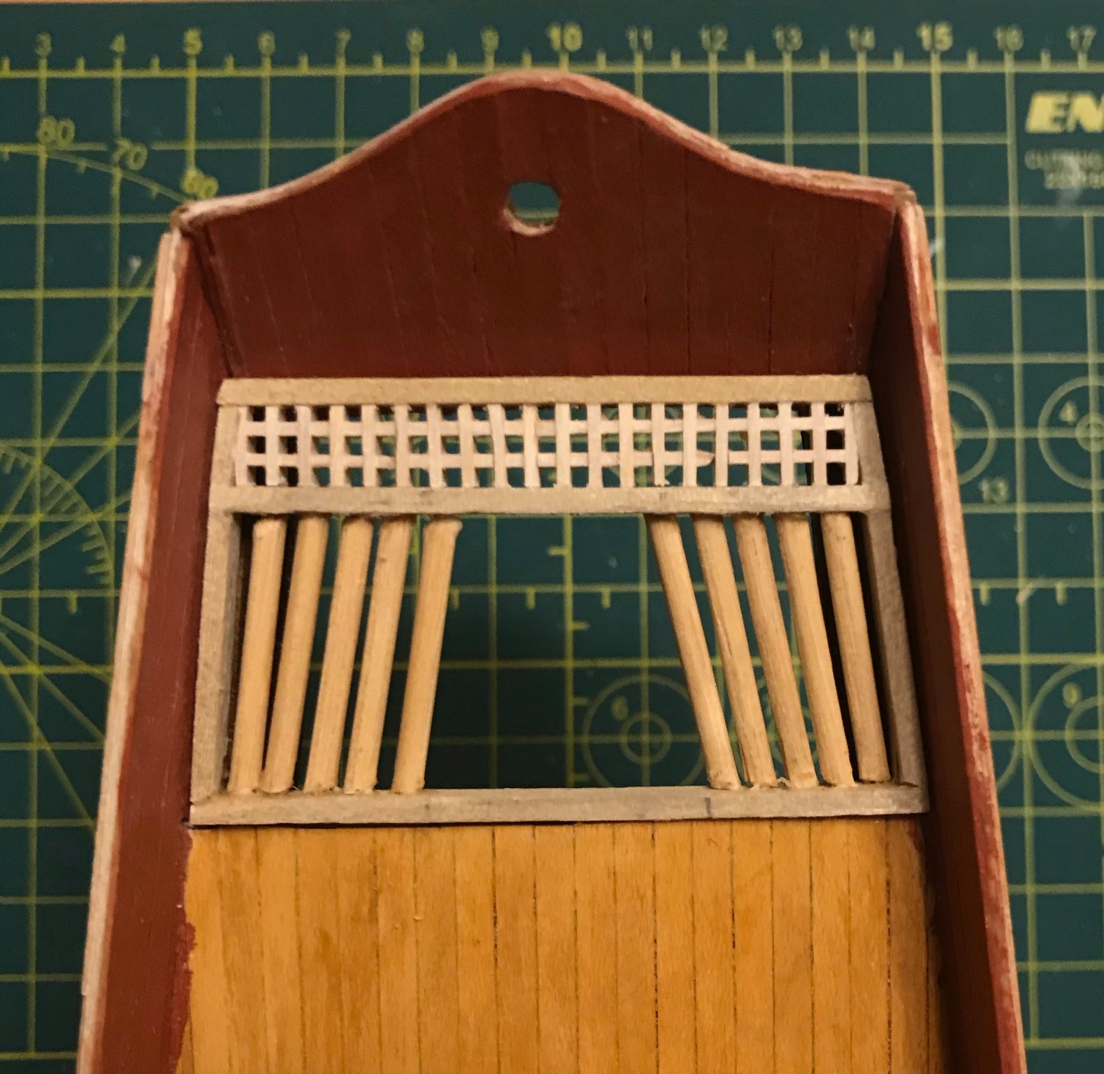
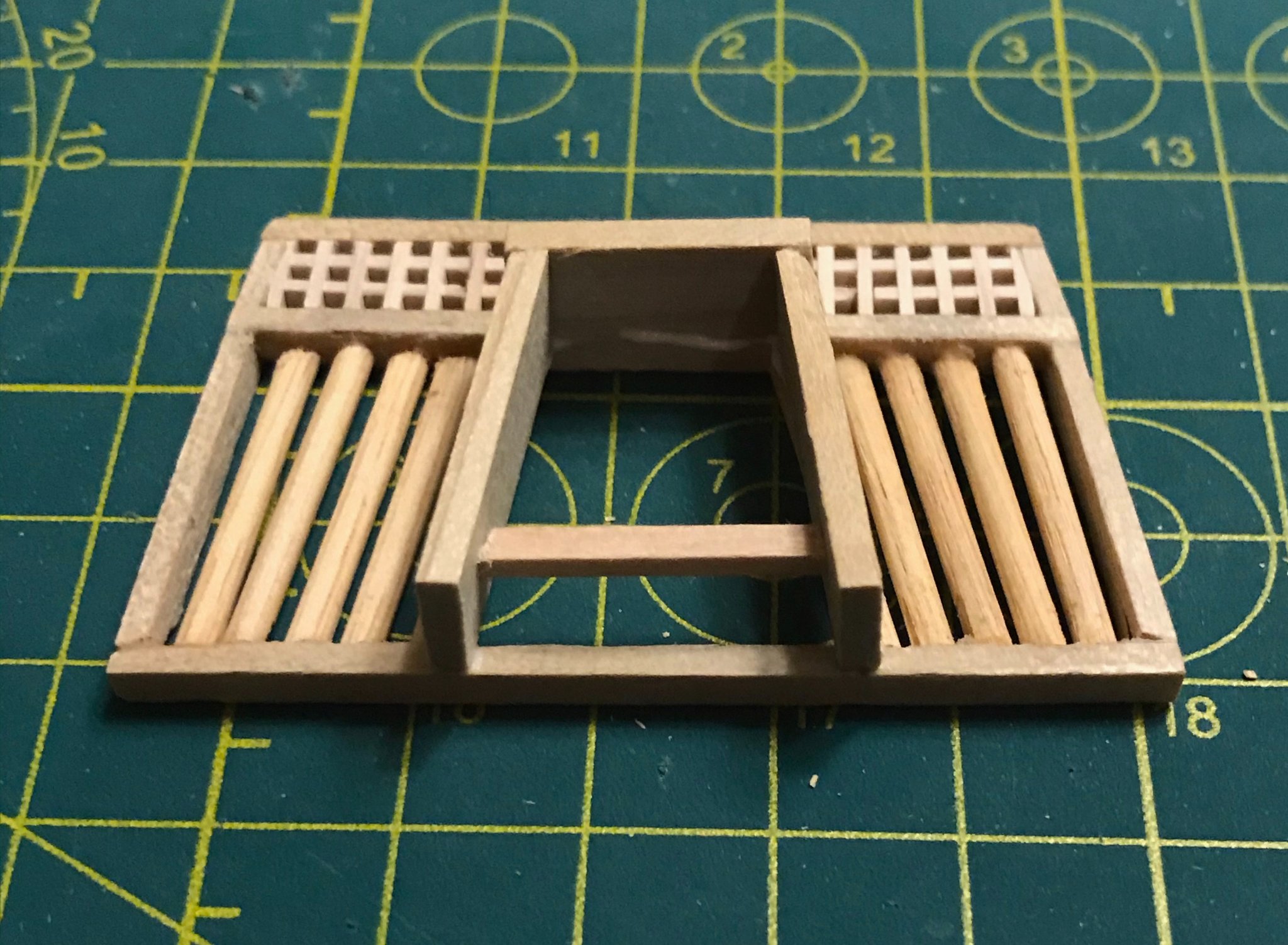
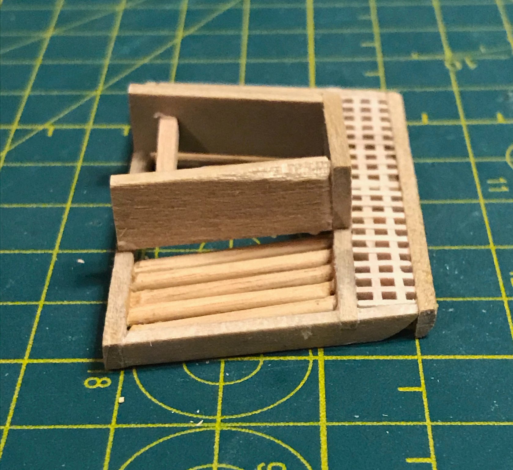
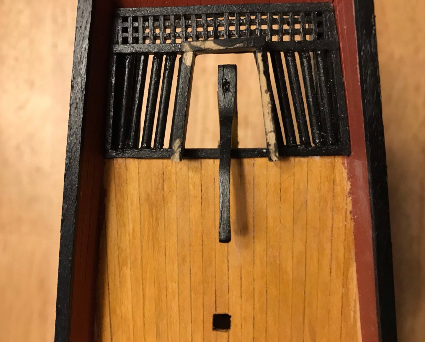
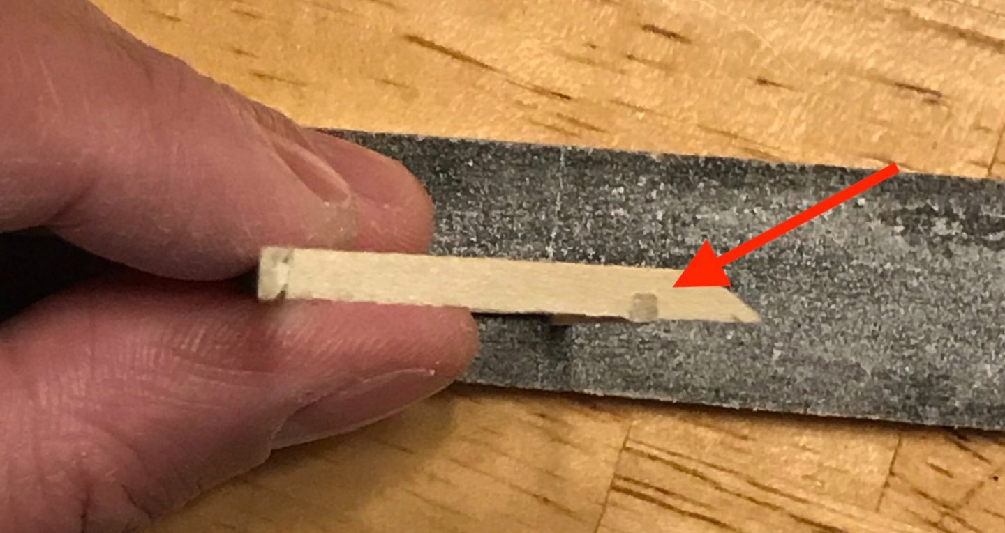
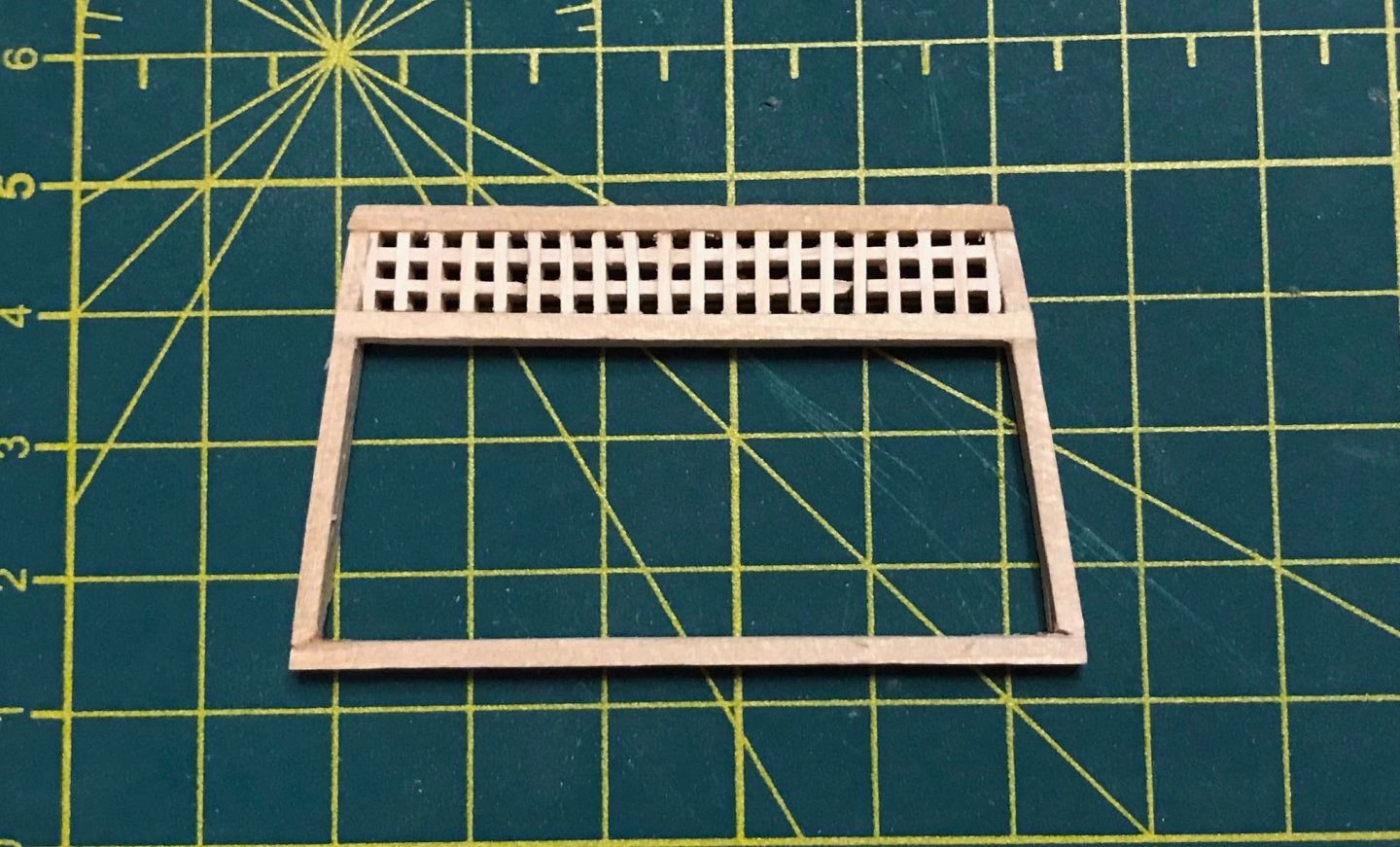
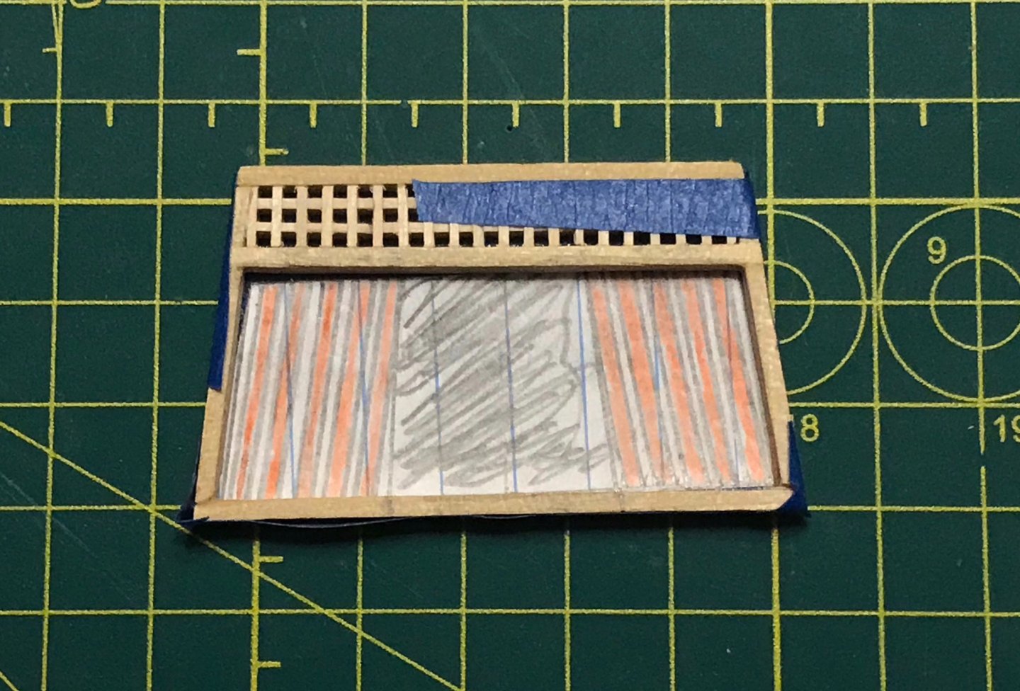
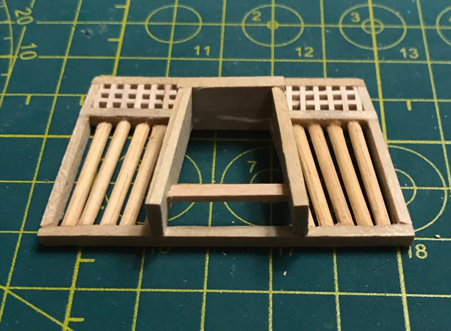
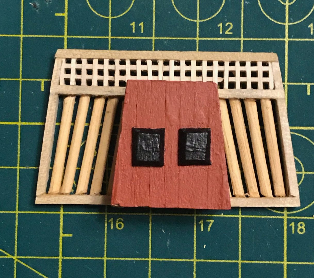
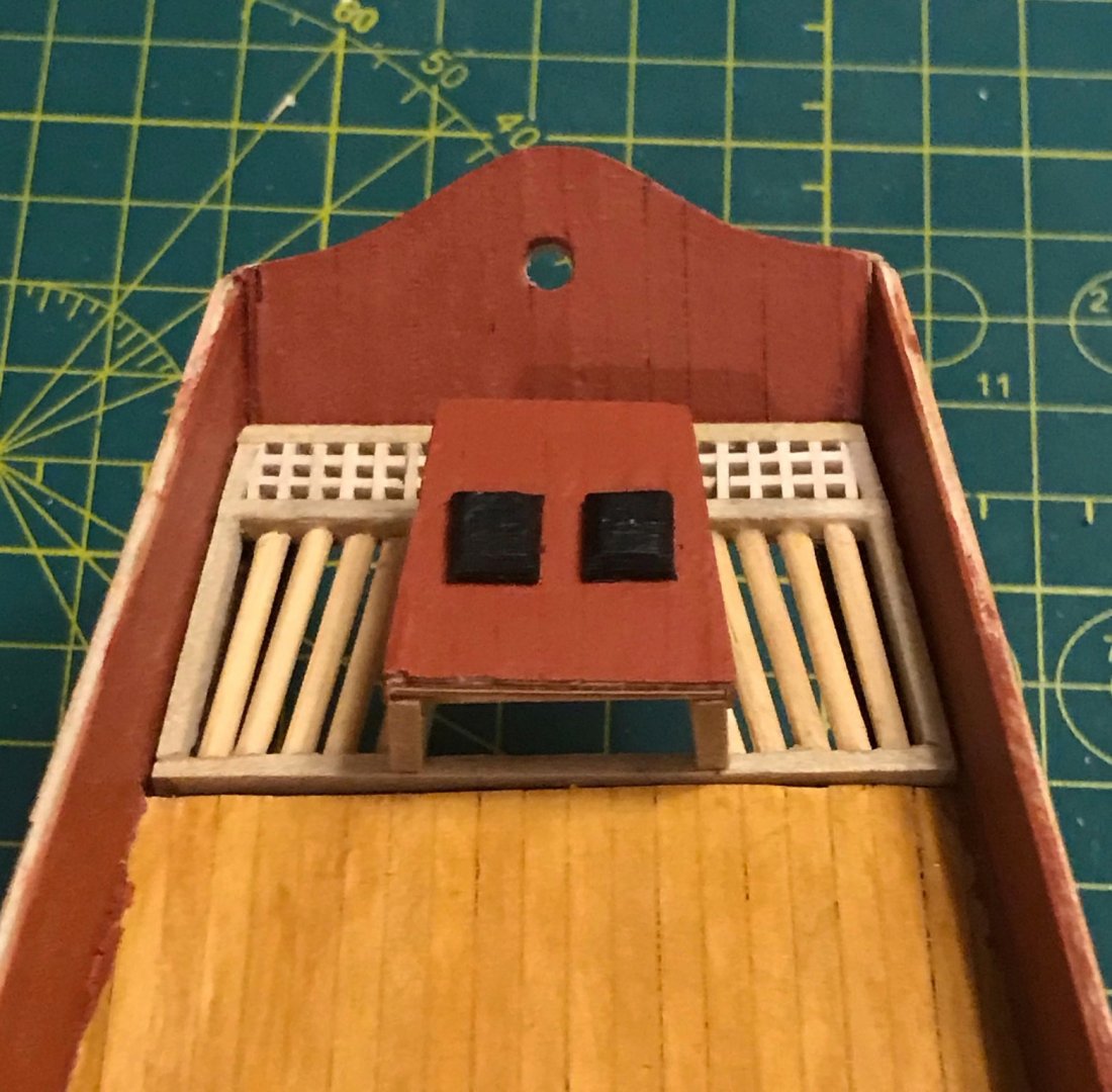
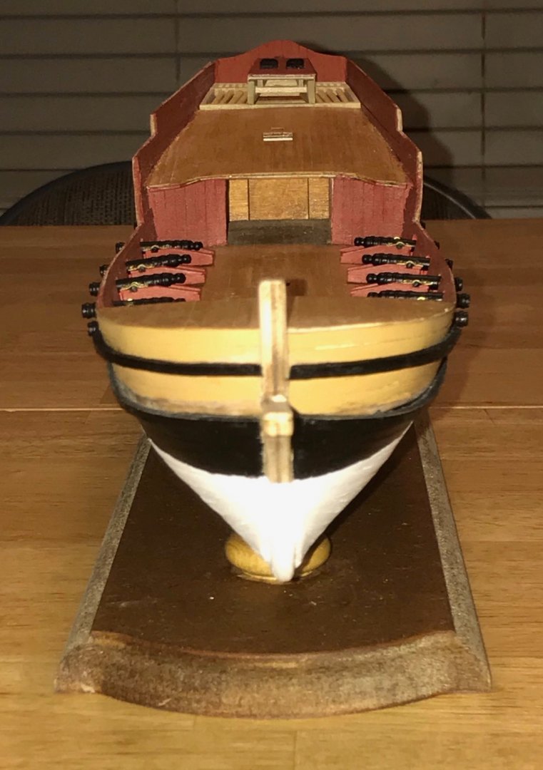
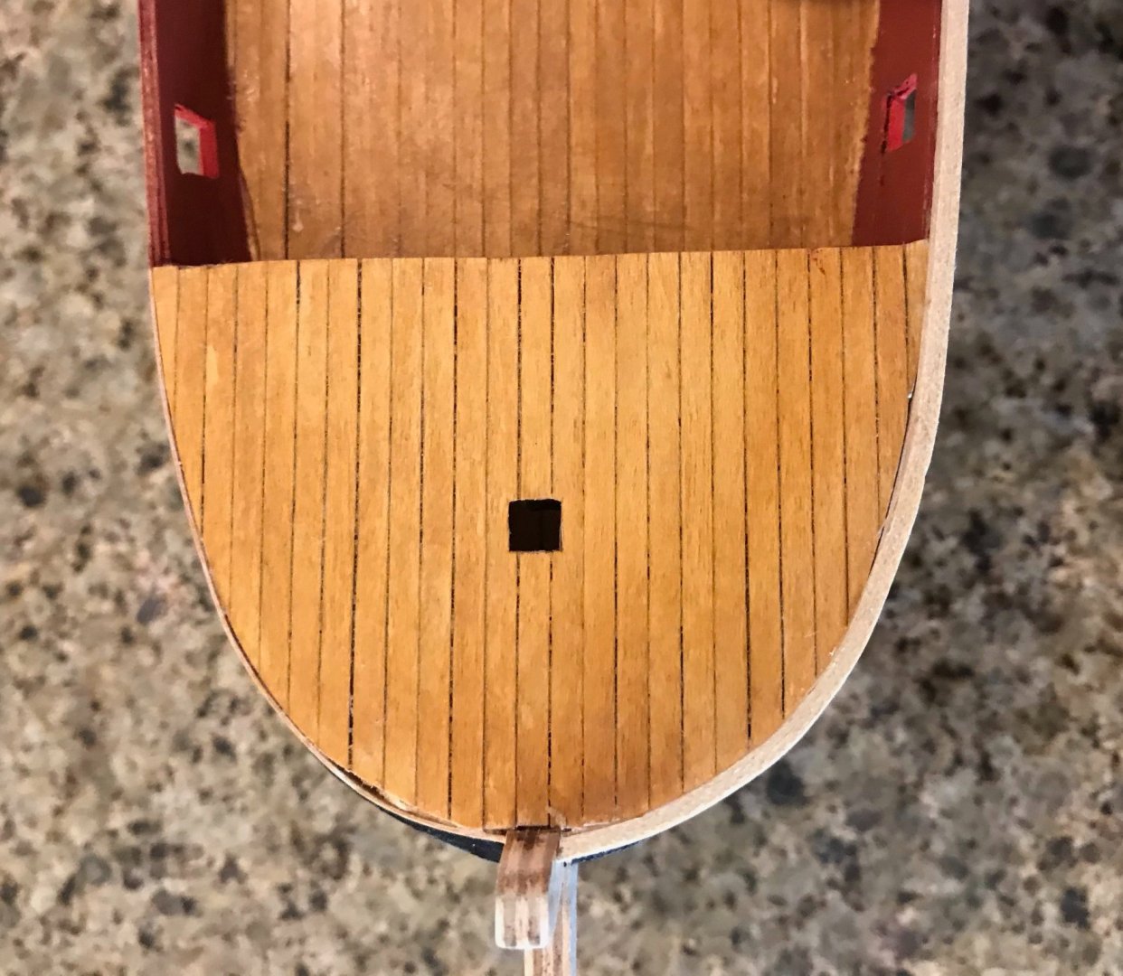
Almost three months ago, I started looking ahead to the work on the rudder well. I made some progress on it, but nothing I'd consider significant. My goal was to build the rudder well assembly into a single unit that could be just dropped into place on the longerons. Once I realized that I would need to put that assembly in place before attaching the gunwales, I decided to finish the rudder well assembly in between coats of paint on the trim pieces. There are a lot of photos here covering most of the steps that I've taken over the last several days. Back in September, I originally measured, cut, and glued the four outer frame pieces. I had also put together the rudder housing, but wasn't quite ready to tackle the rest of the assembly. I started working on this again by attaching the crosspiece. The challenge in locating this was that the front of the rudder housing needs to be aligned with the front edge of the front piece, while the back wall of the rudder housing sits on the crosspiece. Given the various angles involved, I wasn't confident in my geometry and so worked out the placement by trial and error. Once I finally felt confident I had it in the right place, I made some cuts. Inspired by Leo Goolden's Tally Ho videos, I decided to try an overlapping joint. It was a bit tricky, but I'm pretty pleased with how it turned out and I wish I'd done the same at the corners of the outer frame pieces. The photos are an overhead shot of the frame with the crosspiece (the back piece of the frame fell off...which ended up being a good thing) and a side shot featuring the overlapping joint (indicated by the red arrow). Next up was assembling the grating for the rear part of the assembly. The kit comes with lots of grating pieces. After measuring it out, I needed 2 long strips and 20 short ones. Since each grating piece has ten slots, I had to overlap the 2 long strips—the top long strip in the photo is two pieces with 10 slots each, the bottom is three pieces with 5, 10, and 5 slots. Next up, I sand down the grating to fit into the frame. Here's where it was good that the rear piece of the outer frame had fallen off! In the first photo, you can see the assembly sitting in its final place on the rudder well. In the second, I sanded the fourth side and reattached the rear piece. Now that the grating was in, there were more surfaces for glue, so that piece is much more firmly in place and won't fall off again. Next up, I needed to cut, fit, and place ten 2mm dowels into the front part of the outer frame. Five of these dowels are placed on either side of the rudder housing, at 1mm spacing. This was another tricky spot for me. I first tried to place marks on the front and centerpieces, but it made me a bit crosseyed. So, I switched tactics and made a template. The portion of the template shaded grey represents the rudder housing, while the red portions are the dowels. After preparing the template, I taped it onto the bottom of the assembly. Next, I cut and fit the dowels. My assortment of tools is still very basic...I found myself longing for a table saw! But, after making a model out of a 2x2 plank, I managed to cut the dowels using my Exacto knife. Not a quick process, I got the job done. Using the template, I aligned the dowels. I did an okay job, but perfect alignment at 1mm was a bit beyond my skills. These photos show the assembly with the dowels in place, then dropped into place in the rudder well. The next step was to attach the rudder housing that I'd made back in September. The walls are made out of 2x8 limewood. I've added a 2x2 piece as a brace to keep the spacing right in front. (Not to worry, that chip in the second photo will be completely hidden.) Now, a few close-ups of the finished (but unpainted) rudder well assembly with the cover on the rudder housing, first by itself, then dropped into place (but not glued yet). The cover is on to help ensure that the walls keep the correct shape. Except for the cover, the assembly will be painted dull black. Once the rudder and tiller are in place, I'll add a dividing wall between the aftdeck and this assembly. And finally, a few shots of the full ship, showing my progress so far. Just for fun, I placed the cannon and forward hatch cover, though these aren't yet glued into place.


- 79 replies
-
- 2
-
-
- sergal
- sciabecco francese
- (and 1 more)
-
Thanks, Bob! Given that I'm still building up my shipbuilding resources, I haven't had many opportunities to make jigs. So I'm really pleased with how well this one worked out! The idea for my jig came after watching a lot of Leo Goolden's videos about rebuilding and restoring the Tally Ho. Goolden's craftsmanship is inspirational and I've learned a lot about boatbuilding from watching his videos. Hope you're doing better now!
- 79 replies
-
- 1
-
-
- sergal
- sciabecco francese
- (and 1 more)
-
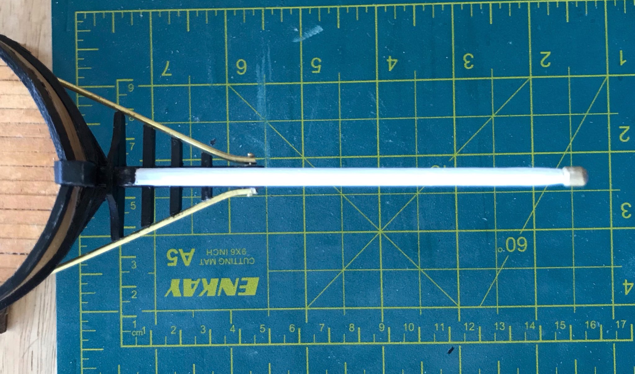
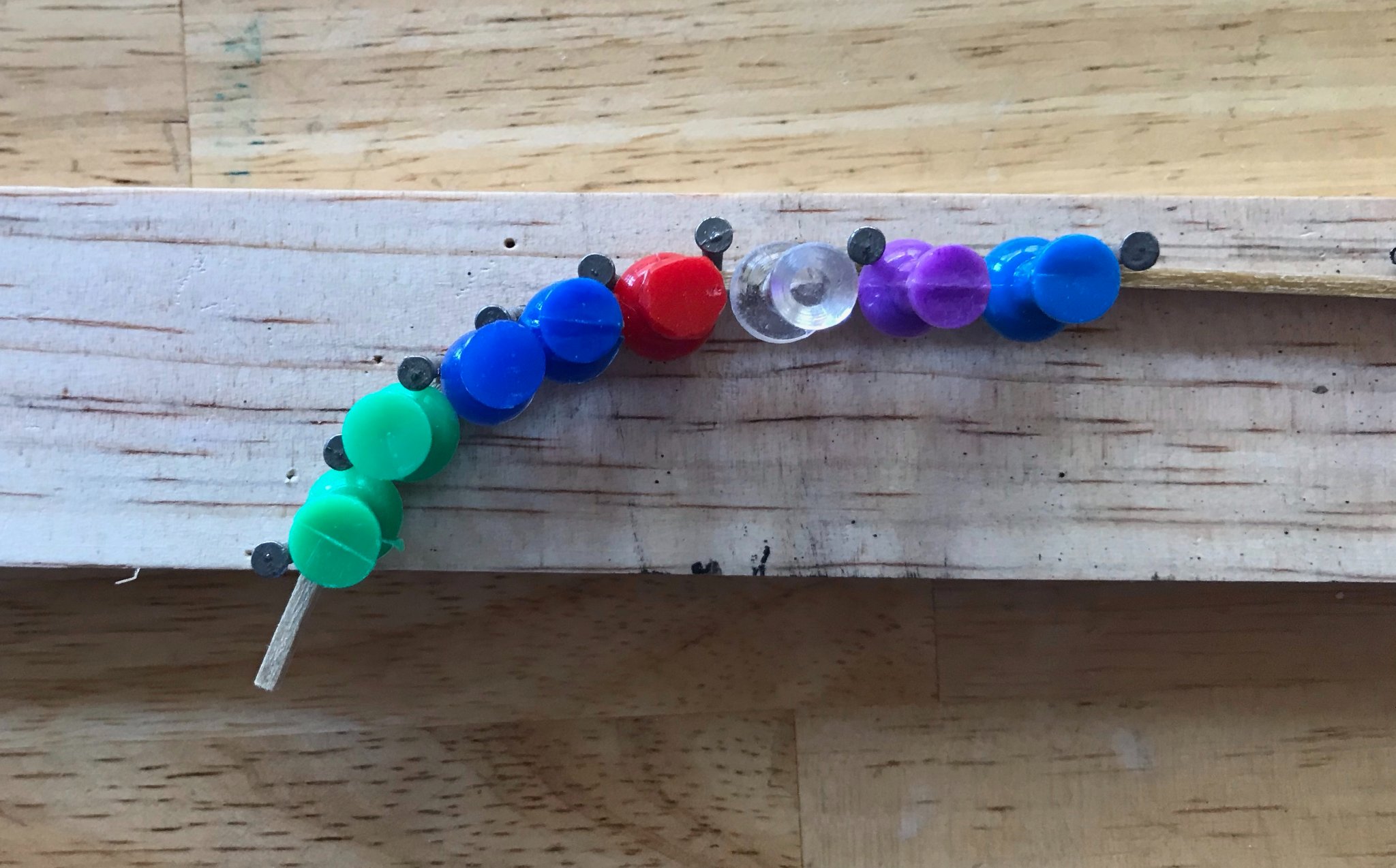
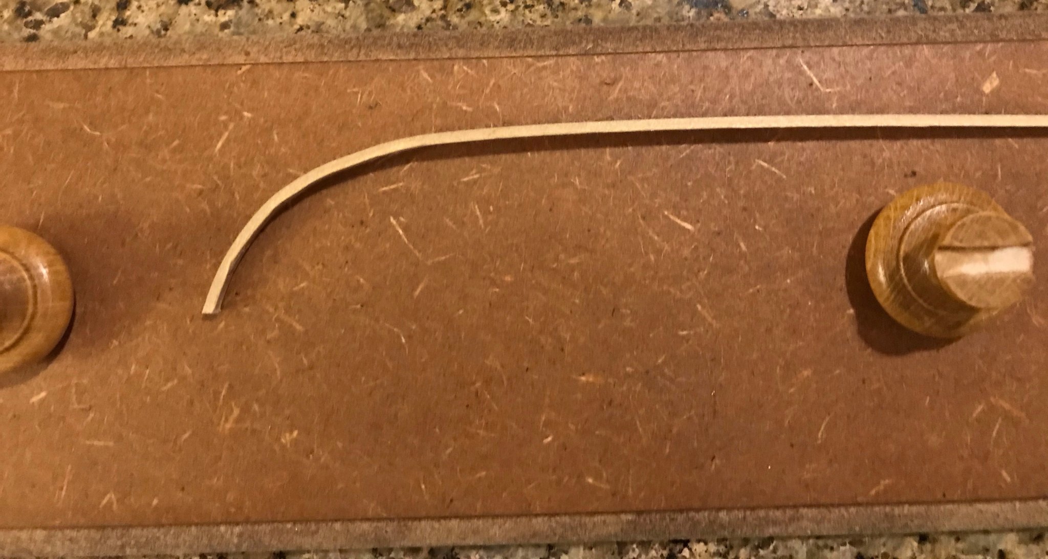
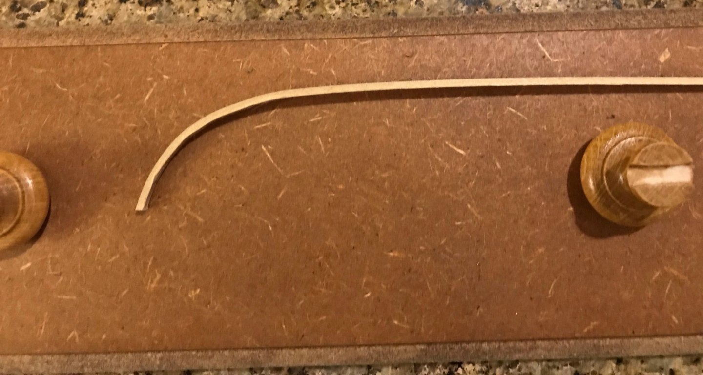
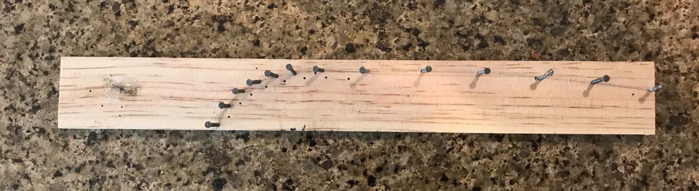
Feeling really great this morning! I had been pretty frustrated with my attempts to bend the 2x3 pieces that make up the gunwales for the foredeck. According to the plans, this piece is supposed to be continuous and curve laterally. Well, after breaking a couple planks, I gave up on that. Midships and back, the 3mm side will be on top. But around the foredeck, the 2mm side will be up (I'm thinking of it as 3x2 instead of 2x3, height-by-width). I'll sand everything down so the two pieces transition smoothly. So, Thursday evening, I decided to make a jig. Since I'm still new in the hobby, I have very little spare wood stored up. However, I did have a short piece of pine wood laying around in my office (leftover from building a stand for our automatic fish feeder). So, I flipped the xebec upside down and traced the shape of the gunwales from the stempost to the point were they will angle up to the aftdeck. Then, I drove in some nails along the line, making sure to have plenty of them where the curve is the greatest. Nothing fancy, but I thought it would get the job done. Having decided to make the forward and midships gunwales out of separate pieces, I focused on the forward part of the jig and plank. I soaked it a little and used a curling iron to give it a little bit of a bend, then began working the plank in. There are 13 nails on the jig, so first I stood the plank against nails #1 (by stempost) and #13. Then, I added a pushpin just forward of nail #13. Then another pushpin just forward of nail #8. From there, I gently bent the plank until it fit snugly against each successive nail going forward, adding pushpins one at a time. Here's a shot of the forward bend with all of the pushpins in place. I left the plank to sit in the jig for a while...I guess 12 to 14 hours? I didn't really time it accurately. At that point. I trimmed off the little bit hanging off by nail #1. Since I laid the pinewood flush against the stempost when I traced the line, the edge of this board gives me the angle at which I need to cut to fit the gunwale to the stempost. Here's the final bend, with the plank resting on my recently stained display stand. And a rough fitting in its final location. I haven't cut the forward bend off yet, since I want to lay the midships gunwales first in order to make sure I handle the transition from 3x2 to 2x3 accurately.
- 79 replies
-
- 1
-
-
- sergal
- sciabecco francese
- (and 1 more)
-
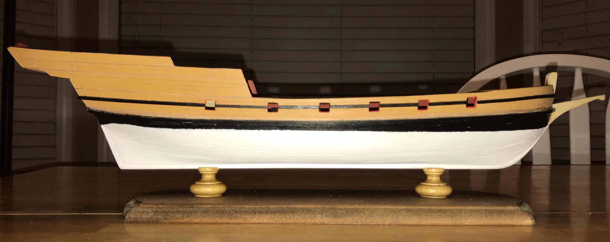
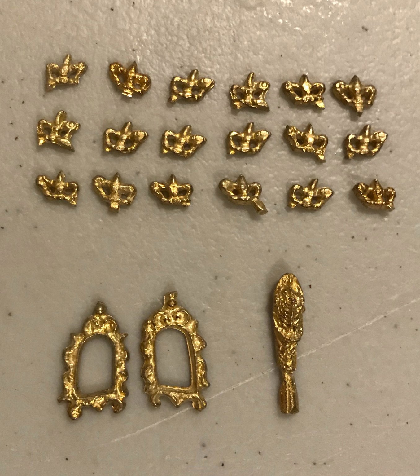
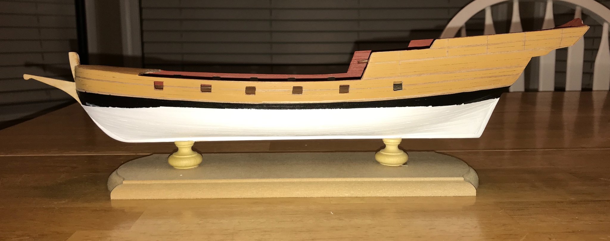
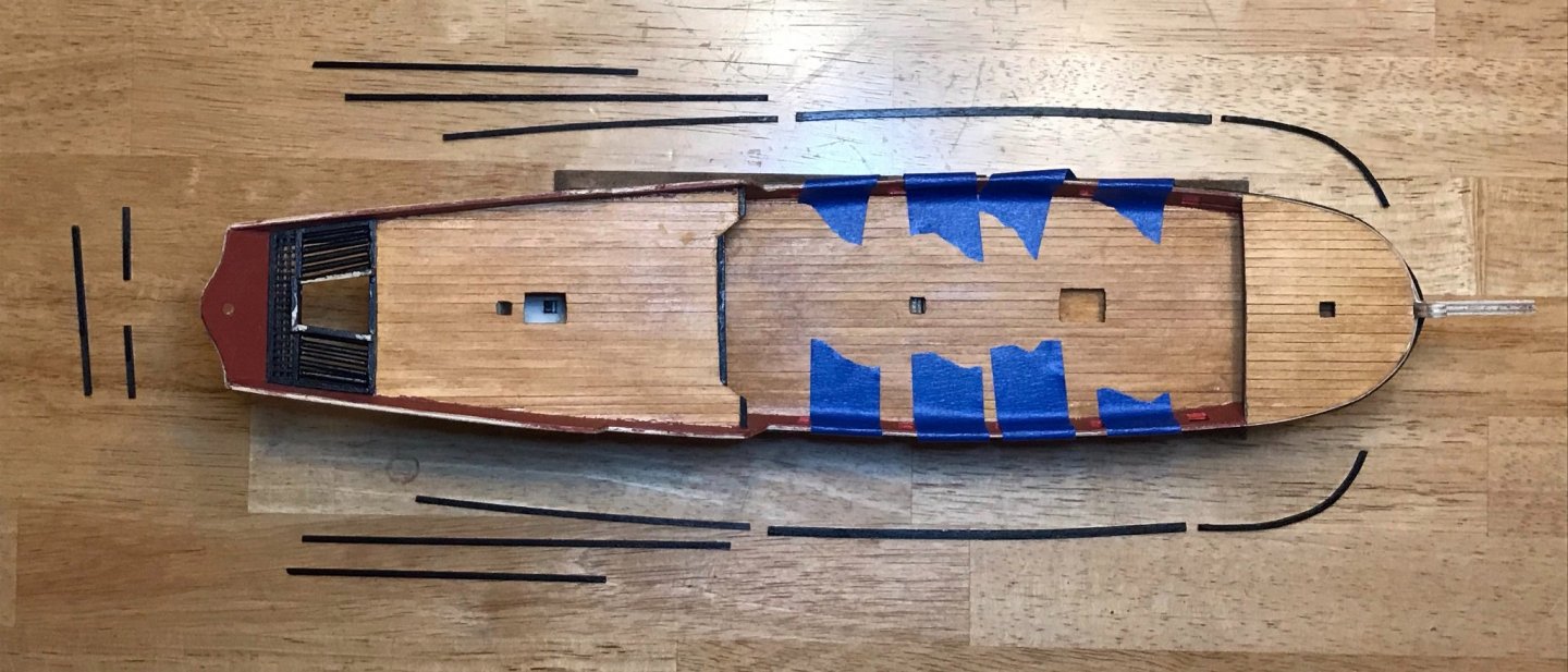
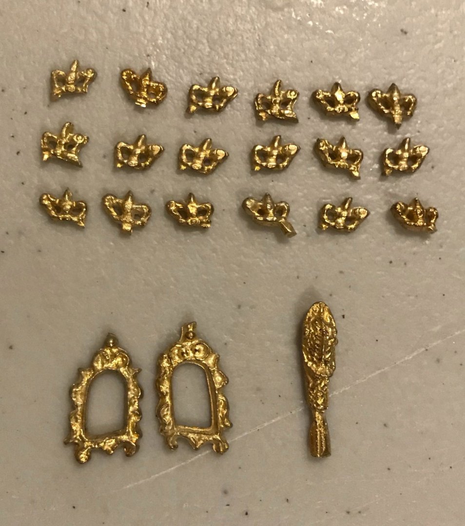
A wild couple of weeks here—including a broken sewer line and a temporary move out of my usual basement work/hobby space—so I have only made slow progress. Three updates to share in this post. First, I've finished installing the hardware on the cannon. I just need to apply some finish and then they are, well, finished. Second, I've finished shaping the trim pieces for the hull and so moved into painting. My plan is to try to keep things a little neater by painting the trim pieces and gunwales first, then attaching them. I haven't gotten to those pieces yet, but have painted the hull. I started by laying painters tape down in all the place on which the trim pieces will be glued. In order to determine the spacing for the trim pieces on the side of the aft deck, I took the brass decorations out of their plastic bag. Ugh. What a disappointment! There are 18 crown pieces that are supposed to line the top row, 2 window frames that are supposed to go on the stern, and a figurehead for the ram. Given how poorly shaped the crowns and window pieces are, I will not be using them. I haven't decided yet on the figurehead...it looks okay from each side, but the two sides are far from symmetrical. I'll make a final decision on that once I get to work on the ram. I still need to touch up the paint job a bit, but I'm mostly pleased with how it's looking. I also aligned the pedestals and base that I purchased, so I can mount the ship on there soon. The base and pedestals are by Amati. Since there aren't any good photos of Amati's pedestals online, it may be helpful to note that these are the 23mm wooden pedestals. The base is MDF, but the pedestals are a nice solid wood...I don't know enough to say which kind of wood. With lots of patience, I used a file to carve a slot for the keel. Next steps: touch up the paint job on the hull, paint and attach the trim and gunwales, and stain the display stand.


- 79 replies
-
- 2
-
-
- sergal
- sciabecco francese
- (and 1 more)