Tom P.
NRG Member-
Posts
13 -
Joined
-
Last visited
About Tom P.

Recent Profile Visitors
-
 Fritzlindsay reacted to a post in a topic:
Floors and futtocks in the Bounty Launch
-
 Fritzlindsay reacted to a post in a topic:
Floors and futtocks in the Bounty Launch
-
 mtaylor reacted to a post in a topic:
Floors and futtocks in the Bounty Launch
-
 mtaylor reacted to a post in a topic:
Floors and futtocks in the Bounty Launch
-
Tom P. started following Floors and futtocks in the Bounty Launch
-
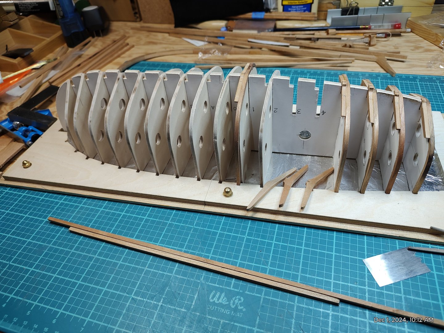
I'm building a more-or-less scratch Bounty launch. I'm bending the futtocks over the forms (shown in the photo), then attaching a floor member to them to achieve the required scarf length. As can be seen, between the stem and midships, the floors are abaft the scarfs, while from midships to aft, the floors are forward. My reading and research prompted me to place them this way (i.e., The Structures of English Wooden Ships: William Sutherland's Ship, Circa 1710, The Northern Mariner/Le Marin du Nord, III, No.1 (January 1993), 1-43. p.12.) and in other places that I just can't remember. My understanding is that ship's boats were built by full-fledged shipwrights, or by men who were trained up in that craft, so that the same construction details and methods were used in both ships and boats. Now, however, I'm in doubt about this. Contemporary models of ship's boats don't always show this arrangement. Most old models show only the futtocks coming up from beneath the bottom; I think the floors were left out because they were not easily seen. Does anyone have any information about this? At this point in the model build, I can easily change the orientation of the floors, but I'm approaching the point where I'll have to decide. Thanks all.
-
Sloop from Roslagen by bolin - FINISHED - 1:50
Tom P. replied to bolin's topic in - Build logs for subjects built 1851 - 1900
Bolin, This looks like a very interesting build. I'll be following it for a number of reasons: I'm also interested in smaller work boats such as this one, and longboats, launches, etc. The big ships are impressive, but sailors were in essence skilled workmen and craftsmen, and that's my background too. With the smaller boats you can get a real sense of this. Also, I'm very interested in how to build clinker hulls: I'm new to this hobby, so there's a lot I don't know yet. What species of wood will you use? The photos show what looks like beech or yellow cedar. -
Those a very fine models. They are beautifully crafted and all the better for being historically accurate. I'm in the process of building the Model Shipways HMS Bounty Launch kit - my first wooden boat model - and I'm a little dissatisfied with the kit. There are significant differences between the kit and the reconstructed launch in the National Maritime Museum in Cornwall. I've been searching for information about how these launches were actually built and when I saw yours I thought maybe you were using the Museum's reconstruction as a pattern. Or do you have other sources of information for it? Another question, if you don't mind: Your model launch has the windlass for handling the anchor, just as shown in the Draught from the Nautical Maritime Museum, Greenwich, which was the basis for the Model Shipways kit. But doesn't that kind of heavy work also involve things like bollards and fairleads/sheaves? The Draught shows none of those, but it is a schematic in some ways. Maybe these launches left the shop in various configurations to fit the ship to which it would be assigned? Or are some details just lost to us?
-
 Tom P. reacted to a post in a topic:
A question about varnish.
-
I have a version of it installed on my laptop. I can't say that I like it much. It is supposed to be based on the IntelliCad software (open-sourced?) that I used for years as a designer for engineered lumber. But in LibreCad the user interface, the way that it accepts input, is very clumsy. I've been reading on this site about other CAD programs, and I hear good things about DesignCad's interface. I'd be willing to pay for it, but I want to access a trial version first. Can't seem to find one of those for the latest version.
-
Tom P. joined the community
-
Square or round tuck?
Tom P. replied to lmagna's topic in Building, Framing, Planking and plating a ships hull and deck
I hope someone out there can help me a question relating to square and round tuck sterns. I'm trying to reconstruct what the Nina looked like - Columbus' ship. As a ship from the late 1400's, I read that she likely had a round tuck stern, that the square tuck became prevalent only in the next century. The earliest definitive evidence that I've found is the wreck of the San Juan in Red Bay Labrador, a Basque nao dated to 1565: she had a square stern. The recovery and preservation of this wreck was such that from the published photographs you can easily see the end grain issue discussed above. I understand that square sterns are easier to construct, but I wonder how they affected the efficiency of the rudder; would they have resulted in more turbulence / less efficiency? I ask this because the Nina and Pinta were reputed to have been good sailors. I would gladly hear anyone's thoughts on this topic. Thanks, Tom P.
About us
Modelshipworld - Advancing Ship Modeling through Research
SSL Secured
Your security is important for us so this Website is SSL-Secured
NRG Mailing Address
Nautical Research Guild
237 South Lincoln Street
Westmont IL, 60559-1917
Model Ship World ® and the MSW logo are Registered Trademarks, and belong to the Nautical Research Guild (United States Patent and Trademark Office: No. 6,929,264 & No. 6,929,274, registered Dec. 20, 2022)
Helpful Links
About the NRG
If you enjoy building ship models that are historically accurate as well as beautiful, then The Nautical Research Guild (NRG) is just right for you.
The Guild is a non-profit educational organization whose mission is to “Advance Ship Modeling Through Research”. We provide support to our members in their efforts to raise the quality of their model ships.
The Nautical Research Guild has published our world-renowned quarterly magazine, The Nautical Research Journal, since 1955. The pages of the Journal are full of articles by accomplished ship modelers who show you how they create those exquisite details on their models, and by maritime historians who show you the correct details to build. The Journal is available in both print and digital editions. Go to the NRG web site (www.thenrg.org) to download a complimentary digital copy of the Journal. The NRG also publishes plan sets, books and compilations of back issues of the Journal and the former Ships in Scale and Model Ship Builder magazines.


