


apprentice
-
Posts
30 -
Joined
-
Last visited
Content Type
Profiles
Forums
Gallery
Events
Posts posted by apprentice
-
-
In the late 1960s I visited the Maritime Museum in Greenwich, London. It was full of ship models on display. What left an everlasting memory were the prisoner of war models from the Napolean War. The POWs were allowed to sell handicraft for money to supplement their ration. For some reasons, quite a few of the POWs were craftmen in clock making and they made use of their skill to make models of ships that they sailed with. They made the models from memory, without plans. So they were not 100% accurate in all aspect. There were a few that were a combination of two different ships. But the detail work were exquisite. It was that visit that I got interested in ship modelling.
I visited London again in 2012 during the London Olympics. The first thing I did was to go to the Maritime Museum. It has changed completely from what I remembered and the POW models were not on display. I asked the staff of the museum about it but they don't even know what I what talking about. It was a huge let down for me.
It strike me that some members might know about these POW models. What happened to them now? Are they on display somewhere?
-
Let's say you want to work from the wale towards the keel. From the measurements we made on the perimetric length of the frames, we have decided there are 5 belts, the widest in mid ship is 20mm and we need 5 strakes to fill up the belt.
If we install the battens above the marks on each frame in the direction of the keel, then the distance from the wale line to the 1st batten will be 20mm at the midship frame. What we need to do now is to fill up the belt with 5 strakes. Once we have done that, there is no space between the 5th strakes and the batten. Now we can remove the 1st batten, the distance between the edge of the 5th strake of the 1st belt and the 2nd batten will again be 20 mm. We can repeat the process. When we reached the last belt the distance between the edge of the strake and the keel will be 20mm once the last batten is removed
Alternatively if we prefer to work from the keel towards the wale. We install the battens below the marks in the direction of the wale. The distance between the midship frame and the keel for the 1st belt will be 20mm. When we eventually remove the last batten, the distance between the edge of the strake and the wale in the midship frame will again be 20 mm.
Only remove the batten after you have spilled the 5 strakes for the belt you are working on.
-
11 hours ago, Y.T. said:
Wow, Apprentice . Your process description is the best I ever read either on the forums or in the published books! Excellent. If I was a moderator I would pin this to the board in section dedicated to planking.
Thank you for your kind words. I am only a temporary assistant apprentice shipwright , on probation
")
- thibaultron, lmagna and mtaylor
-
 3
3
-
Hi Zack
The following is a simple description of how to plank a hull. Hope it helps.
First thing is to locate the wale line. This is the the strongest part of the the hull with reinforcement. The position of the wale line should be given in the plan of the kit. From the wale line upwards, the planks (technically known as strakes) are uniform width. You can use the stipes supplied and plank the portion from the wale all the way upwards.
Next measure the parametric length of each frame from the wale line down towards the keel and record the figures.
Using the frame in midship (the largest one) as a reference to decide how many planks are required to cover the enitre side of the hull. For example, if the parametric length is 100 mm and you are using 5mm width strips, then theoretically you will need 20 strakes to cover the hull. But that means that in the midship section, there is no room for error because the strake is exactly the width of your stripe. It is best to allow some room for adjustment. Let's say if we decide that at the mid ship the strake should be 4.0mm then there should be 25 strakes along the hull.
If you start planking 25 strakes in one go, accumulated error will build up and by the time you reach the end, the strakes will not fit. To overcome this problem, divide the hull into along the parameter of the frames into belts. Using the example of 100 mm mid frame to fit 25 strakes, the hull can be divided into 5 belts with 5 strakes in each belt.
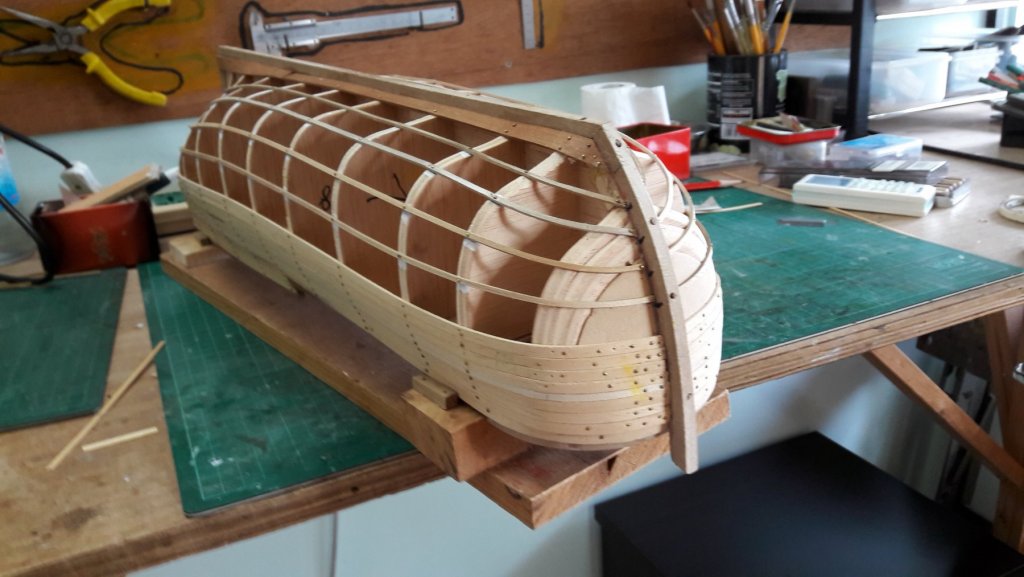
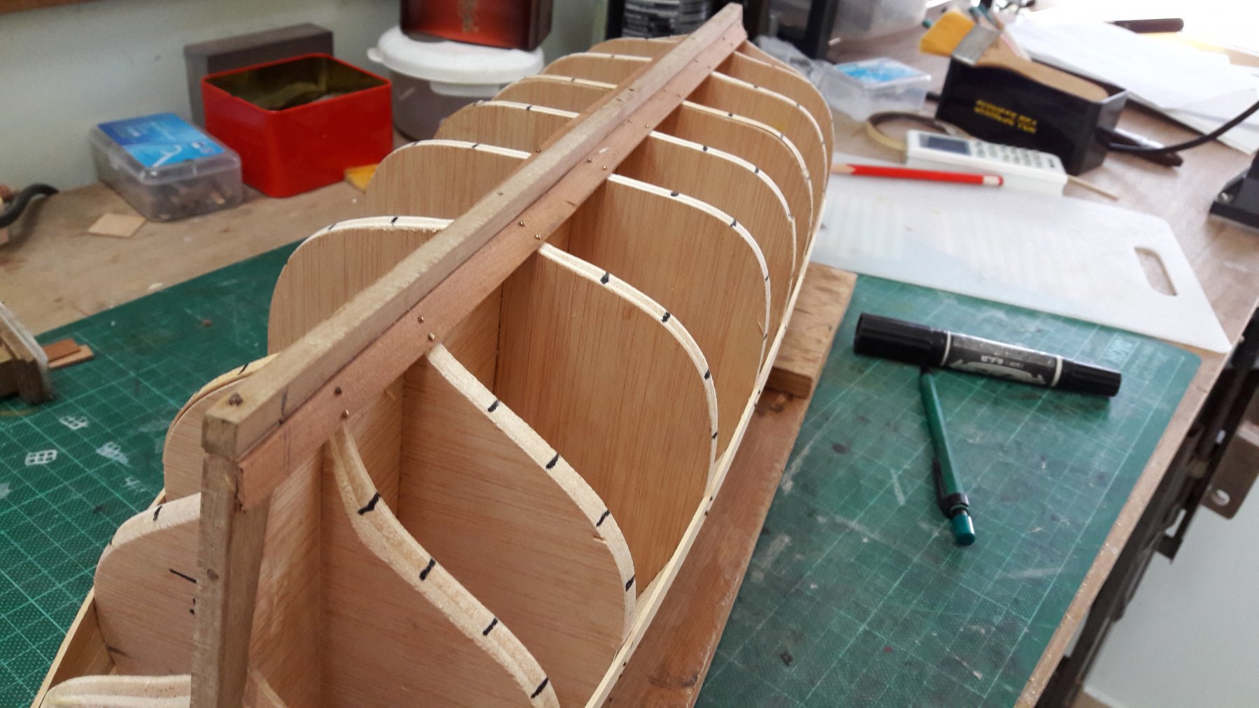
Now that you have decided on 5 belts, divide the parametric length of each frame by 5 and mark the position on each frame with a marker pen (photo 1). One point to bear in mind is that the narrowest portion should not be less than half the strake width. Battens are guides to define the belts and give you an idea how the hull looks like before the strikes are in place. 2x2 mm strips is a good choice for battens. Soak the battens in water over night so that they can bend easily over the shape of the hull and installed them on the hull following the markers (photo 2). If you want to work from the wale line downwards, the battens should be installed ABOVE the makers. If you want to work from the keel upwards, the battens should be installed BELOW the makers. The idea is that the first belt you will be working on should have the width of that you have worked out before hand. In this example, the space between the batten and the wale line should be 20 mm measured from the wale line if you work from the wale towards the keel.
Measure the distances between the batten and the wale line for each frame and record them on a piece of paper or a spread sheet programme. Divide each distance by 5 to give you the width of the strake at each frame. Mark the distance between the frames on a stripe. At each position where the frame should be, mark the corresponding width. Join these marks with a smooth curve and shave off the extra material to give you the first stake that should sit on the hull next to the wale. Pin the strake onto the frame. Now that you have installed the first strake, measure the distances between the first strake and the batten for each frame again and divide it by 4 to give you the dimensions of the next strake and cut it to the width required. When you have completed the 5 strakes required, remove the first batten and proceed to the next belt. By constantly adjusting the width we will prevent accumulated error from building up
As a first attempt on ship modelling, I think it is best to work on a clipper style of hull where the strakes run straight along the entire hull. The example shown in the photo is for a 17th century ship (the Endeavour) with a curved bow that requires different treatment at the bow. If you are interested in how to do it, send me a PM and we can discuss it further.
All the best
Wing Chau
aka Apprentice

- thibaultron, GrandpaPhil, vaddoc and 11 others
-
14
-
-
I have built the Alabama. One thing you need to watch out is that the strips for planking provided is a little too thin. When planking the Alabama, I suggest you add more wood to the keel-frame assembly otherwise the planks will not sit well with one another. Or replace the supplied strip with thicker ones
- mtaylor and John Allen
-
2
-
I used to use planking clamps but stopped using them because I found sooner or later I run out of place to attach the clamps on the fames. Now I soak and bend the wood then hold it in place with pin on pre-drilled hole on the frames. I have two types of pins, one slightly thicker than the other. For the thicker pin, I pre-drill a 0.5 mm hole, for the thinner one, I use 0.3 mm drill and push the pin through. It held its place wel. After the glue dried I remove the pins. Before sanding the hull, I coated it with white glue to fill up the holes left. I don't find any problem with this procedure.
-
I bought the Model Shipways "Rattle Snake" at half price during one of their sales a few years ago. Recently I decided to have a go at it. It is the most disappointing kit I have come across so far. The frames are laser cut from a very fragile soft material that breaks easily. I damaged two of them while assembling the keel and frames. Funny thing was that the blocks of wood supplied for carving into fillers for the bow and stern are reasonable hard material. Only soft wood is supplied for everything else, including parts that are traditionally made of hard wood, such as the cover plates and the rubbing strips of the hull, the keel plate and rudder. Included as laser cut prefab parts are the window frames, again in soft wood. These are so thin and fragile that one needs the steady hands of a skilled surgeon to handle them. The most laughable are the Britannica metal cast parts which Model Shipways bought en bulk from their Chinese supplier. They didn't bother to remove the Chinese price tag attached to the plastic beg. Unless one is willing to fabricate and replace a large number of parts with better material, it is going to be a 'cheap and nasty' model. After a frustrating week working on it, I decided to put it aside and start of the AL Endeavor
No wonder it was offered at half price.
-
this weekend has been all about the main stairs
i have been pondering about it and lookign at how others tacled this construction
they always say to cut things in bite size portions and thats what i did
the curved part consist of 8 steps making 180 degrees or 2 times 4 steps making 90 degrees
4 steps seemed doable so i started preparing :
i drilled some holes so that the dowels would be as deep as the point where the curved steps start
from the left over from the sheet they came from i cut 6 small bits
glueing them together to create a platform to rest the curved steps on while the glue dries
at the base i glued a piece of strip against the middle of the dowel to push the first step against
i used a metal angle bracket to measure the 90 degree angle
i formed the platform a bit more so it would fit. all the elements are now ready
the 4 curved steps glued in place
after creating 2 sets of 4 steps i remembered i needed the others to curve the other way so i glued the base on the other side
Hi
Just found your building log, great work!!

I am also building the Mississippi and is I having problem with the staircase. As far as I can acertain, the anlge for the steps that make up the curved portion is 22o. Eight steps only give 176o when lined up side by side. With some for overlapping to glue them together, the angle is less than 90o by some way. How did you onvercome this problem?.
Thanks for your advise.
apprentice
-
Hi Russ
Sorry I did not make the point clearly.
I was referring to ships of the 17th century era with 14" wide stracks. If the longitudinal curvature is not severe, the shipwright would spill the plank to follow the curvature because that will be the easiest way. But the size of the planks is limited by the size of the tree where the timber is harvested. At the bow where the curvature is too large for the timber available, the shipwright will have to use timber with a natural curvature. See:
http://www.cnrs-scrn.org/northern_mariner/vol03/tnm_3_1_1-43.pdf
-
For wooden hull ships of old days, planks were cut so that they butt into each other following the shape of the hull. Sometimes these planks had to be bent to follow the curvature. In certain part of the hull such as the bow the plank had to follow curvatures in both longitudinal and lateral directions because the hull is a 3-D object. The shipwright would then choose from a stock of planks with built in curvature in the longitudinal direction best fitted for the purpose because it is much easier to bend a plank in the lateral direction. In ship modelling, we tried our best to plank the hull so that the stracks lay comfortably without twist following the profile of the hull. Spilling gives the strack the correct curvature in the longitudinal direction, then soak in water and heat bend it to follow the lateral curvature is the most effective way to achieve the objective.
-
Hi Russ
Come to think of it, three strikes are the minimum. number to form a butt joint. Four is possible, but above four it is difficult to imagine
-
Hi Russ
Yes that is what I meant. As I understand it, a butt joint should be form with not more than three strakes, and that a joint should not line up with the one below or above it unless there are three strakes between them. I thought these rules are meant to minimise water sippage into the hull, the same as the half strake width rule.
-
In the article "Planking a bluff bow" by Colin Lloyd, there are pictures showing full drop planks in a full size ship. In the last photo of the article the drop planks were highlighted in blue. Two drop planks start from the same point. At the tip where the two planks join up with the half drop plank there are four 'outlets'.
Is this not a violation of not more than three 'outlets' rule for planking? Or is it that the rule need not be straightly observed?
Thank you for clearing up this point for me.
-
I use ca only when it is absolutely necessary (not possible to clamp the parts together). The important advantage of wood glue is that if you want to correct a mistake or not happy with a part, just place a piece of cotton wool soak in water over it overnight, and the part will come off easily. You can't do it with ca without damage to the surrounding.
One point about ca is the setting time. It will set very fast (with the thin ca within 8 seconds) if it is a very thin layer. The setting time will be much longer if a large droplet is applied to the parts to be clued. Dirt and Oil of any description is detriment to the strength of a cured joint. Make sure clean the joints using alecohol to remove finger makr and the like. The parts to be joined by ca must be perfectly matched otherwise only the high bits that touch wach other bond together while the rest is not bonded; resulting in a weak joint.
In conclusion, I think ca is a difficult animal to handle.
-
I am building AL's Mayflower. I divided the hull into bands and installed batans on the hull before planking. The batans ran naturally along the hull that ended sharply in the bow. In two bands, the width at the bow is just over two half strack width, with one band its half strack width. I spilled the stracks and install drop planks in the second planking. With two bands, its five stracks into two, with the other its five stracks into one. How can I install only one drop plank at the bow in this case? Have I made a mistake along the way? I have a photo of the hull after the first planking but I do not know how to attach it with the massageIn most cases both...but only one drop plank at the bow usually.
Chuck
Appreciate if you could give me the benefit of your experience.
-
-
Hi Tom, LFrankCPA
Thank you for the reply. I had a look at the links, they look good, but he does not sip outside USA.
 but I finally managed to locate a local supplier that sells off cuts at a very reasonable price.
 -
-
Thanks, but I do not live in US. Is there someone who sell veneer by small quantity on the internet?
-
Can someone tell me where I can buy small quantity of 0.5mm (3/128 inch) thick oak veneer or nearest, say 2m length (6ft) of standard width ? The suppliers I found so far only want to sell in bulk.
-
After the "math" is done and max plank widths are determined, I suppose 2 or 3 of the supplied planks could be glued together giving you a wider surface to accommodate the "spiles"........
JP
I tried it once and found it does not work well because the glueline is much weaker than the rest of the mateial. I keep a small stock of 0.5mm veneer for spiling. The trouble is veneer is available for a variety of wood but oak veneer is hard to get hold of. I ended up with teak for the spiled strakes and oak for the straight bits


Napolean Prisoner of War Models
in Nautical/Naval History
Posted
Thank you for the information. So I have went to the wrong place. 😭 Unfortunately I do not have plans to visit either London or Canada, and might not have the chance to see these treasures again. But I will defintely try the websites of the Royal Museums. It will bring back many happy memories