
HOLIDAY DONATION DRIVE - SUPPORT MSW - DO YOUR PART TO KEEP THIS GREAT FORUM GOING! (Only 20 donations so far - C'mon guys!)
×


Fuji
-
Posts
56 -
Joined
-
Last visited
Content Type
Profiles
Forums
Gallery
Events
Everything posted by Fuji
-
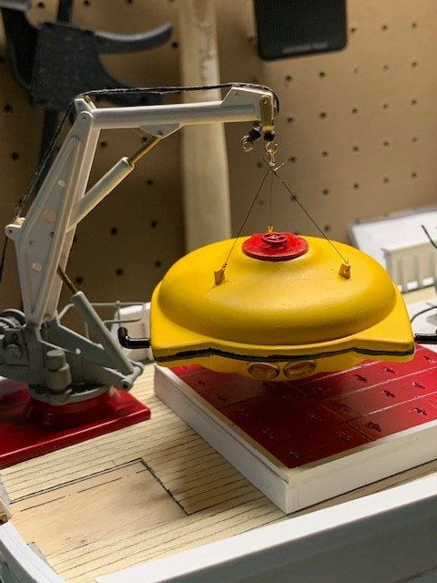
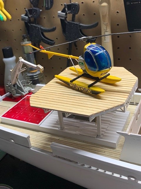
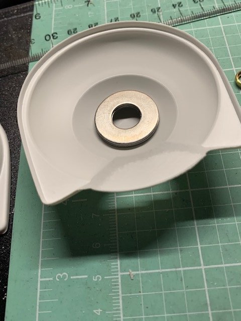
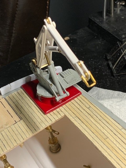
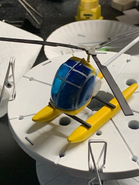
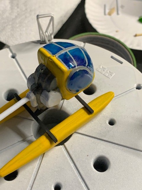
Got a little more done on the Calypso build the past few weeks! Completed the helipad! I originally only assembled the very thin and flimsy truss for the helipad but when I started assembling the surface of the helipad the misalignments and warped truss framework started to work out with the help of styrene strips and the wooden planks! Then built the columns for the helipad and dry fit everything together. Will permanently attach the helipad to the support structure then the entire helipad to the deck once the upper deck has been installed to make sure everything is squared. Pretty happy how it came out so far. I next completed the Hughes 300 helicopter by adding the decals... err... stickers. Was disappointed in how poor the decals were as they are quite old and lost some of the adhesive due to the decal backing sheet warping. I discovered that if I was really careful and applied styrene liquid cement along the edge of the decal, the decal would adhere along the edges to the surface! So far so good! I finally started building the submersible saucer! To add realism to the display I added a couple of metal washers inside the body to add some weight. After assembling the two halves it was a quick add of the maneuvering jets using insulated wire and a quick paint job. Had to hand paint the rubber bumper all around the body, but overall I think my hand was steady enough. A few blotches but it was easily covered up with another coat of yellow. "Stole" a handwheel from the wench assembly below the helipad (hey you wouldn't be able to see it anyway!) and added it to the submersible hatch (this you WOULD see!) for realism. The last step was to add cable to the crane. I used waxed thread normally used to make bracelets from the hobby store even though the hook attached to the cable isn't what's used to launch or retrieve the submersible. BTW - The kit didn't come with any hooks for the crane (or at least I couldn't find any) so I scratch built them using spare brass eyelets and glass beads from the Virginia wooden ship model. I think it came out pretty good! Finally I scratch built and added lifting lugs to the submersible instead of just adding the metal eyelets which came with the model. They are a tad too big per scale but honestly I couldn't make them any smaller if I tried! Then it was adding slings to the submersible and attaching them to a lifting ring. I was pretty happy on how the submersible hangs below the crane and will only now need to trim away the excess thread from the slings to complete. But wait! shouldn't I add the lights etc. to the submersible? Hmm.. maybe not quite complete yet! LOL! Planning on painting the hull this weekend as long as the weather stays sunny and warm! More to come!
- 70 replies
-
- 7
-

-
- calypso
- billing boats
- (and 1 more)
-
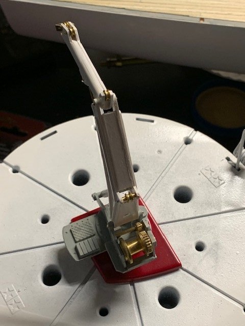
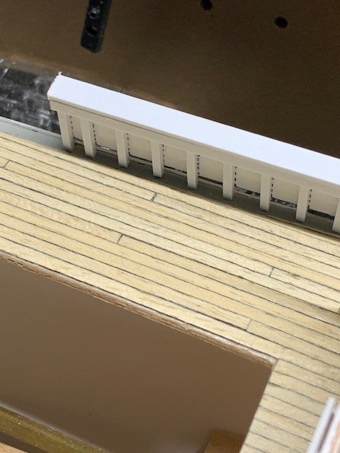
Had some great weather this weekend but was still able to dedicate some time on the Calypso between being outside enjoying the warmer temps and sunshine! I started building the crane at the stern of the ship. Got the pulleys and hydraulic cylinders temporarily installed for now. Need to file down the wire used to hold these items in place then add a drop of superglue and eventually paint over the ends of the wires. Ordered some thin and flexible wire online for the crane and will install that when it arrives. Built up the handrailing using Evergreen styrene rather than the wood strips provided with the kit. The results are in my opinion much cleaner so I'd highly recommend doing this! I also added some small pieces of along the door edges to simulate the door hinges. Fun! Paint seems to be coming out too think. Probably because it was in the mid-50's the day I painted so I'm going to sand it all down and try another coat when the temps get into the 60's. Finally I worked a bit on the Hughes 300 helicopter that comes with the kit. Not real happy with how the yellow paint came out but I got tired of fighting with it! Painted the canopy clear blue and after a couple of attempts at masking the canopy windscreen frames decided to hand brush the frames instead (the plastic doesn't hold paint well so every time I pulled off the making tape the underlying paint would come off with it!). Helicopter still needs to have the wire for the tail boom struts bent and installed and the tail rotor attached but I'm saving that for next week. More to come!! Fuji
- 70 replies
-
- 6
-
-
- calypso
- billing boats
- (and 1 more)
-
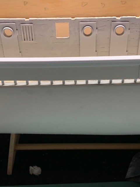
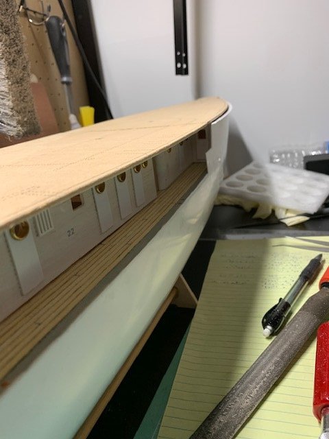
Got a little bit done on the Calypso over the weekend. I created the double doors in the new passageway between the fore and aft cabins as well as created the doors in the forward bulkhead. I started priming the cabin walls and will attempt creating and placing hinges for the doors before painting the cabins. Hopefully by then the temperatures will be warm enough to paint (I'm using rattle cans of Rust-Oleum paint). I also started building the transom and boy that was a chore! Instead of using the 1.8mm x 6mm wooden strips to build the transom I used .080" x .250" styrene strips. I had to glue the first styrene strip in phases by clamping the styrene strip from the rounded end of the hull to the opening of the aft hatch structure. It took 5 phases using superglue but in the end the styrene closely followed the curve of the hull's stern. The second styrene strip acts like a doubler so it was a lot easier to glue down in place using 6 mini clamps to form the curve against first styrene strip. After the glue dried overnight I came back with an x-acto miter saw and trimmed the ends to match the inside edge of the styrene hull. This is when realization hit! I noticed that the starboard railing (part 14) is actually too short! Based on photos this railing is supposed to go all the way to the curve of the stern. The part outline out of the box is about 1/4" too short, so I used scrap styrene sheet to build the additional 1/4" for the railing. So if you build this kit remember to leave the stern end of part 14 longer than the markings show! Tomorrow I plan on sanding the transom and the hull to (hopefully) have the stern's curve blend together using plastic putty (if required). I also started building the little Hughes 300 helicopter to keep myself entertained. I originally wanted to scratch build the cockpit but after a couple of attempts decided to just tint the windows clear blue and be done with it (the thin plastic coupled with a poor fit wore down my patience). Needless to say the fuselage is difficult to glue together and when it was finally glued together after 3 attempts it required a LOT of putty to fill in the gaps! I assembled the helicopter's pontoons and painted both the fuselage and pontoons that famous yellow color. Be warned that I had to put down 5-6 coats of yellow over a light gray primer before the yellow paint looked decent. I'm still not happy with how the paint laid down so I'll probably lay down another coat before beginning to assemble the whole thing together. No photos of the helicopter this time.. too embarrassed on the paint job so maybe next time! I also started building the helipad and boy that also was a chore! The plastic pieces for the helipad frame was warped and broken in a few places. I ended up using a hair dryer to straighten the pieces then gently glued the broken pieces back together. The frame came out "ok" but hey it doesn't need to be perfect as it'll be hidden (for the most part) by the helipad planking (I hope!). I also ordered a right and left hand brass prop from Dumas. I didn't like the plastic prop and so just I had to go with brass props! But after I ordered the props I realized the Calypso probably used 4 bladed props and not 3 bladed props like the one that came in the kit. SIGH! Oh well... I won't tell if you won't! Well that's enough rambling for now. Will post progress photos again hopefully this weekend. More to come! Fuji
- 70 replies
-
- 5
-
-
- calypso
- billing boats
- (and 1 more)
-
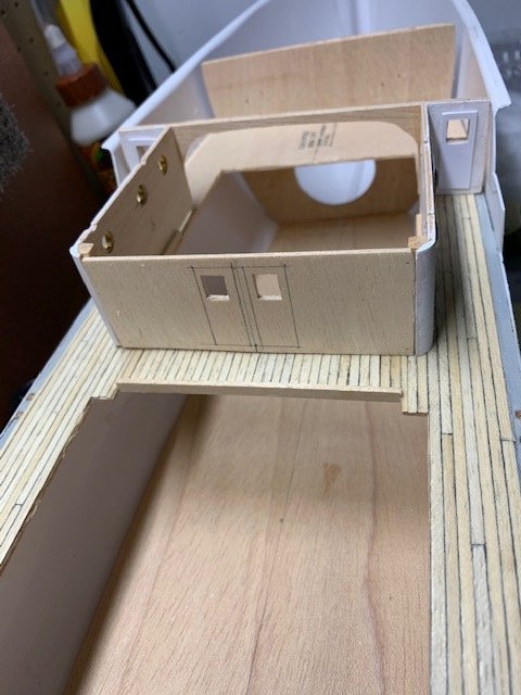
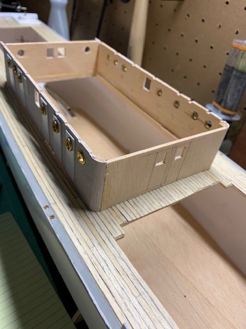
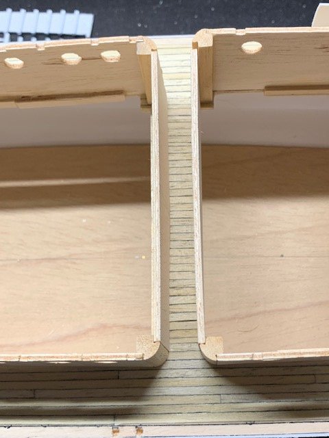
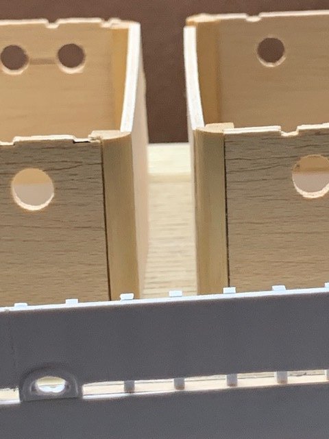
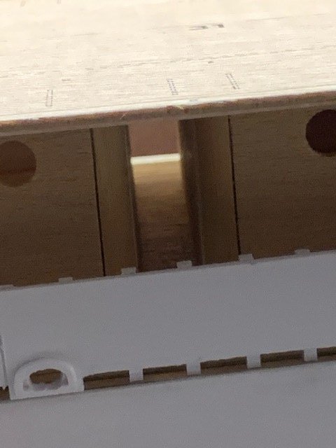
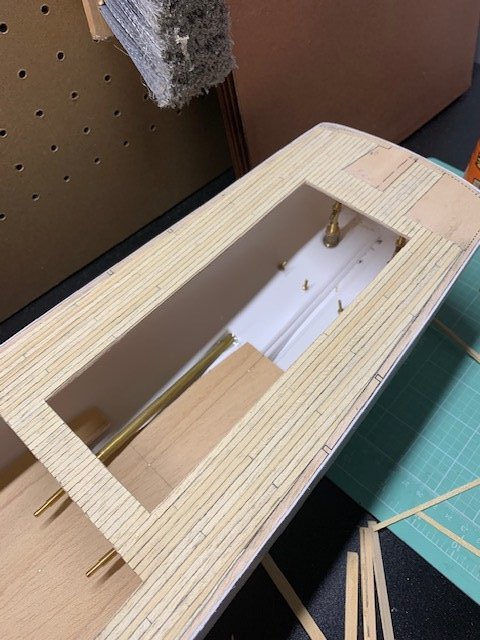
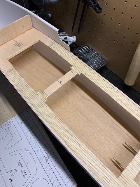
Since it was single digit (and even in the minuses) temperatures over the weekend I was able to get some work done on the Calypso. As I mentioned previously I found that the alcove on the main deck cabins was actually a passageway between the port and starboard sides of the main deck. Since this build is a static display (and because I never make models straight out of the box!) I decided to create the passageway using scrap material from the kit. The first picture is the passageway planking and a dry fit of the scrap built walls. The second picture is a shot farther away so you can see how narrow the passageway is and some orientation to the main cabin walls. The third picture is how this will look with the side railing in place. The final picture is how the passageway will look like with the upper deck in place. I plan on adding double doors in the passageway to each the fore and aft cabins. Since the passageway is so narrow (my guess is about 4 feet wide) I assume the doors into the cabins open INWARD, so I will scribe the doors into the walls with a 6" wide column between the doors and add square windows on each door using the door pattern for the exterior doors. Also note that while watching a Jacques Cousteau's TV shows I noticed that the forward bulkhead which in the model dead ends on the main deck actually has a door with a square window on the starboard side. I assume there is a door with a window on the port side so I will scratch build the two doors using the plastic scrap material and will add them to the forward bulkhead before gluing down the bulkhead to the deck and the forward upper deck to the hull. A note for anyone who is currently building (or will someday build) the Calypso - I discarded the 1.8mm x 2mm wooden sticks which were supposed to be used as the railing supports and used 0.80" x 0.80 Evergreen Styrene strips instead. The wooden sticks were inconsistent in size (and shape), but the styrene strips were uniform and so much easier to cut to length and attach to the railing. It's supposed to be another cold and snowy weekend so more to follow! Miles

- 70 replies
-
- 5
-
-
- calypso
- billing boats
- (and 1 more)
-
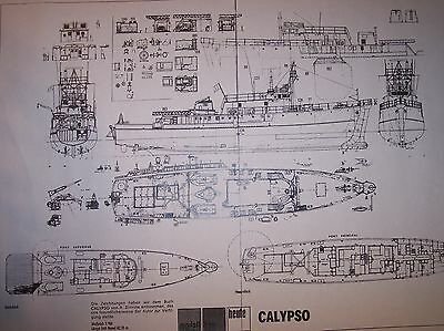
Working slowly on the Calypso build. Started working on the main deck cabins and I became baffled on why there is what appears to be a small alcove between the two main deck cabins. I watched a couple of Jacques Cousteau's shows to see if I could figure out what was actually there. No luck. Then I stumbled across a photo of the Calypso's deck plan and viola! I discovered that what is modeled as an alcove is actually a passageway between the port and starboard side of the main deck! Now this makes sense! So I'm altering the model to add planks all the way between the port and starboard side and actually built the passageway using scrap board which used to be where the aft cabin cutout is on the main deck. Also finished gluing the posts on the port and starboard railings and will start adding the top rail sometime this weekend (it's supposed to snow like the dickens this weekend!). Photo of the deck plan I found (see the lower right plan.. that's the main deck and you'll see the passageway), Photo of the model instructions showing the alcoves, and photo of the dry fit of the forward cabin passageway wall. More to come! Miles


- 70 replies
-
- 3
-
-
- calypso
- billing boats
- (and 1 more)
-
Worked on planking the main deck over the weekend. Bought a pastel pencil and used it to emphasize the edges of the plank. Also used a five plank scheme to define the stagger of the planks and it seems to come out okay. Now only need to lightly sand away any excess glue and give the deck a couple of coats of polyurethane. While planking the deck I decided to cut off the wood pieces which I had previously installed as per the instructions. The wood pieces would have been used to define the inside edge of the structures, but I removed them as I can tell they did not dry perpendicular to the deck. Instead I'm going to glue the wood pieces to the inside of the structure walls once the structures are assembled and painted to help center them to the holes in deck. More to follow! Fuji
- 70 replies
-
- 5
-
-
- calypso
- billing boats
- (and 1 more)
-
Hi Don- Thank you for the insight on how you built your Calypso! Yes you really helped me out with detailing what you did... and also made me realize that I'm not imagining how poorly the fit is between the wooden deck and the ABS hull. I intend to do the same as you by adding the strips. I think that by adding the strips you made your build of the Calypso look very sharp and clean compared to just trying to model it as-is out of the box. I'm currently adding the planks to the main deck and should be ready to post some pictures soon. Thanks again for sharing how you tackled the fit-up issue! Best regards- Miles
- 36 replies
-
- 1
-
-
- calypso
- billing boats
- (and 1 more)
-
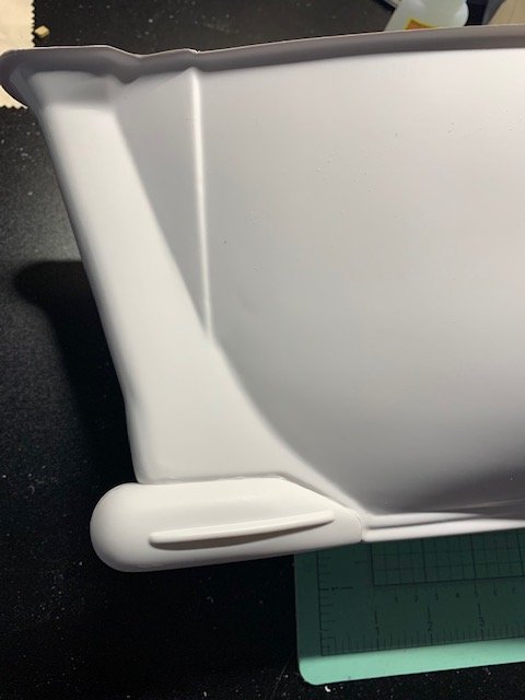
Hello Don- I'm also building Billing Boats' Calypso and couldn't help but notice your beautiful build! The level of detail is fantastic! One of the small details I noticed in your build is the upper deck trim at the hull. It looks as though you modified where the edge of the hull connects to the upper wooden deck. The instructions shows what appears to be forcing (and I do mean forcing!) the ABS hull contour to fit UNDER the wooden deck causing what should be a curved ABS lip under the edge of the wooden deck. I don't care much for that and was trying to figure out a better way to make that work until I saw your build log. Did you use scrap ABS to create that trim to run the entire length of the upper deck? If so, what a great idea to hide what would be an unsightly seam which the instructions would have the modeler make. Thank you in advance! Fuji
-
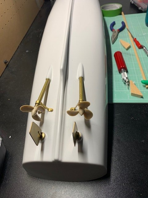
Hello Yves Thank you for your comment! I also thought that the angle of the propeller shaft was too steep of an angle, but I rechecked the centerline of the shaft guide vs. hull penetration angle before epoxying it all together and it is pretty close to the section view provided. I believe the issue is incorrect forming of the prefabricated shaft guide. It could have been corrected by spreading the location holes for where the shaft guide attaches to the hull (and thereby decreasing the shaft angle), but since this model is intended to be a static display I decided to just build it as directed out of the box. Of course now I'll always direct my eye there! LOL! For those also intending to make this build as a static model be aware that the platform intended for the RC receiver and servos and the motors still needs to be installed as a forward bulkhead is attached to the platform. Another word of caution is to try and get this platform as level as possible to avoid a lot of trimming and sanding of the forward bulkhead as it will eventually be used to support the forward deck. Working on the main deck now! More to follow! Fuji
- 70 replies
-
- 2
-
-
- calypso
- billing boats
- (and 1 more)
-
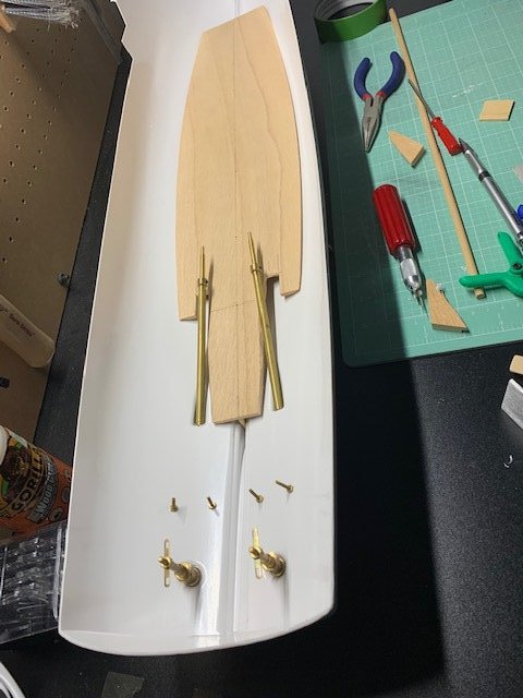
Happy New Year all! I hope all of you survived 2020! All I can say is what a wild ride 2020 was and I hope 2021 is going to be much better. I had set aside my build for a few months. I got really frustrated with this build as the instructions are pretty light to say the least. The straw that broke the camel's back was trying to figure out how to attach the propeller shaft guides to the hull. NO part numbers shown. NO illustration provided. Just a diagram saying to drill two holes 2mm in diameter 58mm from the shaft exit hole in the hull and 8mm and 24mm from the base of the keel. Well I was surfing the internet the other day and came across a journal of this same build and viola! The builder showed pictures of the mounted shaft guides! I looked through the part blister packs and lo and behold there were 4 small bolts with nuts! And ONLY 4 bolts and nuts in the entire set of blister packs. So I guess I could have guessed what the bolts and nuts were for, but maybe I was just frustrated to begin with, with all this COVID-19 stuff, that I just needed to step way for a bit. So here are some progress photos of the Calypso! I still need to clean up some of the messy epoxy work but so far so good! To be continued...
- 70 replies
-
- 3
-
-
- calypso
- billing boats
- (and 1 more)
-
Hi Yves- Yes! Fortunately my wife has a Cricut which can be used to cut just about any shape from a thin acetate sheet! Just need to find a propeller shape and scale it (wwaayyyy) down to fit inside the tube!
- 70 replies
-
- 4
-
-
- calypso
- billing boats
- (and 1 more)
-
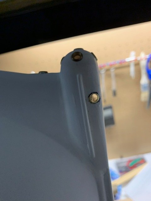
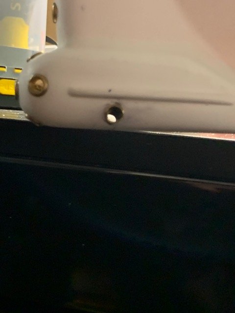
Day 6 Progress Photo! I'm glad I used a copper tube to depict the bow thruster as it is very easy to file down to match the contour of the underwater observation chamber! Literally took 10 minutes using a set of micro rasp files to get the shape I wanted! BTW - The bow thruster is a bit forward of where the photos show as I used the bow of the hull as my reference point. The copper tube actually touches but does not go through the bow. That took drilling a small pilot hole to find where the bow actually is inside of the observation chamber and adjusting accordingly. Now it's time to sand down all my seams and glue blobs on the underwater observation chamber to prep for a quick primer coat to check for irregularities before moving on to drill the holes for the propeller shafts and rudders! Speaking of... does anyone know why we are asked to drill holes for the shaft guide shown in Step 1? The instruction manual and parts list do not indicate we are supposed to add bolts and nuts to install the shaft guides so why drill the holes? I'm tempted to just mark the points shown in the instruction manual and align the holes of the shaft guide to epoxy in place. The days here in Illinois are starting to get cooler, so I think I'll be working a lot more on this build in the upcoming months!
- 70 replies
-
- 4
-
-
- calypso
- billing boats
- (and 1 more)
-
Day 5 Progress Photo! Got back to the build today! I installed the observation port on the bow AND I figured out a way to add the infamous bow thruster! Found some 3/16" diameter copper tubing and viola! it was the perfect size! Drilled through the underwater observation chamber as close to where I believe the thrusters are based on the photos found on the internet and cut the tubing to length. Next I'm going to file/shape the tubing to match the profile of the underwater observation chamber. Once that's done I'll ask the wife to cut a propeller shape out of thin acetate that will be small enough to fit in the tube using her Cricut and will paint and install it to mimic the maneuvering thruster (nothing fancy!).
- 70 replies
-
- 5
-
-
- calypso
- billing boats
- (and 1 more)
-
Thank you Don! This build is certainly one that has been a lot of fun so far! Fuji
- 70 replies
-
- 3
-
-
- calypso
- billing boats
- (and 1 more)
-
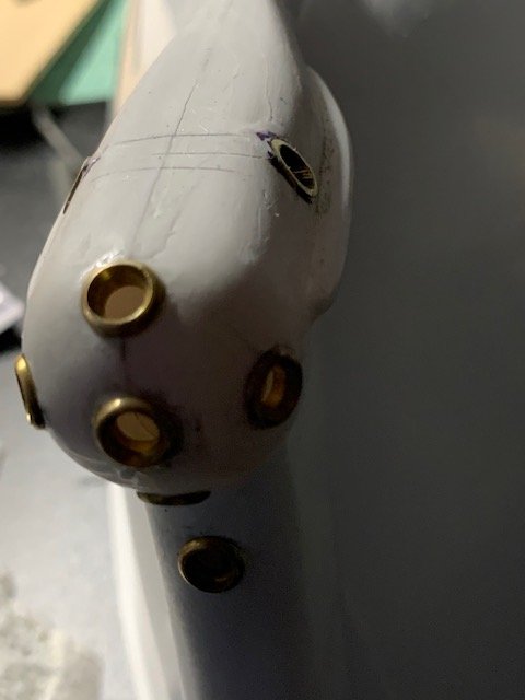
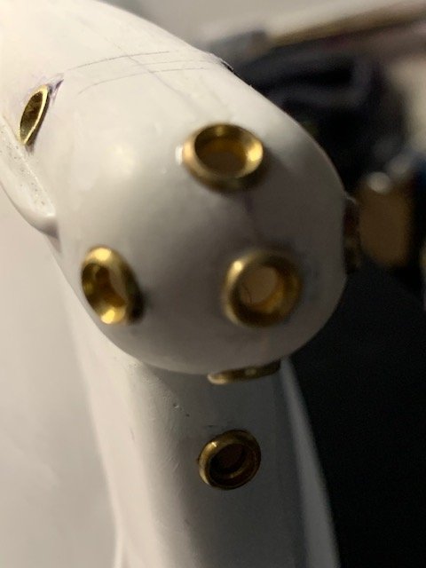
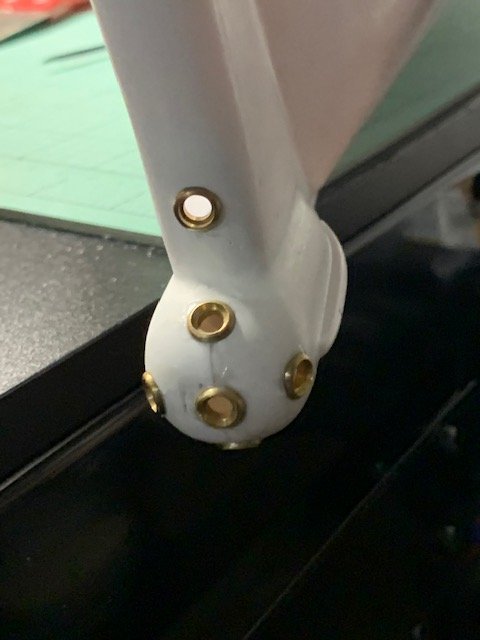
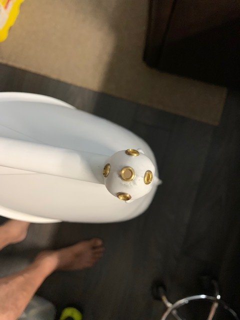
Day 4 Progress Photo! Spent the day drilling the holes for the Underwater Observation Chamber portholes! Measured the hole locations twice then drilled a 1/16" pilot hole. Was expecting the holes drilled on the seam for the upper, lower, and center porthole to split the glued seam so I wasn't surprised when that happened! Once I was happy with the pilot hole placements I drilled a 3/16" hole using the REVERSE direction of my drill to minimize the grab of the drill bit. Once those holes were drilled I used a micro round file to file off the excess ABS plastic until the brass porthole frame fit snugly into the hole(s). It took quite a bit of fitting and filing but I'm happy with the results! I still need to add the porthole just above the underwater observation chamber but I'm saving that for another day. The weather here in Illinois is nice right now and the great outdoors is calling me! P.S. Looking at the modeled underwater observation chamber and the pictures of the bow thruster I can see that adding the bow thruster will require me to remove the horizontal "vanes" along the side of the chamber and remodel the vanes about 3/16" higher. Not too sure if that is a good move or not. Need to think on this one as it'll require quite a bit of surgical cutting and patch work but knowing me if I don't do this I'll always look at the model and think "I should have..." More to come! Fuji

- 70 replies
-
- 8
-
-
- calypso
- billing boats
- (and 1 more)
-
Day 3 Progress Photo! After cutting, sanding, filing, sanding some more (and yes a little cussing!) I finally attached the underwater observation chamber to the bow! The gluing of the two halves of the chamber was a little difficult (or maybe I made it more difficult!) as I glued them together before attaching the chamber as a single unit to the hull. The fit wasn't as smooth or easy as I thought it should be. I ended up using a dowel wrapped in fine grit sandpaper to sand the opening where it attaches to the hull until getting a satisfactory fit. I'm going to let the glue dry for a couple of days then will fill in the visible gaps. I'm thinking about using Bond-o as it does adhere to plastic and will not crack once dried. Once I get the gaps filled and sanded I'm going to attempt to add the observation portholes and (gulp!) the bow thrusters! More to come! Fuji
- 70 replies
-
- 3
-
-
- calypso
- billing boats
- (and 1 more)
-
I did a bit of research and found specifications for what used to be the Hughes 300C helicopter. I'm thinking about scratch building new main and tail rotors using the excess ABS cut away from the hull to scale based on the attached specifications. Fuji Hughes 300C.pdf
-
Hi Bob- This will be a static model. I've already decided this will be a new family heirloom! LOL! Fuji
- 70 replies
-
- 2
-
-
- calypso
- billing boats
- (and 1 more)
-
Hi Bob- Yes I agree! Since this is going to be a once-in-a-lifetime model for me I want to make it as accurate as possible! Fuji
- 70 replies
-
- 3
-
-
- calypso
- billing boats
- (and 1 more)
-
So I've started looking ahead and noticed the diving saucer included in this kit is lacking some detail. Fortunately in my "past life" I used to build models while working at an worldwide engineering company. So when I noticed the model version of the diving saucers excludes the maneuvering nozzles I immediately thought of using insulated solid wire and tapering the end of the wire to mimic the jet nozzle. Sounds easy peasy but the truth will be in the modeling when I get there! Fuji
- 70 replies
-
- 2
-
-
- calypso
- billing boats
- (and 1 more)
-
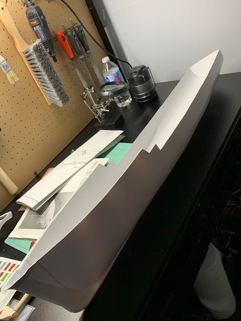
Day 2 progress photo! I've completed trimming the ABS hull and am in the process of sanding down the imperfections. Since the instructions shows to leave 3mm from the outside of the hull to the edge of the trimmed ABS for the upper-fore portion of the hull I decided to just score along the "corner" of the excess trim and remove the ABS above the score line. As the saying goes... "Measure twice... cut once!" or in my case "Better to undercut and sand later than overcut and fill later!" Having fun so far! Thank you all who will be following along to watch me build the Calypso! Fuji
- 70 replies
-
- 1
-
-
- calypso
- billing boats
- (and 1 more)
-
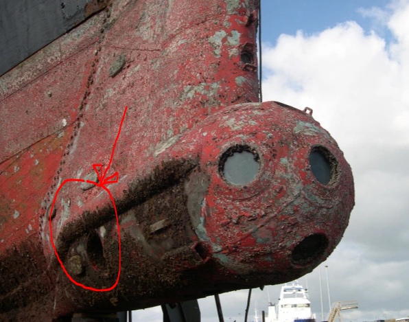
Hi Yves- Thank you for the photos! They are awesome and quite detailed! Based on the photo I believe the port for the bow thruster is just about the same diameter of the "frame" of the underwater observation chamber viewport. I'll have to eyeball it once the observation chamber is installed so I don't undermine the structural integrity of the chamber by making the bow thruster port too large. More to come! Fuji
- 70 replies
-
- 2
-
-
- calypso
- billing boats
- (and 1 more)
-
Hi Yves- Thought about making the Calypso a RC build but decided against it. Thank you for the suggestion though! Fuji
- 70 replies
-
- 1
-
-
- calypso
- billing boats
- (and 1 more)
-
Has anyone noticed the bow thruster on the Calypso and if so, also included the bow thruster on their build of the 1:45 Billing Boats Calypso? I'm researching ways to add it to my build and I have a few ideas, one of which is to drill through the underwater observation chamber and inserting a small diameter PVC tube with a small prop scavenged from another model kit. Would also add a small screen on both sides using aluminum window screen material painted the same tone of red as the hull.
- 70 replies
-
- 2
-
-
- calypso
- billing boats
- (and 1 more)
-
Wow! Beautiful build nunnehi! I'm getting ready to also build the Billing Boats 1:45 scale Calypso and I hope my model will come out half as beautiful as yours! If you don't mind me asking... how did you do the porthole and underwater observation port glass? Did you use thin clear acetate cut to shape and glue from behind or did you use something else? Thank you in advance!