HOLIDAY DONATION DRIVE - SUPPORT MSW - DO YOUR PART TO KEEP THIS GREAT FORUM GOING! (89 donations so far out of 49,000 members - C'mon guys!)
×
xodar461
-
Posts
172 -
Joined
-
Last visited
Content Type
Profiles
Forums
Gallery
Events
Everything posted by xodar461
-
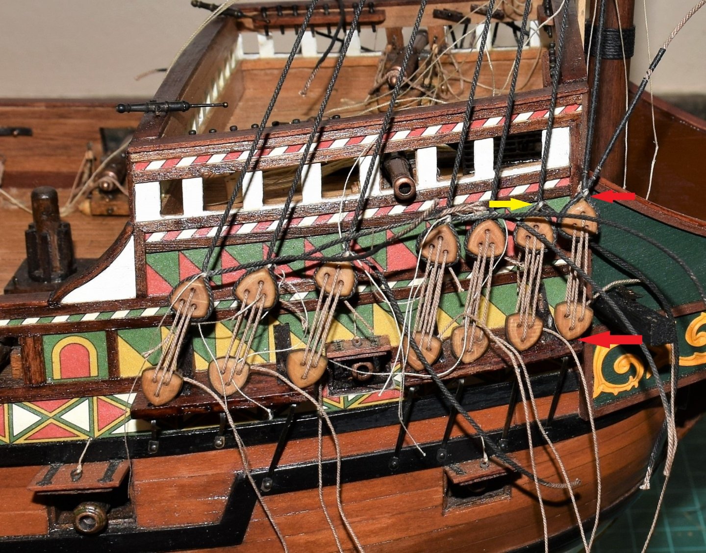
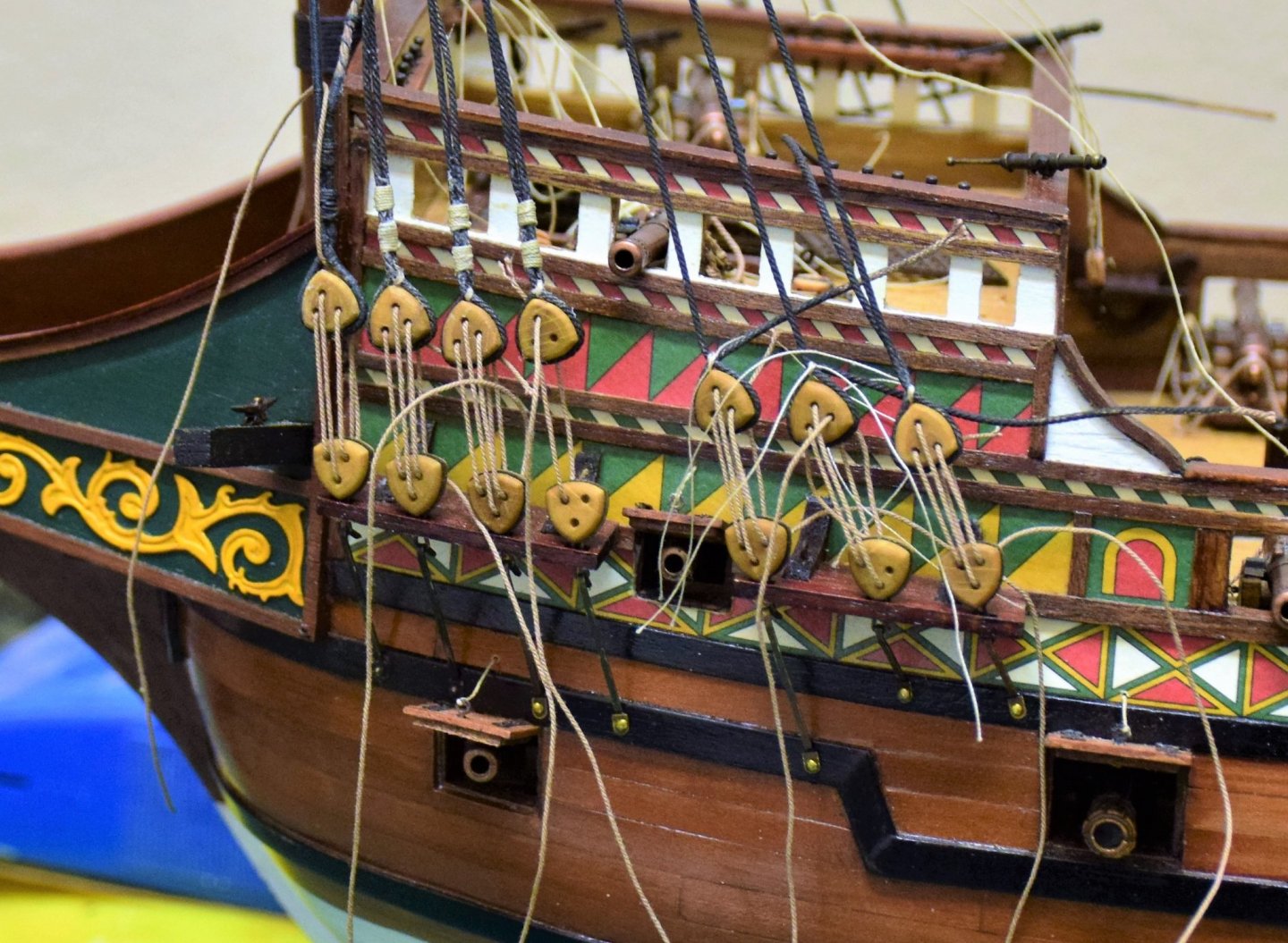
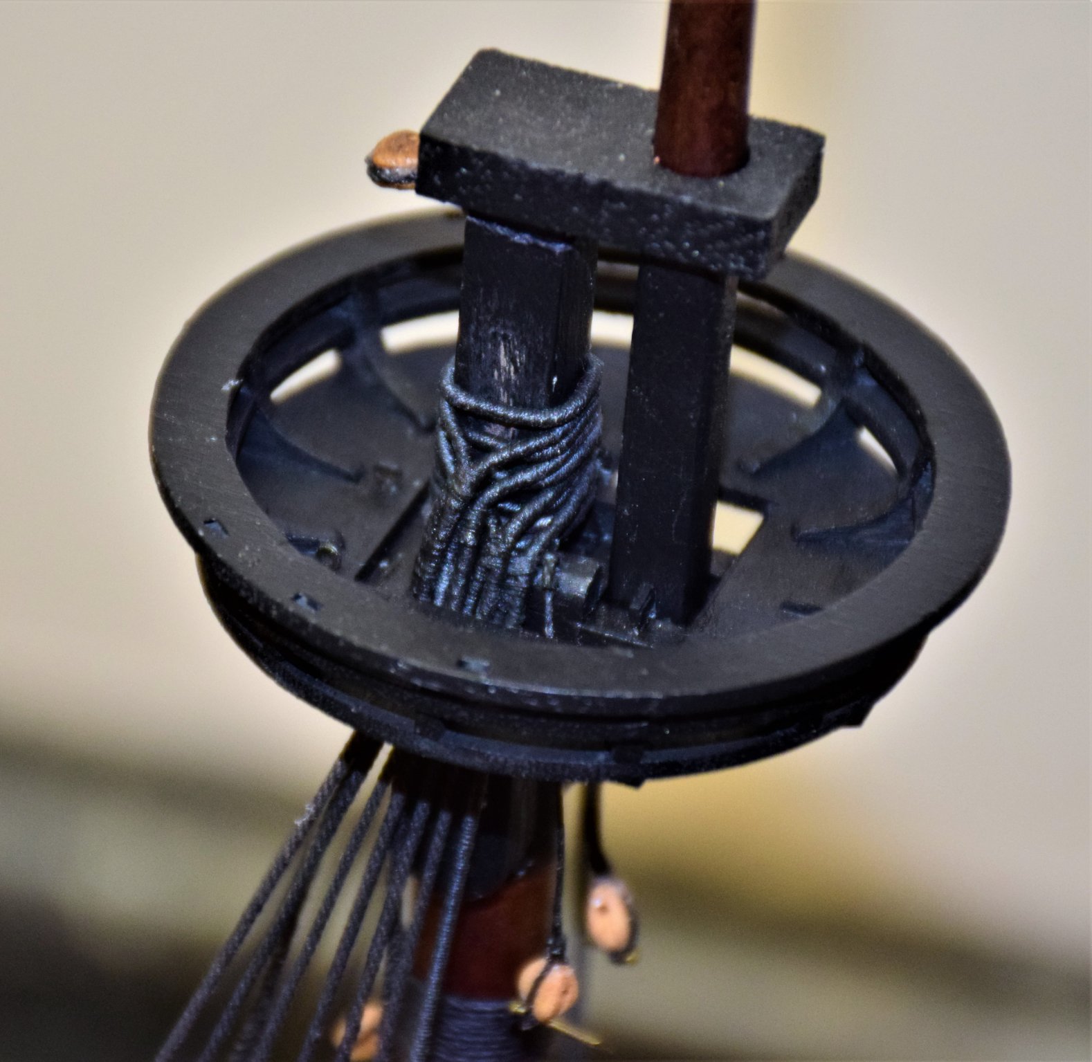
 Greetings! work on the fore shrouds now in progress. The fore-most shroud on the fore and main mast are typically served and the serving tool from Syren has been invaluable The eye of the shroud that goes around the mast is also served. Shrouds are placed in pairs and alternate from side to side starting on the starboard side. Photo below shows a close up of the shrouds at the masthead once the shrouds were placed, work on the deadeyes and and lanyards can begin. Before placing the upper deadeye, the lower ones (which had been stropped earlier with photo-etched brass supplied with the kit and blackened) were placed in the channels. Chain-plates were a single piece of brass that has to be bent at the appropriate place and then secured to the wale with a small brass nail. The shroud (minus the deadeye) was used to determine the correct angle for the chain-plate. Each deadeye was then attached to the shroud initially with just the eye seizing. Note that the shroud loops around the deadeye and crosses in the back with the eventual short end on the forward side of the shroud to starboard and to the aft on the port side. When the correct distance between the deadeyes is determined (usually 2-3 x the deadeye diameter), the lanyards are placed. For me, this takes a lot of back and forth to get the spacing correct before the final seizing is placed on the shrouds. Picture below illustrates some of the principals from above. photo below shows the work in progress. The distance between the red arrows should be the same for each deadeye. The yellow arrow points to the eye seizing. The aft 3 deadeyes are lower than the others because the distance between the deadeyes was originally set up to low. As just the eye seizing was placed, it was fairly simple to adjust the distance. As you can see, there is quite a tangle of ropes as I left the extra on the eye seizing, lanyards and shrouds. Nothing is trimmed until I am ready to finalize things. Like Jonathan (also building Revenge), I found that the nails holding the chainplates were coming out a bit so the were all fixed with a drop of CA. Photo below shows some shroud seizing placed on the port side. The first 3 lanyards are set with the rope going through the eye. The aft 3 still need to be adjusted to the correct height. Another issue that came up: as I put tension on the lanyards, the channel support started to, ever so sightly, pull away from the hull. To fix this, the forward most ones which had pulled away slightly were re-glued and then fixed with a dowel through the support into the hull. I did this to all the channel supports to prevent this with future shrouds. With the deadeye distance complete, the shrouds were then seized (2 seizings on each) and the lanyards seized. End result is below. The aft 2 chainplates seem to be at the wrong angle but i suspect this is from the camera angle as the second photo shows them in a better position. With the fore shrouds now complete, work on the Futtock shrouds, catharpins and ratline will be next. Jeff


.thumb.JPG.9c1b590a39a51bdf2aa60afdc8a59ac5.JPG)
-
Reducing mast circumference without a lathe
xodar461 replied to Charlie pal's topic in Masting, rigging and sails
As with the post above, I use a standard hand held drill. it is easy to do for mast - just stick one end in the drill and sand to desired thickness. I like to leave the dowel long to account for the part that is in the drill chuck as the chuck will leave indentations on the wood. This can be sawed off later. I do yards with a drill as well but with some modification as both ends need to be tapered, unlike the mast. The yard is cut longer than needed (again to account for the part of the yard in the chuck. Once one side is sanded then the other side will need to be cut to the correct length. Then I wrap some painters tape around the side that has been tapered (so the tape rather than the wood with get the indentations from the chuck) and you are ready to sand the other side. This method has worked well for me over the years. Some yards recently done can be see on my log of the revenge by xodar461 Jeff -
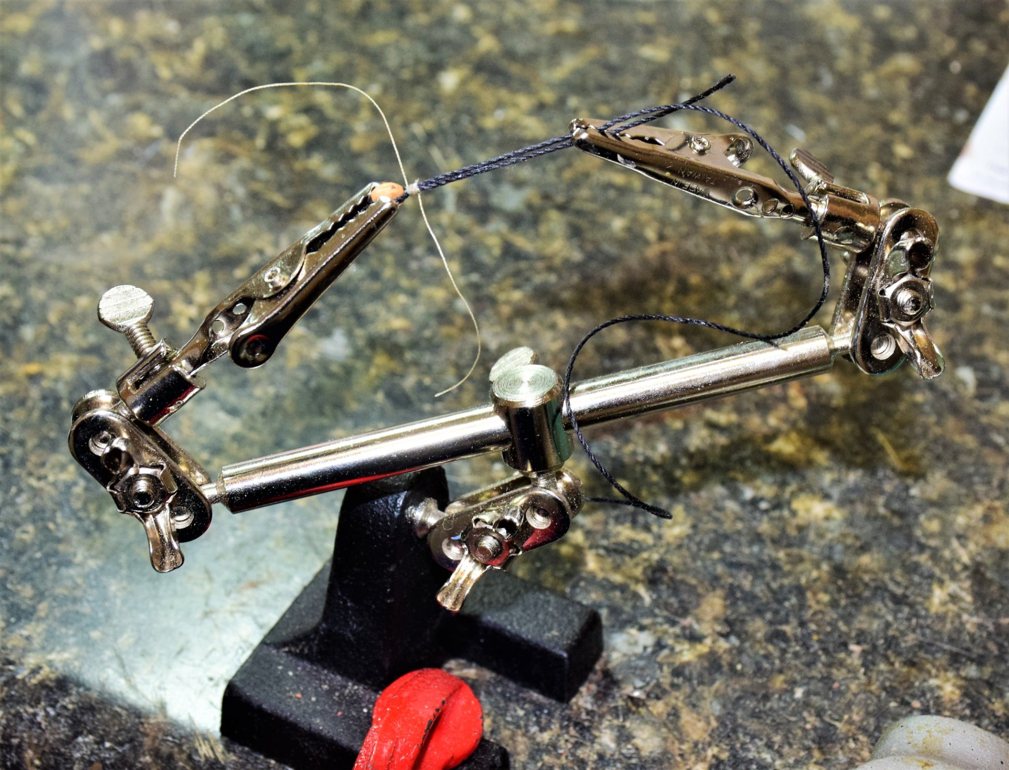
Greetings The masts and yards are now complete with all necessary blocks attached. The first lines have been placed...the main tackles. The falls are not yet cut as I like to leave the extra on in case lines need to be adjusted later. The rope coils will be added to the belaying pins when the lines are cut. The tool below is quite useful for seizing blocks. Shrouds and ratlines come after the tackles. I'll try to post some pics as they are completed Jeff


-
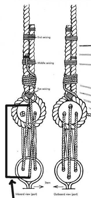
Hi Jonathan: I would check the orientation of your blocks. the ones seen on the first photo above seem to be upside down...the "holes" in the block (meant to represent the opening for the rope to pass over the pulley inside the block) should be oriented so that it is closest to where the block is seized. This photo below (though not very good) illustrates this. The blue line is the block strop, the black is the seizing (the "blue" rope above the seizing will be what gets tied around the yard) and the red is the line that passes through the block. I am not a big fan of the blocks supplied by the kit as they are too boxy. There are several retailers that sell very accurate blocks albeit at a price (check out Syren Ship Model Co listed on homepage here), but I think they will greatly add to the overall appearance of your model. I would also consider not placing the yards on the masts until most of the standing rigging is done. I think you may find the yards get in the way at this point Jeff
_LI.jpg.071a3d80b043a4422b88c5cc4d7ce71c.jpg)
-
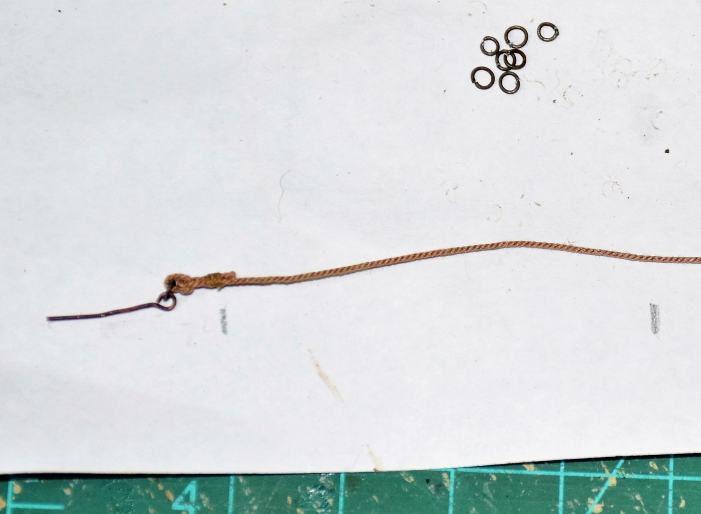
I am currently building the 1577 Revenge ( Amati) and I was wondering if anyone can help with a question regarding when serving of ropes that go around the masthead (and the forward most shroud) began. Only reference I could find was in in zu Mondfeld's Historic Ship Models where he states that the foremost shroud on each mast was "wormed parcelled and served from the first half of the sixteenth century on" and from the middle of the sixteenth century on, the eye round the masthead was also served. The ship's scale is big enough that it won't be a problem to do it and it would make a noticeable difference when compared to the part of the shroud that in not served. Any thoughts would be appreciated Jeff (Revenge build log under Xodar461)
- 1 reply
-
- 1
-

-
Hi Jonathan. Looking good. I recommend putting all the blocks on the yards before mounting them. The mizzen and bonaventure yards don't have many blocks so it should not be a problem putting them on with the yards already attached, however it may be a problem with the main and fore yards as they have many more blocks (8-10 on each yard). Jeff
-
The parrels look good to me The brand of paint I use is called model masters by Testors. I got it at Hobby Lobby. Jeff

-
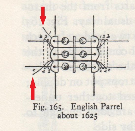
Hi Jonathan: re paint: I use flat black acrylic - easy to apply with brush and clean up with water. I good finish can be obtained with several coats and light sanding in between coats with very fine sandpaper or steel wool. I'll have a few pics soon of the yards on my build. I am almost finished with attaching all the blocks. As far as the parrels, this pic may help. although it is about 50 years ahead of the Revenge, I think it is a good way to attach them to the yards. the 2 loose ends can be simply tied around the yard (red arrows) as it is one continuous line. (photo from "The Rigging of Ships in the Days of the Spritsail Topmast" by RC Anderson) Hope this helps Jeff
-
Jonathan: regarding your question about the relationship of the masts to the decks...the foremast is pretty easy as there is not much depth to the hole it goes through. the profile of the ship (plan 4) shows on what deck the main and mizzen mast sit. The lengths of these 2 masts as shown on the plans is correct and you should have no problem seating these 2 as long as the decks were properly placed. The bonaventure mast needs some adjustment. Plan 4 shows that it sits on the quarter deck however there is an opening on the quarter deck (see first photo page 39) for this mast so it really sits one deck lower (on the rear upper deck). The correct rake of this mast will be obtained by placing the mast through these 2 openings. Therefore this mast needs to be longer than what is found on the plans - just measure the distance between the 2 decks from the profile and add it to the length of the bonaventure mast shown on the plans 9 (~40 mm). To see if you are at the correct depth, insert masts and mark deck line on the mast with a pencil and then compare to plan 4. hope this helps jeff
-
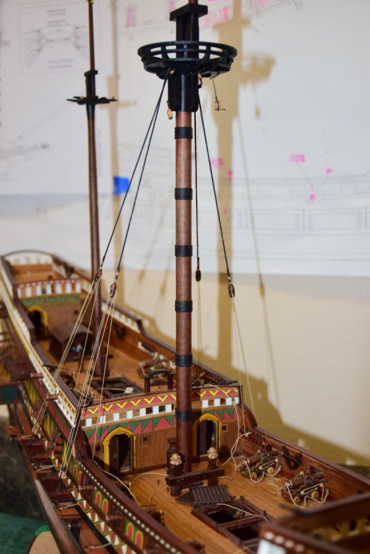
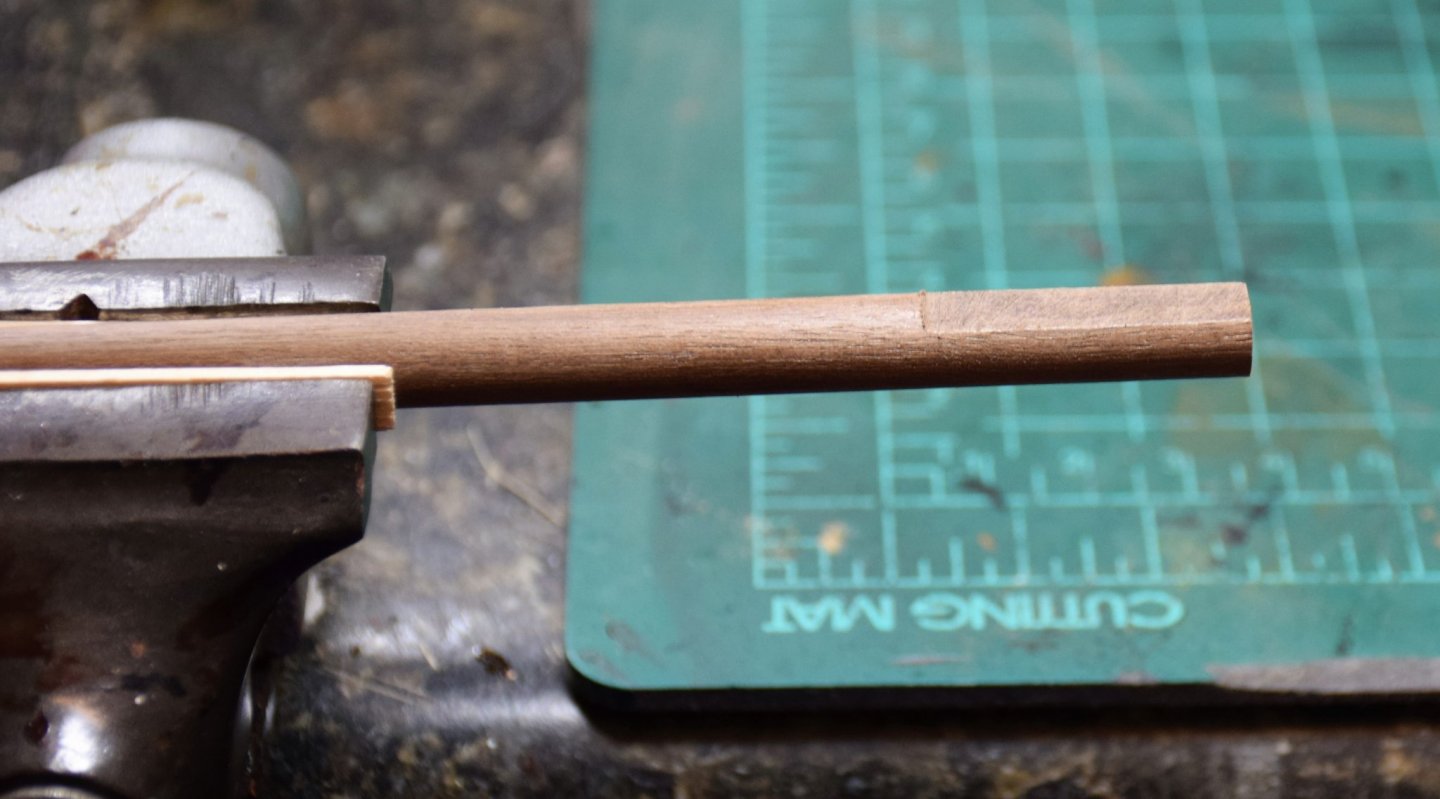
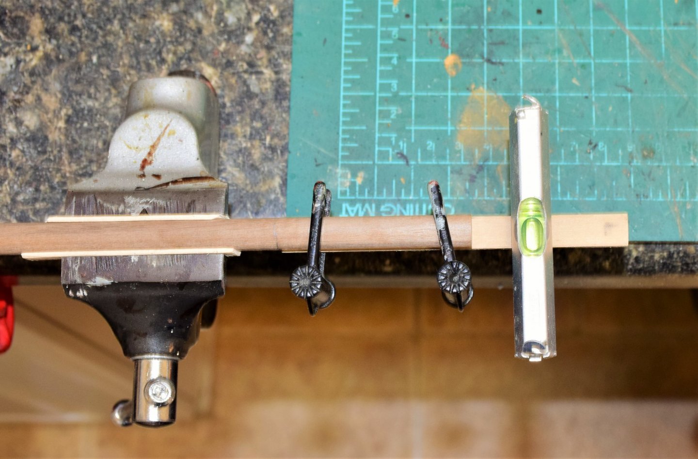
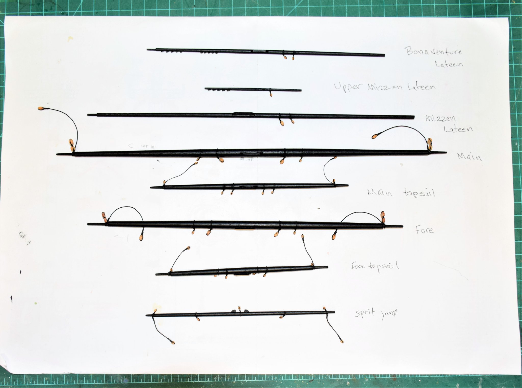
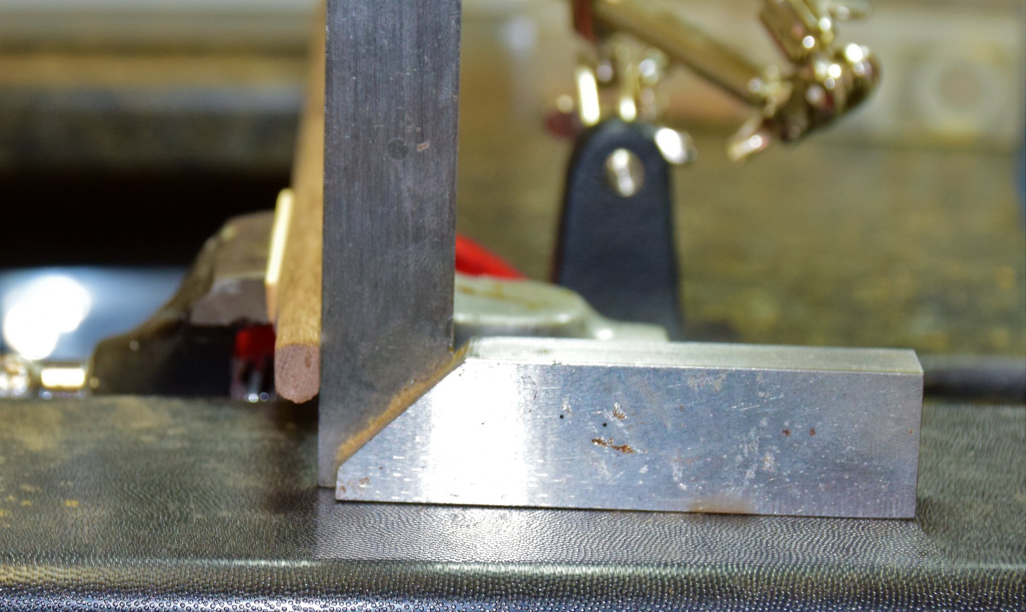
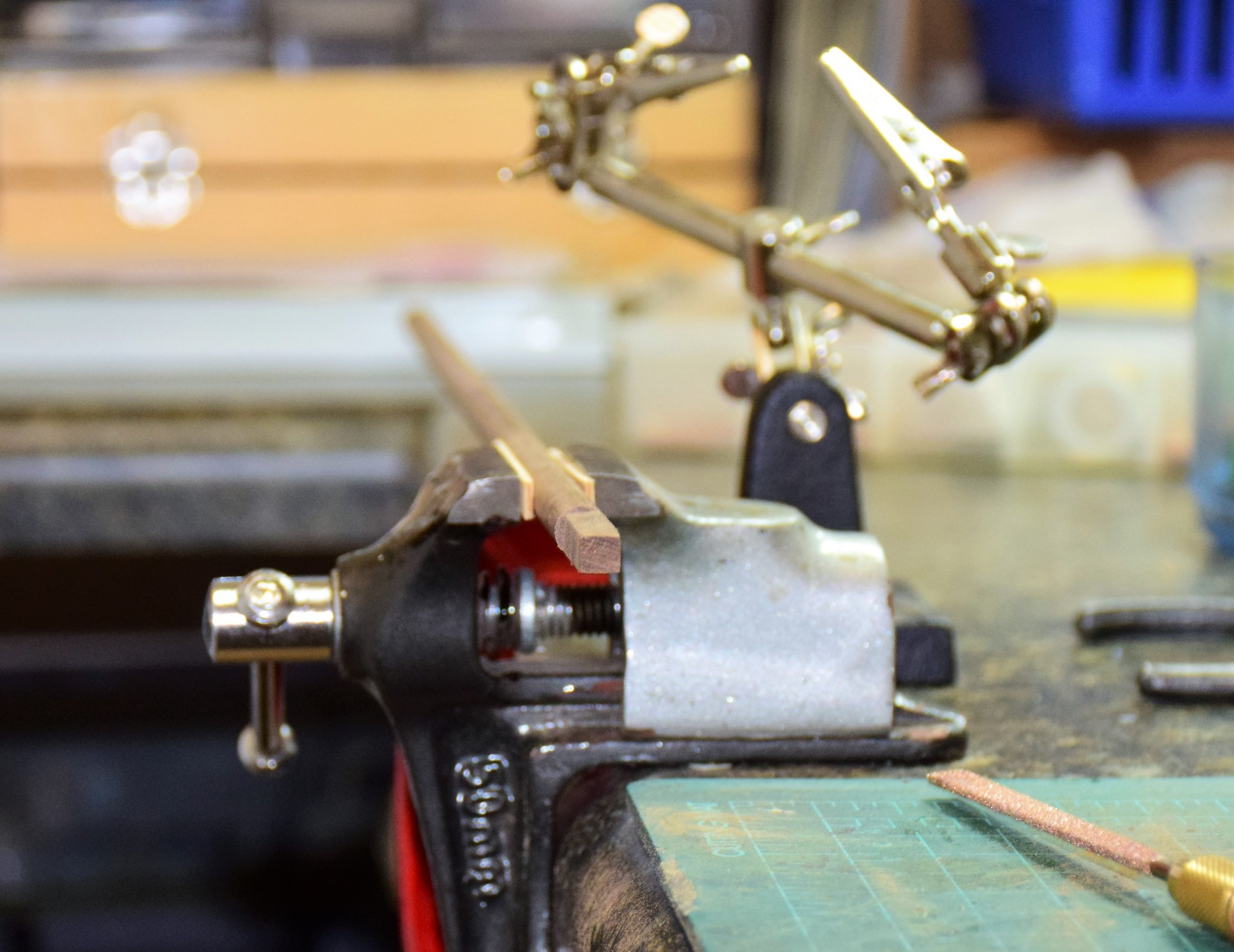
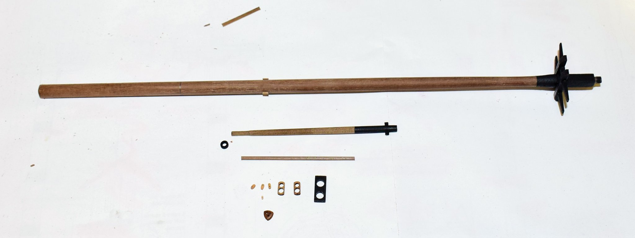
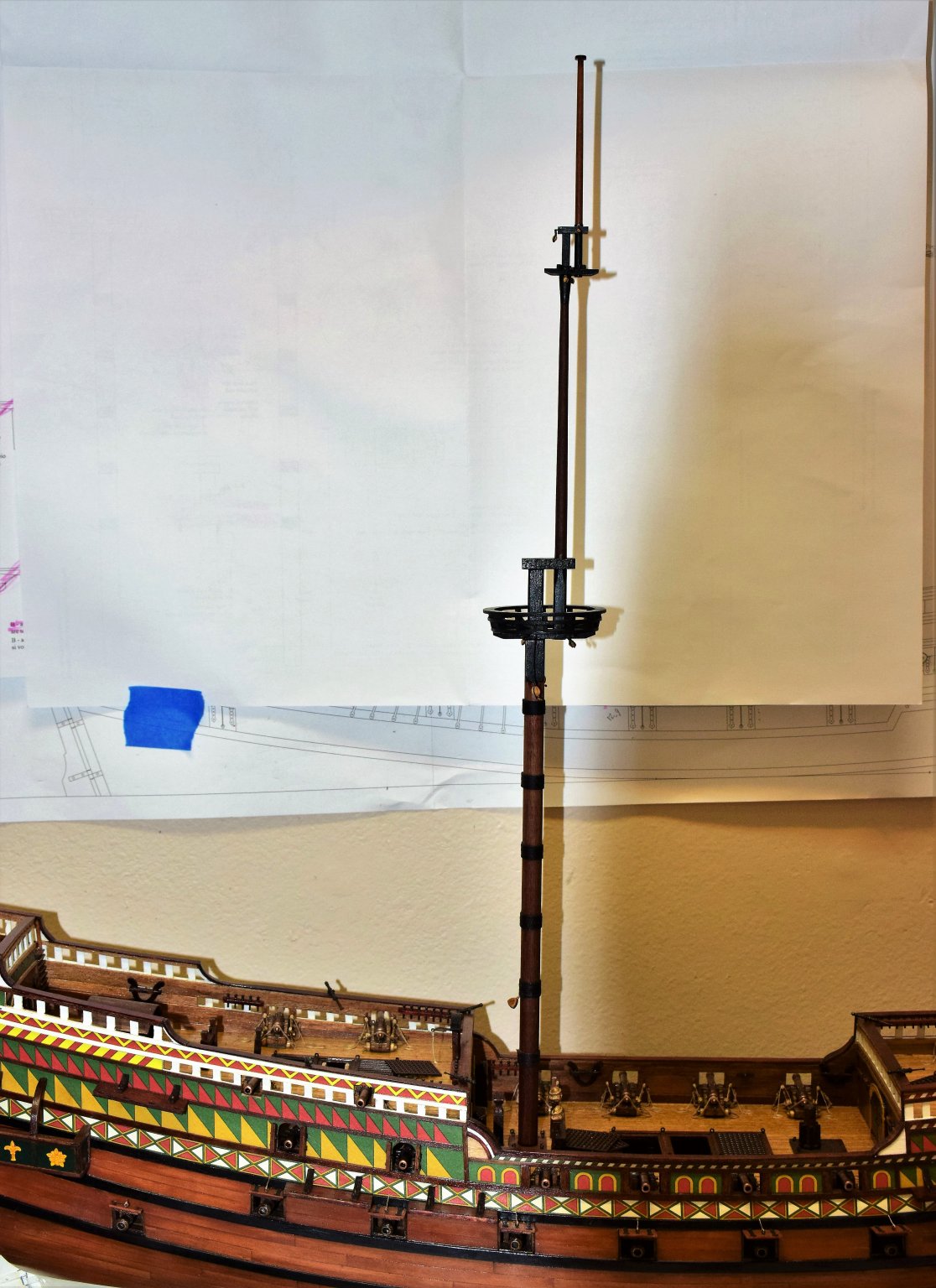
Greetings! I am currently working on masts and yards. here are a few pics... first one shows the components to the main mast including to mainmast, topmast,flagstaff and main yard main top The masts start as round walnut dowels and have a square top ( and bottom for the topmast). Here's how i do it. The dowel in secured in a vise with some scrap wood to protect the mast from getting marked up by the vise. the top is then sanded flat with a file, but only to 1/2 the thickness that will ultimately need to be removed (i.e., the mainmast is a 10 mm dowel and the square part at the top needs to be 7 mm. 1.5 mm needs to be removed in this first step). The dowel is then rotated 180 degrees and filed flat. I used a level to be sure the side filed first was level in order to be sure the 2 sides were roughly parallel. next, the dowel is turned 90 degrees and position is checked with a carpenters square to ensure that the sides already filed are perpendicular. after third side is filed, rotate 180 degrees and repeat. end result should look like this... It can be a bit tricky to do the top mast because the top and bottom are both square. And as to tapering masts and yards, I stick one end in a drill and sand it down to desired thickness. I found that using a plane will often make gouges along the grain and ruin the dowel. when making a yard that has to be tapered on both ends, i use painters tape to protect the side that has been tapered so as not to leave marks from the drill chuck. Below is the mizzen main and topmast and flagstaff along with some of the blocks to be attached. You may notice the small piece of wood at the bottom of the topmast...this is called the fid. it measures 2x1 mm. 2 small holes of 1 mm each are drilled and the opening is cleaned up with a small file. Below...main mast in place, not yet glued. All of the masts and yards with associated blocks will be made prior to the start of any rigging Jeff


-
Hi Jonathan Great job on you ship so far! I would not get too hung up on specific locations for the eyebolts as when the ship is complete and rigged they will hardly be noticed. The main thing is not to have different sizes in one area. As such, I recommend using the larger ones on: 1. the hatch coamings (forecastle, main and quarterdeck - 22 total) 2. main and mizzen mast base (8) 3. last 6 go on the deck near the main base (4) and mizzen base (2) this will use up all 36 large bolts and you will have consistent sizes in the same areas. All other eyebolts illustrated on the overhead diagram (page 76-77 on manual) can be the smaller ones (part 227) Hope this helps. Feel free to send me a message should you have any questions going forward. I am currently making masts and yards for the Revenge Jeff (revenge build log by xodar461)
-
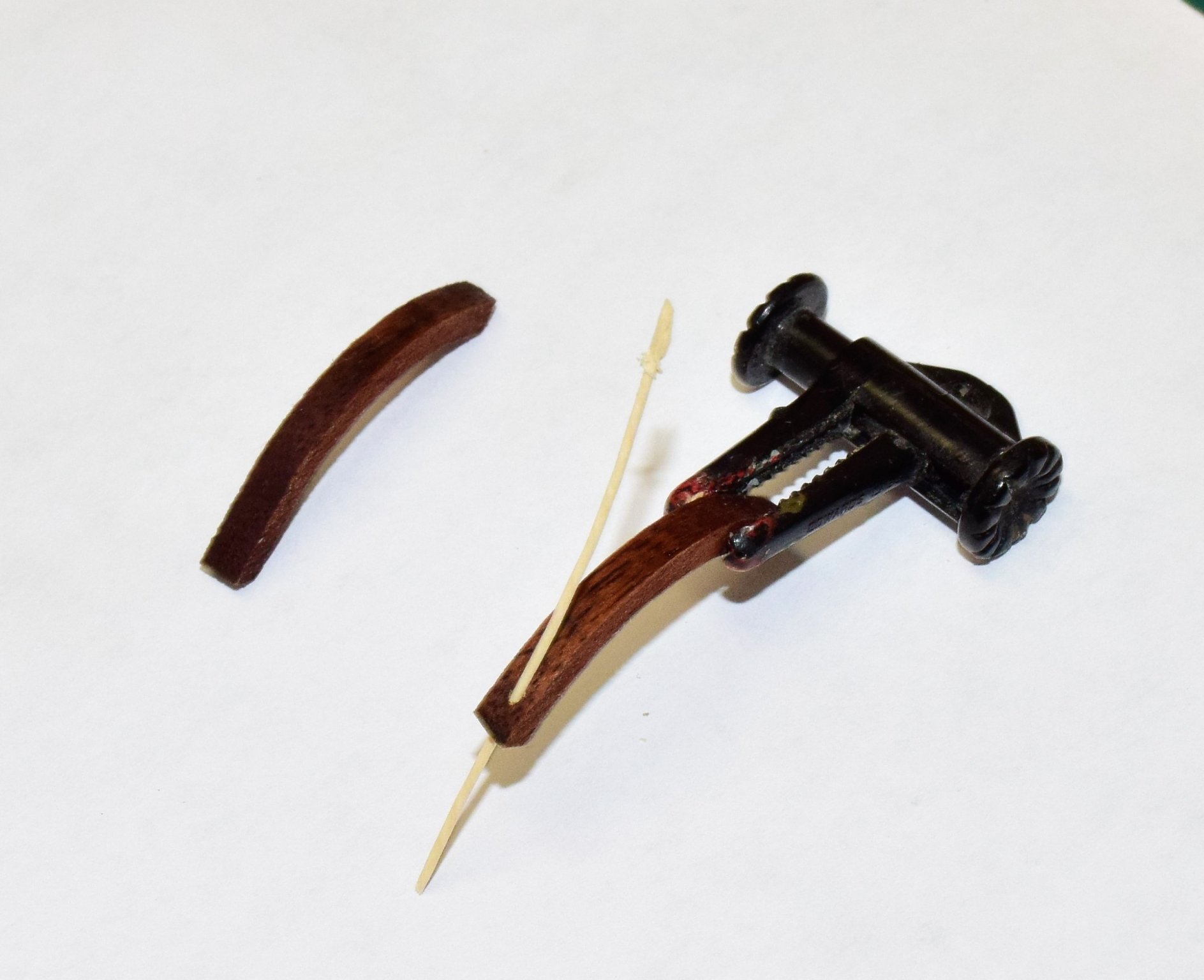
hi Jonathan, I've enjoyed following along with your building log. A few suggestions from a been there, done that perspective...to get a good curve on the 1x2 mm wood strips, soak several strips of the appropriate length in water until they no longer float. then stack them together and clamp to a pot of a diameter that is close to the curve you want and let dry thoroughly. the wood can then be easily worked to the correct curve with minimal stress on the wood. This worked well for me. As for the bow, I snapped mine off early into the build. I did not try to repair until it was time to complete the bow with the support pieces and platform. this will give the repair added strength with the only weak area being the part that just out past the platform (which I almost broke). jeff (revenge build log by xodar461)
-
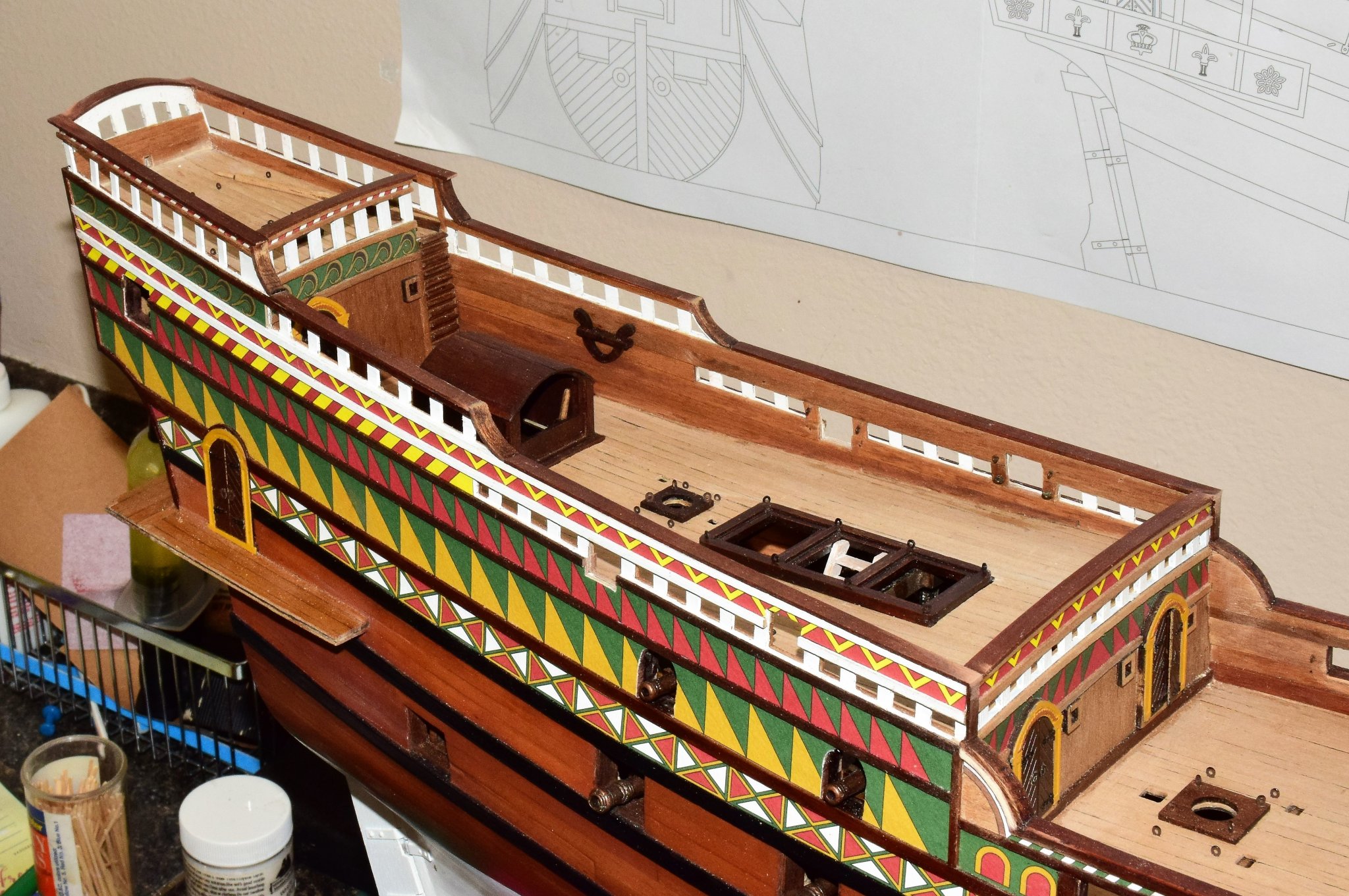
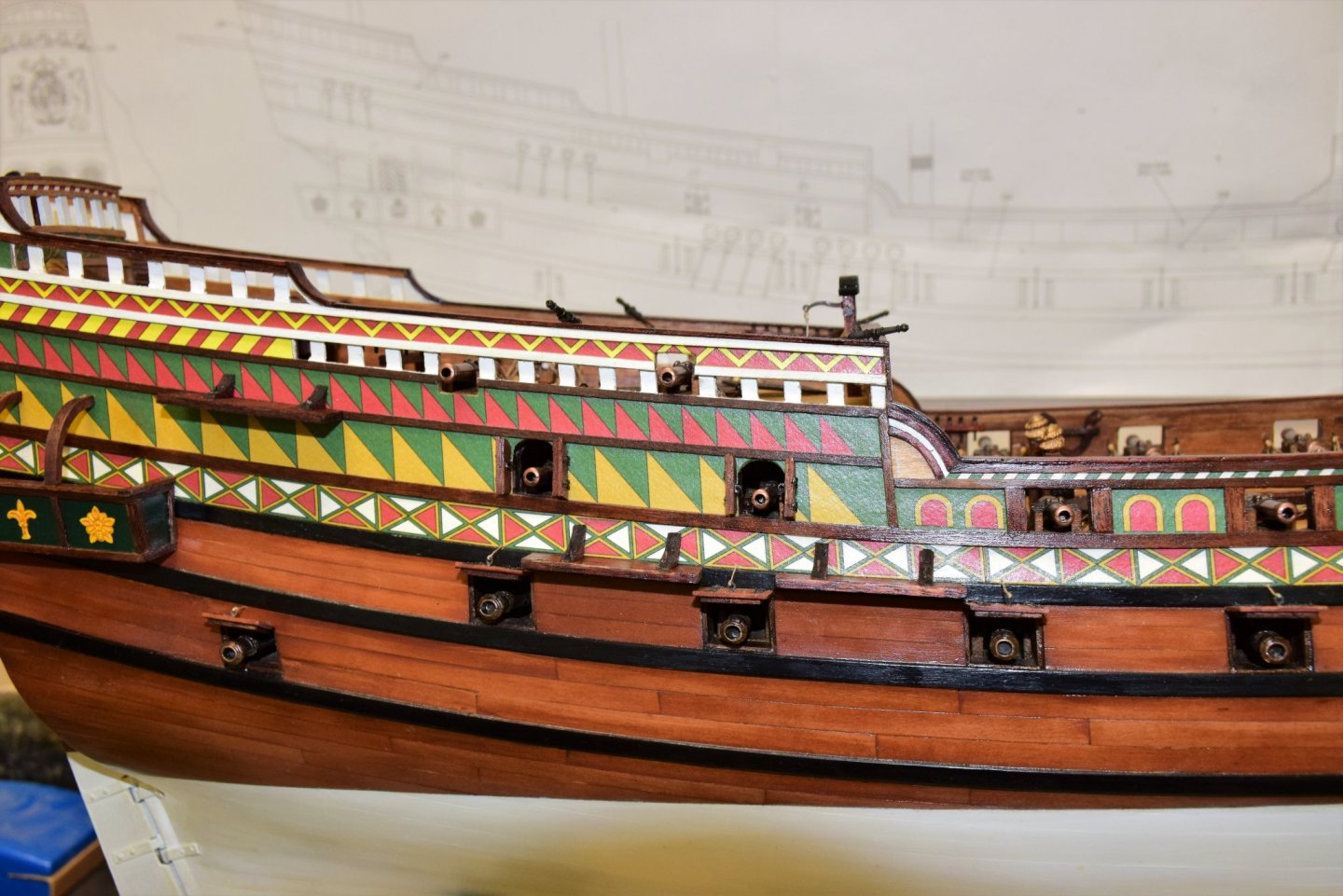
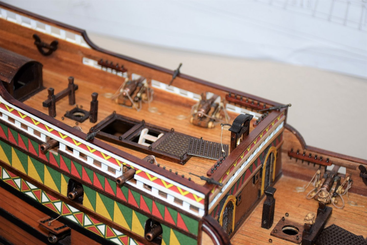
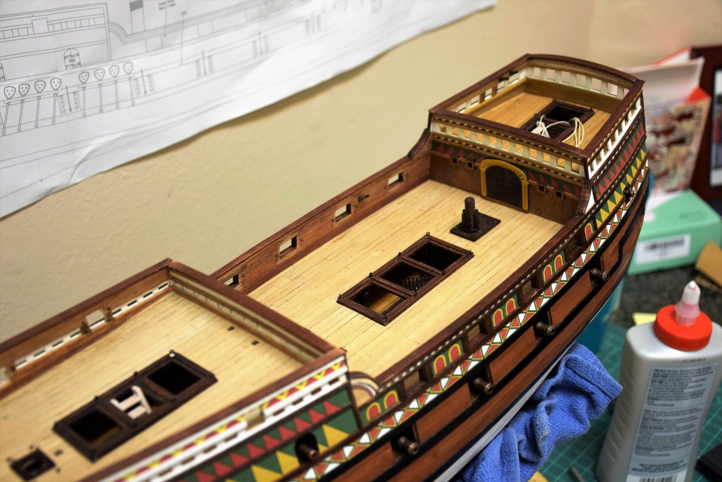
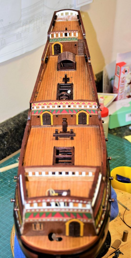
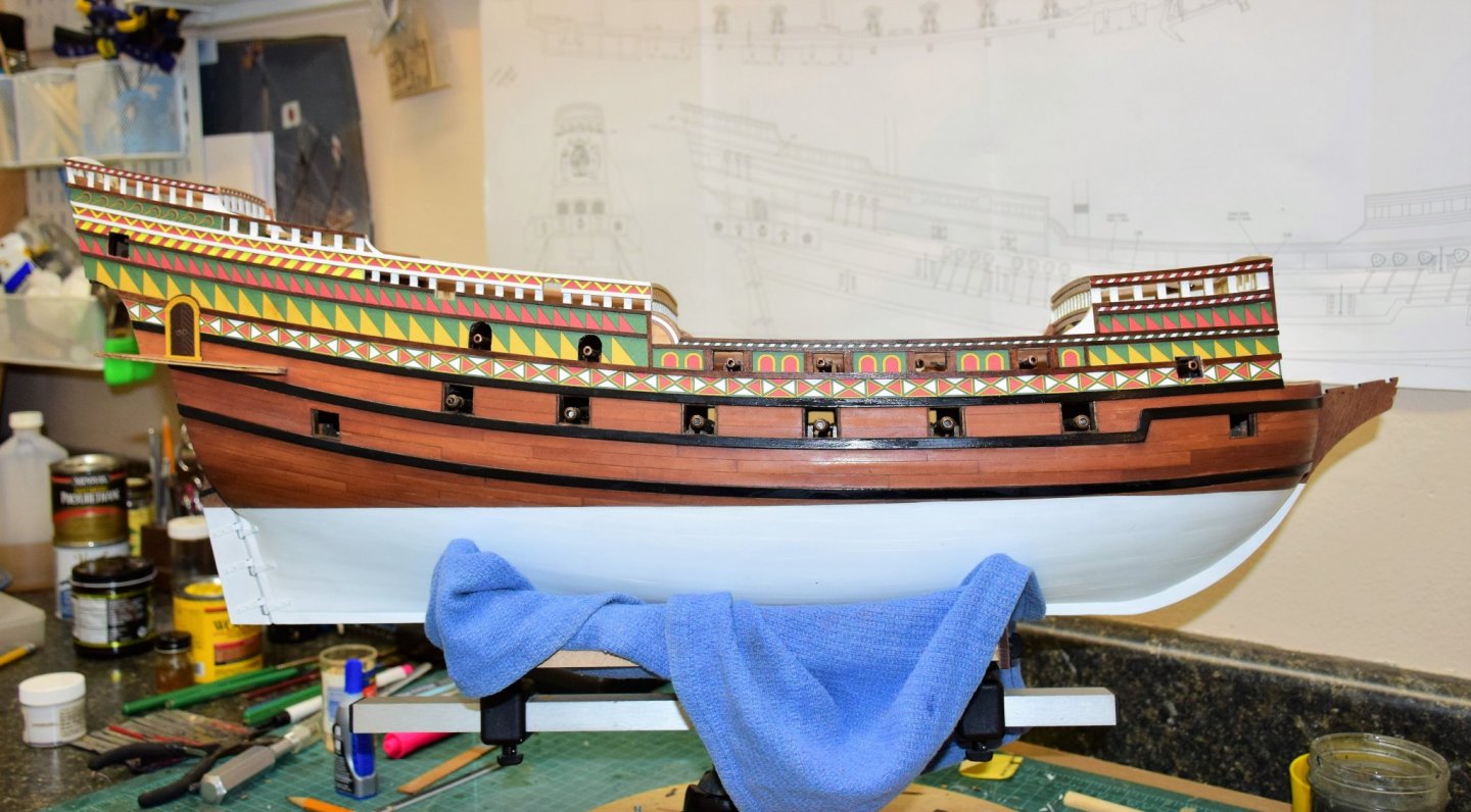
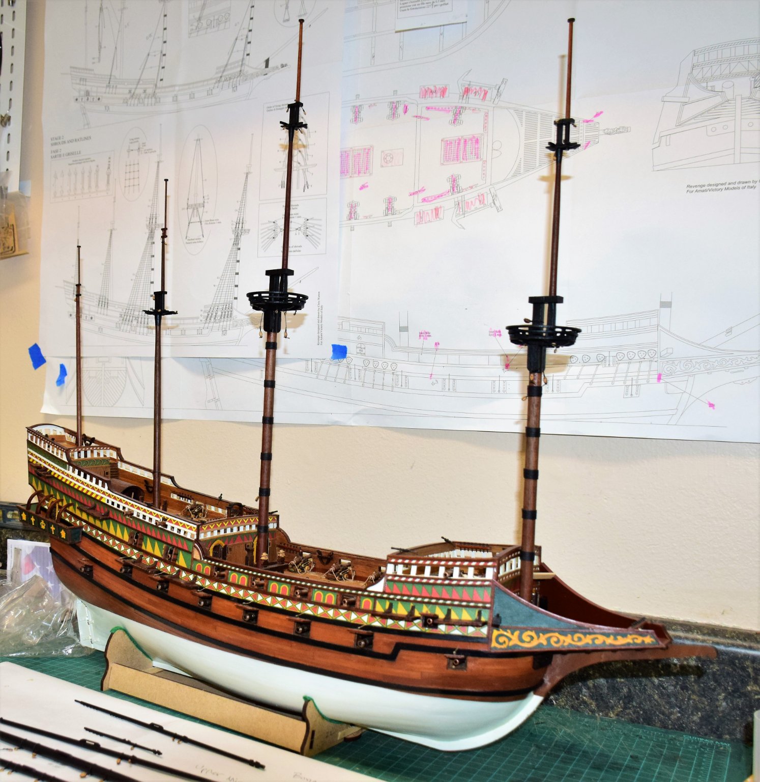
Greetings! Gunports (and corresponding ropes to open them) and deadeye channels have been placed. All pretty straightforward. The channels each have 2 pins that go into the hull to help secure them. Next the curved beams on the port and starboard balcony were placed. Instructions call for a pin to be put on the end of the beam that goes against the hull. To me this presented a possible problem with final placement as the hole in the hull would have to be perfect the first time - no second chances given that these beams are glued against the decorative paper. If they are misaligned, removing them may cause damage to the paper that would be impossible to fix. I modified this by drilling a small hole through the top of the beam and out the end. when the beam is properly positioned and glued, this hole acts as a guide to drill a hole in the hull and then a small wood dowel (0.67 mm) is used to anchor the beam. photos below show this. All in place ... And with this the hull is pretty much complete. It will be put aside while I work on the masts and yards. Jeff

- 159 replies
-
- 10
-
-
Greetings, I am currently constructing the Revenge and I would like to display the ship at anchor in calm seas as she may have been seen of the coast of Spain in the Sea of Cadiz. Modelling water will be a first for me. I have the book "Waterline Dioramas" and the author mentions using textured Plexiglas that would simulate the small swells seen in calm seas. My idea is use a template to to cut the Plexiglas at the waterline - the ship will then sit in the cutout after the Plexiglas is painted. Photo below shows this using a cardboard template (taken from my build log). Here are some options for textured Plexiglas that I've found on the web: I think this may be the easiest way to simulate water and should look pretty good once painted (I hope). Any thoughts or advice? Jeff
.jpg.01ca6044ddeca96ff0ad52e9a93f4742.jpg)
.jpg.4169572fb22f3c0720818fc7037e2b6b.jpg)
-
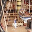
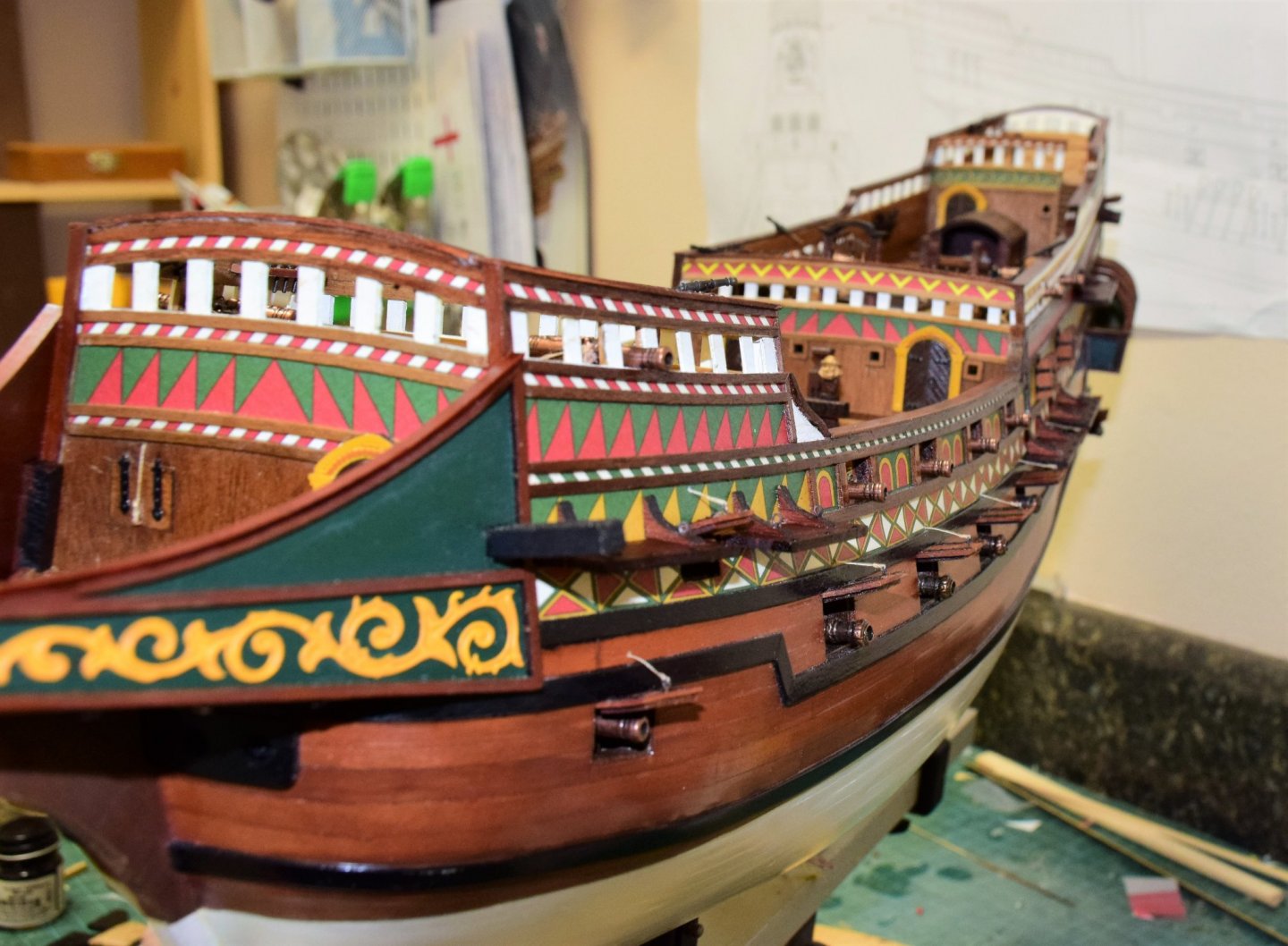
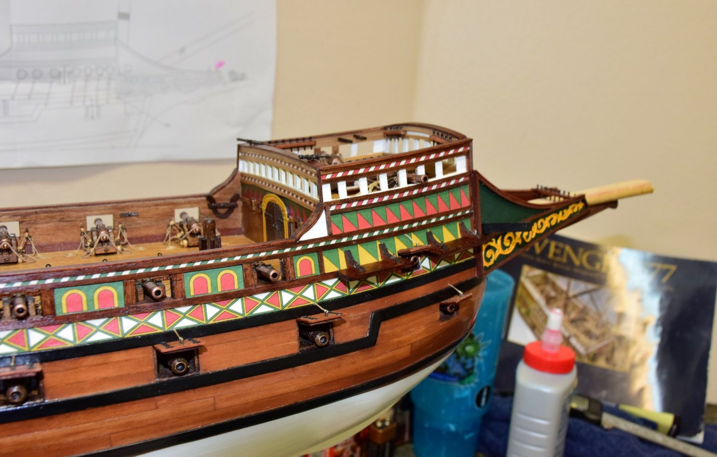
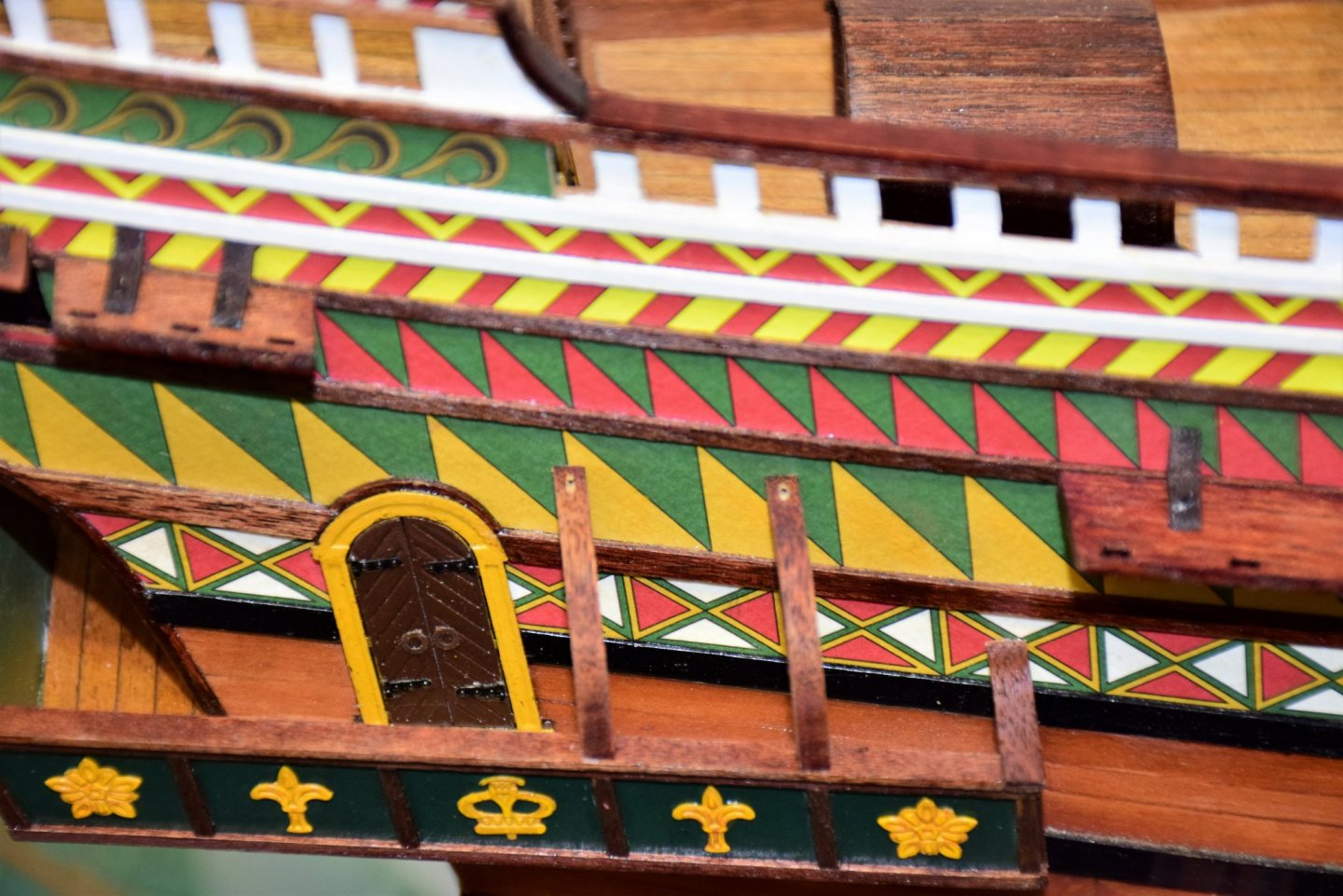
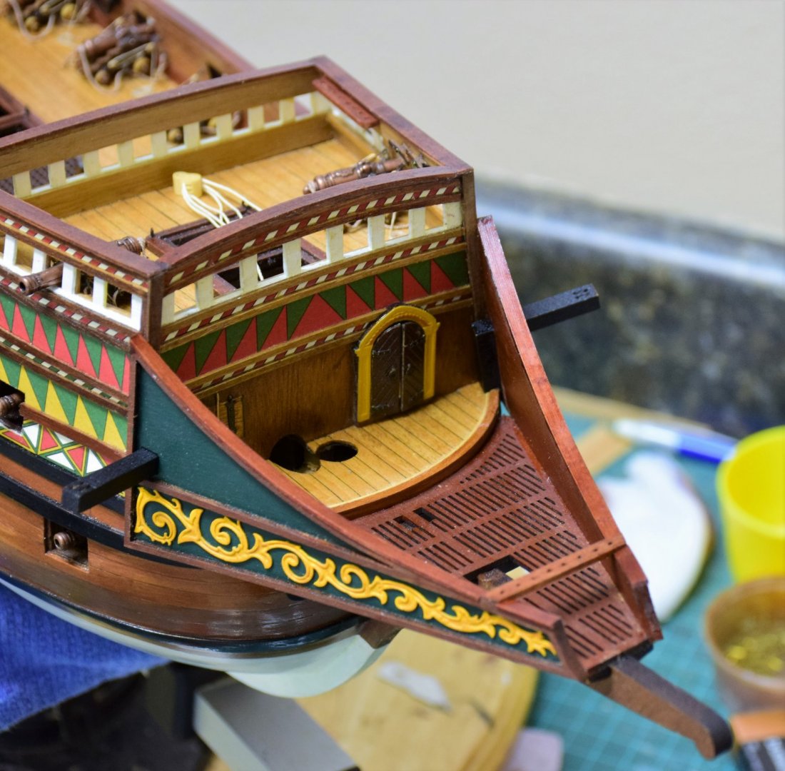
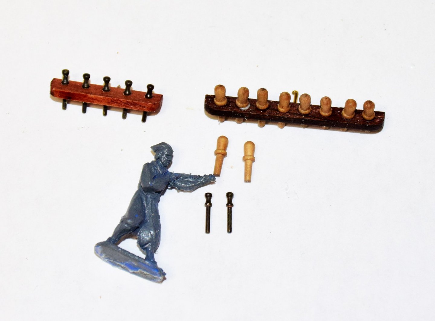
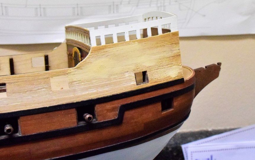
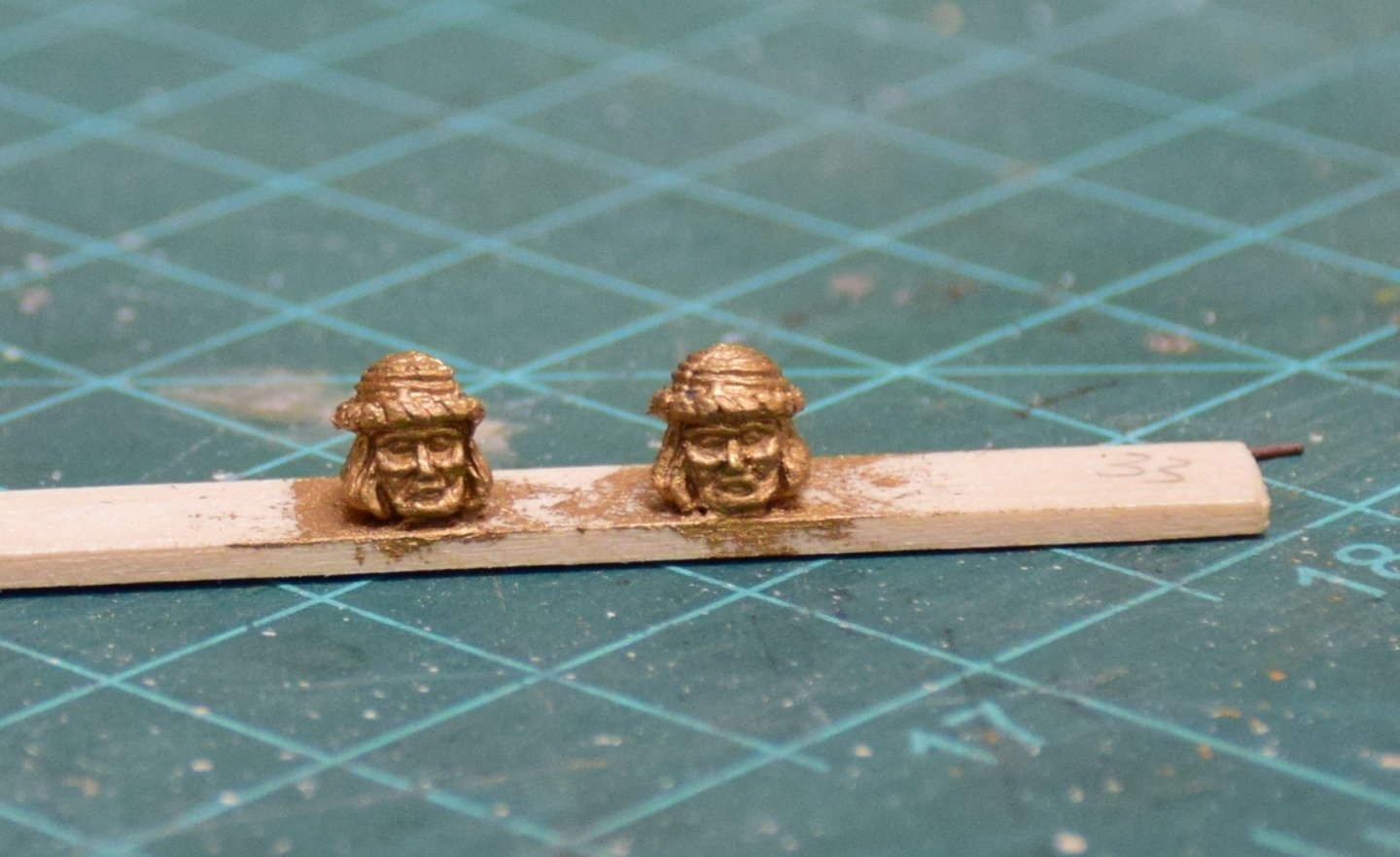
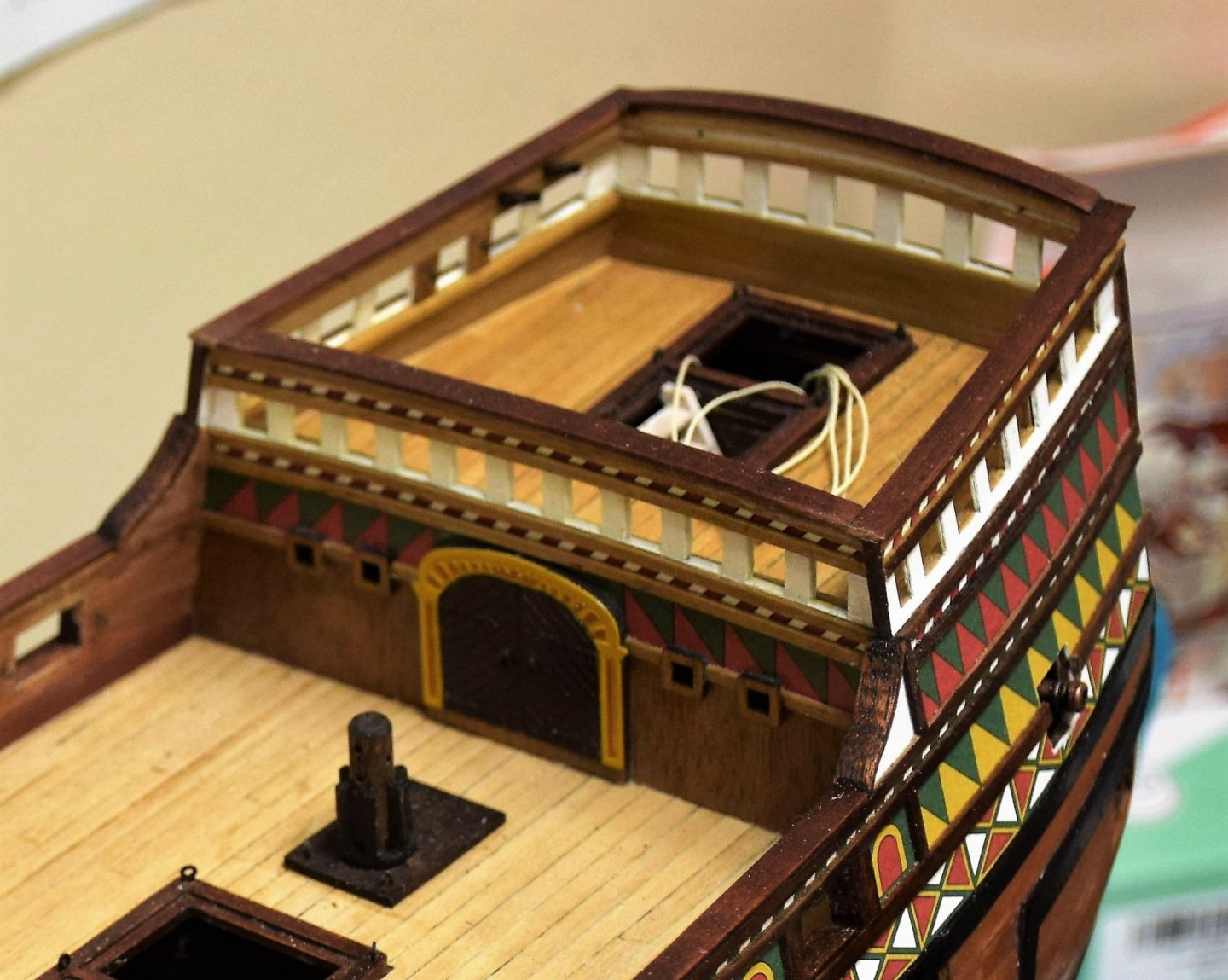
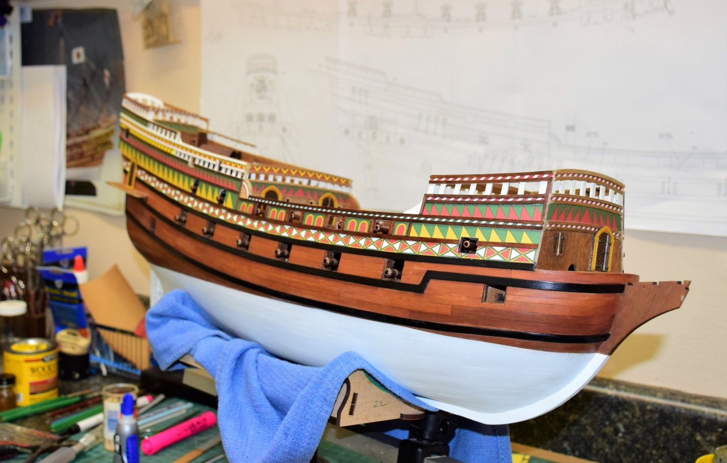
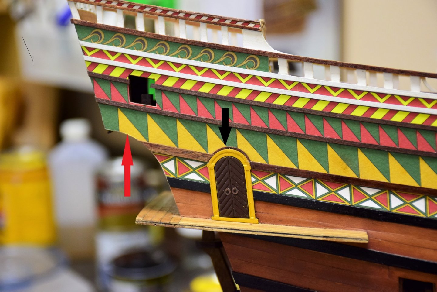
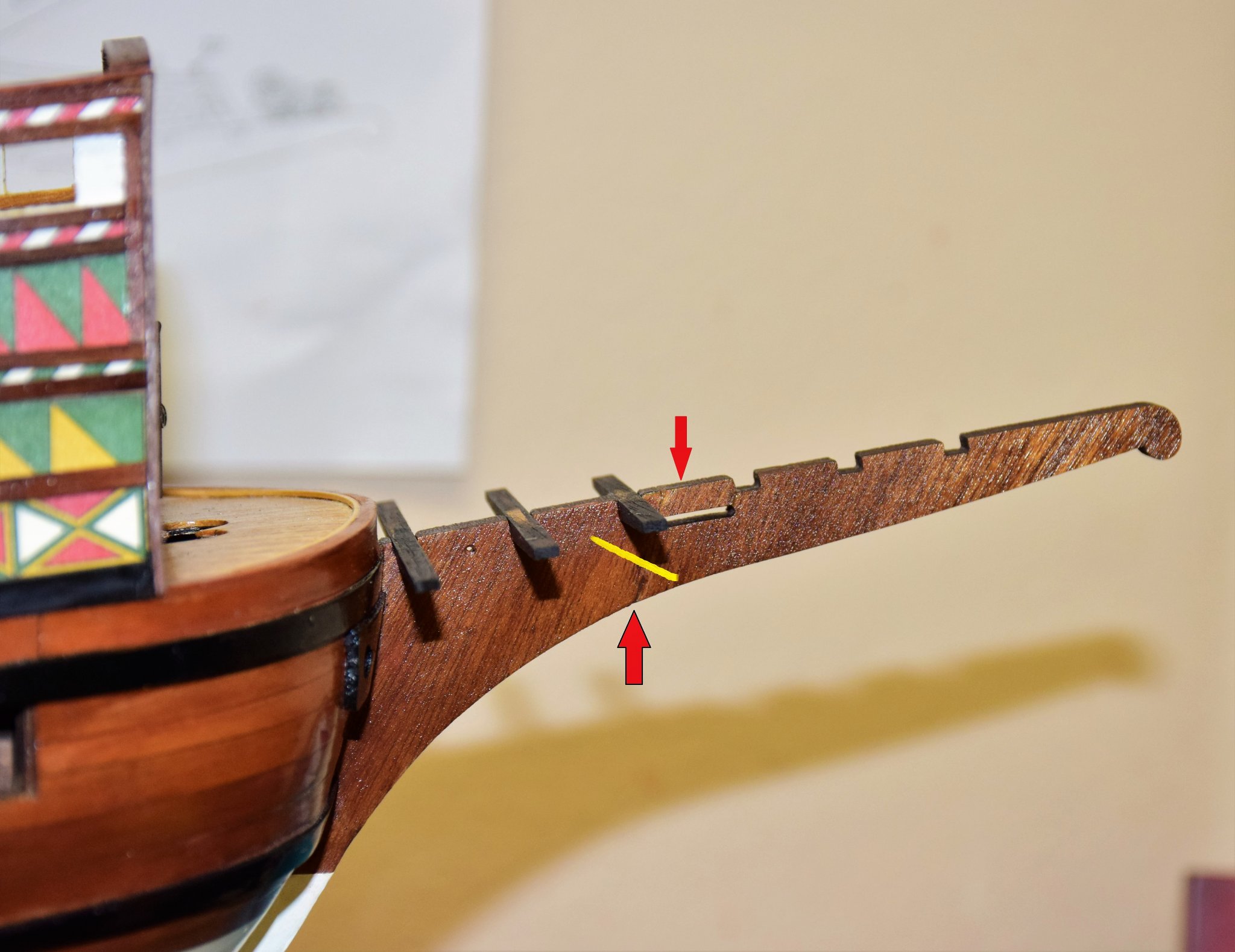
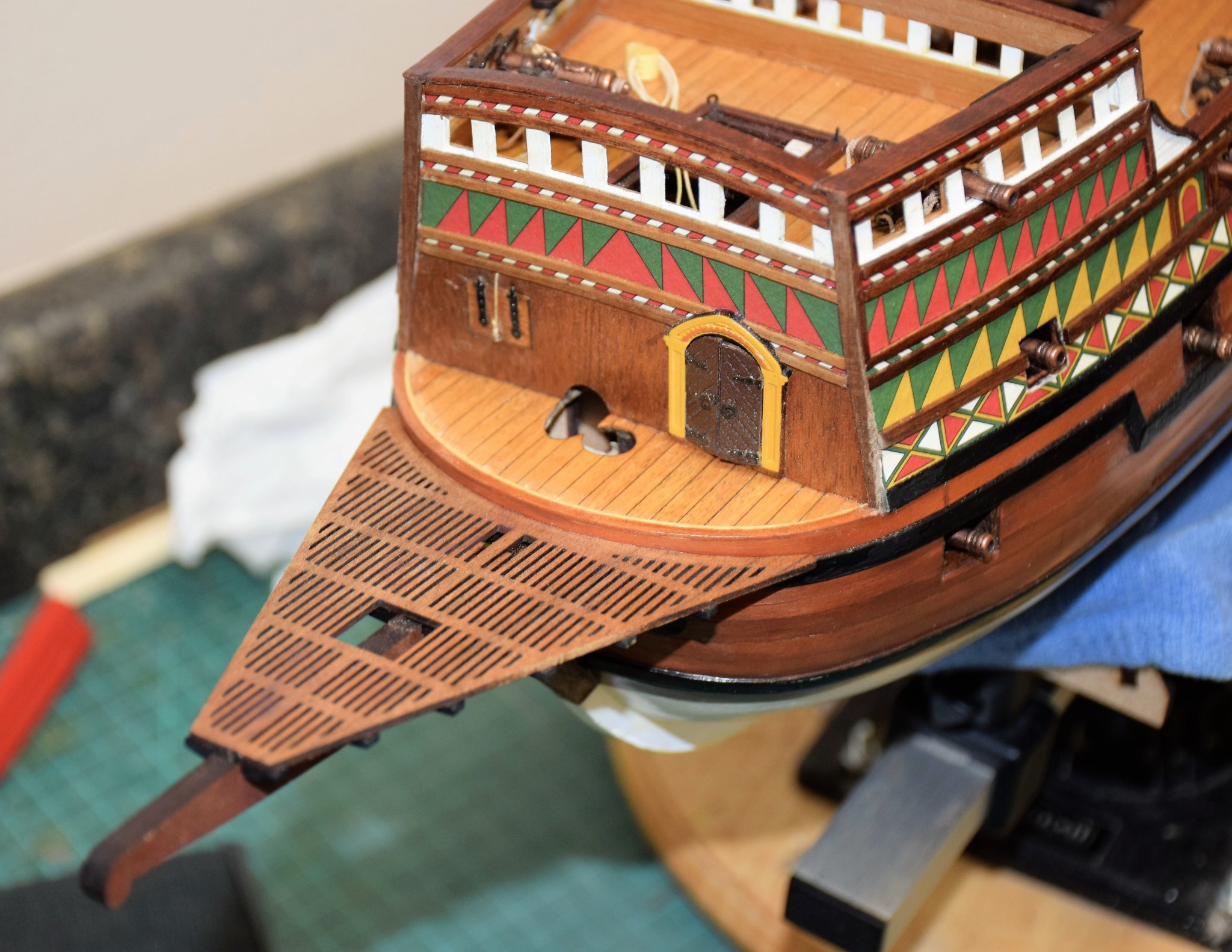
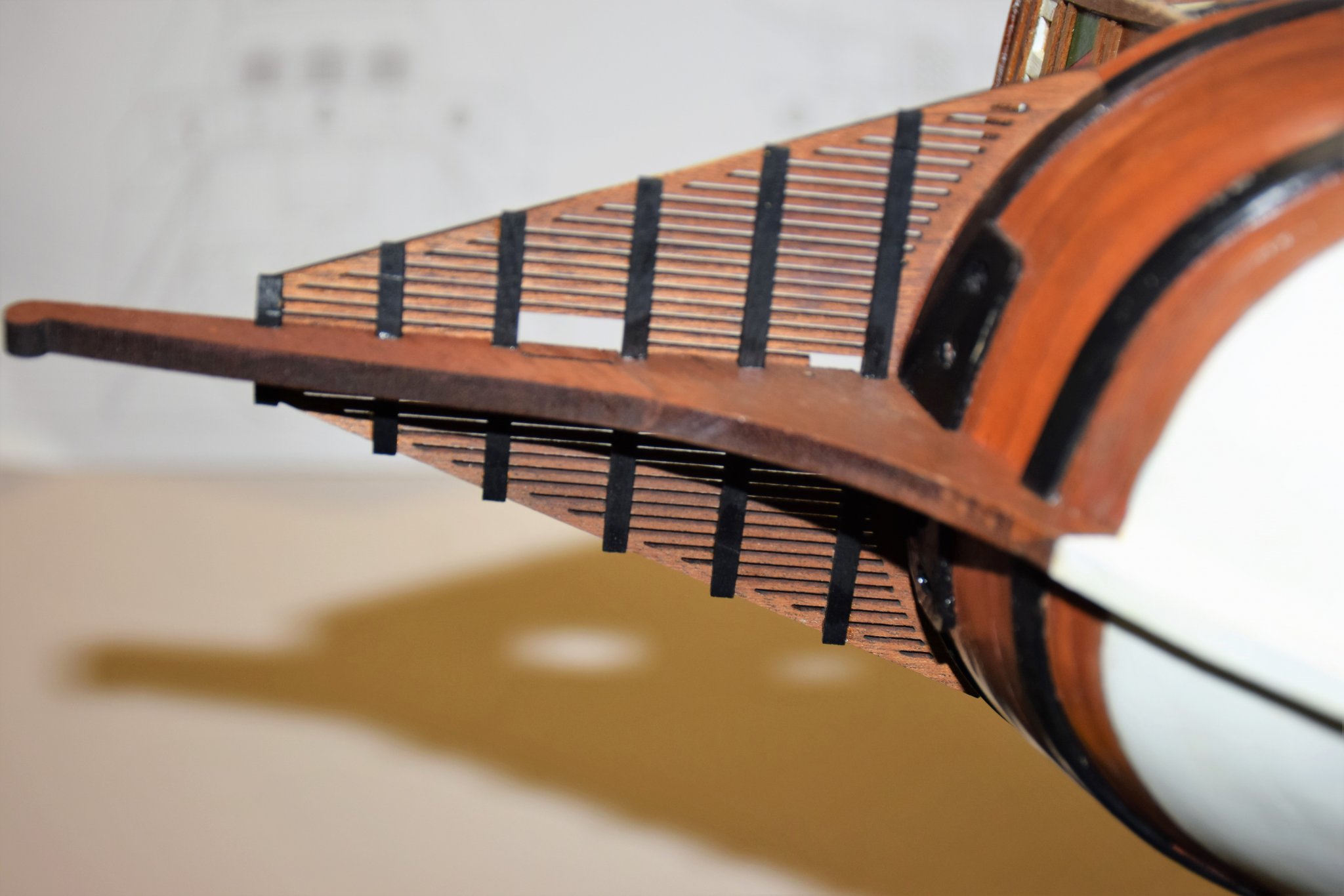
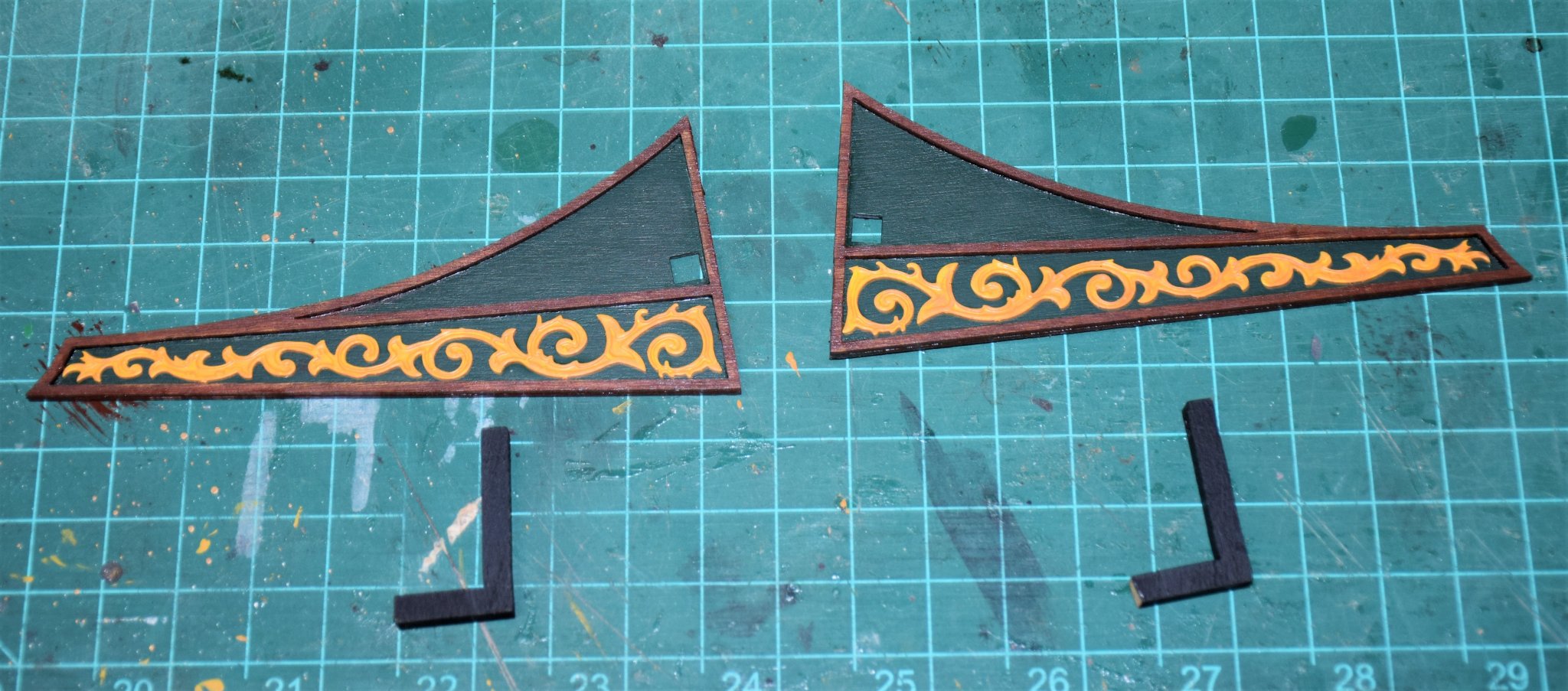
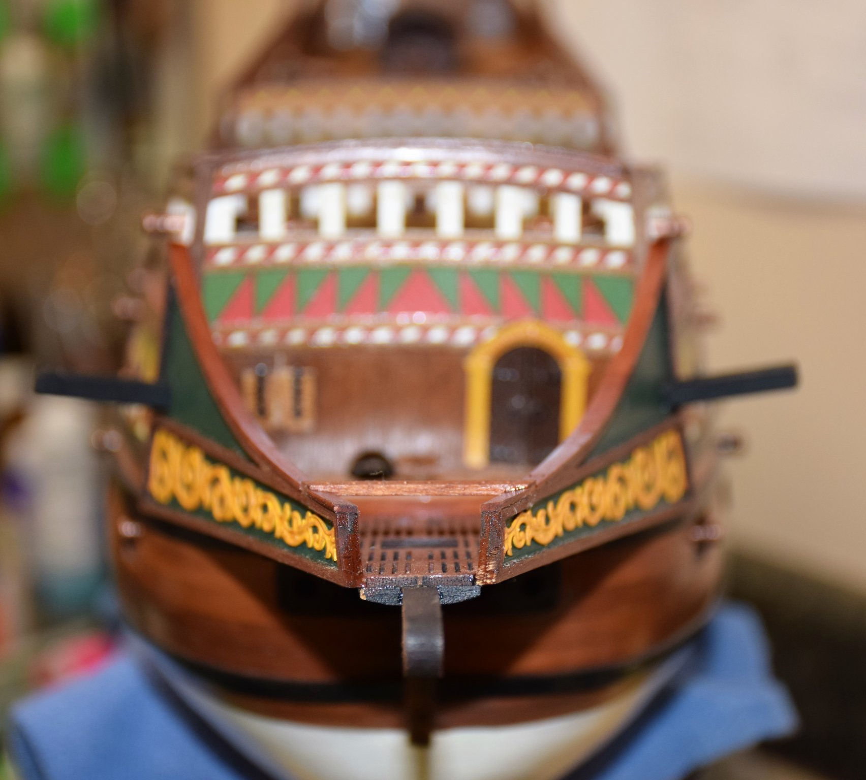
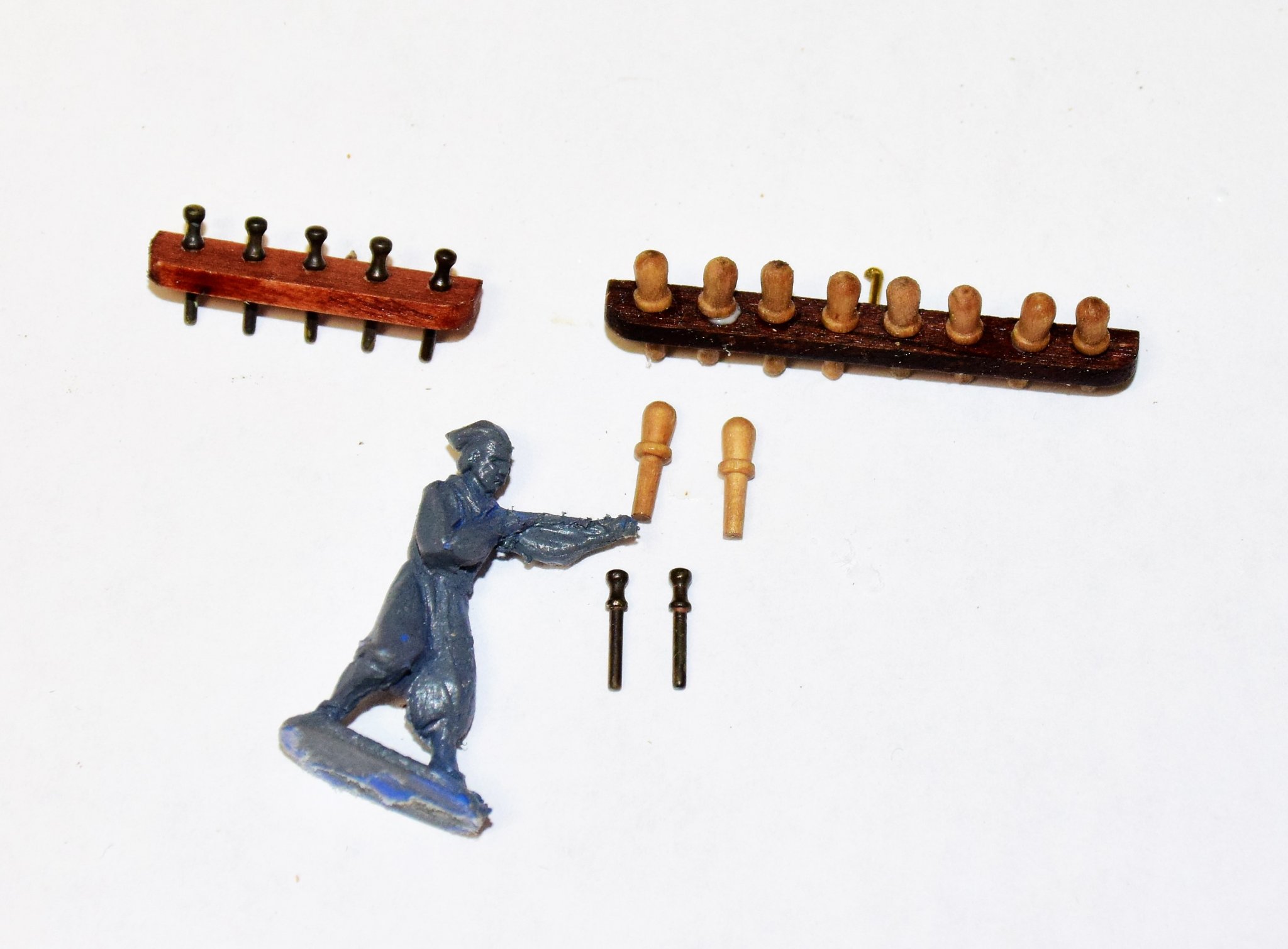
Greetings...on to the bow First order of business was to repair the stem. 2 pieces had to be glued back in place (red arrows in pic below). This would be a weak spot if not for the platform supports that sit in the slots on both sides of the break. Once the platform is in place there should be little chance of breakage from the bowsprit gammoning. Once all of the supports are in place the platform is glued to the supports. If the bow was planked / shaped properly, little to no sanding is required to achieve a good fit. Next, a small strip is used to line the edge of the forecastle bulkhead. Plans call for 1x2, I used a 1x3. This can be seen in the photo below. A small amount of this strip outboard was removed to accommodate the walls that will soon be placed The walls at the bow are painted green and lined with African walnut ("dibetou" in the kit). Have I mentioned how much i dislike this wood? It tends to fracture very easily along the grain. In removing the frames from the pallet, I ended up with 4-5 pieces - for each frame. The it was like a jigsaw puzzle to get them in the correct orientation to glue on the wall. See if you can spot the joints on the photo below. The photo etched brass decoration was painted and glued in place The L shaped wood below the walls are the catheads. four holes will need to be drilled into each cathead for the anchor tackle. I suggest this be done now off the model rather then after placement. Also, the catheads are almost impossible to place through the walls after the walls have been placed. Some trimming will need to be done to have them seated properly. They were placed through the hole in the wall and left ungluded. Once the walls are up they can be glued. End result... The top of the bow walls are lined with a strip of pear wood, 1x3 mm. forward belaying pin rack was also placed. This got me thinking about the belaying pins supplied in the kit and just how many belaying pins are found on a ship of this period. As the kit was designed by Chris Watton, I figured that was good enough for me. Problem with the pins as supplied is that they are quite out of scale. The figure below is 1:72 which i figure is close enough for a 1:64 model. Note the size of the pin - almost as big as his head! 8 mm brass pins were ordered from Model Expo, blackened and placed in a new rack with smaller holes. IMO, the brass seems to be much closer in scale than the wood. Of course, this meant removing all the pin racks previously place and making new ones from spare wood. Here is a shot amidship that shows the new pins and racks in place (along with the swivel guns) Next up, gunport and channel placement and stern gallery supports. Also starting to think about how I am going to do the "water" that the ship will eventually sit in. I'd like to get this done before i start with the mast work and rigging as it will be easier to move the model about with the lower profile w/o masts. jeff


-
Thanks for the kind comments. re: next build log, i have no idea at this time what is up next as I still have a fair amount to do with this ship. I usually don't start thinking about the next project until my current one is almost done. And who knows what may be available at that time - so many interesting projects from Syren, Vanguard and CAF. Who knows, maybe the 1:64 Victory from Amati will be released by then! Jeff
-
Greetings! After a rather long interlude (trip to New Zealand, work, general malaise / inertia), I am back at work in the shipyard. All of the cannons have now been rigged, some with leftover blocks from Warner Woods (these were quite good) and the rest with blocks from Syren (equally as good). Kit blocks are in the trash. Pin rails and Staghorn cleats have also been placed (some visible in the photos below) Now onto the stern. There are 5 parts to the walls that make up the stern balcony. After painting, the forward wall (also the smallest) was placed first. this required a bit of sanding to get the profile correct against the hull. Next were the 2 sides followed by the stern. a mm or 2 was removed from the side panels to get them flush for the aft wall. Overall not too difficult but it was important to let each piece dry before moving on as there is not a lot of surface contact for the glue. Below are 2 views... Next, paneling, made of 2x1 mm strips, is added to divide each wall and the capping rail is placed. I recommend gluing the walls first then adding the 2x1 mm strips rather than adding these strips to the walls off the model. And finally, photo etched "emblems" are placed on the walls, painted whatever shade of yellow suits your fancy. next up, work on the bow, including repair (way earlier in this build the stem had a close encounter with the wall and snapped off). Jeff


-
Hi Jonathan. Re: the whipstaff. It has to be able to move freely up and down so you can eventually seat the tiller (at a much later stage) into the opening at the bottom of the whipstaff. You don't want to be caught with a glued staff and have a hard time placing the tiller when the assembly is covered with another deck. A piece of tape will suffice to keep the staff from falling out of the assembly. Jeff (Revenge log under xodar461)
.thumb.JPG.9ddeb4dd99b5836c0ad2937890074e09.JPG)
-
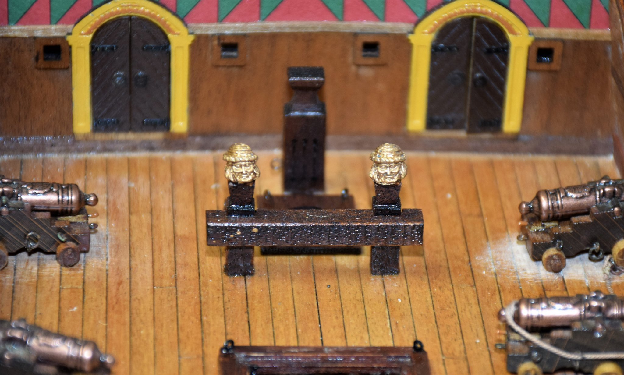
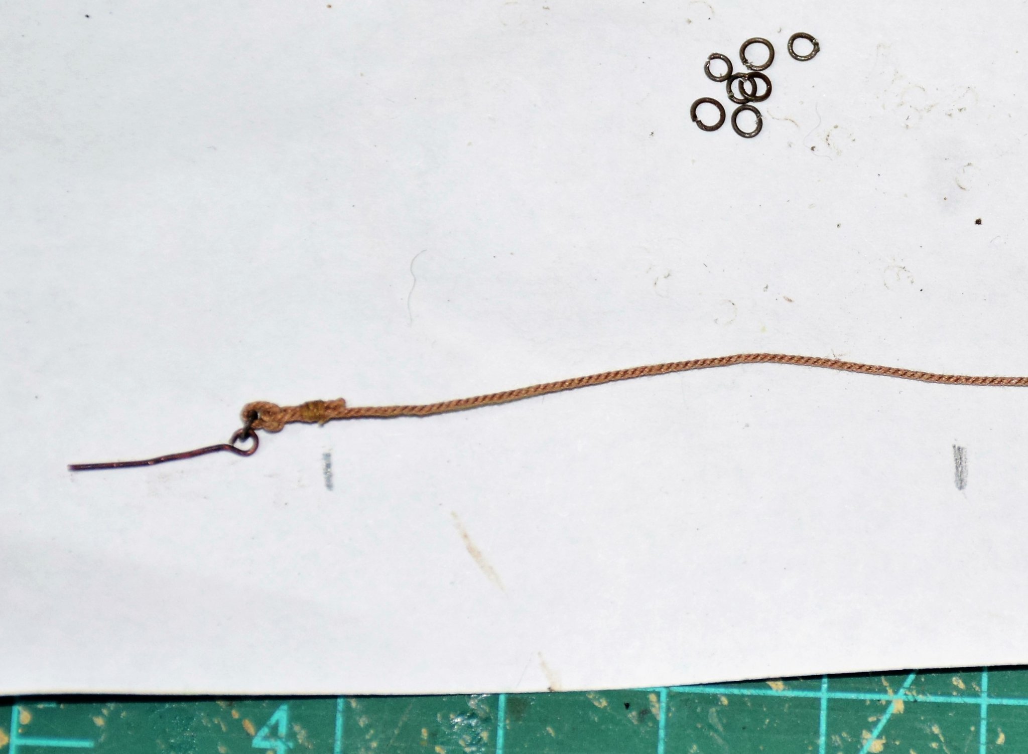
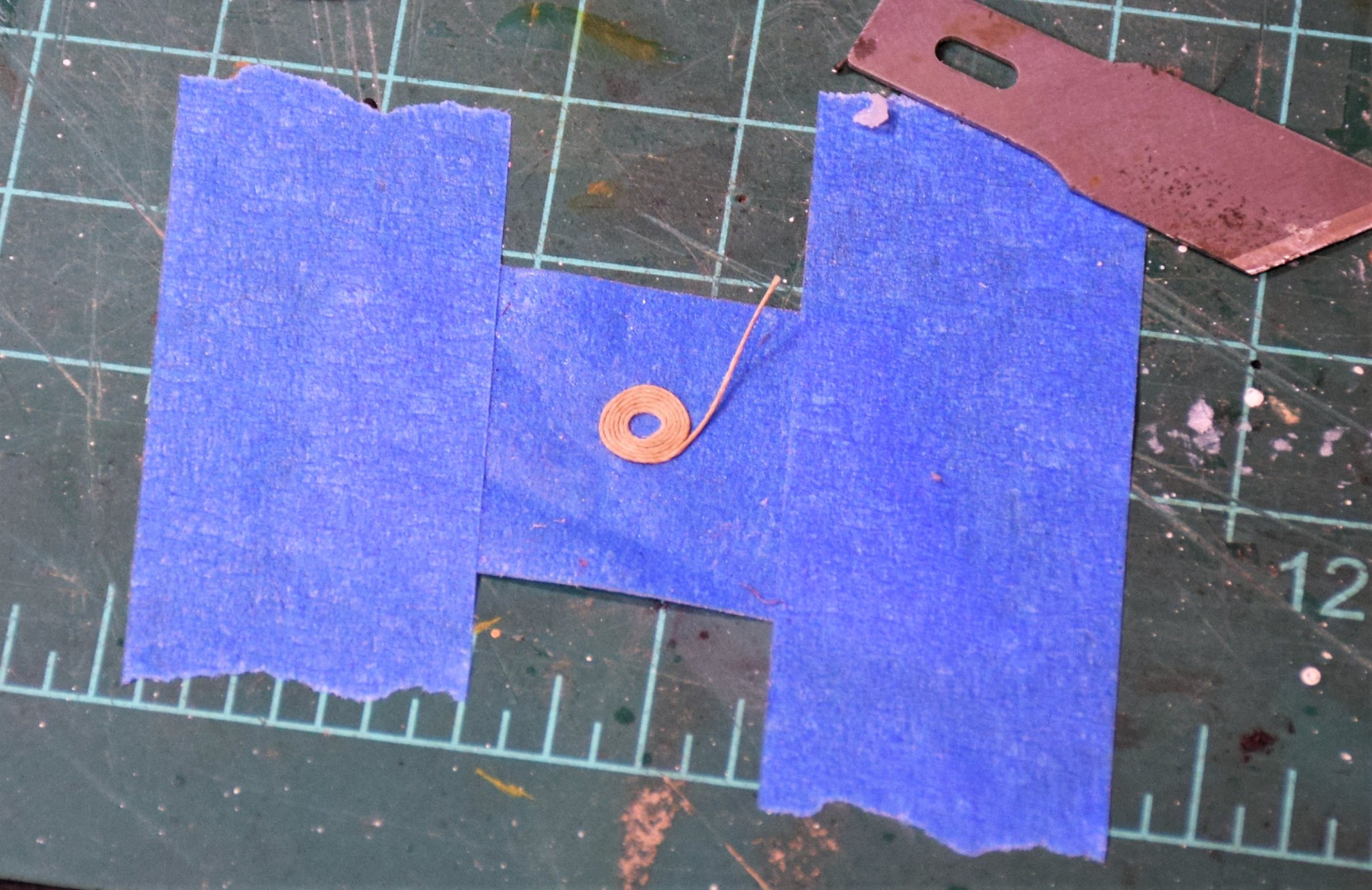
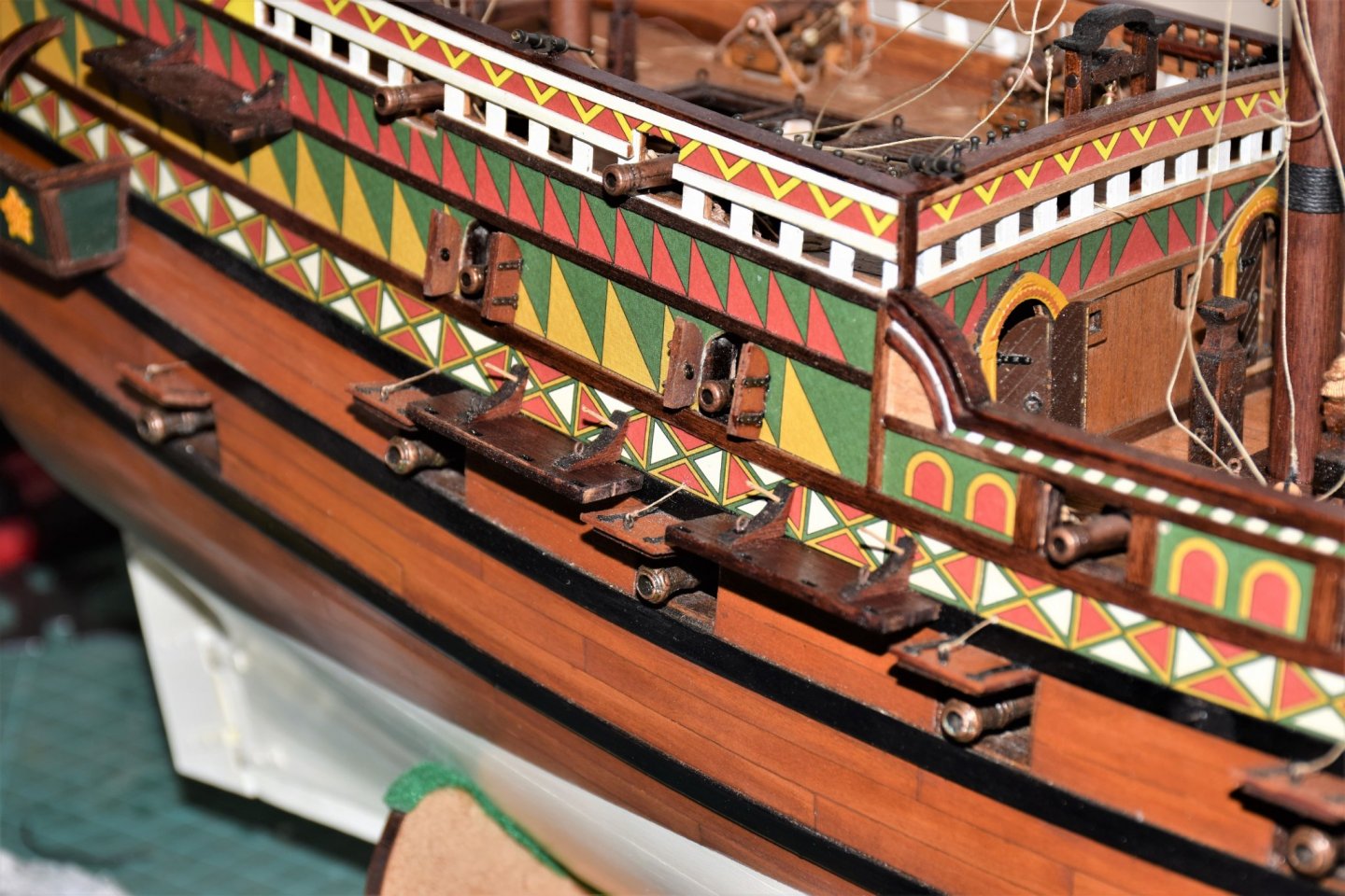
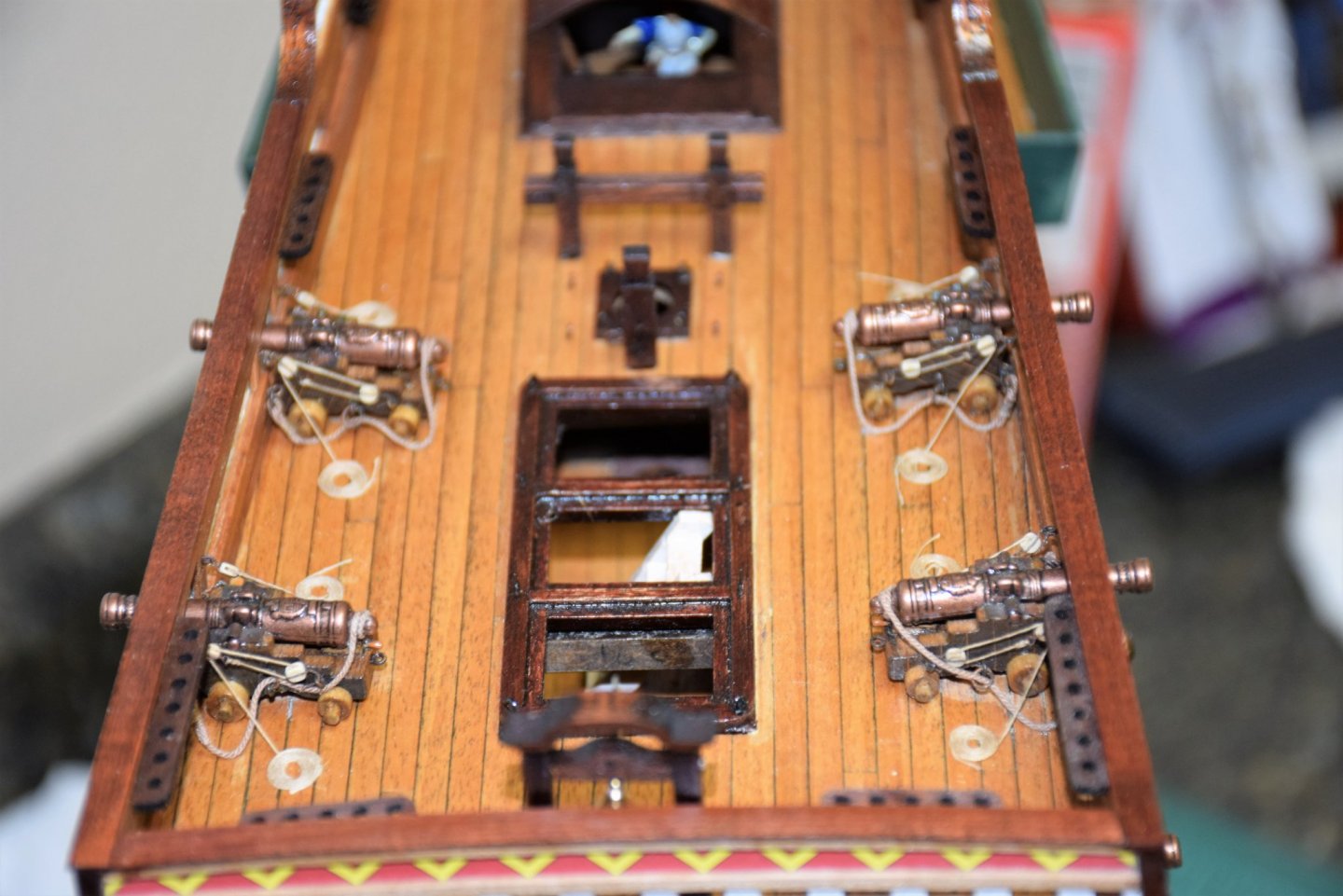
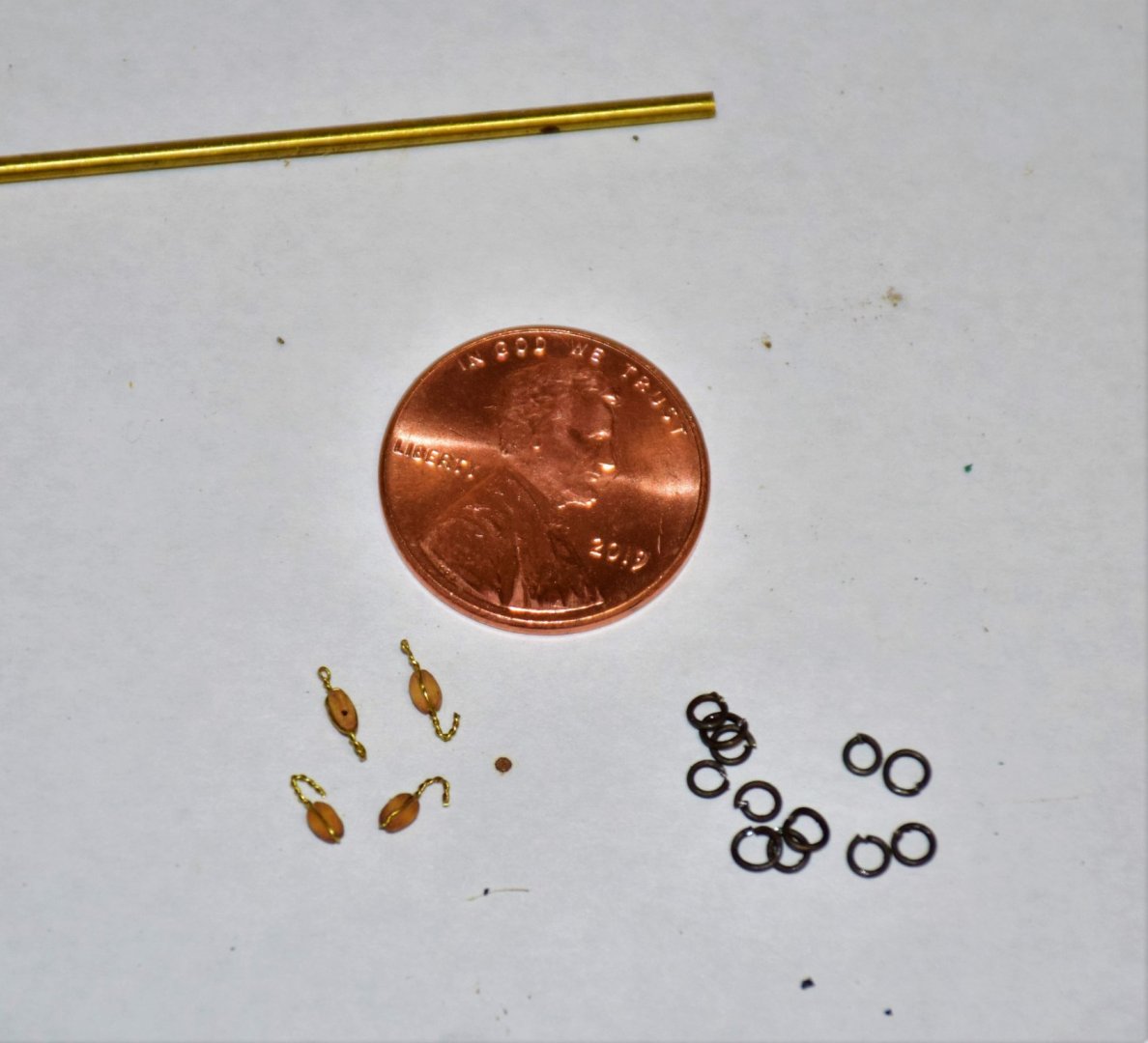
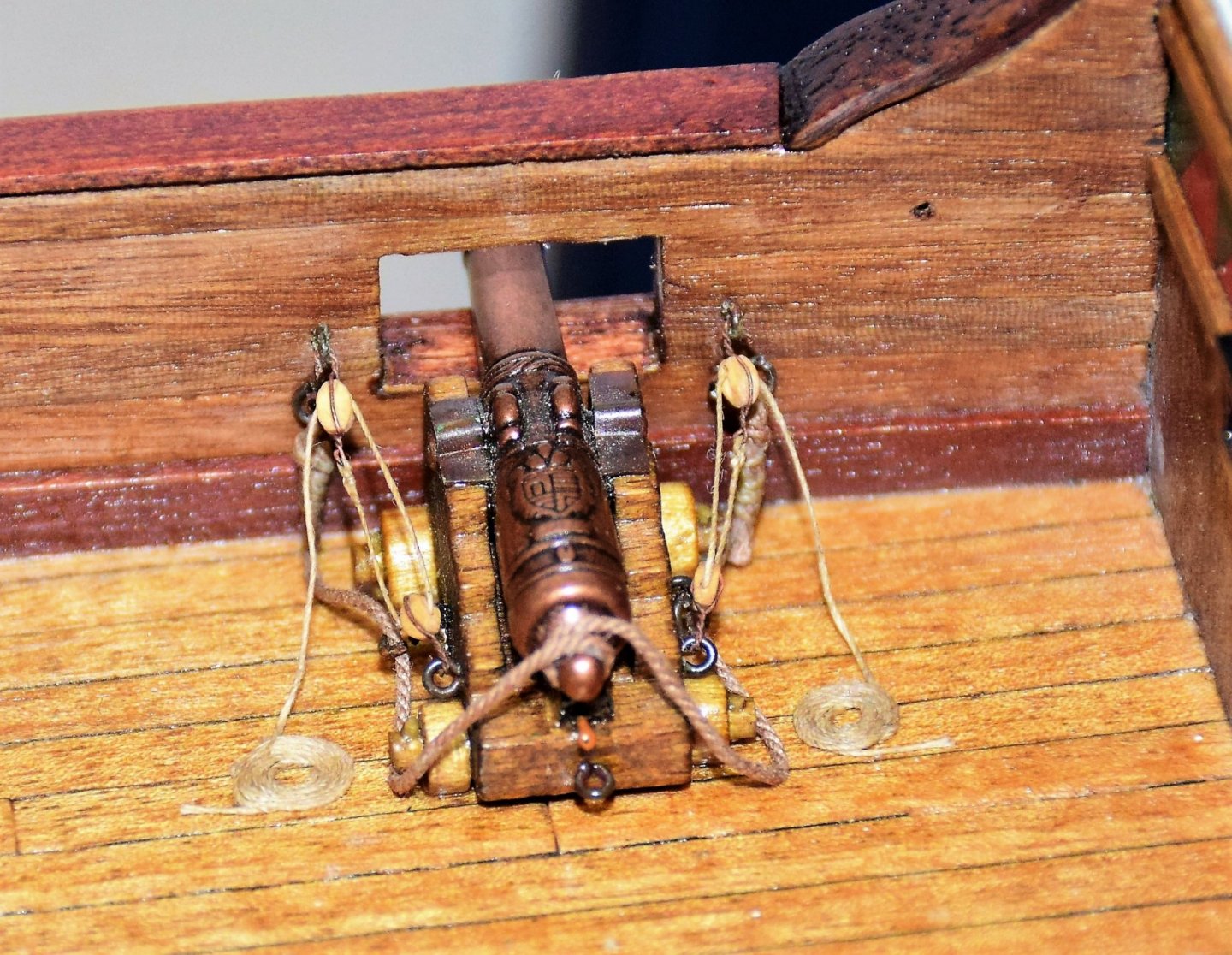
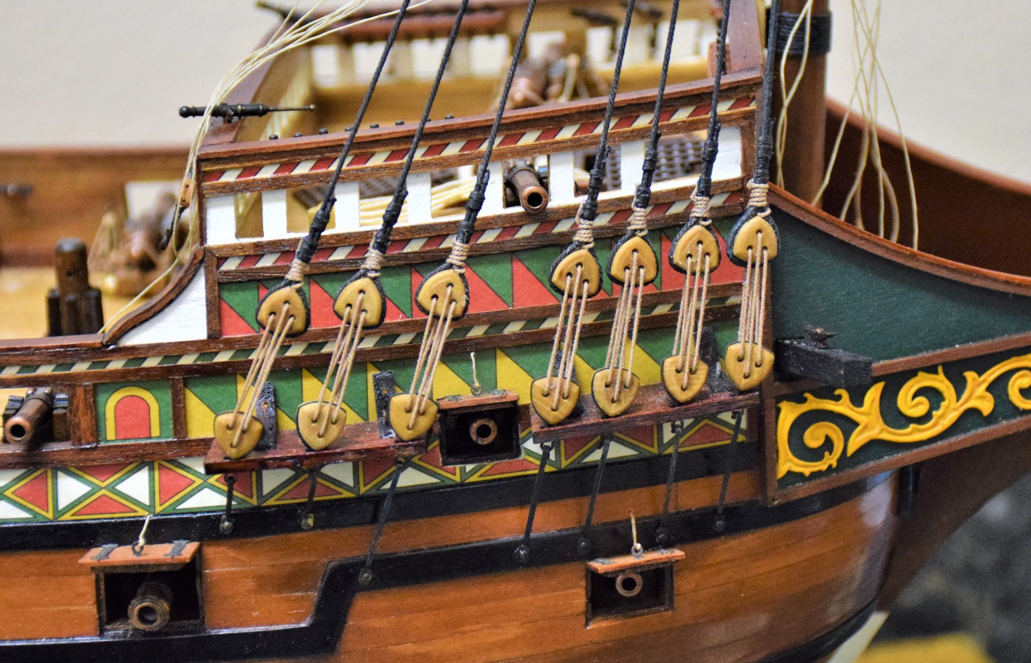
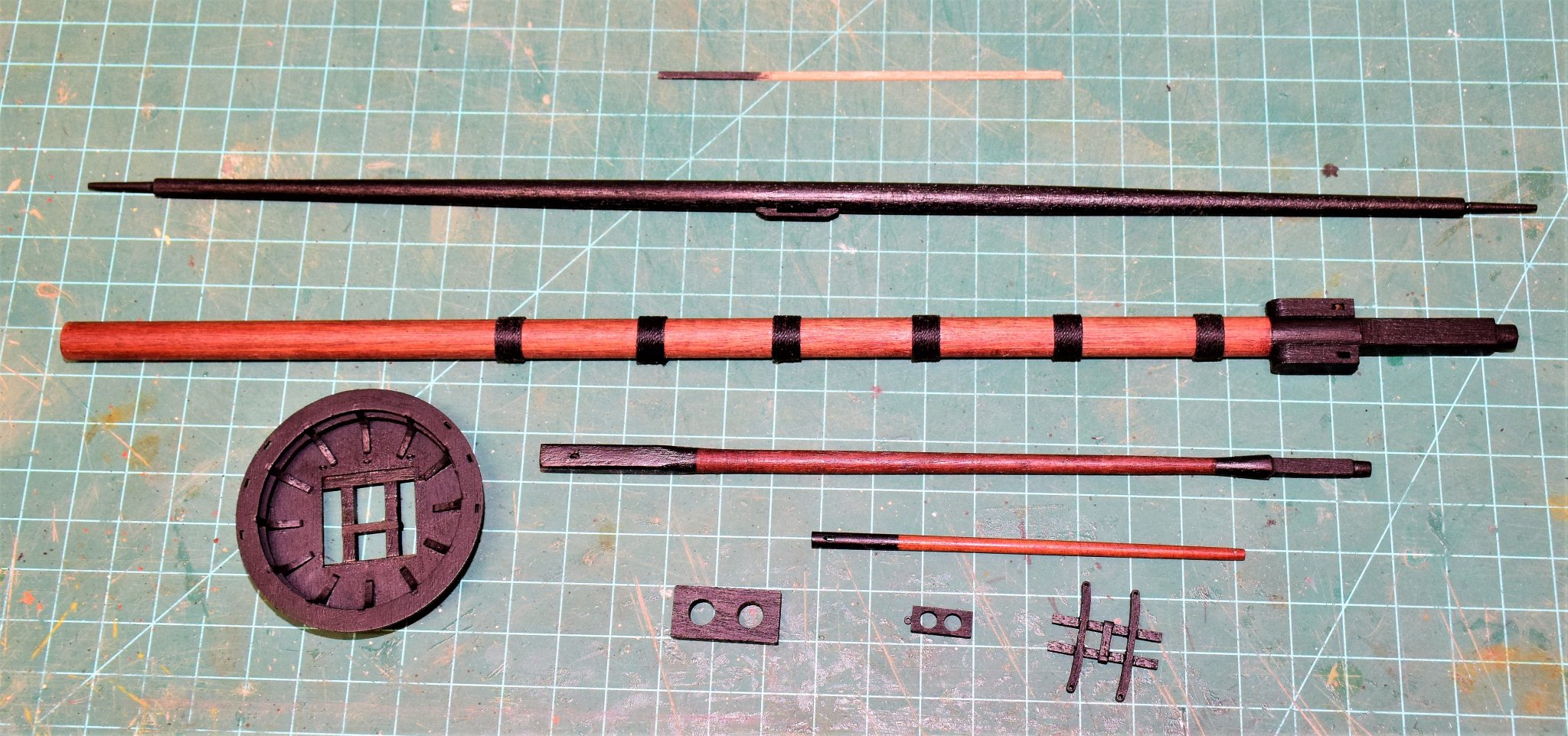
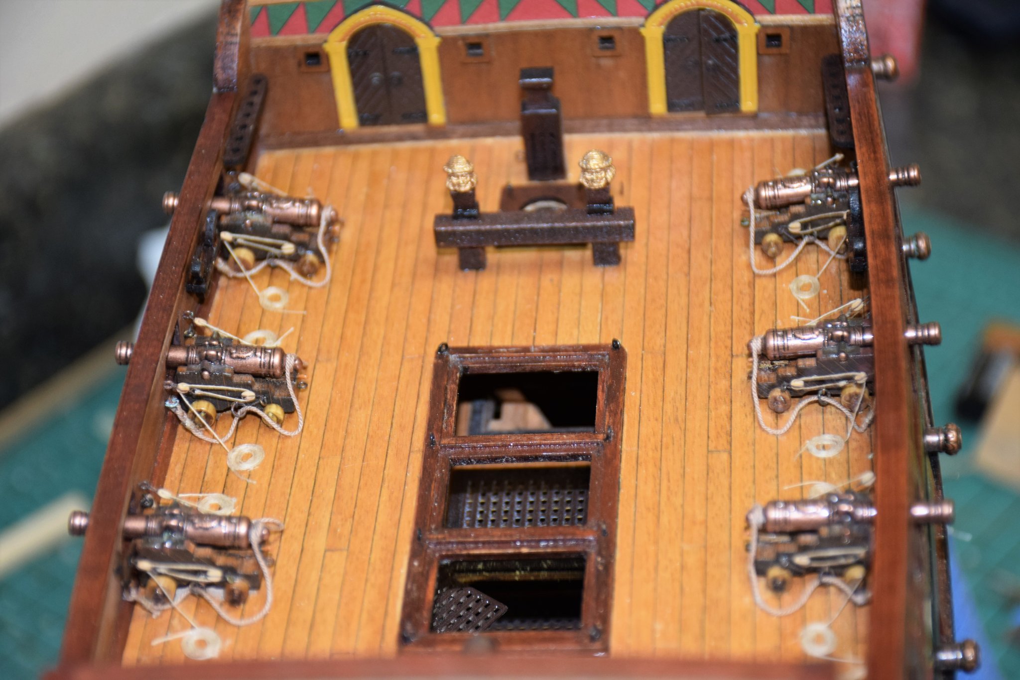
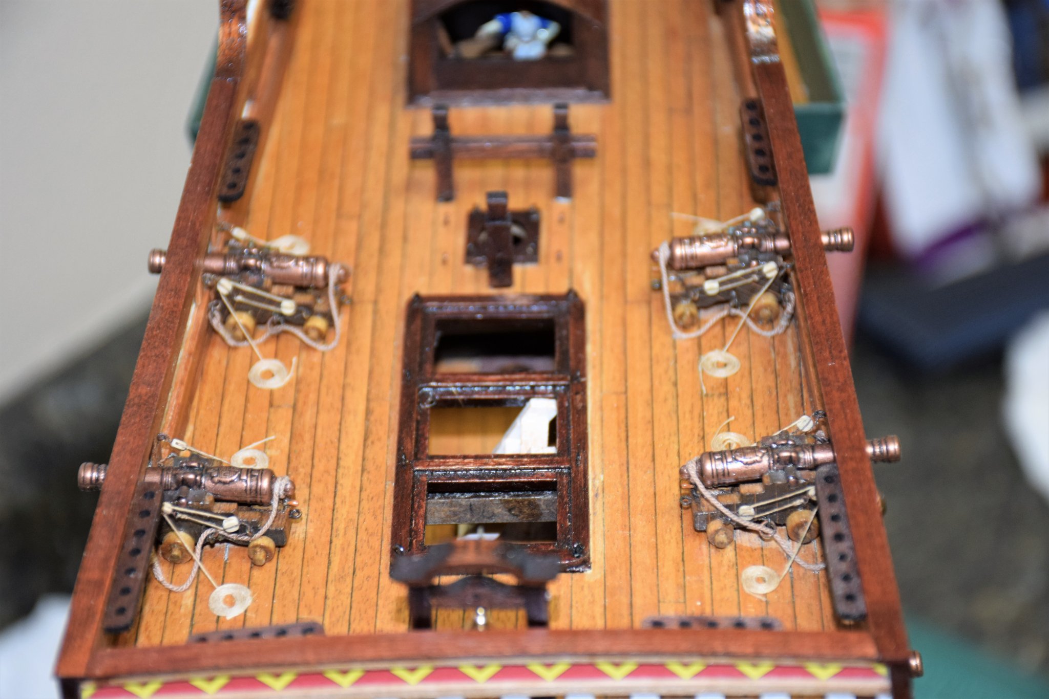
Greetings Placement of the main mast bitt finished up with most of the deck fittings except the grates. 2 castings go on top of the supports, painted gold rather the brown as the manual suggests Next up in cannon rigging. I used light brown rope of 0.63 mm (Syren) for the breeching rope (0.5 mm would be the correct size at a scale of 1:64 but I thought anything smaller looked too small). The rope in passed though a ring (which is attached to a eyebolt) then seized (using 0.1 mm rope) after a half hitch is placed. The cannons are then glued to the deck and the eyebolt is glued into the bulwark. The gun tackles are next. Blocks are 2.5 mm (left overs from Warner Woods), tackle 0.2 mm rope. Each block would be stropped with a hook but rather that make such a small hook, the bock were stropped with 32 gauge wire which was then blackened. Blocks supplied with the kit will be discarded at they are the typical non realistic square kit blocks. One down, 13 to go Train tackle at the rear of the gun has not been placed as I will be a bit short with the 2.5 mm blocks. I'll get more from syren when I have more stuff to order.. for anyone interested in how the rope coils were made... 6 or 7 turns, then a light coating of glue before lifting off the tape. Jeff


-
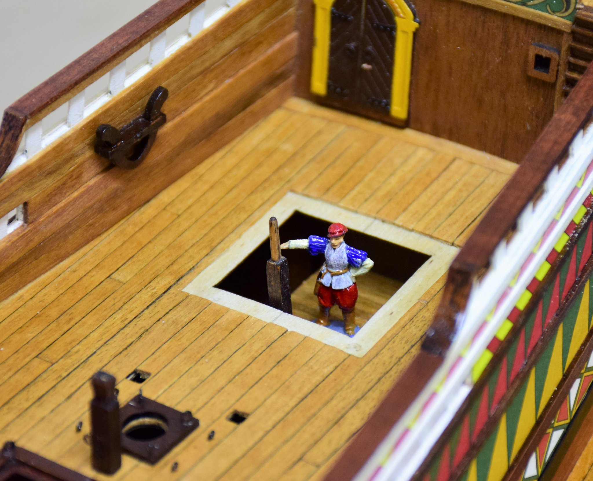
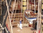
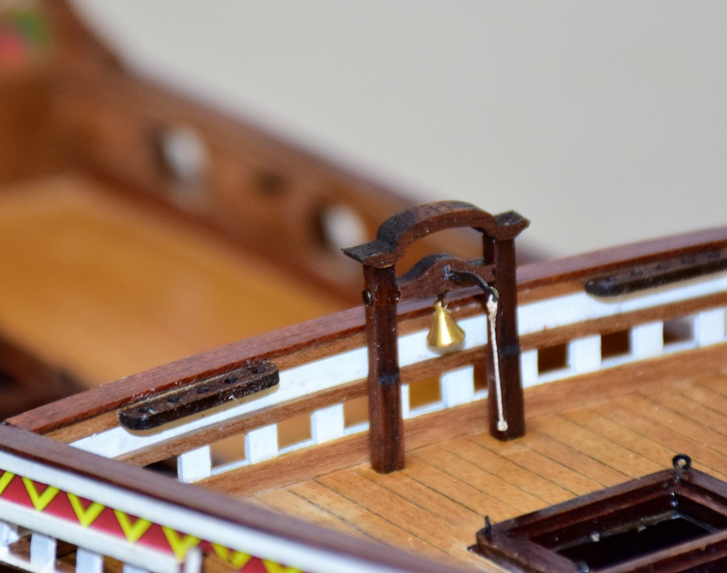
Greetings After to rails I decided to place the hawse hole boards. These are 3 mm MDF and will have to be made to curve from side to side and then a little from top to bottom so it sits flush on the hull. Both parts were soaked in water (did not see much swelling in the MDF) and then clamped around an appropriate sized pot. Once I had the side to side curve six hole were drilled so the piece could be nailed to the hull. The holes were slightly smaller than the nail. The board was then glued and nailed to the hull, using a counter punch to drive the nails a bit below the surface of the MDF. By nailing the board I did not have to worry about how to clamp this piece in place if it was just glued and the board was now flush with the hull in both planes. on the pic below, the starboard hawse board has been nailed; on the port, the nails have been covered with wood filler and sanded. the second pic shows just the port board Photo below shows final result. The hawse holes can now be drilled into the hull to accommodate the anchor cable and painted black Back to some deck fitting - belfry has been constructed and placed and finally - as I plan to display the model at anchor in the bay of cadiz, I will need some crew. Though not much is available in 1:64 (and I am not good at carving), I did find some period figures in 1:72 which I feel will be close enough (5"7" at 1:64 is a 26.5 mm figure and the ones I found are ~25.5 mm). First crew member is manning the whipstaff. Next, a few more deck fitting and then the cannons will be placed. Jeff


-
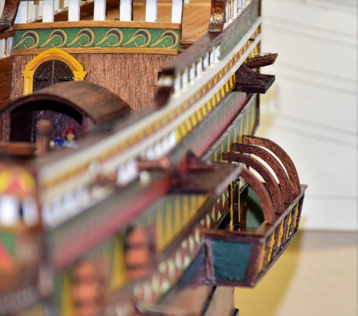
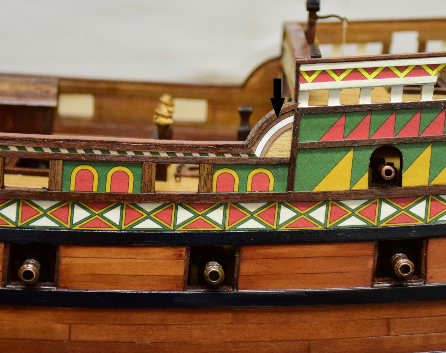
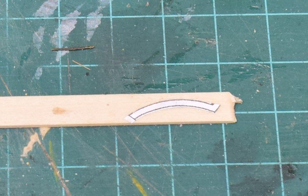
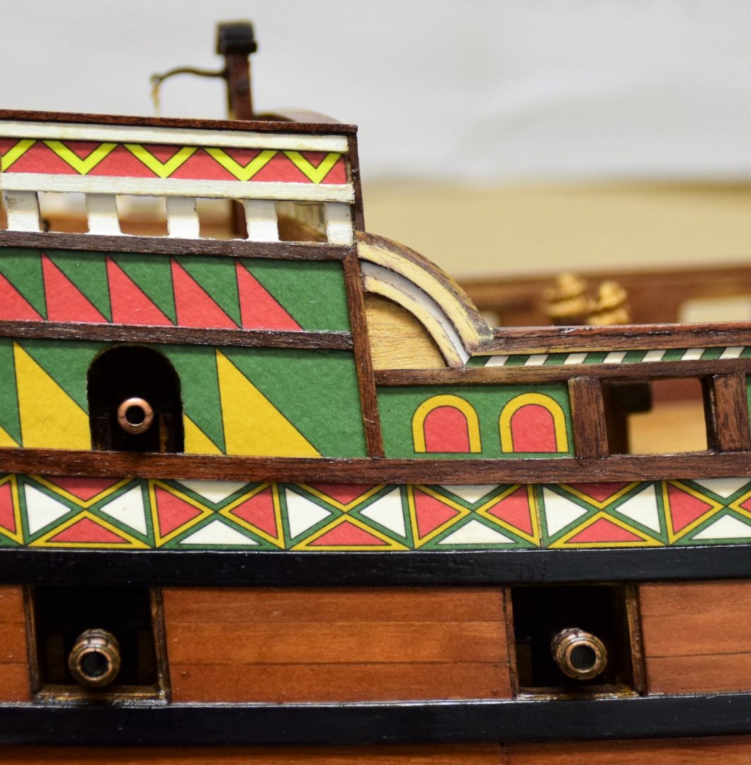
Greetings Next item to be completed are the capping rails. not a difficult chore but several of the rails running across the ship need to be curved and sanded to be sure they smoothly join the rails running the length of the ship. When all the rails were place, one area amidships needed attention Arrow on the pic below shows an area where 2 curved wood pieces go to complement the small wales These have quite a curve so they were made by hand. a photocopy of the area was glued to a 2 mm strip of bass wood and then trimmed to size. one glued in place below now both... finally stained. Some of the surrounding wood has to have some stain reapplied as it was removed with the sanding. next, some work on the deck fixtures Jeff


-
"Breeching ropes were three times the bore length of the cannon, and ranged from 4 to 6 inches diameter, depending upon the size of the gun." In the table above, the size of the breechings is given in inches. This is not the diameter of the rope but rather the circumference. When a reference book gives the size of a rope or cable, the measurement is typically the circumference. For model kit rope and those that can be bought independently (IE Siren), the measurement given is the diameter. Therefore you have to calculate the scale size rope needed using D=C/π and maybe convert from imperial to metric measurements. A 2.6 mm breeching rope would be way out of scale at 1:48. A 5 in breeching rope at 1:48 would correspond to a 0.8 mm diamter rope. Jeff
-
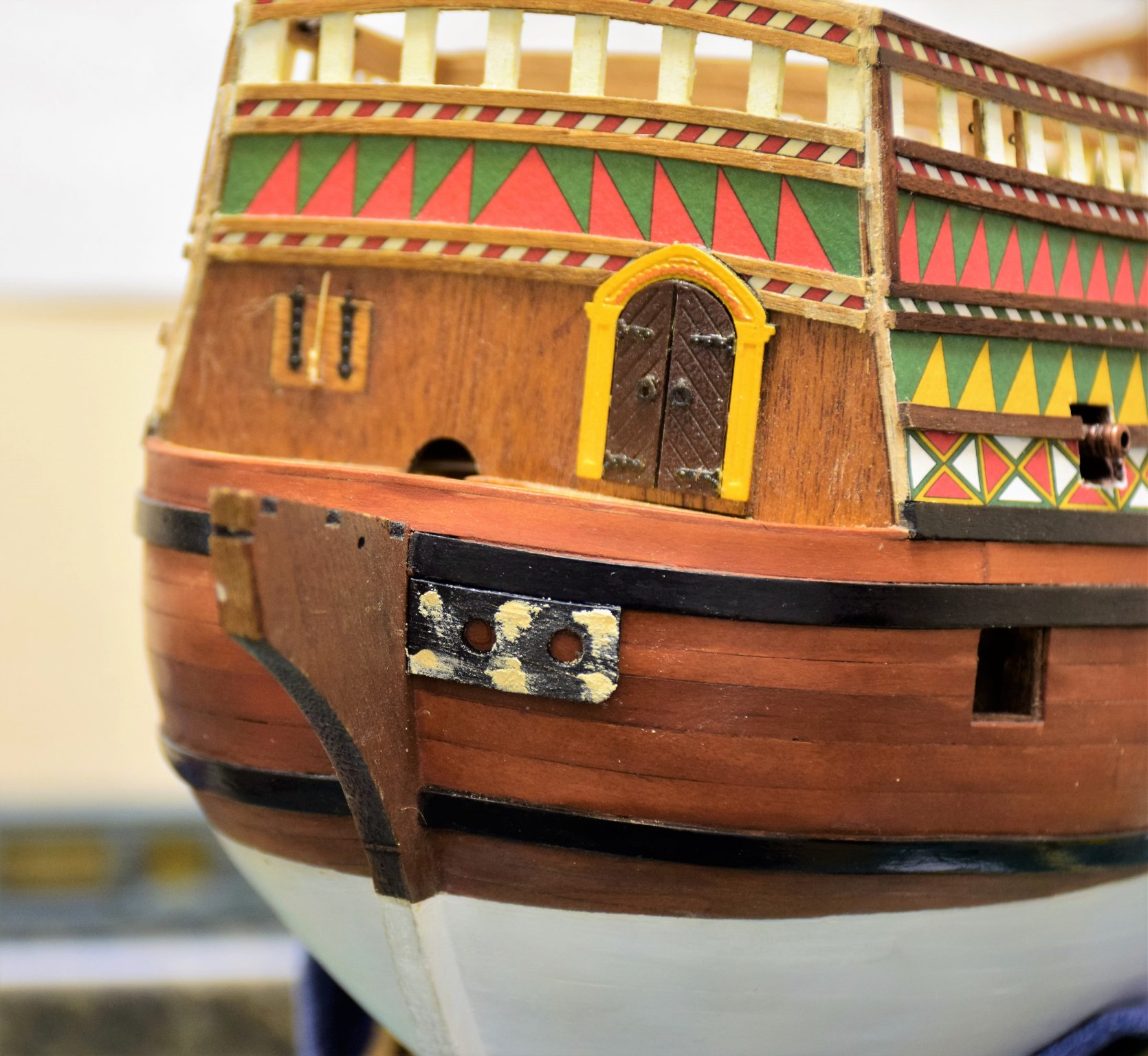
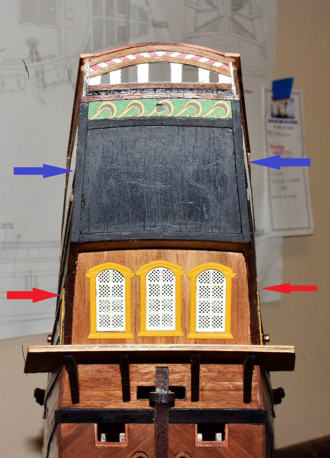
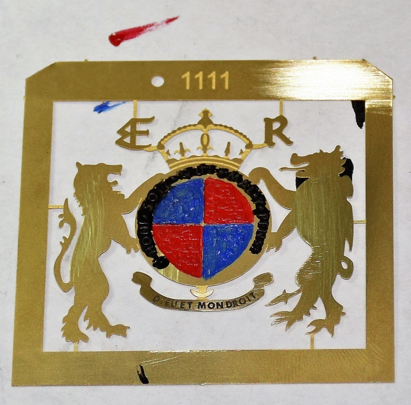
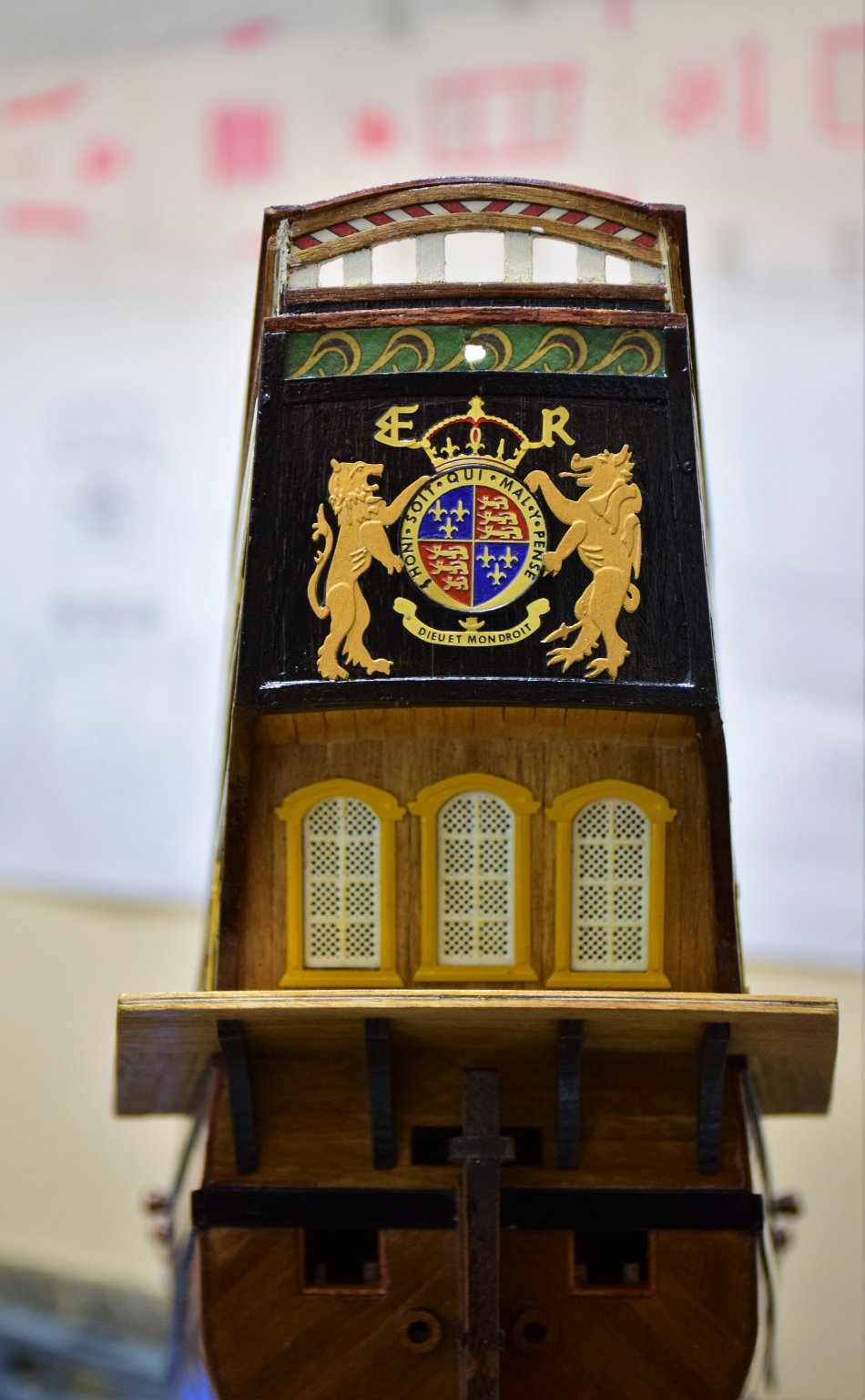
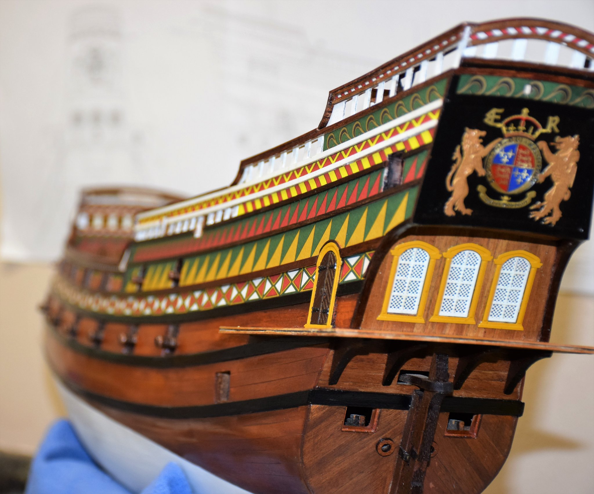
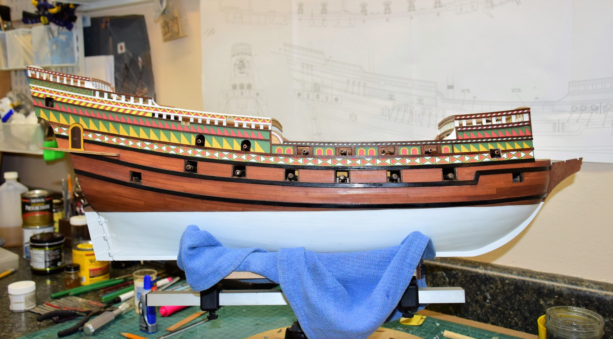
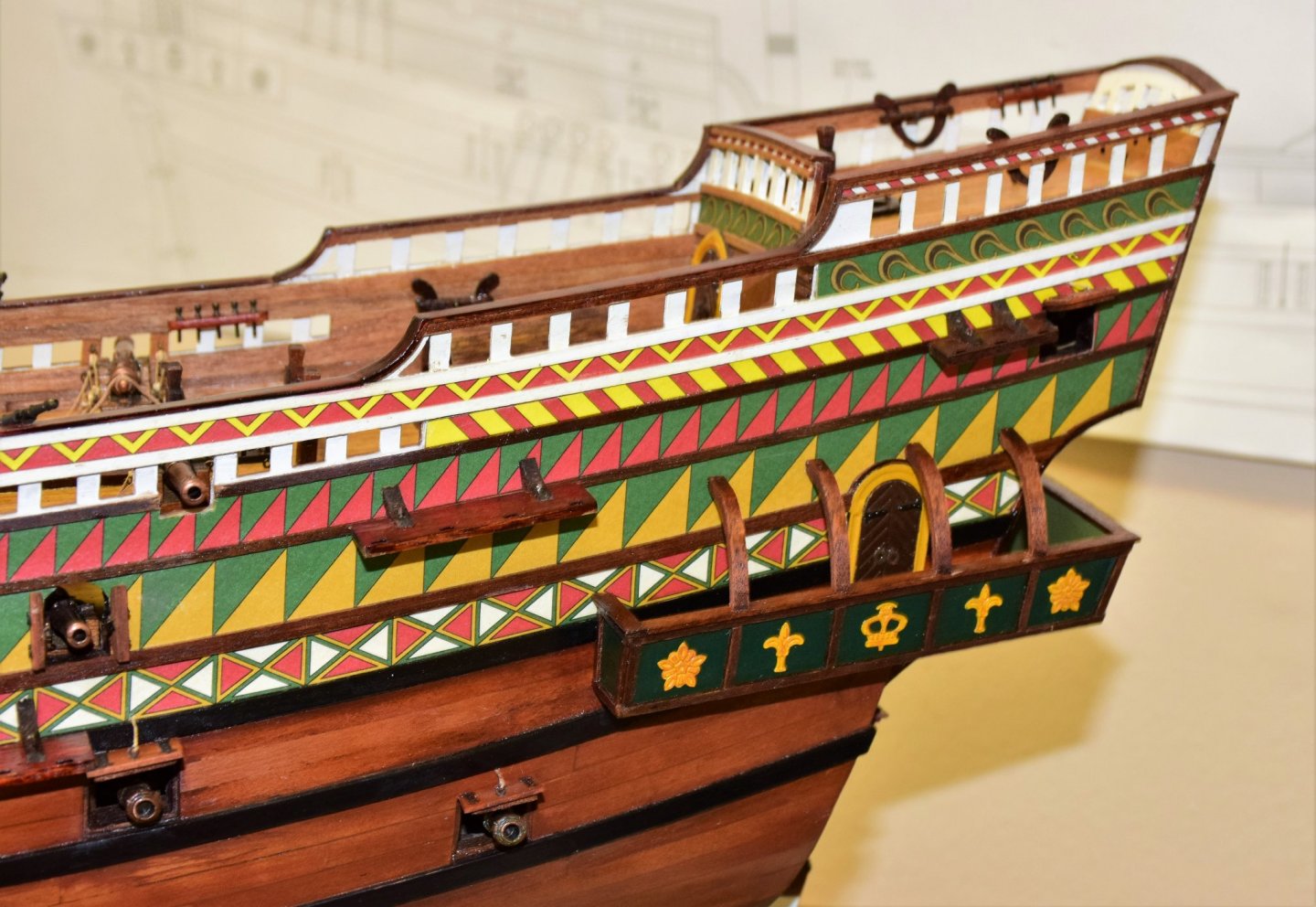
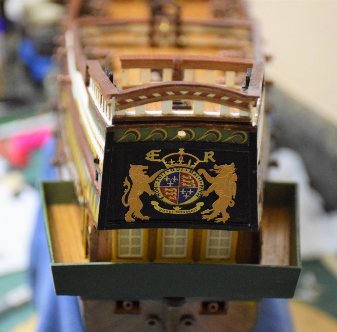
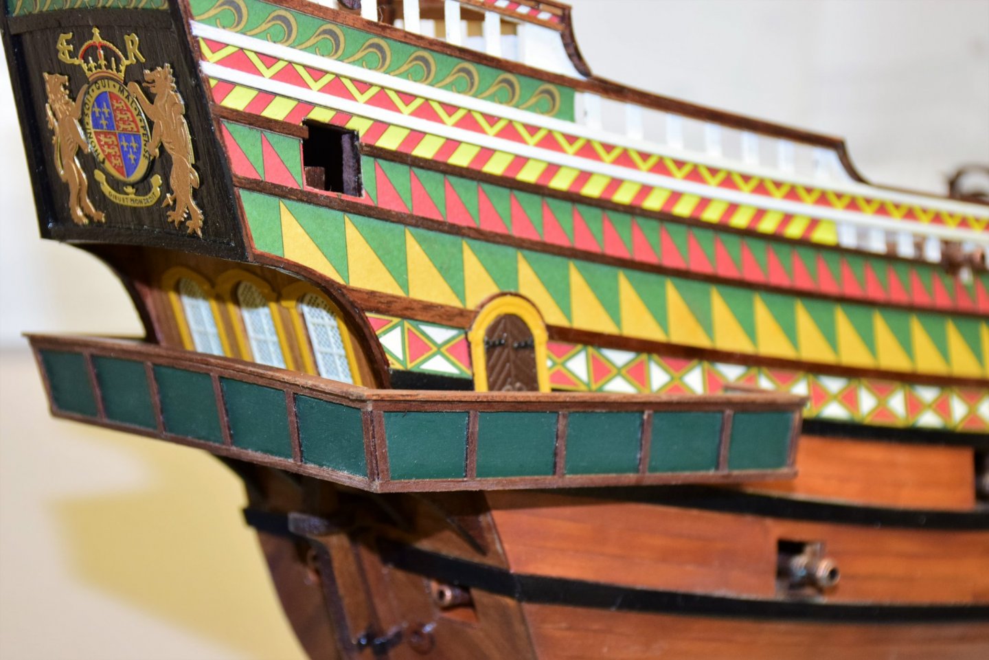
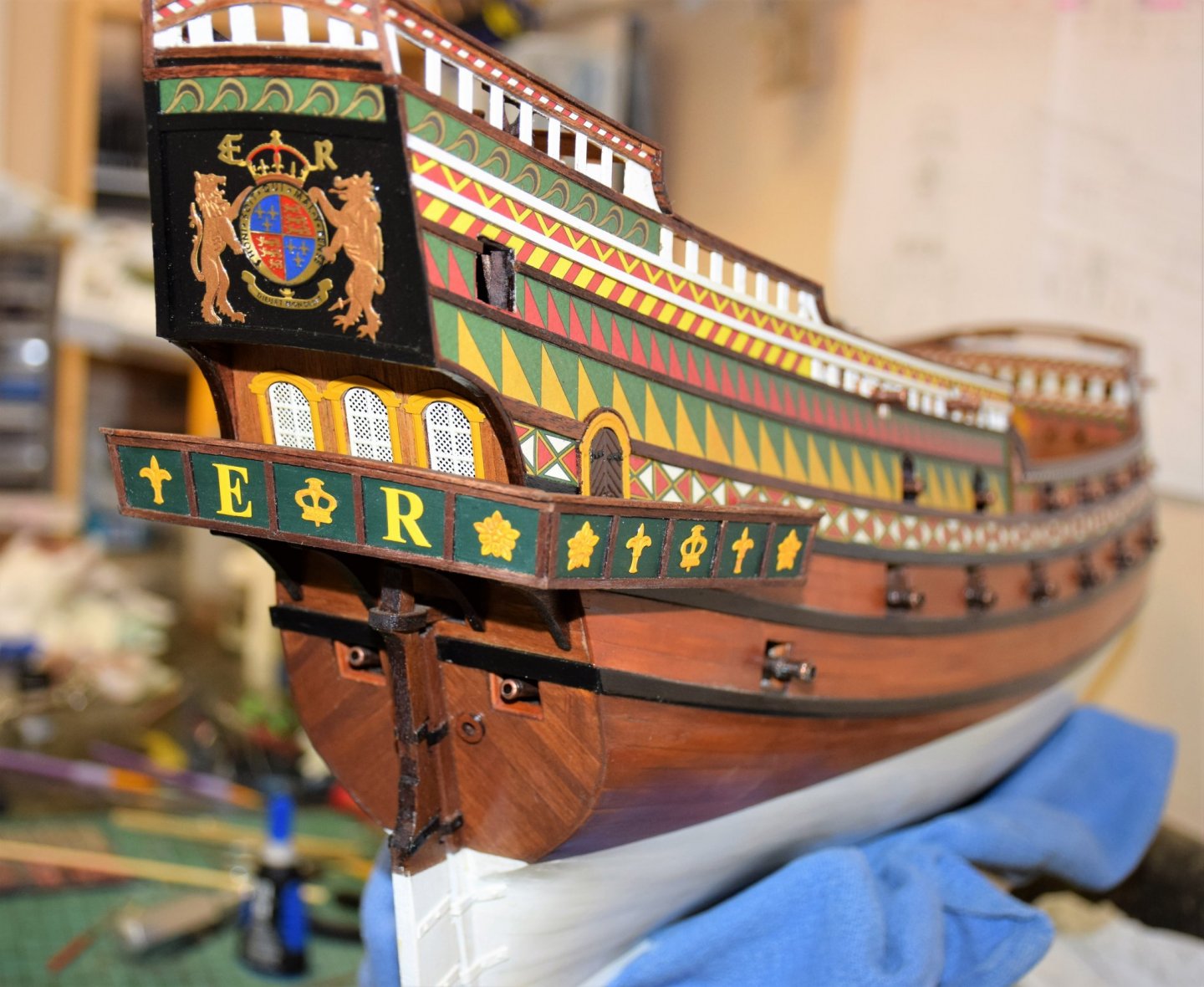
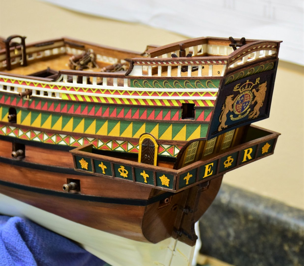
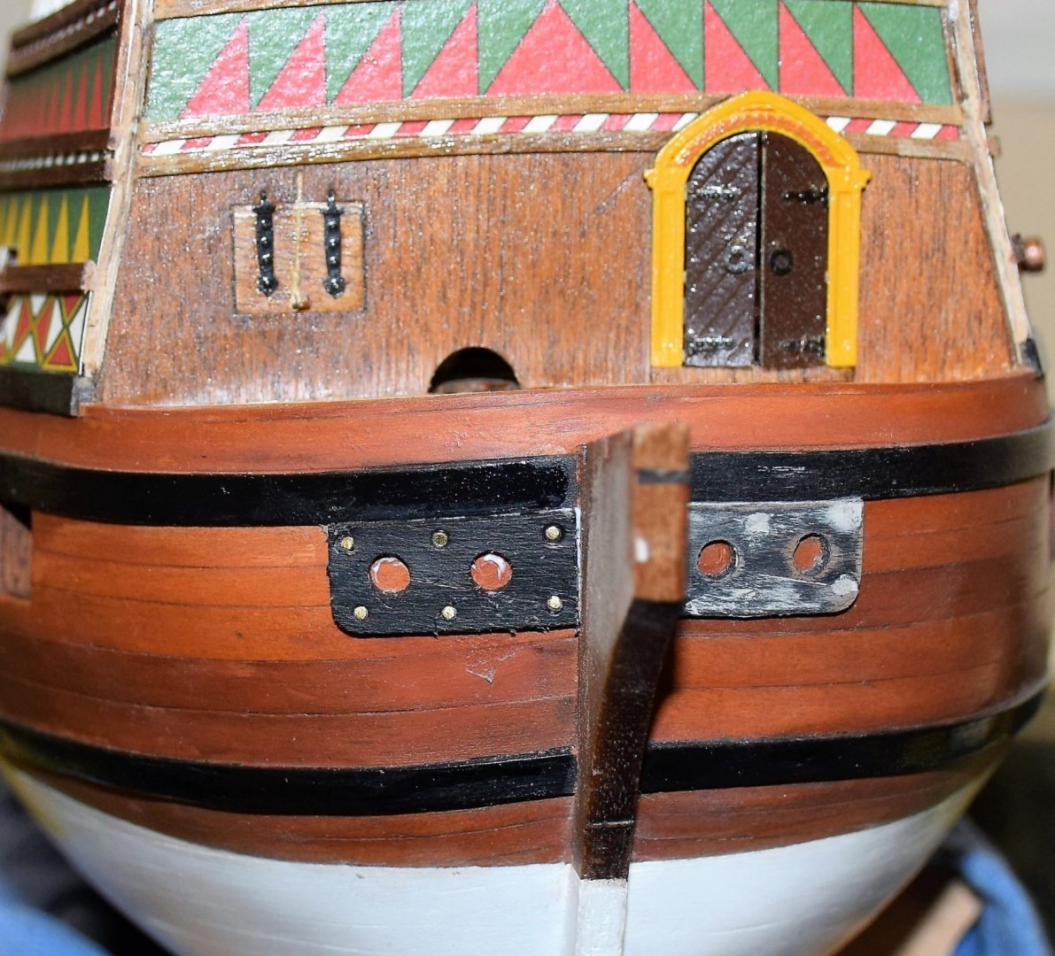
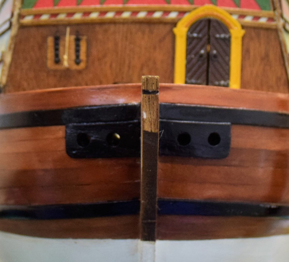
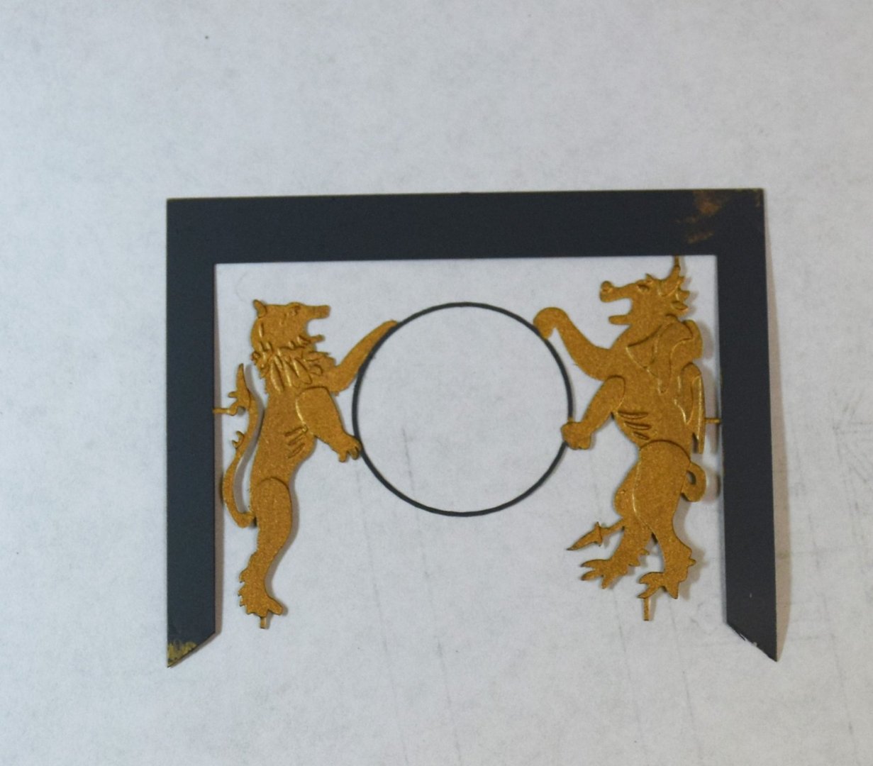
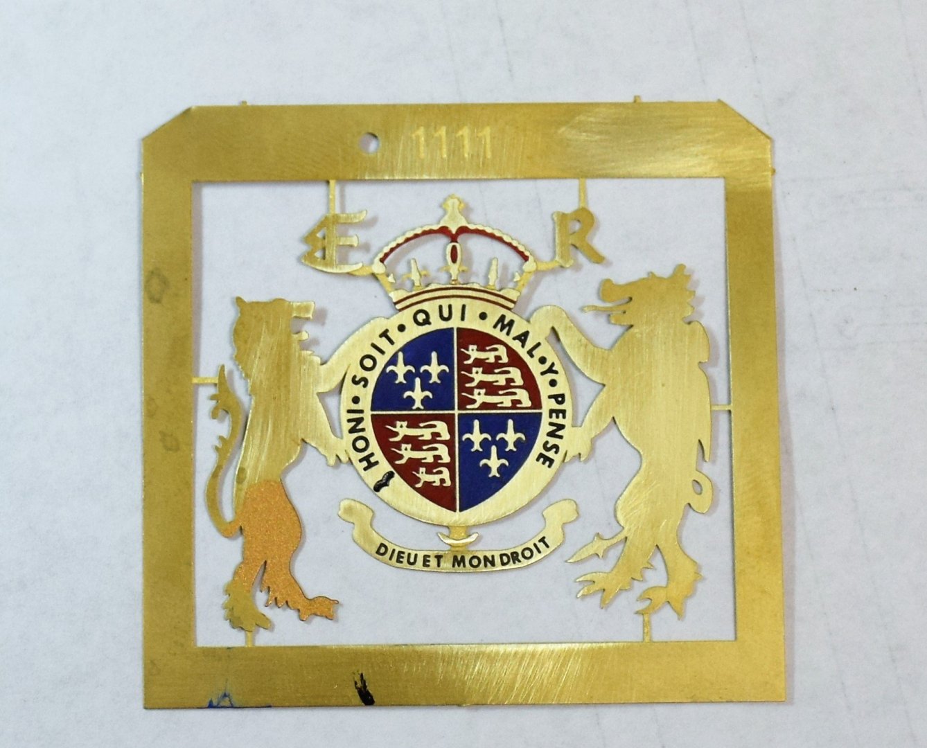
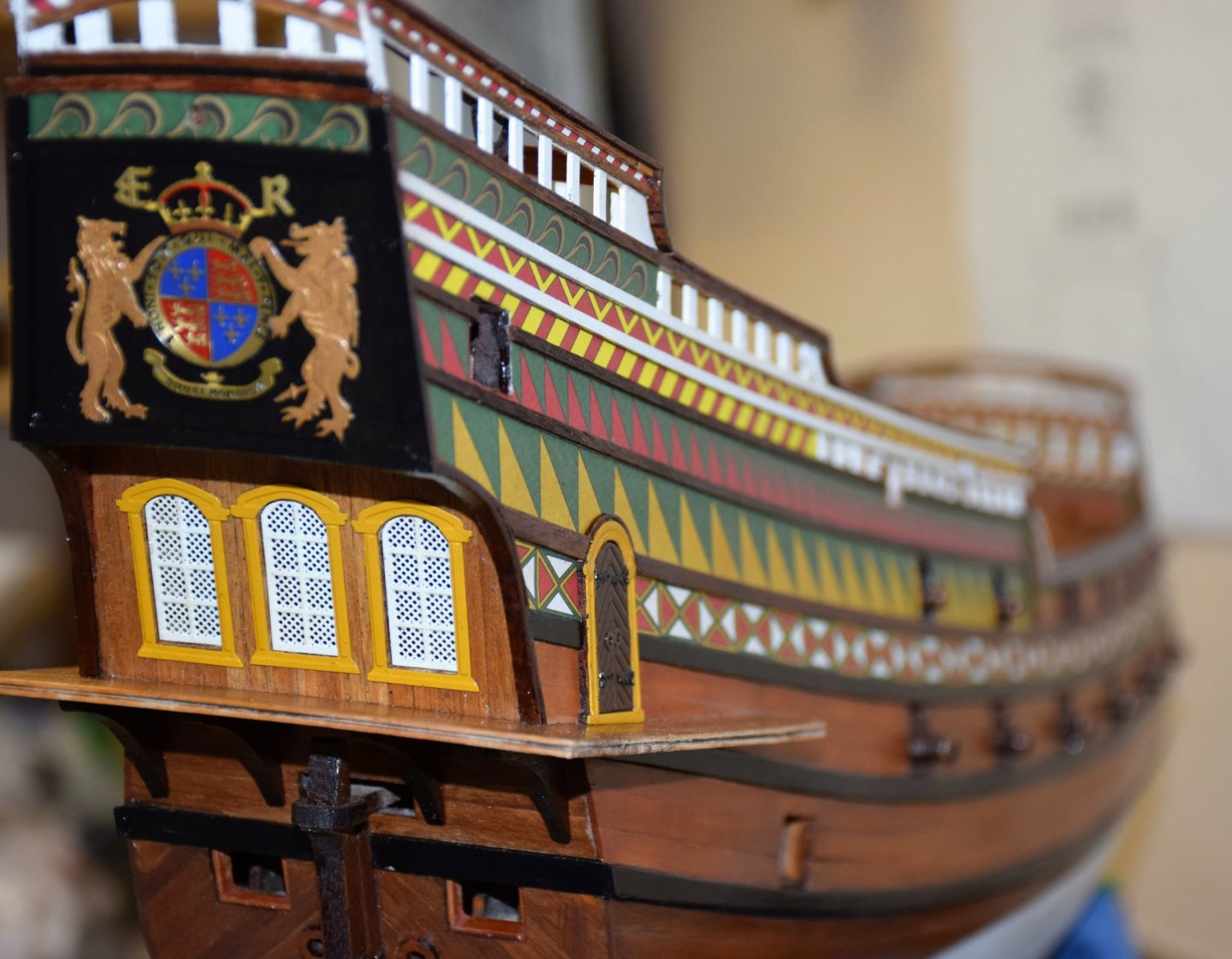
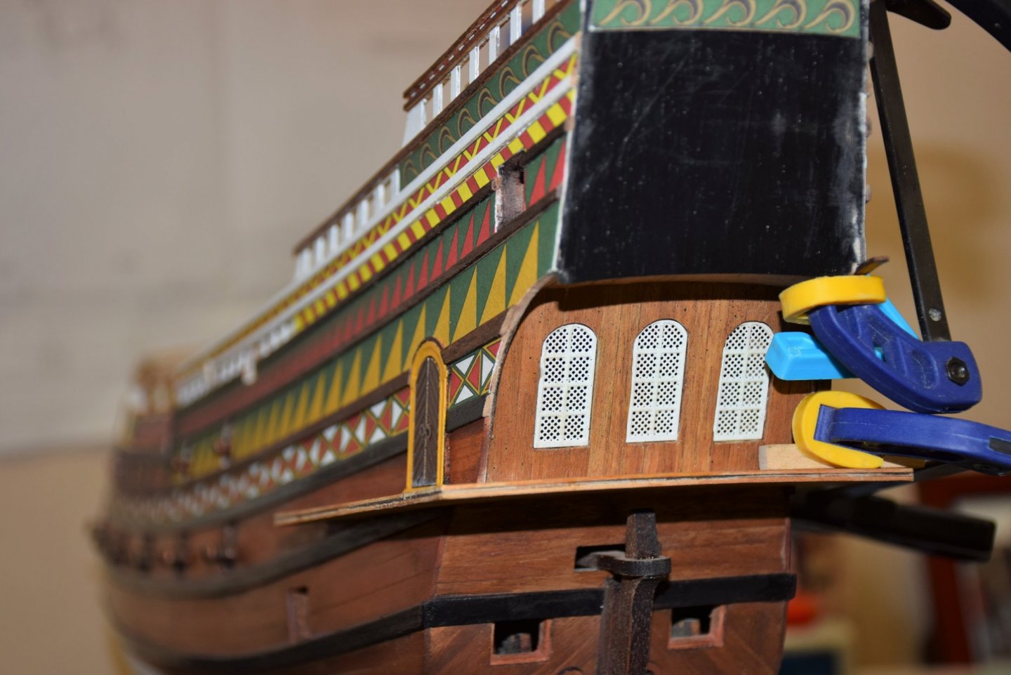
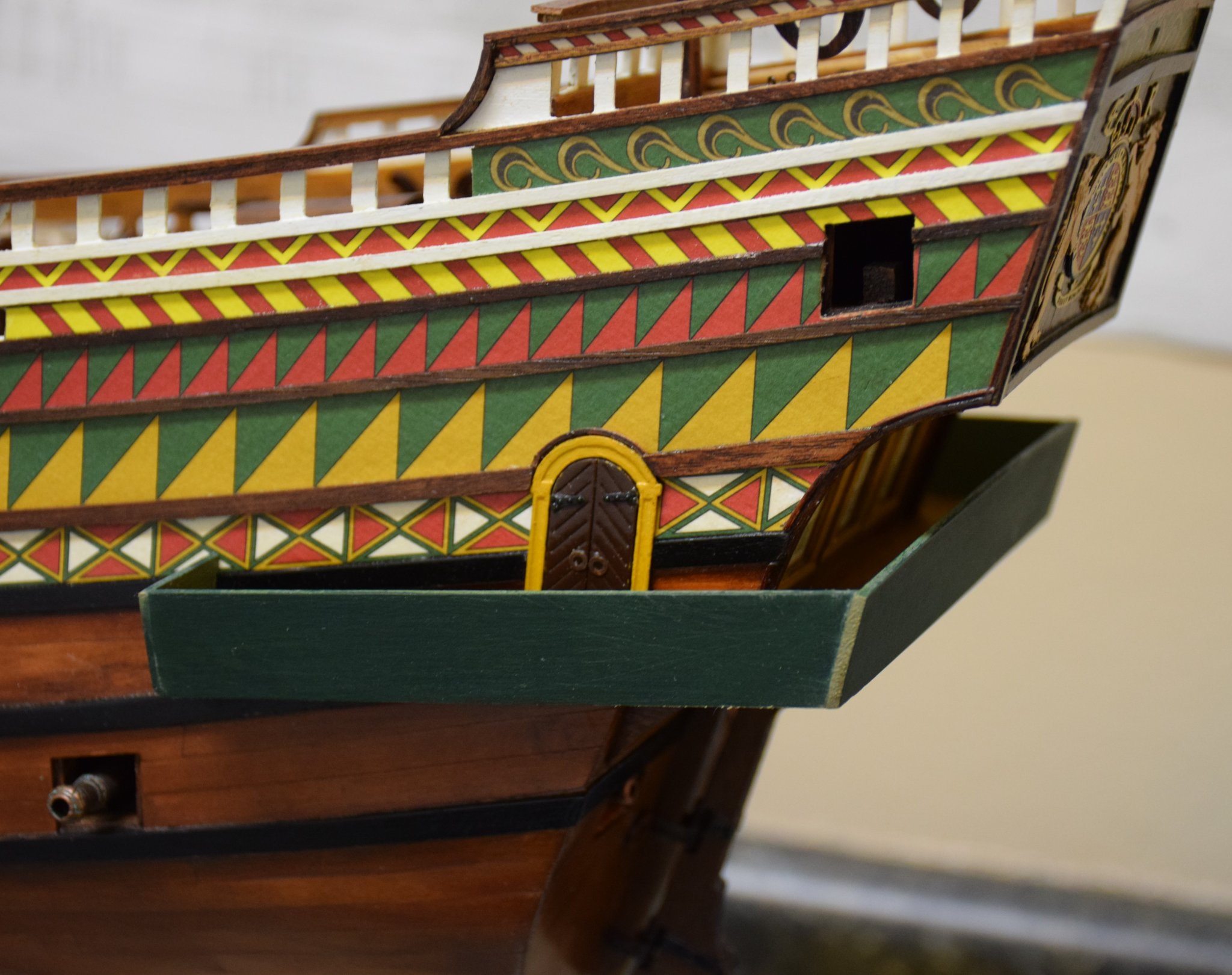
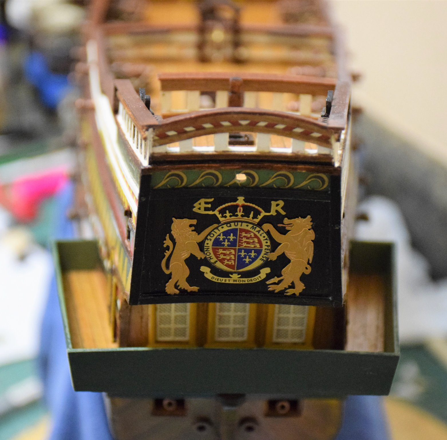
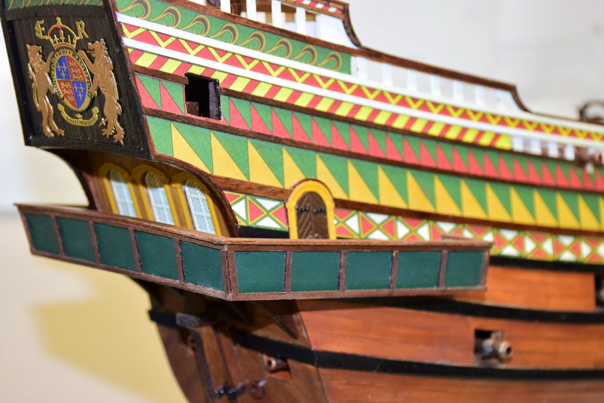
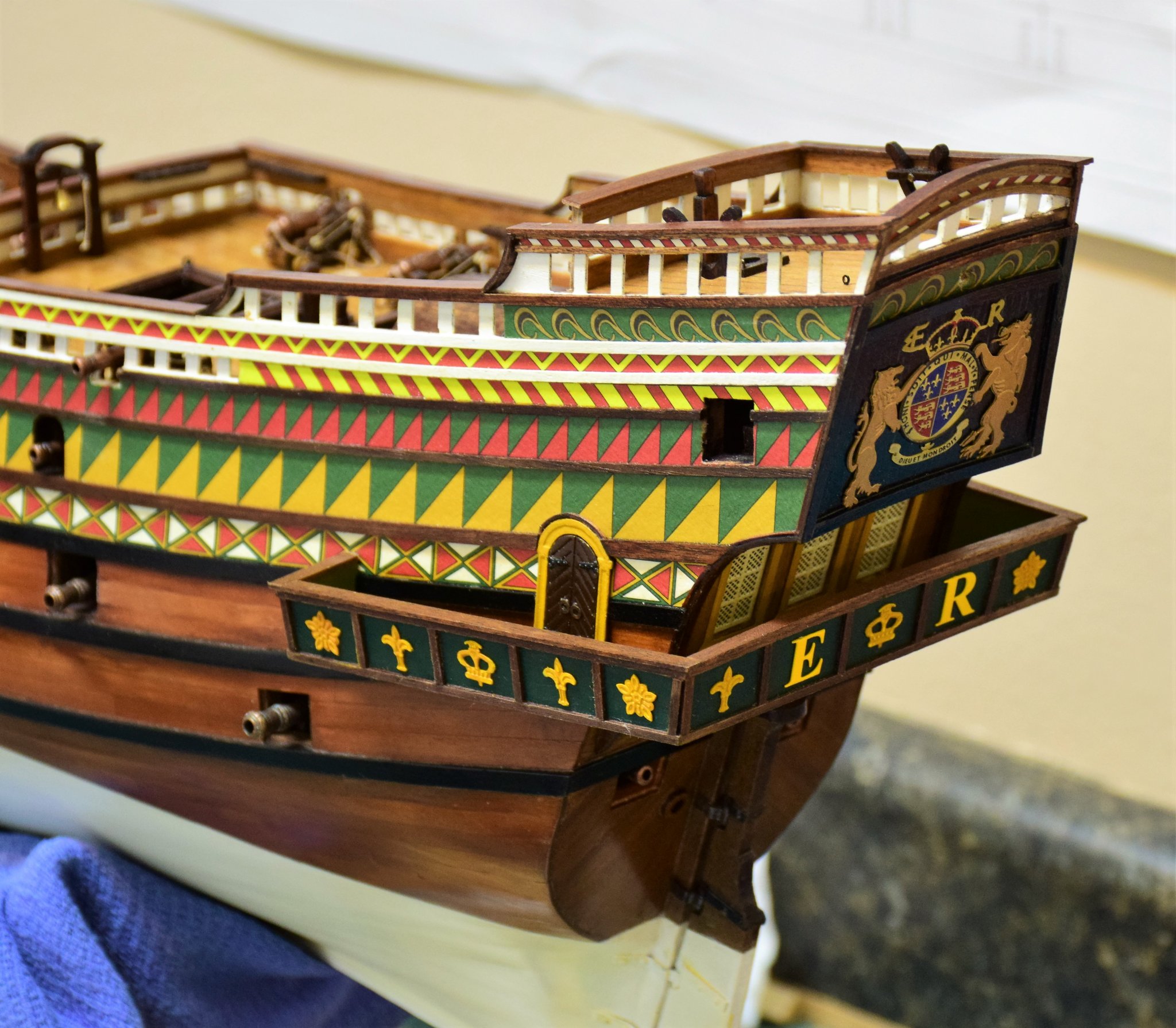
Greetings With the side decorative paper patterns and wales now complete, attention was turned to the stern, which was lined with 1x3 mm strip and painted black (blue arrow). The curved area below the stern board was lined with the same (red arrow). The windows are framed with photo-etched parts painted yellow. The 4 knees that support the rear platform have also been place. Only a slight amount of sanding was needed to get a good fit. The photo-etched crest that goes on the stern is now prepared. There are 2 parts that when glued together give some semblance of depth. The upper layer is 2 lions holding a circle. Lions are painted gold and circle black. I first spray painted a base coat of grey. The parts were left in the photo-etch frames to aid in handling. The lower layer requires painting the letters black and the center crest blue / red. Paint is applied and when dry, a fine grade sanding stick is used to remove the excess paint on the raised surfaces. Lower part of the lion on the left is painted gold. Finally, the 2 parts are glued together and the frame was cut away; the piece then glued to the stern board. Below is the final appearance. Satin polyurethane was used as the final coat. Next up is the bulwark capping rails and one area amidships involving the capping and wales not mentioned in the instructions. Jeff


- 159 replies
-
- 11
-
-
Thanks for the kind words. it has been an enjoyable build thus far Jeff
-
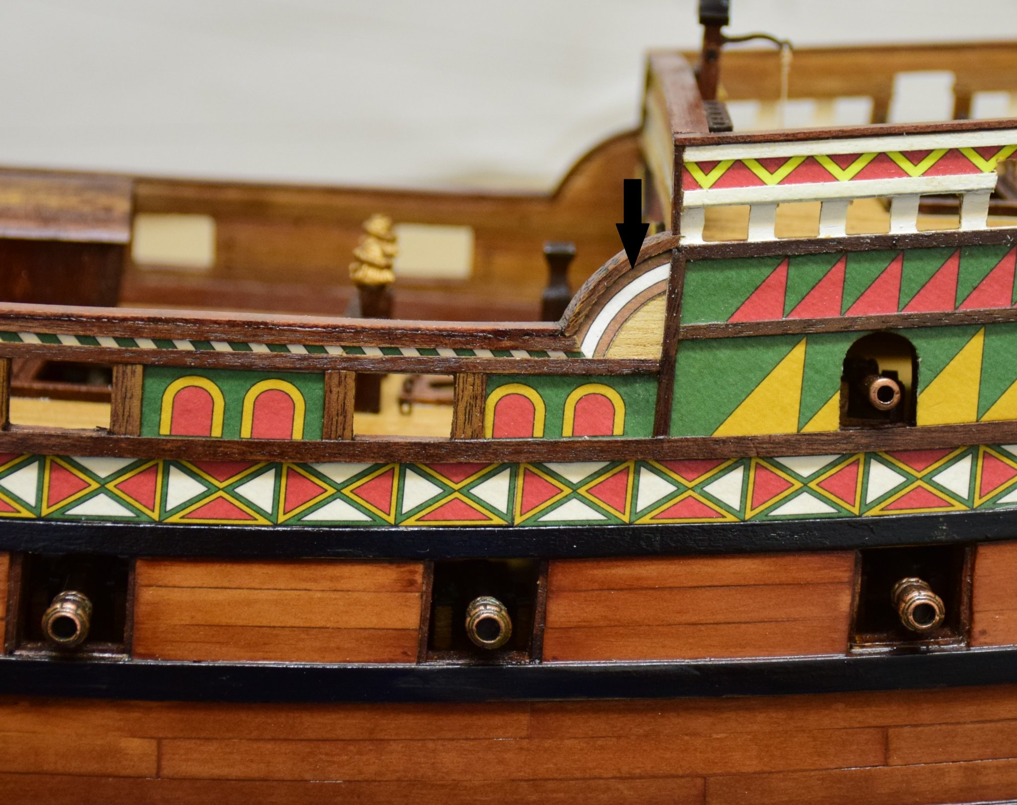
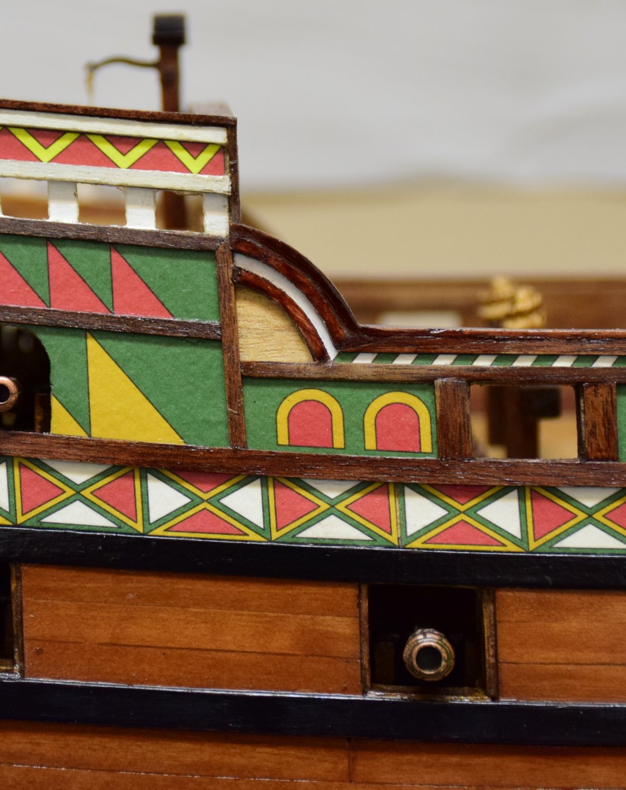
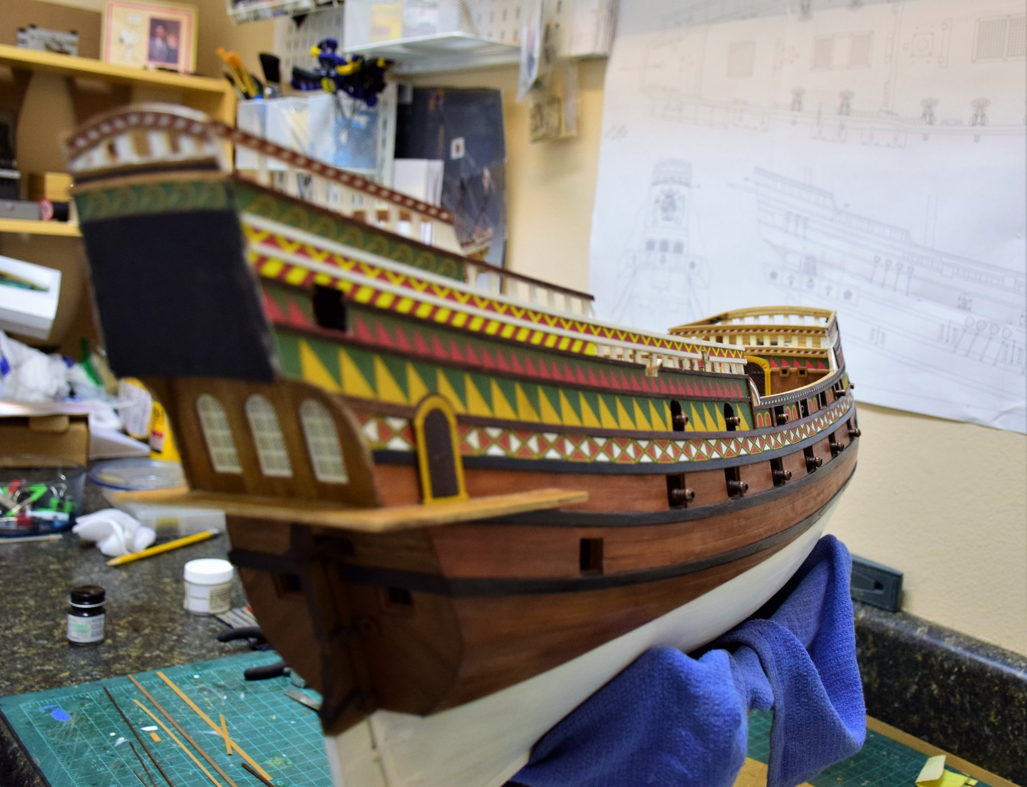
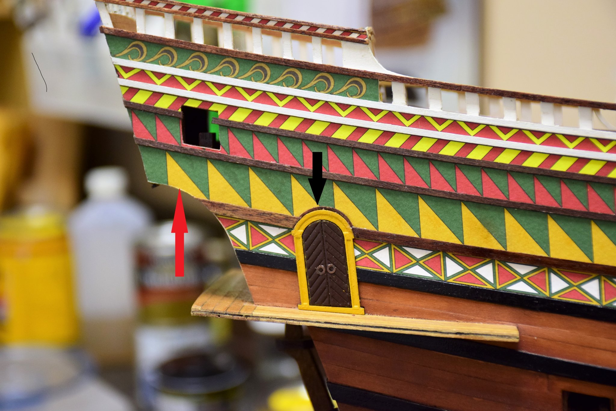
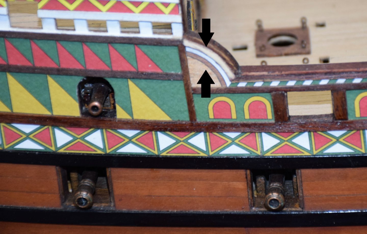
Greetings All of the upper wales are now complete Photo below shows a small piece of wood used to cap the side door frame (black arrow). The red arrow shows where a curved wood strip needs to go (not mentioned in the instructions but visible in several pictures). Below, one strip clamped in place. Several planks will line the stern board - more pics to follow when that is complete jeff


.JPG.39fff20a73c857bf8f5be8dad9e7c5d4.JPG)


.JPG.1c671a5f01680c753cf93722ac8b6df6.JPG)