Richard Feliciano
-
Posts
48 -
Joined
-
Last visited
Content Type
Profiles
Forums
Gallery
Events
Everything posted by Richard Feliciano
-
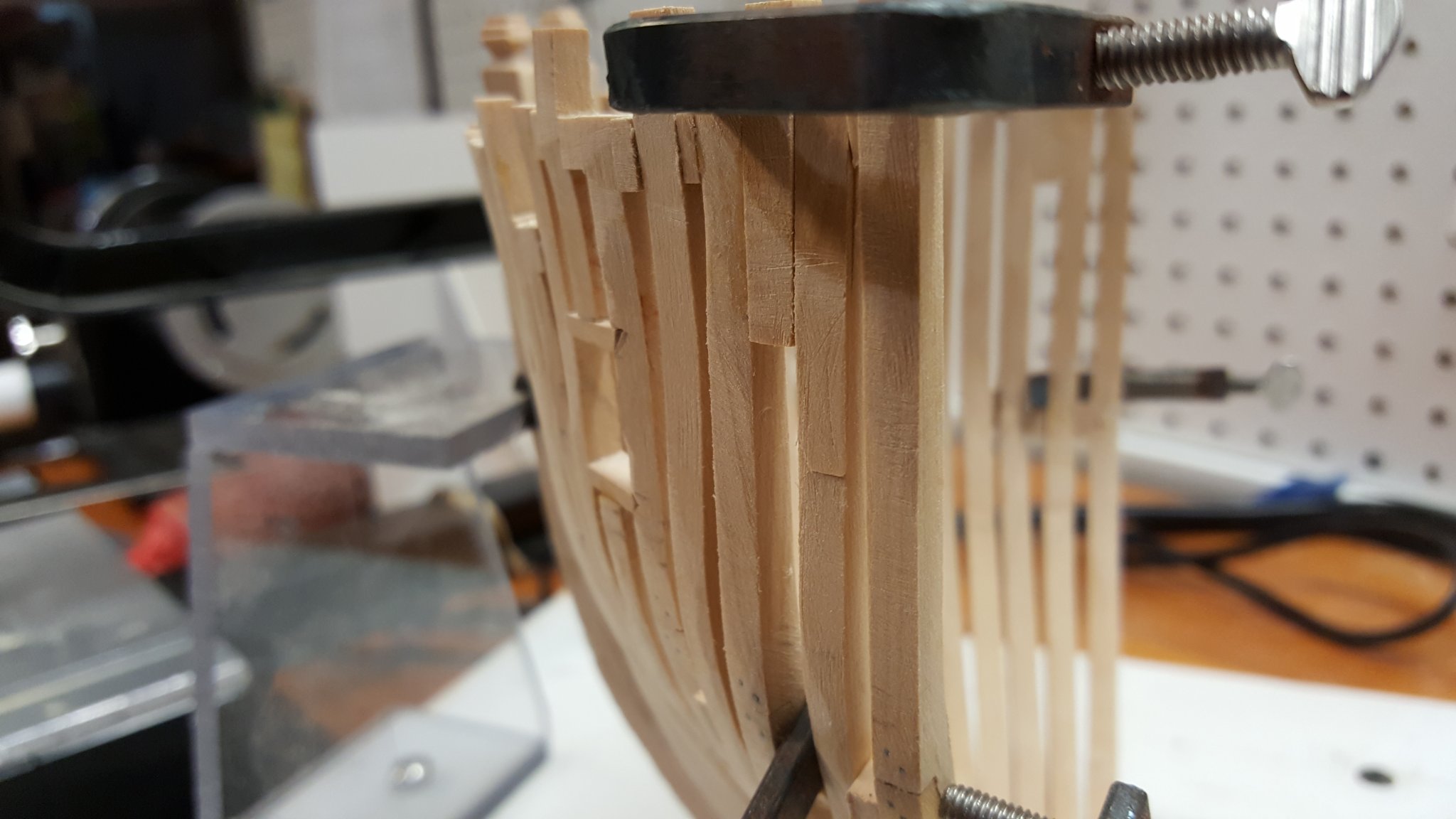
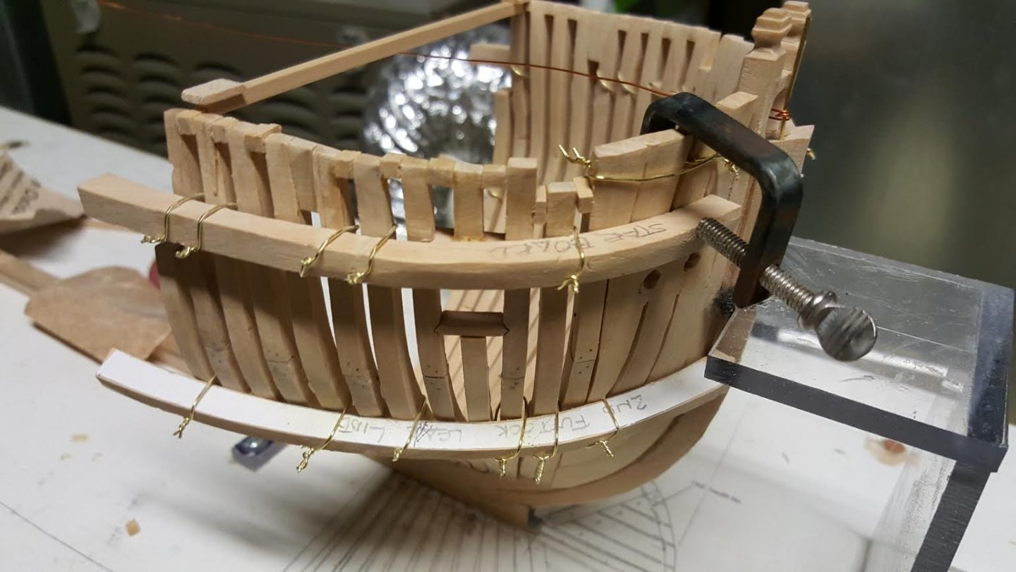
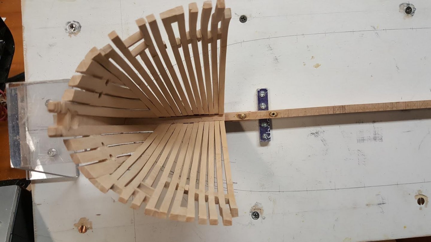
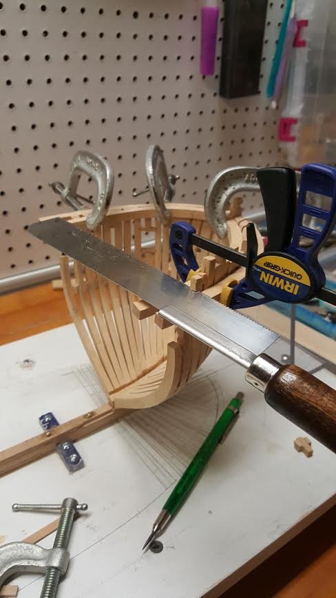
After installing bow frames ( 2 thru 12), I began shaping the frames to the required curvature and dimensions. I discovered the frames were severely out of alignment. The procedures set forth within the Sea Watch books for setting of the frames were not accurate for my skill level. I had to resort to constructing heavy form patterns at the deck and 2nd futtock lead line levels. Using these patterns, I wrenched the frames into their proper position using tie wire. I also ran a centerline wire from bow to stern. A spreader bar was installed at frame 11 using the X Section NMM plan. If this same exercise is to be done in the future on another model, I would construct external framing patterns to lower the frames against. There are other modelers using this technique. Attached is a photo of what I performed. I've lost several weeks addressing this issue. I'm reluctant to remove the tie wire for some time until the re-bent frames set into their final position. The frames are wetted down daily hoping they warp into the correct positions.
-
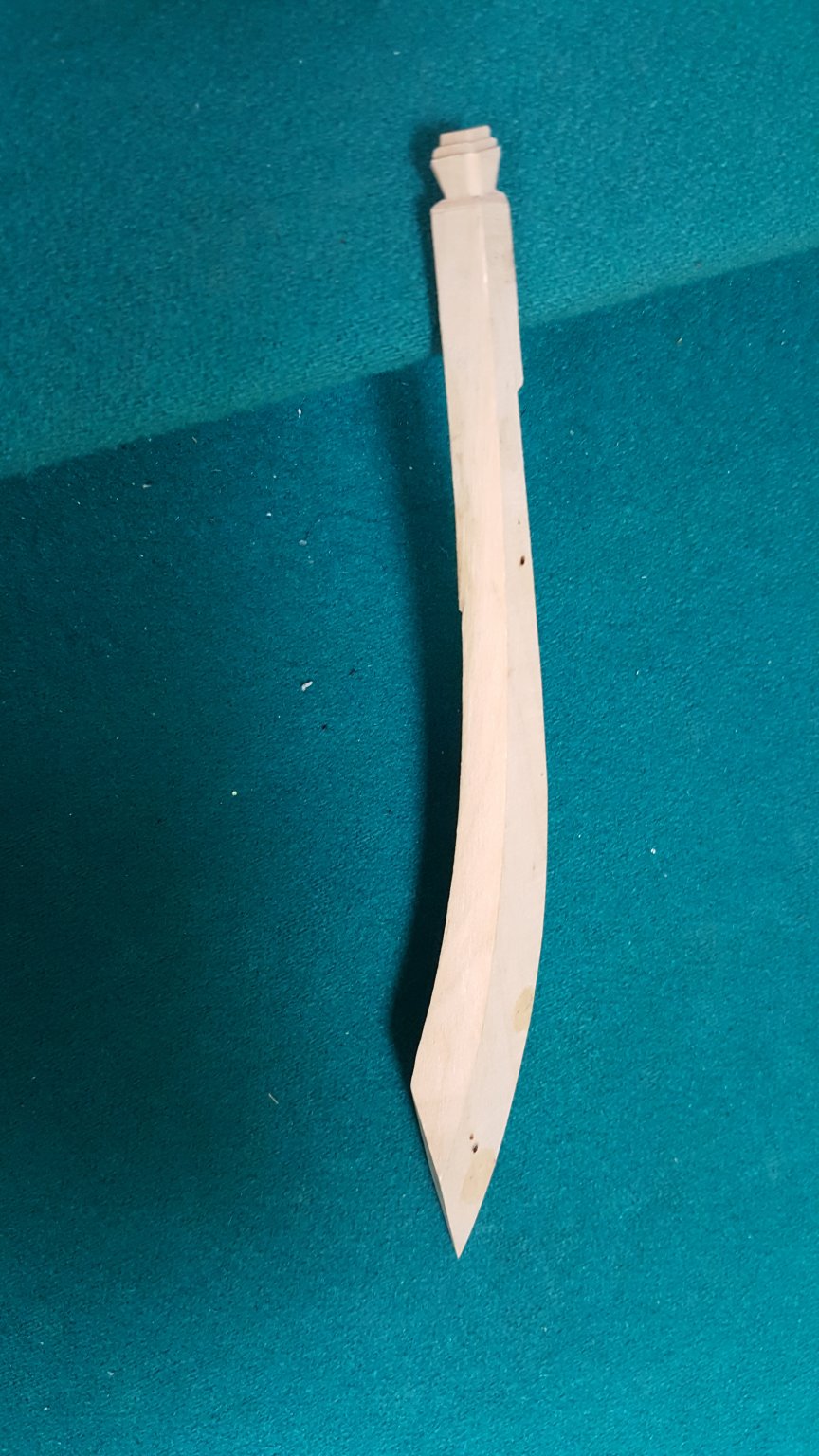
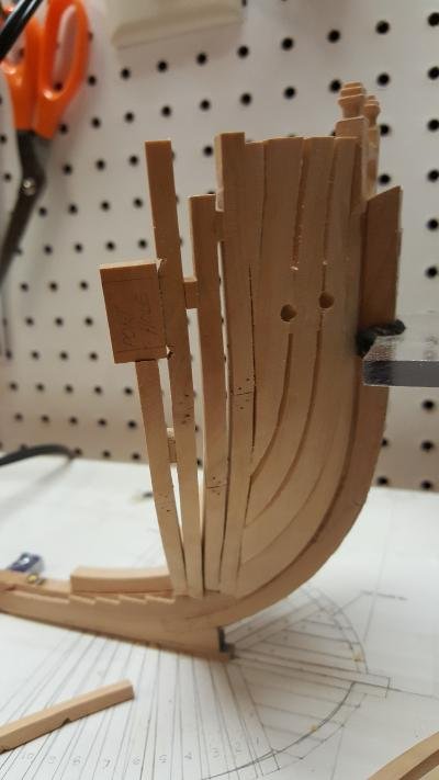
Update on my Frame Thickness issue. I reduced the top of frame thickness to 6" on the bow. Attached photo shows before (top of photo) and after (photo bottom). As you can see, quite a bit of material was removed. Looks a lot better.ved.
-
I'm building the Swan Class Sloop HMS Fly. Using your description nomenclature, the moulded dimension of the top of frame is what is needed The general consensus is 6" is what is to be used. This checks with my NMM plans. 6" is thin! A lot of sanding is going to be required. I plan to construct a rigid template based on the NMM Deck Plans to assure the proper location and orientation of the top of frames.
-
I look at this part of the frame above the deck as a cantilevered column loaded on hull exterior by wind, waves, canon balls etc. This part of the frame extension above the deck is in tension on the exterior and the interior portion is in compression. The depth of this beam-column is the distance from the extreme tension fiber to the extreme compression fiber of the frame (i.e.-the beam column thickness).
-
I like your bow cant frame forms. Should help in setting of the frames. Hope you've recovered from your accident.
-
I'll go with the 6". I'm going to fabricate the top timbers separately. I assume they will be 8" thick to be flush with the ship hull.
-
Having an issue with the top of frame thickness for the ship frames. After cutting the frames down to proper height, the frames need to be reduced to the thickness indicated on the NMM Upper Deck Plan. This seems to be abnormally thin. After conferring with Greg Herbert, he suggested the frames may be only 6" thick at deck level. This will require a lot of sanding to achieve this thickness.

-
Stuglio, You have the same issue on your model as is occurring on my construction. The stepping line on the deadwood does not match up with the frame layout pasted on the building board. The steps are a little wider than 2 each 9" frames. As the frames are erected, a little creep occurs. By the time #12 frame is erected the base of the frame is about 2mm off frame building board location. (You can see this clearly. In your 1st photo). I ignored this issue while erecting my frames. While the base of the frames off, the tops are held true to building board location with my square.
-
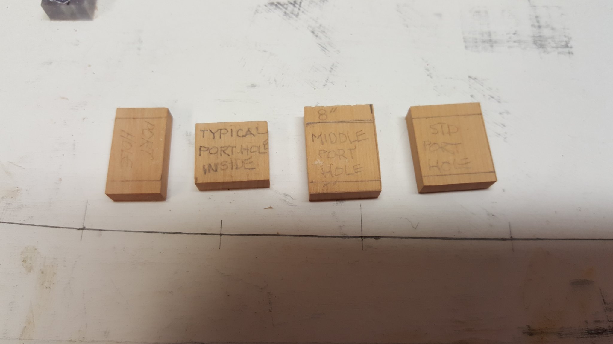
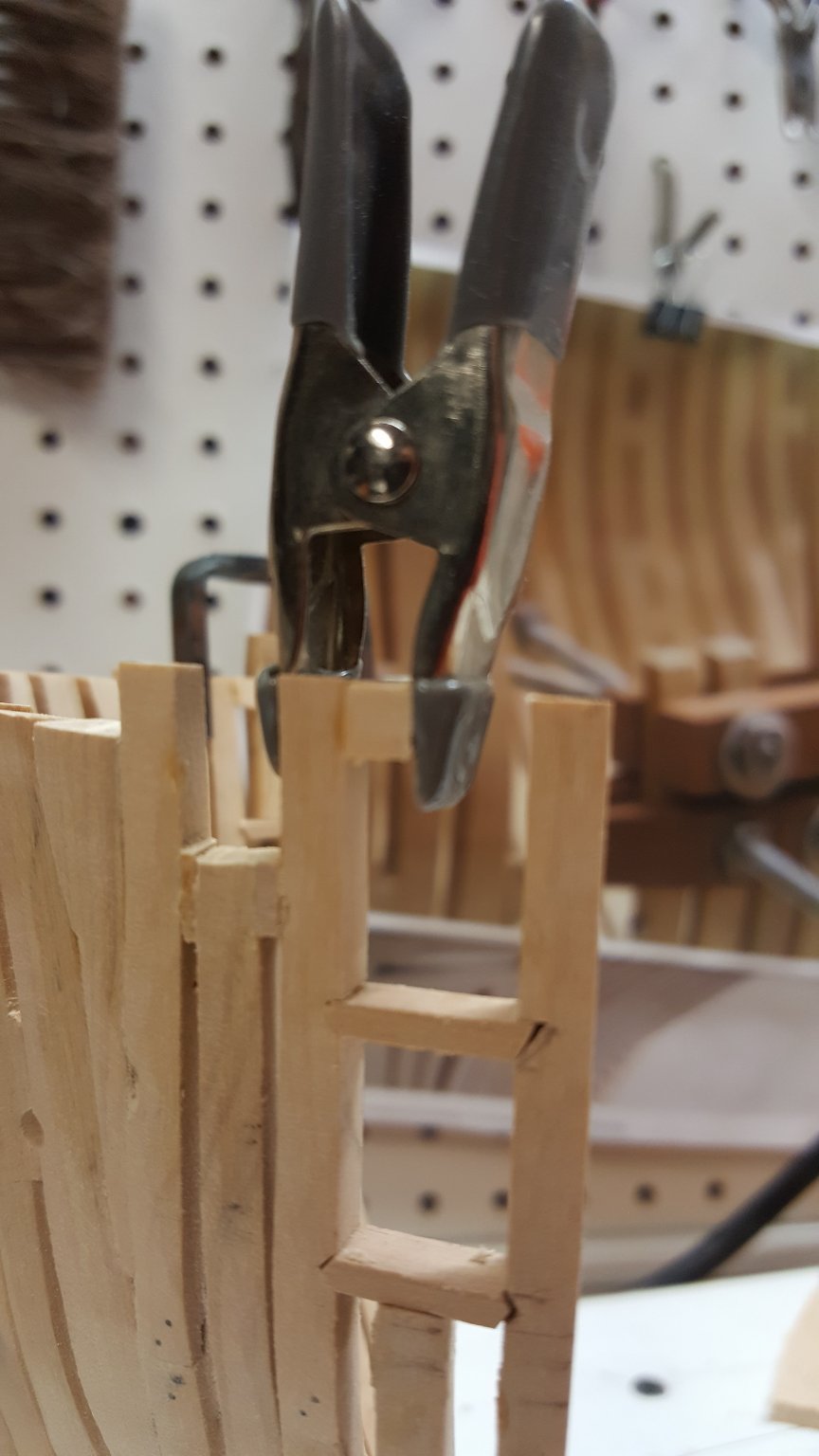
Additional photo showing use of porthole template. Notice frame 3 has been trimmed for cathead at this stage.
-
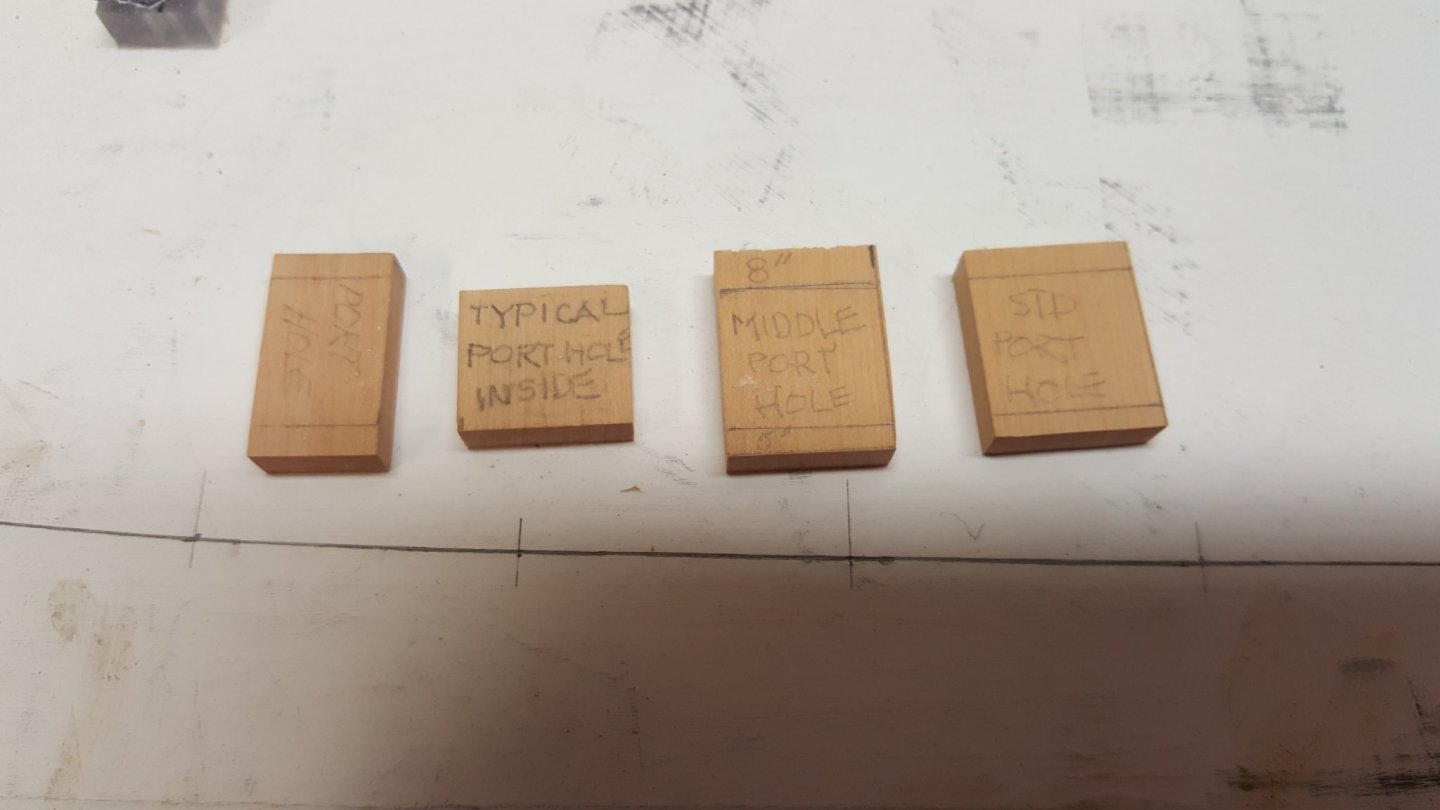
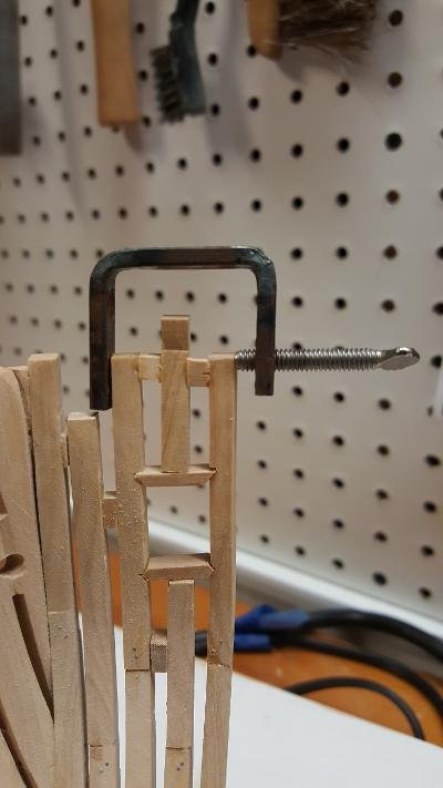
My take on porthole construction: 1. I like the approach of previous posts that used templates for the construction of framing about the portholes (see photo) 2. First I cut the sill slots on one frame only. 3. I trim the next frame (base of sill using the template to determine where to cut. 4. Temporarily setting the outside frame against the sill base, I mark the cut positions, remove the frame and perform the sill cuts. 5. I set and glue one frame spacer into position and clamp (see photo). 6. After the glue is set in step 5, I glue the short frame upright over the middle of the sill and the final spacer into position. I use home made clamps fabricated as described on p.44 of "The Anatomy of Nelson's Ships" by Longridge. I find these clamps to be the most versatile. There is some conflict with the frame positions on the building board, but I chose to use the positioning dictated by the templates which conform to the NMM plans.

-
I'm not a big fan of .jpg. Too long a time to transfer files. If viewers prefer .jpg, I will attach in that format.
-
Working on this model for about a year. Made many mistakes but still plugging along. Admiralty workshops that I have attended in the past have helped a lot. The Sea Watch books covering the construction of this model are indispensable. Bow Framing 2 Sep 2020.pdf Bow Framing Sep 2020.pdf Stern Framing Sep 2020.pdf Swan Typical Frame Assy.pdf
-
Good fine files is the only way to go
-
HMS FLY by cafmodel - 1/48
Richard Feliciano replied to cafmodel's topic in - Build logs for subjects built 1751 - 1800
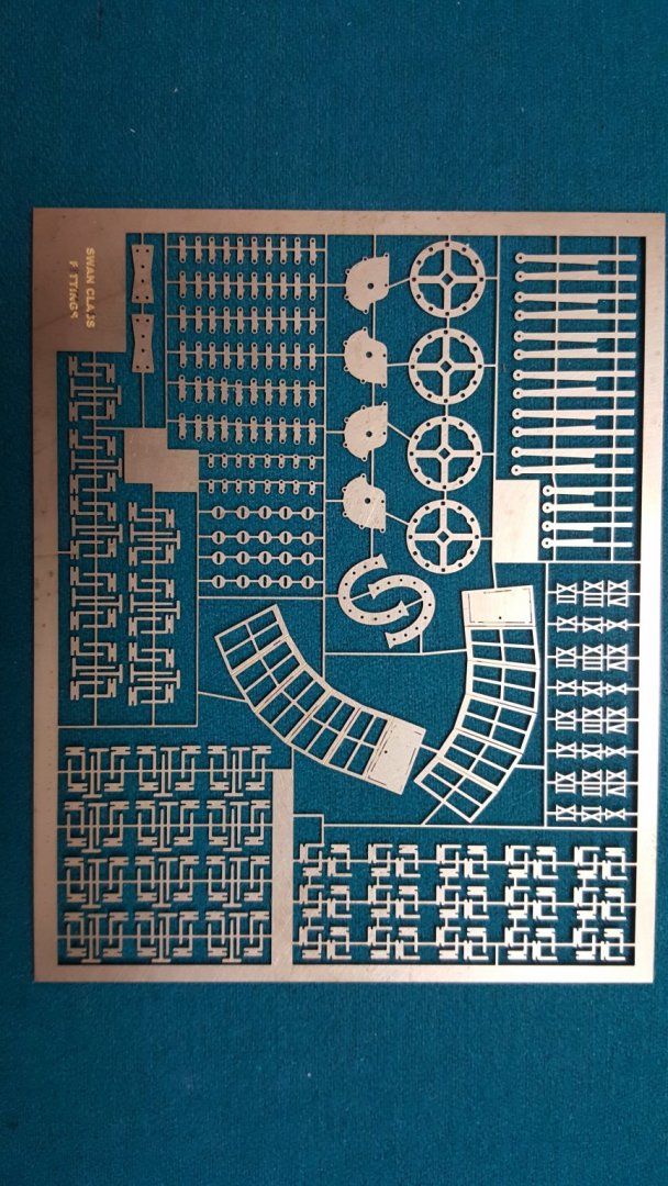
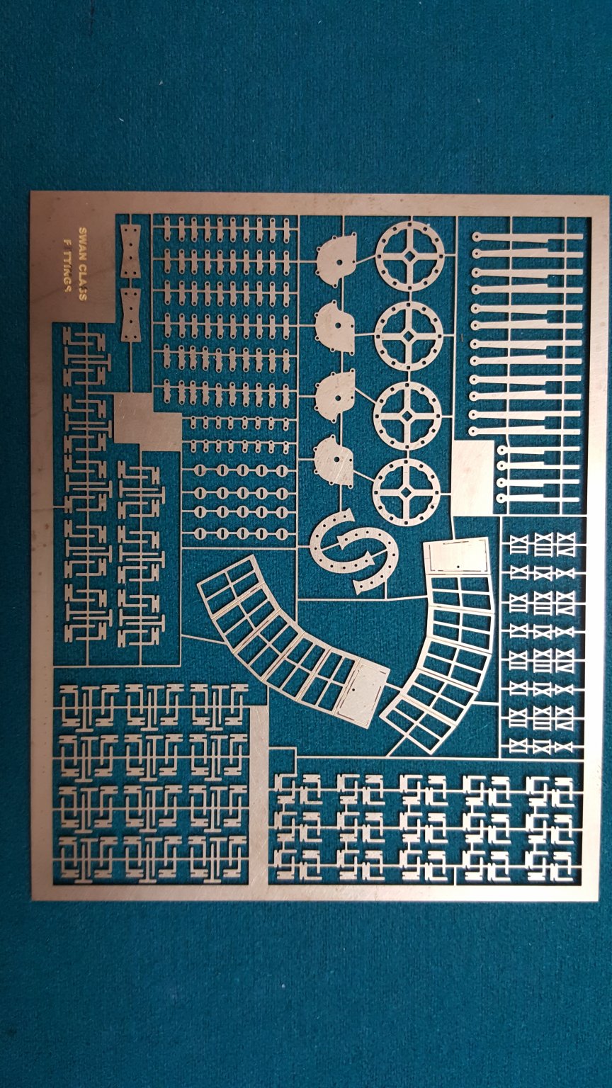
I too am constructing the Fly. Observing your sketches, the frames in the stern have steps at the top. Do you have copies of the Sea Watch books by Antscherl? I have enclosed a copy of the photo etched details if you are interested. I have extra copies.