HOLIDAY DONATION DRIVE - SUPPORT MSW - DO YOUR PART TO KEEP THIS GREAT FORUM GOING!
×


JohnU
-
Posts
170 -
Joined
-
Last visited
Content Type
Profiles
Forums
Gallery
Events
Everything posted by JohnU
-
 Thanks for the nice comments. It's been a long time getting to this point. Almost done with the deck fittings!
 -
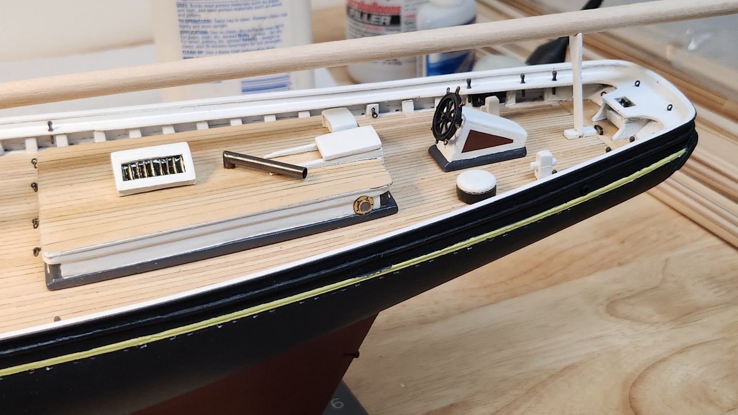
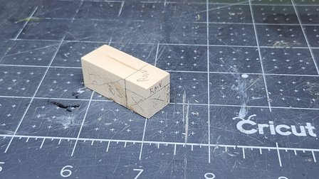
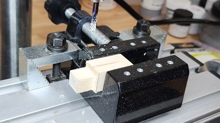
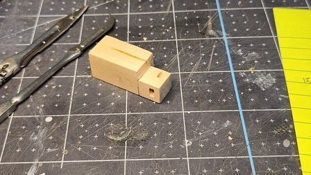
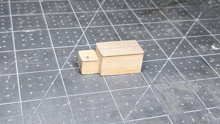
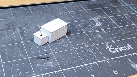
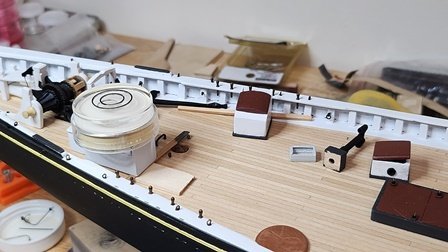
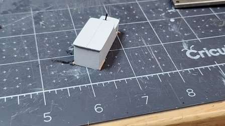
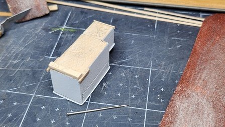
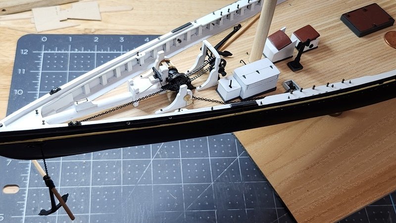
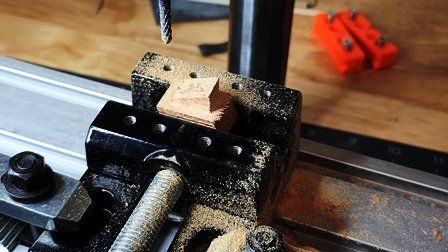
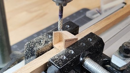
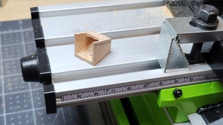
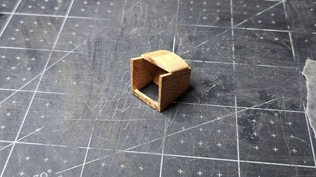
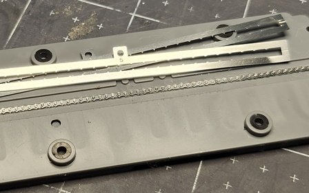
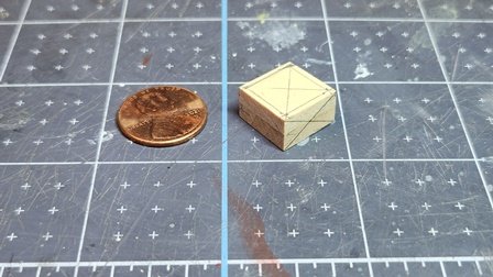
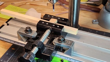
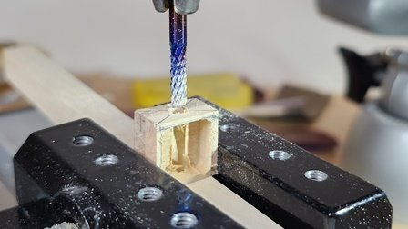
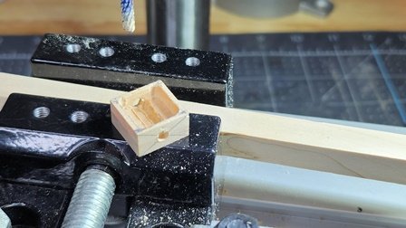
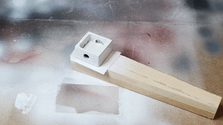
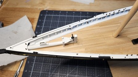
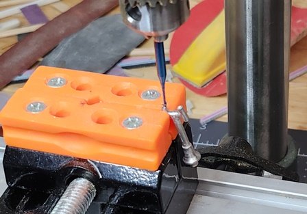
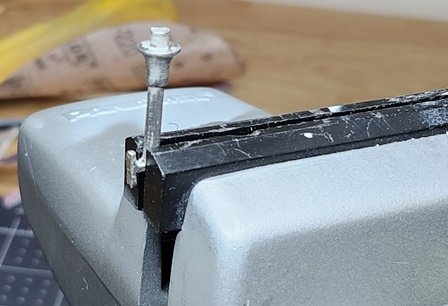
The engine box is a more complicated structure. It's really two boxes and has a number of details. Once again, to simplify construction, I started with a solid block. The block was cut to rough size and sanded to finished size using a disc sander. The layout for cuts to make the smaller box was marked. A mill was used to remove the waste material. A mill was also used to cut the slots for the clutch lever and drive shaft. The slots were then squared off with a fine square file. A thin piece of wood from some of the dory scrap was used for the top of the motor box and drive shaft box. A scalpel was used to score lines in the boxes to simulate separate boxes, top door and removable side panel. The boxes were painted and a blackened brass flat installed. The usual process; sand, shellac, fine sand, primer, sand, airbrush finish color. Brass Black was used to blacken the clutch lever. The lever was sharpened on one end and inserted into the slot using a pin-pusher. The motor box is far forward where there is significant slope to the deck. This means the box must be on a level platform. To determine the correct slope a bubble level was used to first level the ship. The level was then placed on top of the motor box and shims added to bring it level. The necessary thickness could then be measured from the shim stack. Temporary coamings were added to provide a spacing reference for the finished coaming. The correct thickness shim was added to the aft end of the box. Coaming pieces were then glued around the bottom using the temporary guides. After the glue set a line was marked and a scalpel used to trim the slope into the coaming. While waiting for the glue to dry, some thin brass strip was used to make the hinges. These things are really, really tiny and hard to hold while filing to shape. A small hemostat seemed to work best. Finicky work. Lost one of the hinges twice. A tiny dab of PVA was applied where each hinge goes and the hinges cemented in place. Magnifier and tweezer work here. Next the coaming was masked off and trim color applied. After the paint dried the motor box, chain box, companion way, skylight and galley stack were cemented to the deck using PVA. My anchor chain arrived a couple days ago. I blackened the chain with Brass Black and added it to the ship to get the full effect.
-
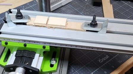
The forward companionway was next. The photos of the original ship were used for construction and the plans scaled for size. A small block was cut to size and squared off using my X-Y table and drill press technique. Note: a harder wood such as boxwood or pine is much easier to get a precise cut. Next a line was drawn on the side of the block for the slope of the top. A second line was drawn 2mm parallel with the first. The block was clamped in the vise along the second line. This allowed the mill to cut all the way to the edge of the block. The waste part was then milled off. The front half of the box was hollowed out, then the box was rotated to make the slope perpendicular. The back half was then hollowed out with the mill. Because the bottom of the box was cut out, a black paper was glued to the bottom of the box using the same technique as the skylight. To make the rounded cover I sliced a small piece from an appropriate size of dowel. In this case an old closet rod was just right. The back of the interior and inside bottom was painted flat black, the top burnt umber to match the skylight and the rest white. The coaming was added and painted to match the other coamings. I didn't quite like the way it looked with the opening. I added one of the boards that close of the hatch when it's not in use. That, of course, would not be the way it was actually used but looks much better.
-
Thanks Gregg! Your comments are appreciated.
-
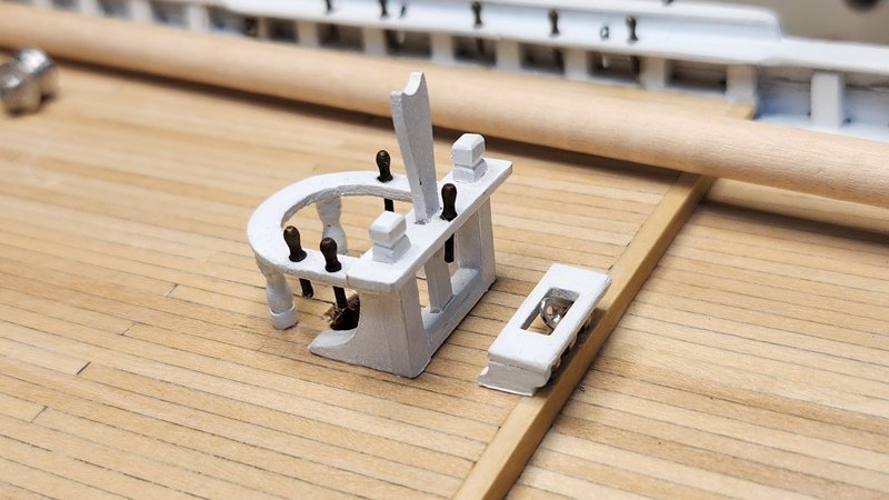
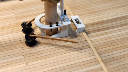
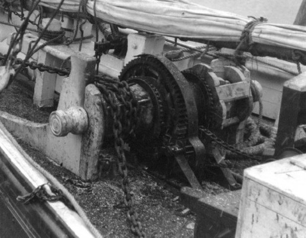
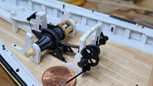
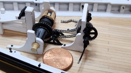
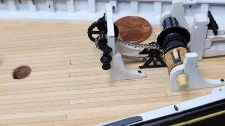
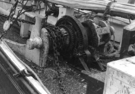
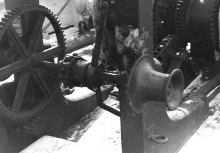
Although it's not on the plans, photos show a guard for the windlass gear and it's counter gear. In the early days of machinery there was not a lot of thought given to safety. It may be the ship was built without the guard and it was added later after a mishap. That was added to the model along with the quadrants and simulated shackles. The side plates of the chain were also painted with flat black. The original pawl for the windlass was missing. I'm waiting for that part from Model Shipways. The jumbo jib horse and formast/mainmast eyebolts were added at this time. The machinery is cruder than I would like. That's a limitation of the castings. Plus I would have to invest heavily in machine tools to make better ones. Or, as discussed previously, print the parts. While not perfect, the machinery adds pleasing detail to the model at viewing distance.
-
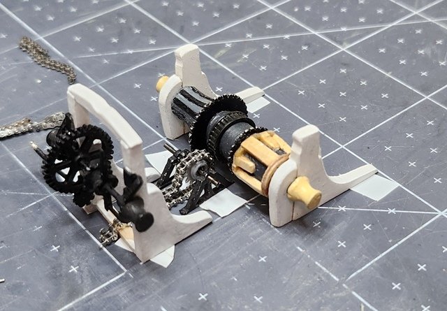
The machinery is mounted. The dimensions on the drawing were pretty close. The boom crutch needed a little adjustment. There's a certain amount of fudging due to the crudeness of the parts. To make the parts sturdy I put locating holes in the supports and deck, then placed pins in them. I had previously left the bottoms of the windlass, boom crutch and counter gear supports unpainted. PVA was used to cement them in place. Some touch-up was needed after handling them extensively while positioning. Because the machinery is non-operating, I was able to simplify installing the chain. Normally a chain has a master link inserted to tie it together. At this scale that would be very difficult. As it happened the chain broke again during installation. Luckily, it broke at exactly the right length. That saved another chain repair. To tie the ends, they were placed as they would lie on the sprocket and glued in place. the sprocket was then rotated so the glued ends were out of sight. I put a little CA on the other sprocket just make it more robust. The chain droops very realistically. Just like the photos. There is still the guard on the gears, the quadrants and the windlass pawls to install. I may also paint the chain side plates. The real chain would not have been shiny like the roller chain. That will also make the chain a little sturdier. Then it's back to cabinet making.
-
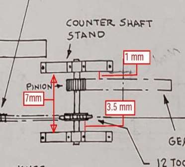
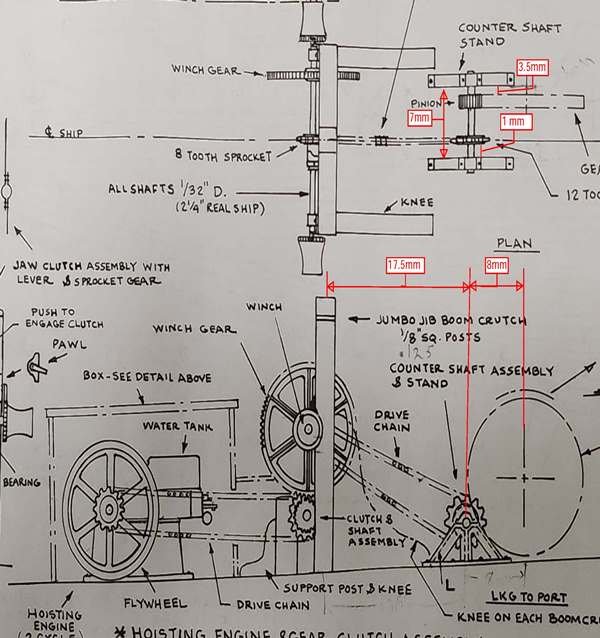
Quick Note; I incorrectly reversed the counter shaft gear spacing. Here's a corrected drawing:
-
Hi Hermann, Probably not. I'm using the provided part. It's not suitable for adding the handles. They would be like wire at that scale. They do look pretty. Too easy to damage. RetiredGuy is doing them I think. His whole setup is functional, including the pawls and clutches. He has a reproduction of the engine to go in the engine box which opens. Maybe he'll rig a an electric motor to run it. Here's the page where he built the machinery: https://modelshipworld.com/topic/22010-bluenose-by-retired-guy-model-shipways-scale-164/page/7/ Where did you get the drawings? They look familiar. John
-
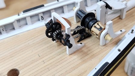
While I'm on the machinery track I decided to work on mounting the windlass and gear train. The sprocket that came with the chain set is the right size for the counter shaft sprocket. Much better than the supplied part. The axle hole was too large though. I filled it with epoxy and drilled it to the correct size. Once painted it will look great. There's some head scratching to be done getting the position correct. After scaling the drawing details and doing some calculations I came up with the following: To check these dimensions I set the parts up on my bench and used double sided tape to hold them in place. Unfortunately the chain broke and I'll have to go back to chain repair before mounting on the ship. Here's what it looks like:
-
Hi Hermann, I agree that CAD is interesting and develops skill in thinking and solving problems. I would say that's a different hobby though. If you want to design a ship with CAD and implement it on a 3-D printer it's certainly going to be a fun exercise. It might even be as complex as building the traditional way. The variety of skills and materials would not be wide. I can see a whole new side channel of the ship modeling hobby developing. After all there are ship modelers who work in cardboard and modelers who work with photo etch. There's the R/C modelers and even people who work in foam. All of these are valid hobbyists. For myself, I enjoy the traditional way. I do reserve to right to use a 3-D printed part in the future though. I enjoy hearing your ideas in any case, John
-
Hi Hermann, That would require a 3-D printer. While they are quite inexpensive now and a wide range of programs are available, that would take away part of the fun and interest of building ship models. After all, why not say "3-D print the entire ship"? One could get super accuracy and detail with little effort. But where is the challenge? Where is the skill? The sense of accomplishment? The creativity that comes from solving problems? That's like watching sports instead of playing sports. I've certainly been tempted. It would be so much easier to get to a high level of detail. There would also be less satisfaction and enjoyment. I don't build models to simply produce. I build for the joy it brings me. I spent two days figuring out the best way to build the skylight and building then painting it. When it was finished I was full of joy and rushed upstairs to show it to my wife whose reaction was, shall we say, underwhelmed. But she understood my joy and shared in my delight. I could have designed and printed that part in great detail in a couple hours but the enjoyment would have been proportionally less. John
-
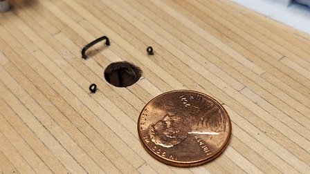
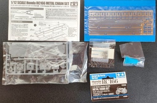
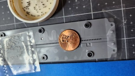
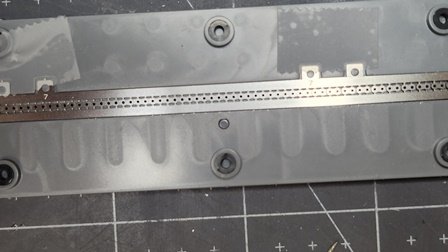
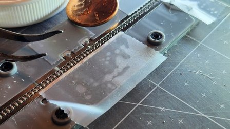
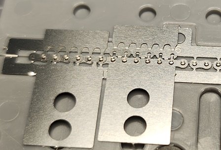
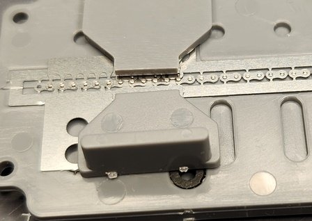
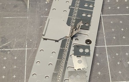
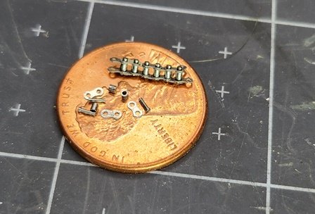
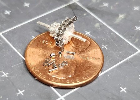
Here's the kit and instructions. It's a Tamiya Metal Chain Kit. The particular kit I bought is for a Honda RC166. Part #12633. The kit contains photo etched side plates and clips. There is a packet of plastic sprues with the assembly jig and tools. There are packets with incredibly tiny rollers and pins. Also a plastic tube of locktite like material. The kit makes a working roller chain! That is of little relevance for my model which will be static - but it's really cool. The instructions have good illustrations and somewhat limited text steps in four languages. The tube of locktite turned out to be almost dried out. There are some plastic gears for the motorcycle. One of which is the right size to use as a replacement for one of the Britannia metal gears. Everything is high quality and very detailed. The first step is to assemble the jig and insert the rollers into it. These parts are really tiny! How do they get them so precise? The rollers are about the size of Lincolns nose. If you drop one of these it's impossible to find again. Fortunately they provide plenty of extras. I had about 15 left when I had filled all the roller holes. The side plates are attached to strips of metal and there are keying posts in the jig. Everything is numbered very nicely. Now the pins are dropped into the holes in the chain plates. These are harder than the rollers; mostly because you have to poke them into a smaller hole. They're also harder to grasp as they have a "head" on them. I used some tape to keep the springy metal down. It's really easy to nudge this and pop a bunch of pins up. A supplied cover is placed over this assembly to hold the pins in place. The jig is inverted and the bottom cover pulled off. This exposes the rollers on the other side. Another side plate assembly is inserted and the clips installed. This is done in groups of three. There is a tool set provided to snap the clips in place while holding the assembly tight. There is some considerable force required. My fingers were a little sore when I finished. The excess material is then snapped off. The sprues are then removed. First the clip side. Then the jig is inverted and pin side sprues removed. The chain looks very nice but is quite delicate. It's important to test each clip and tighten them as needed. I missed a couple and had my chain come apart. The kit designers thought of this as well. There are tools to refasten links. These parts are amazing. They make a pretty good fit to the Britannia metal gears.
-
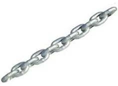
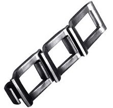
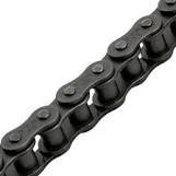
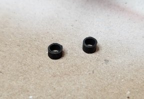
Mentioning the machinery got me thinking about the chain types needed for the model. Bluenose has pretty ordinary anchor chain. That seems to be available from many sources in a wide range of sizes. The machinery uses a different type of chain. I could not find it on any of the usual ship modeling sites or on other hobby sites. There are three basic types of chain and each has some variations. Anchor chain comes in standard links and for larger ships the chain has cross link reinforcements. The three types are shown below. The first is your typical anchor chain. Next is what the bluenose machinery of the 1920s would have used. It's called Flat Detachable Link chain. The third is more modern(and efficient) roller chain. In the 1920s roller chain would have been expensive to manufacture and for farm and ship machinery efficiency would not have been a consideration. The flat chain would have been easy to punch from sheet steel with little finishing required. In photos of the machinery you can see the chain is indeed Flat with the square holes. There is one link that has a through bolt and roller. That's no doubt the "Master Link" used to couple the chain ends together. In researching other build logs and web sites I could not find the flat chain in scale. I have seen jewelry that uses a similar style, but it's usually gold and expensive. It would also be hard to find at the right scale. Most builders appear to adapt anchor chain which really doesn't sit right on the gears because the links alternate direction. I did find a builder who used scale motorcycle chain(sorry, can't remember who). This is actually roller chain but it's close in appearance to flat chain at the small size needed. 1/12 scale roller chain appears about right. Tamiya makes a kit to create 1/12 scale motorcycle chain that comes with jigs to assemble it. I bought a couple and will see how it works out.
-
Hi Gregg, Thanks for your comments. I see you're starting your decking. I found the decking the most satisfying operation so far. The machinery was also fun. I have two more deck buildings to go before I can install that. John
-
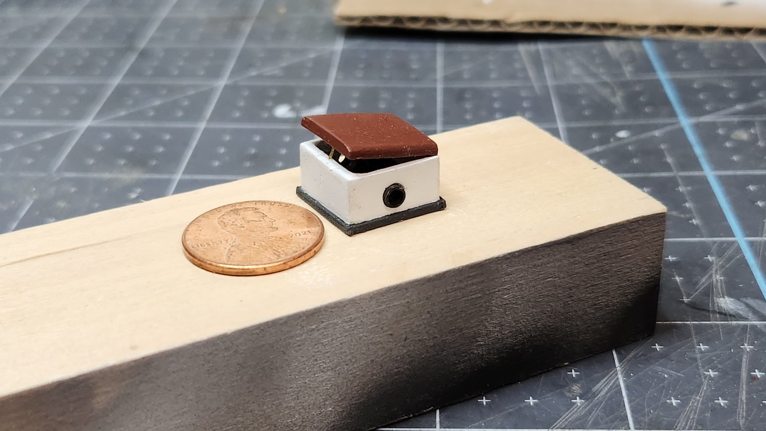
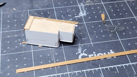
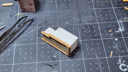
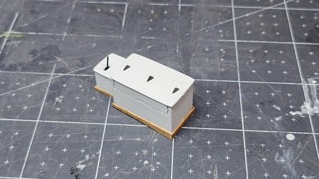
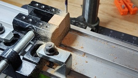
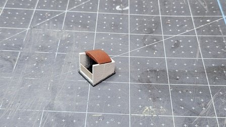
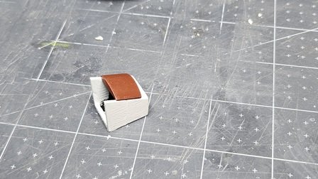
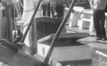
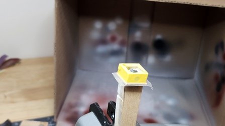
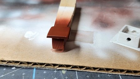
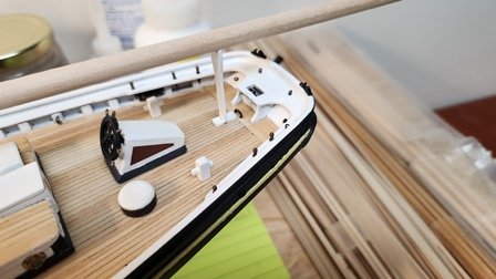
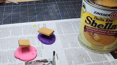
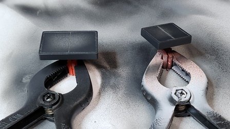
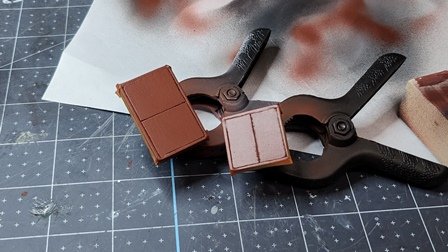
The skylight shown on the plans is, again, much different than the one in photos of the ship. I like the one in the photos. The one on the plans would more likely be found on a passenger ship than a working boat. Much to fancy. The one in the photos is easier to make. It also has the has a hinged lid. That will add more interesting detail to the model. Here's the one in the photo; It's not clear what type of air vent is on the side. Could be a shutter or angled vents. Or even a round hole that simply doesn't show well in the photo. I decided to go with a round port as shown on the plans. Inconsistent I know. Builders choice! A solid block was again used. Two pieces of scrap were glued together to get the height. Then the block was cut and sanded to size. Because there will be an open top, it was necessary to cut out the interior partly as it will show. The drill press with a milling tool was used to hollow out the block. I didn't cut all the way through to retain strength. The box was then shellacked, sanded and primed. Because all four sides and the top are being painted, holding the piece while airbrushing was a problem. The pieces are so small and light they blow away when hit with the airbrush. This was solved by using double sided tape to hold the work piece on some scrap that I could then hold with my hand while painting. This had the further advantage that I could turn it to the optimum angle for painting. The inside bottom was painted flat black. Then masked while the white was sprayed. The top was made from scrap of the appropriate thickness. In the photo the top is a different color than the bottom. Given the trim color seems to be burnt umber, I used that for the top. Makes a nice contrast. While the paint dried I cut some small pieces of 3mm brass tubing for the airports and blackened it. Next the coaming was glued to the bottom. I didn't bother with mitering as that detail would not be visible. I glued the coaming strip to opposite sides and trimed. then glued coaming to the remaining sides. After the glue dried it was masked, sanded and the dark gray color applied. Again the tape on a stick method was used for paint application. A small brass wire was used for the prop holding the top open. The top was epoxied on for strength. The top is open just enough you can see the light from the airport. Here's the result...

-
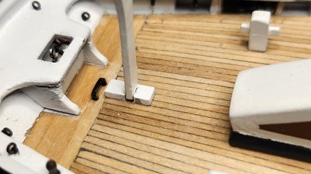
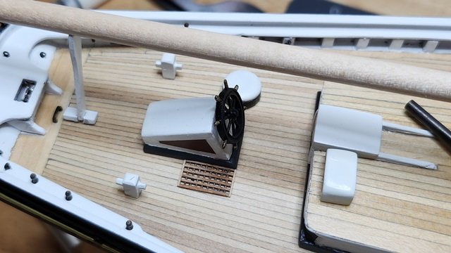
Thanks for the feedback! Maybe the thinking was "outside the box", but the patience not so much. As my lost fingerprint testifies. To answer your questions; The steersman would have been facing forward both to see where the ship was headed and to view the compass which is on the roof of the deckhouse. Also there is usually a telltale at the top of the mainmast for wind speed and direction. If he were to stand forward of the wheelbox it would be awkward to reach behind to grasp the wheel. The only convenient spot to work the wheel and see the compass would be behind the wheel or to the side of it. Other photos where the deck around the wheelbox is visible do not have a grate. There would have been no point in other places anyway. These ships were about practicality first and foremost. Any decoration would be secondary. Remember, Bluenose was designed as a work boat. An interesting observation is how the steering mechanism worked. If you look at the steering mechanism on sheet 4 of the Model Shipways plans you will see that it's a double screw drive with the leverage on the wheel side. A screw drive prevents rudder feedback from moving the wheel, while the wheel can easily move the rudder. This means that in open water the steersman could leave his post and help with other operations. Barring changes in wind or currents the ship would stay on course. It also means operating the wheel does not require great strength. RetiredGuy did a wonderful job of producing a working scale steering mechanism. Check out his Bluenose. John
-
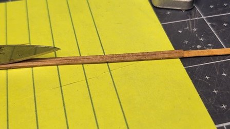
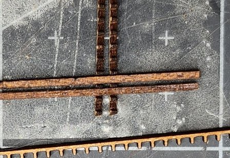
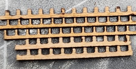
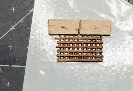
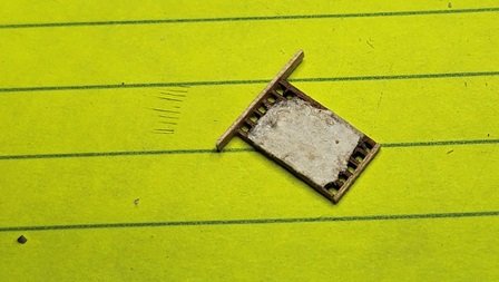
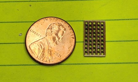
There is a grate by the ships wheel for the steersman. I suppose this is to keep their feet dry when water is sloshing across the deck. The one in photos has what looks like 2 or 3 inch square holes. The plans do not show much detail. Rather than try to create such small square holes I opted to buy some grate material. The smallest I could find was 1mm. This is bigger than scale but at least the holes will be square. My first thought was to have the notches interlock as the prototype probably did. This did not give a good appearance and would be too thick. A better effect is made by placing them side by side. The strips are laser cut and there is an angle to the shape so that one side of the strip is thinner than the other. That can be seen in the photo above. The thicker side was chosen as the detail will disappear at viewing distance with the thin side. These were tricky to glue together. They are so light and tiny they tend to stick to anything that touches them. I experimented with a number methods. I got the best result by using double-sided tape to hold them in place while gluing. Cyno was used as I could use a pin to drop tiny amounts of glue on the joints. As usual it was pretty messy. The problem is to get it all in place before the cyno set. Unfortunately, after all pieces were in place I touched it before the cyno had quite set. I then had a perfectly nice grate attached to the end of my index finger. The physical stress of getting it off my finger would be too much for this fragile assembly. I glued a paper to the bottom of the grate with PVA. After that set, I went to work with alcohol and a scalpel. The paper gave it enough strength to get it off my finger with no damage to the grate and little to my finger. I then glued the end pieces on and trimmed them to size. The next step was to gently scrape the paper off and clean out the holes. The grate looks nice, though the holes are a little big.
-
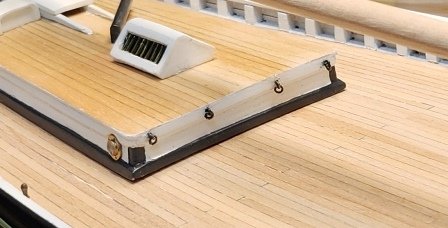
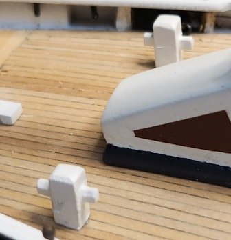
Added the mooring chocks and anchor pads. Airbrushed the mooring chocks flat black and the anchor pads the dark grey coaming trim color. Scraped the paint from a small area under the pads and chocks to increase adhesion. As these small exposed pieces tend to get knocked off epoxy was used for strength.
-
Thanks Gregg! I appreciate the encouragement. There are times when I think of the next process and feel overwhelmed. One step at a time and it progresses. My goal this winter is the deck furniture. And maybe getting the masts dressed. I checked out your Ballahoo today. Very nice! A great looking model. I see you are planning to add an America to your fleet. That one's waiting in my shipyard as well. I have the Constructo kit. It's very old but everything seems intact in the original packaging. There was a paint set with it but it's so old the paint may not be any good. At the pace Bluenose is going it will be a year or two before construction starts. John
-
For the Galley stack I like the "Dreadnought head" supplied with the kit. The Britannia metal part was not a bad casting, but there were no holes in the pipes. My first thought was to use a milling tool to cut the holes. This did not work out well. It was difficult to clamp the part at the correct angle. More importantly, the Britannia metal did not mill well. It tends to smear and the tool was prone to wander off axis when I started getting deeper into the metal. I decided to cut the pipes off and epoxy brass tubing onto the part. To get the correct fit the pipe molding was first sawed in half with a jewelers saw. A round file was used to cut the rest of the way and create a proper shape to hold the tubing. The brass tubing was epoxied in place. Then repeat for the other side. After some cleaning and polishing the part was primed and painted flat black. A small base was constructed with a hole drilled in the center as show on the plan. Looked pretty good in the end. With real holes!
-
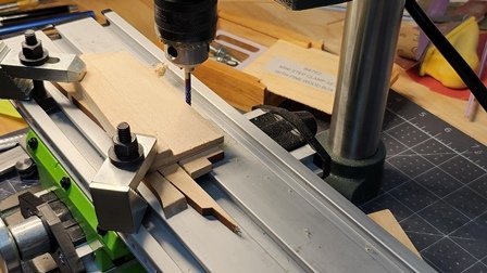
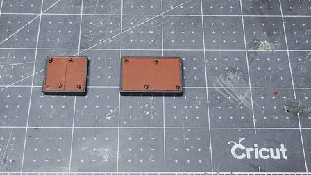
To make the hatches, I again used solid blocks. Double sided tape was used to fasten two pieces of scrap together. The bottom block protects the X-Y table from damage when cutting through the finish piece. A milling tool was used to cut out shapes to size. A slight over size was left to allow for sanding. The corners of the blocks were rounded as shown on the plans using sand paper. The blocks were sanded smooth, coated with shellac and sanded again to get a nice finish. The airbrush was used to put on a primer coat. The backside of an Xacto knife was used to score the blocks, simulating coaming and covers. In retrospect this didn't work well for cross-grain scores. It would have been better to use the knife side first to cut the grain, then score the block. The results were pretty good and acceptable at viewing distance. Next dark grey was sprayed on the coamings. After the paint thoroughly dried Tamiya masking tape was used to protect the coaming and the hatch cover color was sprayed. After that, holes were drilled for the tie-down rings as shown on the plans. The result looks good. Once again the supplied plans do not agree with photos. The actual hatch looked quite different and there are no tie-down rings. However, the hatches on the plans are more visually interesting. Of course the ship may have been originally built like the plans and later additions and modifications to the hatches made.
-
Glad I can help. Lots of great builds to learn from. I've found many tips that way when I'm stuck about a procedure. MSW is a great resource. Feel free to ask questions too.
-
Thanks!
-
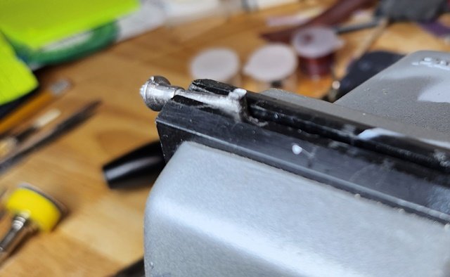
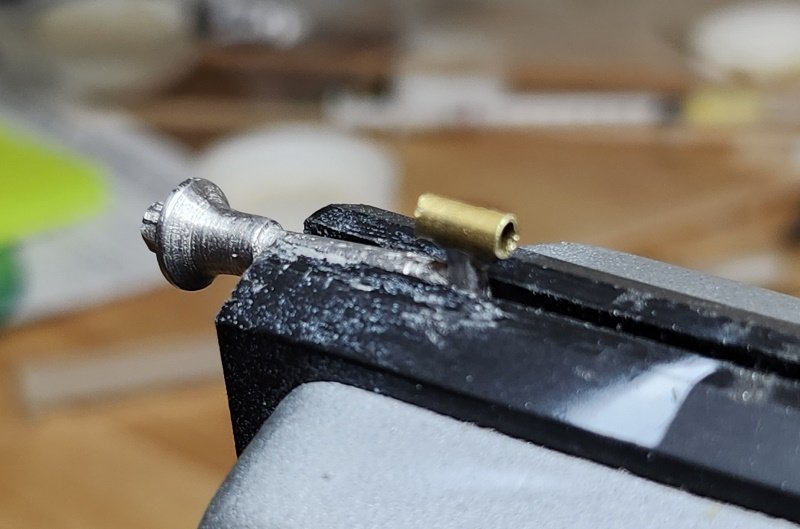
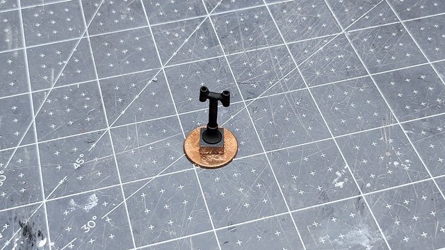
The mainsheet horse was made from flat brass strip and blackened. Epoxy was used to cement it in place as there will be some strain on it. Tie down loops were installed on the cabin. The fife rail and forward boom buffer were installed. The britania metal bilge pumps were so-so. A lot of filing, sanding and paint took them to "just" acceptable. They are at least consistent with the level of detail of the rest of the model. I decided to make and attach the pump handles because the pumps just look like odd black lumps without the handles. I realize that on the actual ship these would have been stowed unless needed. It adds an interesting detail to the model. The hinge ears for the handles were barely there and mostly solid. A jewelers saw was used to open them up. I didn't have thin enough material for the handles. Two strips of walnut veneer were glued together to get the correct thickness and then split and shaped to make the handles. After painting with flat sealer the handles were epoxied to to the pumps which were painted flat black to match the other ironwork. The supplied metal pieces have a small button on the bottom. An appropriate hole was drilled in the deck and PVA was used to cement them in place. They actually turned out pretty nice. Of course I'll probably break them a couple times while rigging😄. The quarter bits will have a some strain on them. They were mounted by drilling a hole in the bottom and cementing a short length of pin in them. This was glued into matching holes in the deck.