HOLIDAY DONATION DRIVE - SUPPORT MSW - DO YOUR PART TO KEEP THIS GREAT FORUM GOING!
×


JohnU
-
Posts
170 -
Joined
-
Last visited
Content Type
Profiles
Forums
Gallery
Events
Everything posted by JohnU
-
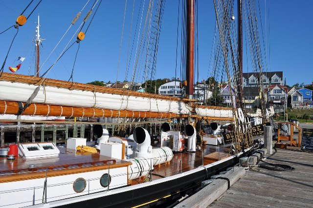
 Time to assemble the parts! Portholes went in, companionway cover, compass cover, skylight and pipe. I then did a quick spray of the metal parts with clear, flat paint to protect them and dull the finish a bit. This turned out to be a problem for the blackened pipe. The port holes were OK. The pipe had some sort of reaction between the blackening (Brass Black) and the finish. Small problem though. Just had to sand the pipe and re-blacken. I used cyno for fastening the portholes and insert a pin in the pipe which was PVA'd into a locating hole drilled in the decking. The companionway cover, skylight and compass cover were simply glued on with PVA. The ships wheel was pressed into it's hole on the steering gear cover. The porthole windows(which came with the portholes) were pressed into place. Parts are ready for mounting on the model! I'm not really pleased with the way the cabin turned out. As I mentioned earlier I built it according to the supplied plans and didn't consult the historical photos before I built it. The original "as built" cabin is different in height and shape and trim. In fact, it would have been simpler to build. I'll see how this one looks on the model and think about it for awhile.
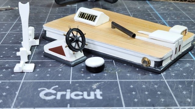
-
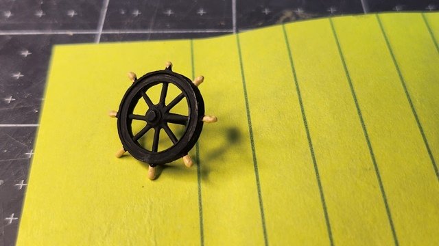
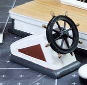
The ships wheel supplied in Britania metal was, surprisingly, a pretty good casting. This was an older kit. I understand from blogs the newer ones have worse metal parts. There was just one handle that was bit small. I'll position that at the bottom where it's not so noticeable. There was the usual fileing to remove mold seams but it cleaned up nicely. Even the shaft was not bad. I then used a light buff paint for the handles. These were a little bright so I went over them with some Tamaiya Smoke paint that is a very light grey and transparent. This dulled them just right and shifted the tint to more of an aged wood appearance. The photo below is before the Smoke was applied. Flat black matches the rest of the iron work on Bluenose. Next was the accent paint on the steering gear box. This was an exercise in masking. I've been having some trouble getting the tape to adhere properly. I've had to do quite a bit of touch up from paint that leaks under the tape. Usually I have good results from taping. Perhaps my tape is getting old. In the end it turned out nice.
-
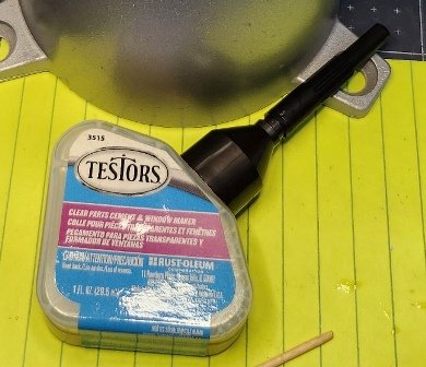
While at the hobby shop getting my Tamiya White Flat paint I asked the owner about slide cover glass for windows thinking to to make an attempt at glazing my windows. He suggested a Testors product "Canopy cement and window maker". The claim was you can make windows with it. This is one of the reasons I like to support my local hobby shop when I can. Back at home I did some research on the web for instructions or tutorials. Testors is not the only product of this type. They are used extensively by airplane and HO railroad modelers. Not so much in the ship modeling world. The way it works, you put a glob on the end of a small stick and slowly run it around the edges of the window frame. As the glue builds up on the frame the surface tension eventually starts carrying a film across the window. It's cloudy when it goes on but dries perfectly clear. Because it works with surface tension the panes are slightly curved. For small windows, (or lights in the case of Bluenose), it works well. It would not be suitable for large glass windows or windows you want to see through. I also used it as cover for the compass hole. Anyway it worked pretty well to fill the mullions of the skylight.
-
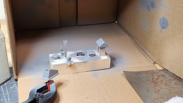
I sealed everything with shellac as many recommend. Then sanded and filled as needed. This does a great job of getting rid of the fuzzies. Then it's time to get the painting tools set up. I find that with an airbrush and using acrylic paints there is little over spray or odor. I used a cardboard box as a makeshift spray booth. I just throw it out and get another when it gets too gunky. There's no fan or filter but the airbrush uses minimal paint and little over spray. Primer went pretty well. It only took a couple rounds of filling-sanding-paint. However, I mixed the last of my flat white incorrectly and will have to visit the hobby shop before continuing. I need some other things anyway and I like to browse there.
-
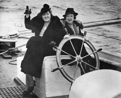
Hi Gregg, What a great idea! More summer type clothing though. There are places that sell miniature figures. I'll have to see if I can find some in the correct scale. It's hard to find ones of women though. Could probably transgender some male figures.
-
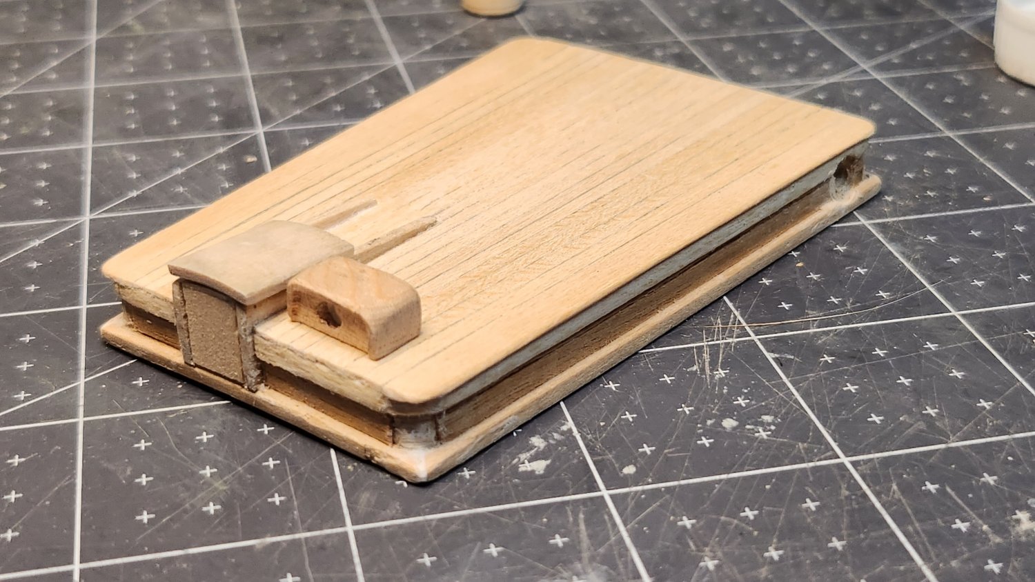
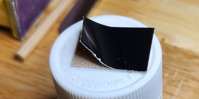
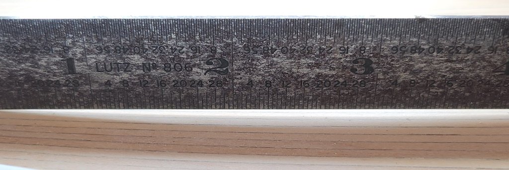
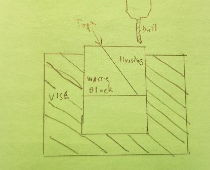
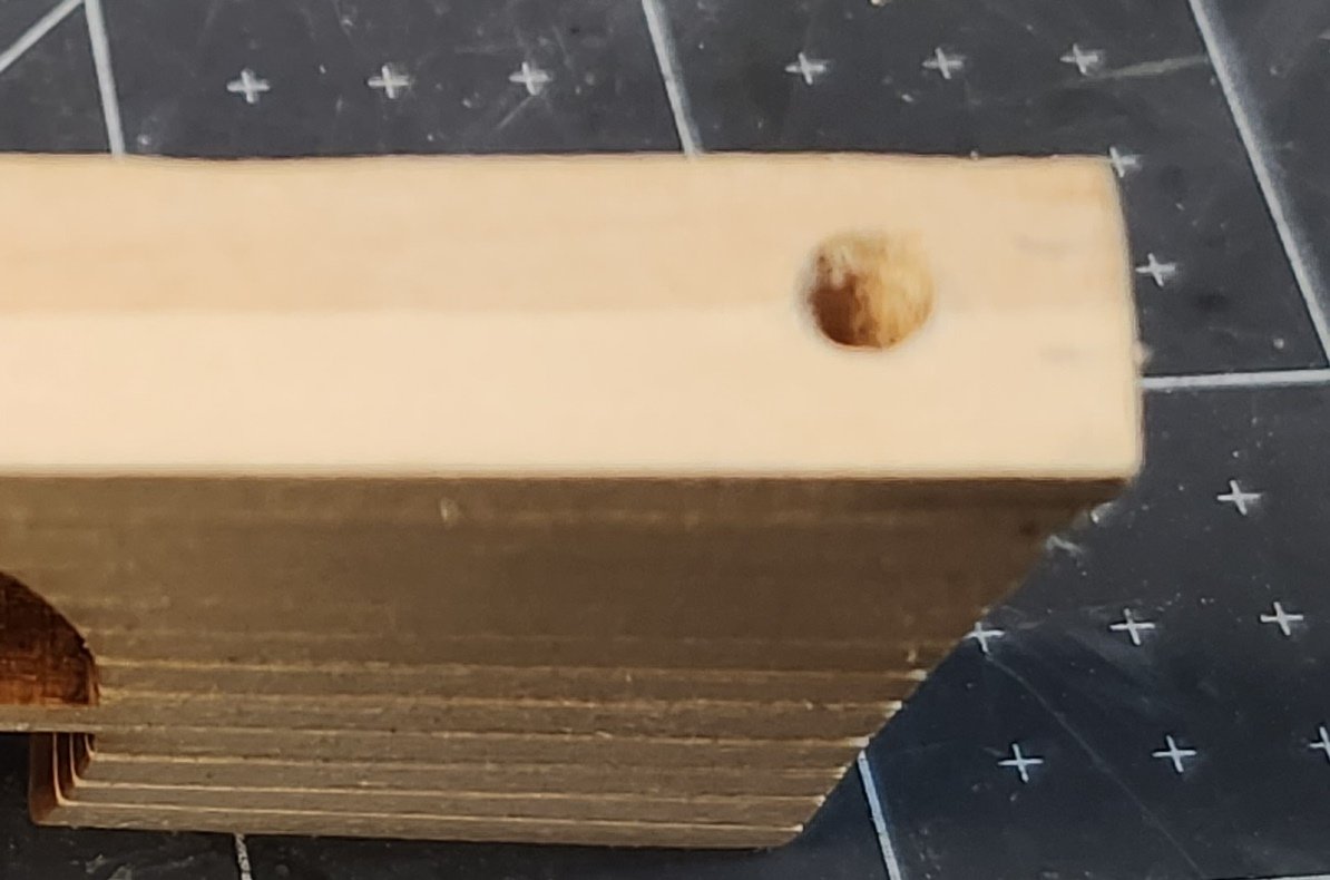
In the end, I decided to do simple bars for the skylight. After assembly I painted the interior flat black. To conceal the decking under the skylight I found a piece of black cardboard which, of course would be too thick under the skylight. To fix this I simply peeled the thin paper layer from the cardboard and glued that to the bottom of the skylight. Next the windows were masked preparatory to airbrushing. While trial fitting the cabin I noticed it would not lie flat along the axis of the ship when put in it's normal position. Testing with a ruler showed a slight dip in the decking at about the middle of the cabin. To fix this I pried the coaming from the cabin sides and installed a wider coaming in it's place. I then sanded a curve in the bottom of the coaming to get a good fit in the bowed area. It's now time to tackle the steering gear housing. I approached this with some trepidation as there are odd angles involved. The plans show a complicated cabin top with coving and and a flat roof. Given my experience with the cabin, I first checked photos of the prototype. I found two from different eras. They were the same except for the paint scheme. The housing in the plans was quite different. The prototype had a companionway like cover. That actually makes a lot of sense as it would be necessary to access the steering gear frequently for service. There's also a dark colored box behind housing in the later photo that continues the slope of the top. That's not on the plans at all. I'm guessing it was some kind of toolbox. The earlier photo doesn't have the box. I believe I will go with the earlier photo for the construction and the later photo for the paint. The color will add interesting detail to the model After debating how to construct the steering box, I decided it would be best to follow the same procedure as the cabin. I started with a piece of 3/4 inch plywood veneered on three sides. This was cut to height and squared off. I did test cuts on scrap to find the proper angle(F.Y.I 25 degrees) and cut the slope into the bottom of the housing. The housing is basically a solid rectangle with the bottom cut at an angle. To make the cutout for the wheel I simply cut the veneer appropriately. To create the hole for the wheel shaft I used the waste block from the angle cut secured with double-sided tape. this allows the block to be clamped square. That produced a nice square hole for the wheel shaft. The top was made from a plank of the correct thickness and sanded to the required shape. The deck fittings made so far were placed on the deck for a test fitting prior to filling, sealing, finish sanding and paint.
-
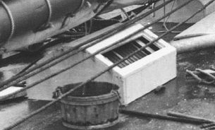
I managed to find a good image of the cabin of Bluenose II. Notice the deck arrangements are quite different from the original. It was built as a passenger ship rather than a working fishing boat. There are definitely bars on the Bluenose II. However the skylight is quite different compared to the one on the original. There were many other significant deck furniture changes and interior changes. Both are different than the plans in the Model Shipways kit. On page 20 of the Model Shipways manual under "Deck Structures" it says "Cut mullions and stringers from brass wire; or, fake it and paint on the dividing bars". But then we know how reliable and complete the manual is🙂.
-
I'd like to see that photo. This thing with the bars has been a puzzle since I started the project. Of course there were departures from the original in Bluenose II. But I don't see why they would have changed the skylight. Except perhaps, it's position. Maybe I can find some relevant photos on the internet.
-
The cabin parts have been given a coat of shellac preparatory to final sanding and painting. While waiting for that to dry I constructed the boom crutch block and quarter bits. The quarter bits turned out to be easier than expected. I cut the post to height and drilled a hole to insert a toothpick. Or rather, I milled a hole. I've discovered that ordinary twist drills tend to tear or split the soft wood. A milling tool makes a much cleaner hole and doesn't stress the wood. A toothpick is, of course to large for the crosspiece. Once it's inserted it can be filed to the correct shape and size.
-
The general approach seems to be a glass slide over or under the bars. This doesn't quite make sense in terms of the prototype and photos. I'm inclined to think there are actually not bars, but metal webbing holding multiple panes. As in a stained glass window. This might be better approximated by using a glass slide and painting the lines on it's surface. This idea appears consistent with the best photo of the cabin. Although there seems to be some sort of box over the skylight that's not on the plans. Some sort of afterthought perhaps.
-
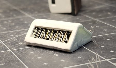
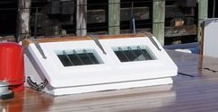
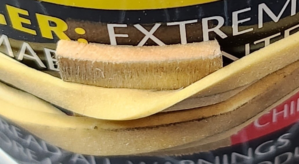
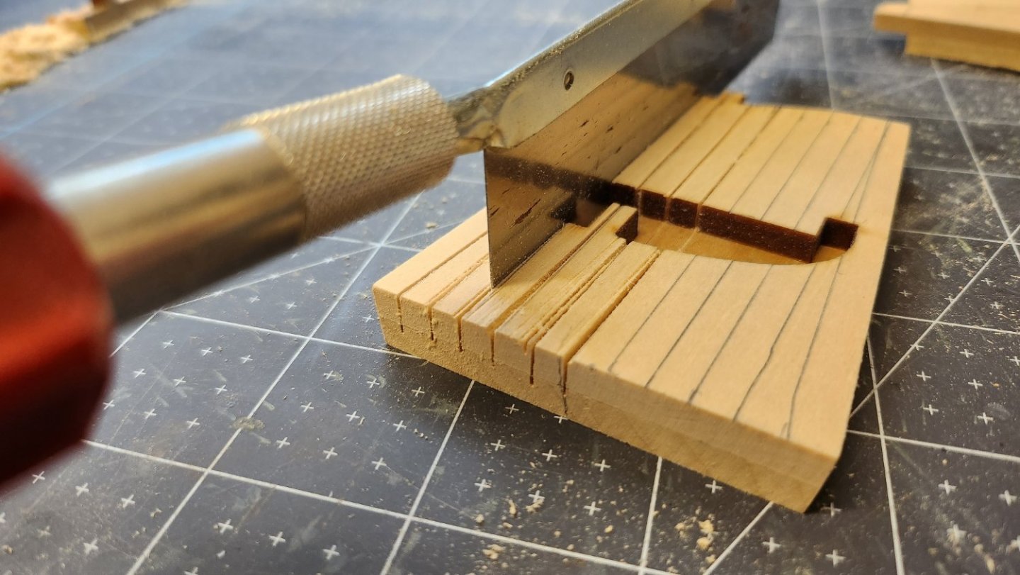
Worked on the skylight and stove pipe today. The skylight is a finicky delicate piece. It took some experimentation to come up with a method. Using a solid block would not work as space is needed behind the windows to look right and accommodate the bars. I came up with this solution. Note the t-bar across the top. That's to get the height correct for the window thickness. To ensure matching openings I used double sided tape to hold the windows down and laid them out together. Fastening the bars to the window is problematic. I didn't want to use epoxy because the heat generated in cutting the wire would degrade the epoxy. There's not a lot of room under the window. The pipe was cut from brass tubing. Note the wall thickness of the tubing was larger than scale so I counter drilled the end to approximate the scale wall thickness. The two pieces were silver soldered together using a ceramic pin jig. The jig worked much better than trying to use clamps. Almost all the pieces are done. Just have to get the windows figured out.
-
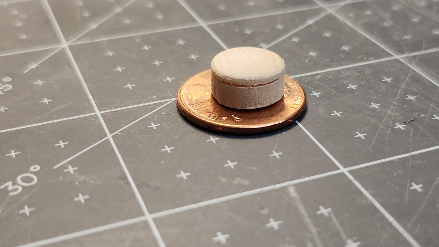
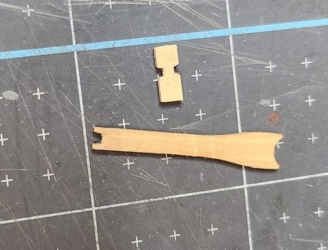
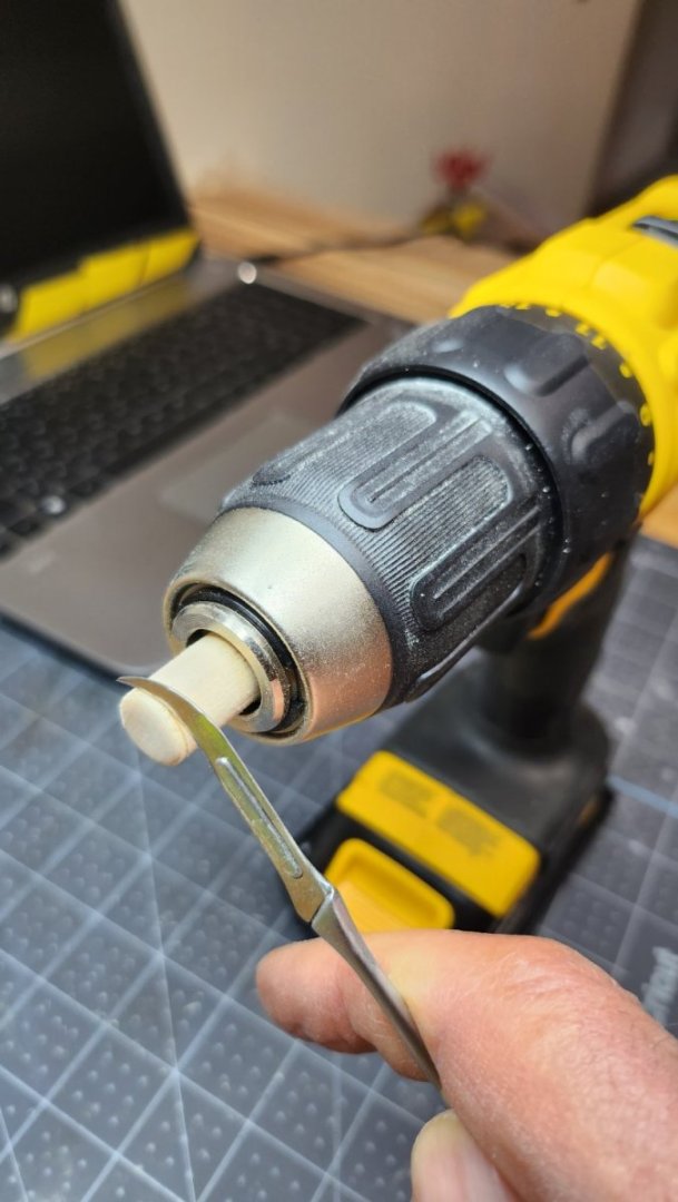
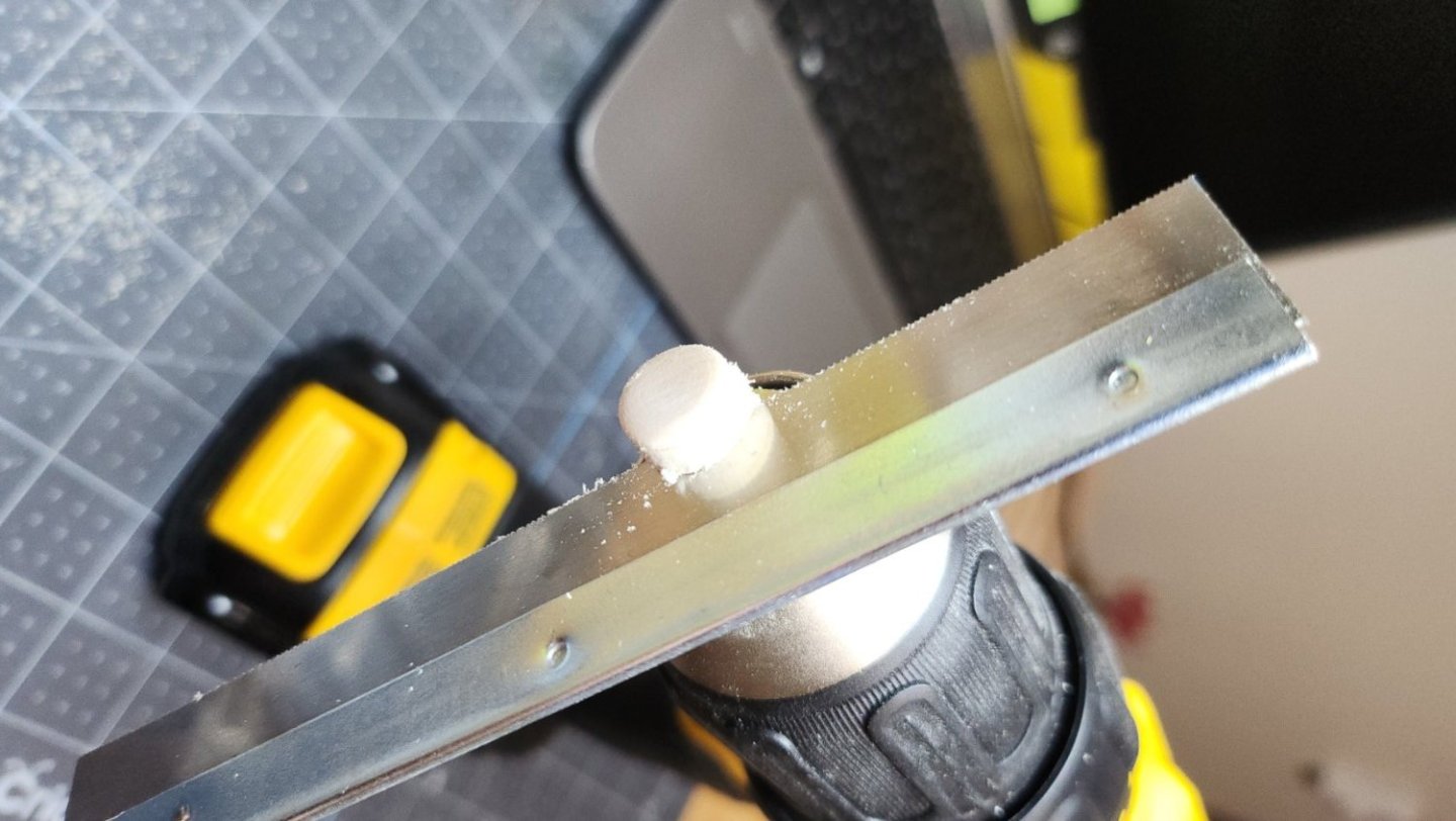
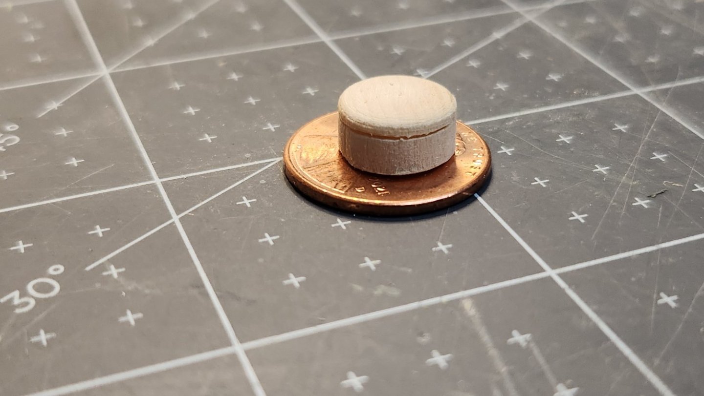
For a change of pace to something simple, I did the mysterious "unknown object". For lack of a lath I chucked a piece of dowel in my drill. This works OK on small, uncomplicated pieces but is awkward as I have to hold the drill trigger and my cutting tool at the same time. First the end was rounded with a sanding block. A hooked scalpel cut a grove to represent the lid. I finished by cutting the piece off with a fine tooth saw. This looks the best so far! It's always fascinating to me how tiny these objects are and how much detail can be put into them. The compass housing is 6mm x 12mm x 8mm with a 1mm lip on each side. The "unknown object" is made from a 7/16" dowel. They are both smaller than a penny!
-
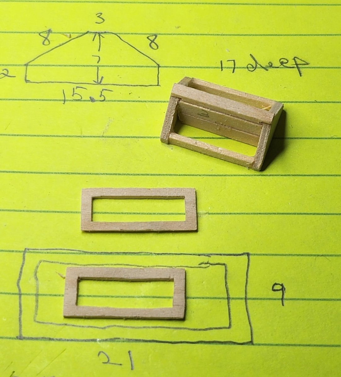
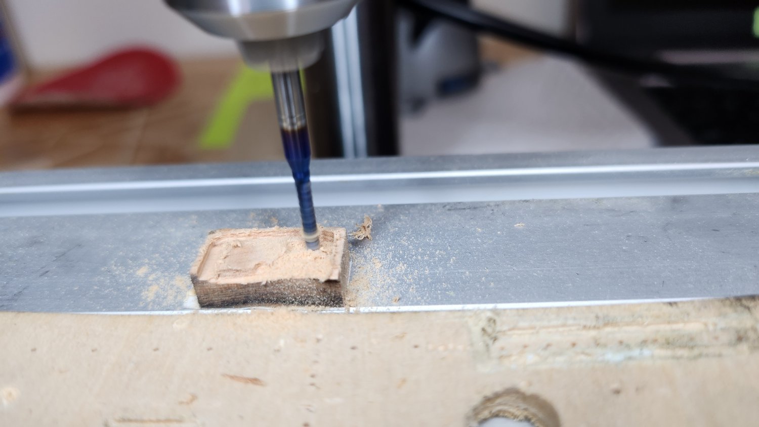
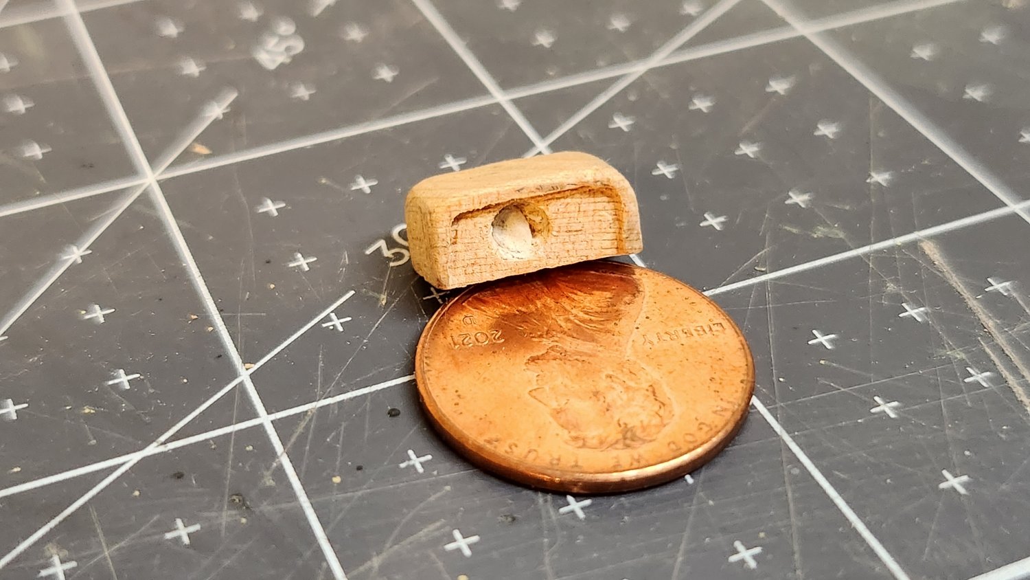
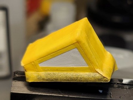
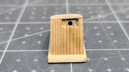
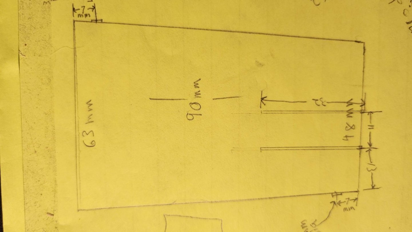
To make the hatch cover I used the same method that was used to bend the cabin. Heat, steam and a mandrel. Though the hatch required a smaller radius. The compass housing required some experimentation. My initial thought was to use three pieces. A cover, front and back. I had difficulty bending the radius in such a wide board using my usual method. In the end I decided to work with a solid piece. I cut a block the required dimensions, then sanded the corners off one side to get the required radius. To cut the front and rear lips I used a mill and X/Y table. This is my practice piece. Here's the carved compass housing;


-
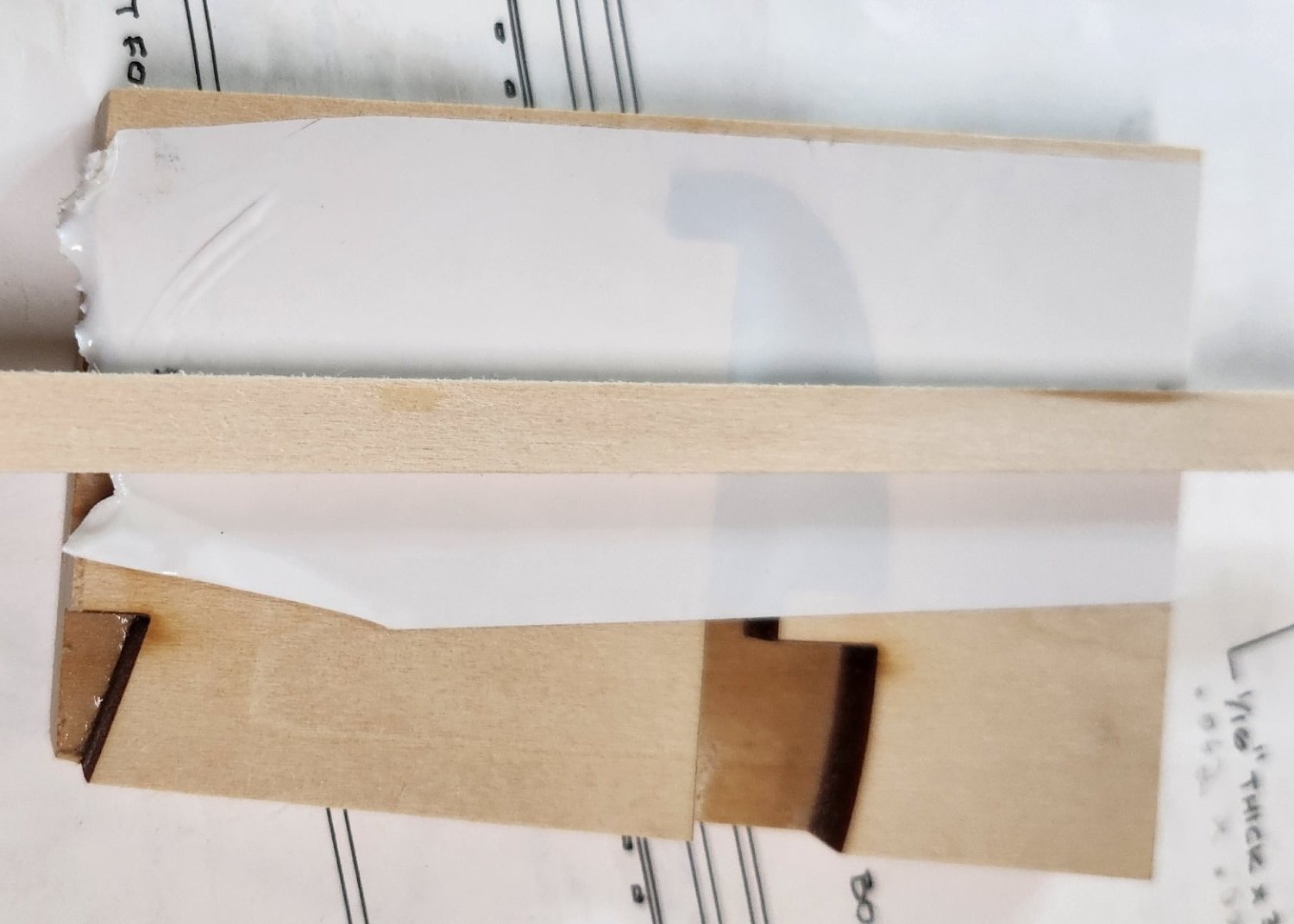
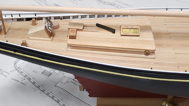
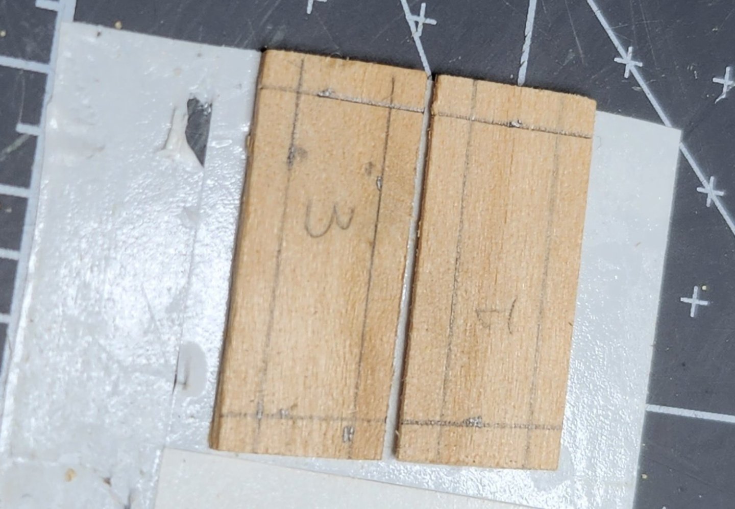
Here's a picture of current progress. At this point it still needs a lot of sanding and filling before the finish is applied. Also the doors need more work.The base trim is sanded to an approximation. Corners are filled. The siding ends at the corners with some reveal of the edges as show in the plans. I may yet sand that flush. The top trim piece was bent from one long strip using the steam iron method. The roof deck boards are tapered in the same fashion as the rear main deck. This required some calculation. The distance between the side boards at the forward end was 51.5mm and I'm using 2.5mm boards so 51.5/2.5=20.6 boards and the stern end measured 38.5mm. Thus 38.5/20.6 boards=1.87mm for the tapered end. In practice getting that precise dimension was impractical. I ended up with a gap slightly wider than a board width on each side. I simply took a wider board and cut it to fit. My porthole flanges were a bit wider than the gap between the trim pieces. I used a Dremel tool to carefully carve the needed radius into the trim.

-
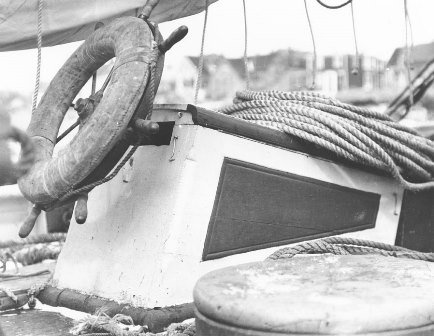
I have a quandary. I've pretty well finished the main cabin and decided to take a look at the photos of the ship. I had constructed the cabin as shown in the plans using the dimensions drawn. When I look at the photos there are significant differences; The siding is vertical - the plan shows it as horizontal The base and top trim are very thin. More like you find in a house. The plan shows it as having significant thickness. The lip of the roof extends beyond the trim. The plan shows it as flush. The portholes are significantly smaller than shown in the plan. The skylight appears to have a much different window arrangement. It actually looks like a box was constructed over the original skylight. The horizontal pipe is facing rearward in the photo, the plan shows it facing forward. The biggest difference; the sides are orthogonal to the deck, the plan shows a significant inward slope to the sides. Now I have to decide whether to start over or go with what the plans show. While I prefer to stick with the prototype as much as possible, I do like the version shown on the plans. The thicker trim provides nice detail and I've already cut the lip from the roof on the ends. My portholes have a flange that is considerably larger than the flange in the photo(the actual window is the plan size.) and I really like the look of those portholes. I was going to keep the roof decking the same as the main deck anyway. It's a dark color in the photo. Although a light grey like holystoning provides would be nice - if I an figure out an appropriate wash.
-
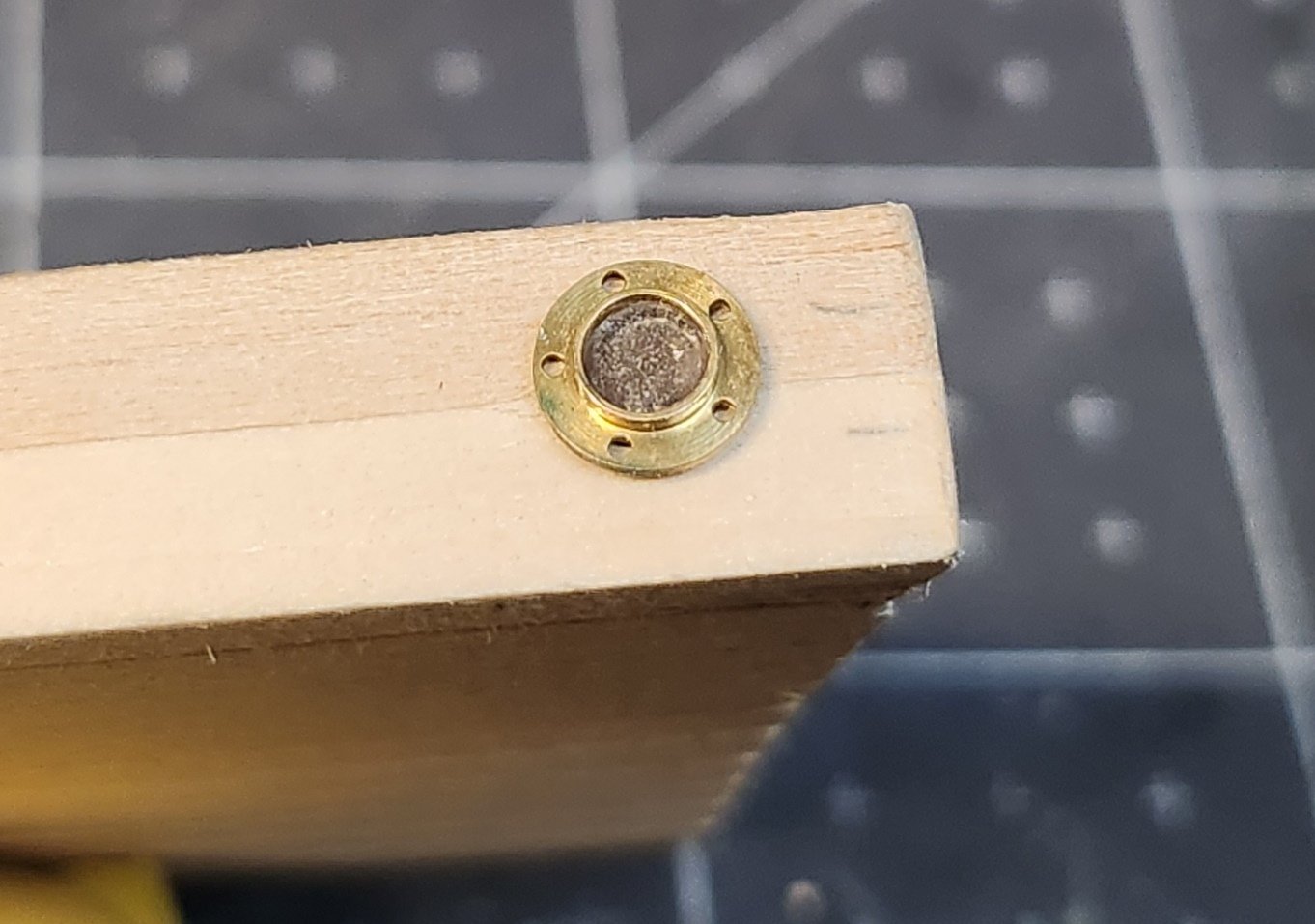
I had ordered some really nice scale portholes and couldn't wait to try them. I drilled the proper hole and inserted one just to see how it looked. Of course it will have to come out to allow the rest of the finishing process. These are the last thing to go in. Very nice effect!
-
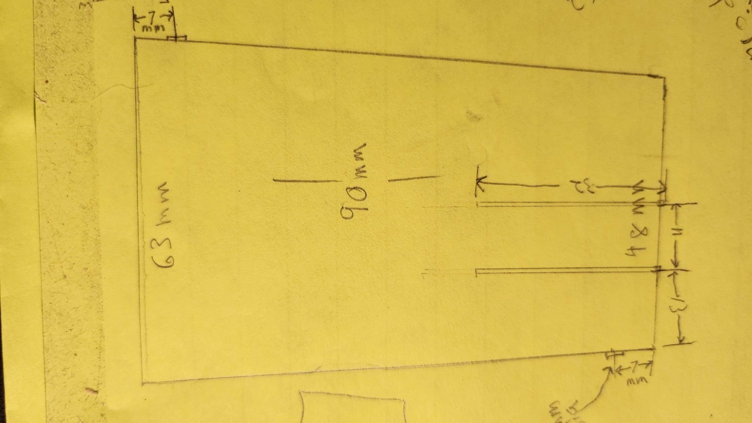
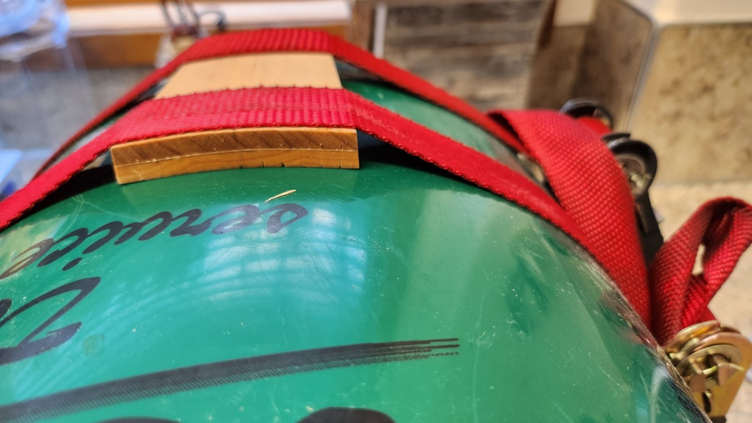
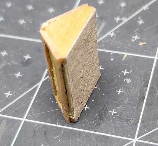
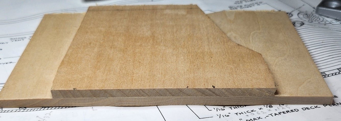
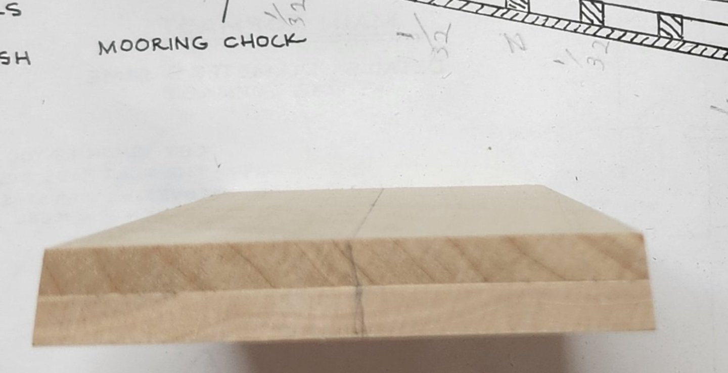
I have started the deck furniture. This was a dreaded part of the job. So many structures with tiny, finicky details. It's really not any worse than any other part of the job. I'm just procrastinating. I decided to start with the most complicated structure. The deck cabin. I've also switched to using metric measurements. So much easier to scale. The problem of how to build the basic structure was the first step. Rather than try to build tiny framing, I used a couple pieces of scrap of appropriate thickness to make a solid core. This greatly speeds the construction and is very a very sturdy base to work from. The first step is to laminate the two pieces of scrap: The dimensions were then scaled from the drawing and laid out on the block of scrap. Allowance was made for the siding thickness: The basic shape was cut with a saw. The sides slope inward at a 6 degree angle. I calculated the size shim I would need under the block and used a bench sander to create the taper. The shim was attached with double sided tape. Note; it needs to be parallel to the tapered sides - not square with the ends: This is a bottom view. The voids are due to one piece of scrap having cutouts. These will be filled with wood filler. Turned out very nice:Of course this is flat block Because the deck has a slight crown, it needs bending. It's a laminate and is very resistant to bending. I cut feather slots in the bottom sufficient to allow the right curvature in the bottom layer of the block. Now there is only a single layer to bend:The block was soaked for a few minutes in water and a hot iron applied. This was repeated until the wood fibers lost their strength. Next the block was strapped tightly to a large bucket to get a gentle radius and allowed to dry overnight:


-
I see my last entry was June 2021. It's been a momentous year and a half! Covid lock down, election disputes, Ukraine war, weather disasters, mass shootings, so many events. I've finally started up on my Bluenose build again. As my last post stated I had a custom kitchen to plan and install for my wife. Due to Covid the cabinets took much longer to have built and installed. The countertops were delayed, parts were hard to get. It took a year just to get everything installed. I also decided to rip up all my floors and redo them. Then the old cabinets were installed in the garage. All in all it took a long time. But enough of that! Time to post Bluenose progress...
-
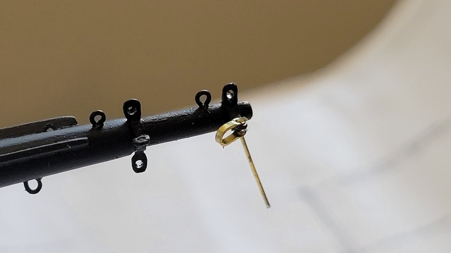
I gave up trying to find suitable shackles. My first attempt at making a tiny shackle. I'm not quite satisfied with it. The ends don't fit through my turnbuckles. Have to think about that. This is about as small as my current level of skill can do. In any case, it's time to put Bluenose in drydock. This summer, and probably fall, is kitchen remodel time. It will be a while before I make another post. We had put the kitchen off because of the pandemic as we didn't want to be out mixing with people more than we could help. Thanks for all the great comments and I will continue to monitor the build logs. John
-
Hi Per, That's very interesting. My experience was just the opposite. It took a little over two weeks to get the parts from Cornwall and Model expo has always been about a week. Perhaps it's something to do with the pandemic. Even more problematic is I ordered some parts from Cast Your Anchor in Toronto which took three weeks. I tracked it and most of that time was in customs. That may be why my Cornwall order took so long. I must have been looking at the wrong page. All the prices were in British Pounds when I ordered. Perhaps there's a different way to connect to the site that tells them the web browser is from U.S. What URL do you use when you shop there? John
-
Great kit and parts source
JohnU replied to JohnU's topic in REVIEWS: Model Shipwrighting Tools, Parts and fittings
Whoa, I didn't mean to start a flame war! Just recognizing excellence when I encounter it. There is a very nice hobby shop here in Port Angeles, Pacific Rim Hobby. I do shop there whenever possible. I like to support local business. A local shop can never hope to keep everything available in the store and they must have a high enough profit margin to pay their bills and employees. They can never hope to stock more than basics and popular items. And yes, their prices are a little higher than online. But not excessively so. That means online stores fill an important need. There's a place for them as well. I wouldn't want to go back to the bad old days of getting catalogs(though I do enjoy a good catalog) and sending order forms off through the mail. It could be a week turnaround for a city a few miles away. Don't be fooled by the "dollar" prices quoted in Canadian web sites. It's not the same as the U.S. Dollar. I've found the prices comparable once the currency conversion is made. Interestingly, Cornwall Boats web site lists their address as Cornwall, UK but my order appears to be coming via Canadian post office. Does anyone know why this is? Do they tranship through Canada? Have a Canadian subsidiary? John -
I must say that Cornwall Model Boats is amazing. I have not found another place with such wide and complete offerings. They must have every model boat and part made. The prices are comparable to other hobby shop suppliers. Searching their site takes a little work. Like most of these stores, the search engine is not very good. I'm spoiled by Google. The big downside is they ship from Cornwall, England. The site sells in British Pounds. That means extra shipping cost and a currency conversion fee. It will probably take a couple weeks to get the parts too. On the other hand if there is something you need that's really hard to find, they have it. https://www.cornwallmodelboats.co.uk/ John
-
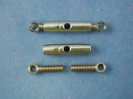
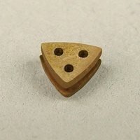
Thinking ahead, I decided to order some rigging parts. I need turnbuckles in two sizes. 6mm and 8mm closed size by the plans. The open sizes are 12mm and 18mm. I was able to find turnbuckles(bottle screws actually) of 8mm and 12mm. These should do nicely as they fit in the size range needed. Turnbuckles are adjustable after all. I need shackles of 3mm and heart deadeyes. It would be tedious to make so many tiny shackles and I don't like the method of making the heart deadeyes in the kit plans. I need heart deadeyes of 3.2mm and 2.4mm by the plans. It seems most places start shackles at 5mm and heart deadeyes at 5mm. The heart deadeyes I found in 3mm and 2.5mm. They're more triangular than tear drop shapped. Of course, its frustrating that no one place has all the parts. After much time searching I found everything at between two places. I also bought some parrels while I was ordering. Cast Your Anchor Hobby: https://www.castyouranchorhobby.com/ Cornwall Model Boats: https://www.cornwallmodelboats.co.uk/ Unfortunately, the shackle size I need is out of stock everywhere. I must say that Cornwall Model Boats is amazing. I have not found another place with such wide and complete offerings. They must have every model boat and part made. The prices are comparable to other hobby shop suppliers. Searching their site takes a little work. Like most of these stores, the search engine is not very good. I'm spoiled by Google. The big downside is they ship from Cornwall, England. The site sells in British Pounds. That means extra shipping cost and a currency conversion fee. It will probably take a couple weeks to get the parts too. On the other hand if there is something you need that's really hard to find, they have it. I'm still looking for shackles. Does anyone have suggestions? John
-
Thanks. I figure with my track record carving the likelihood was I would just screw up the next one anyway. It's a lot of work to get the asymmetrical shape and the jib stops which would have needed redoing as well.
-
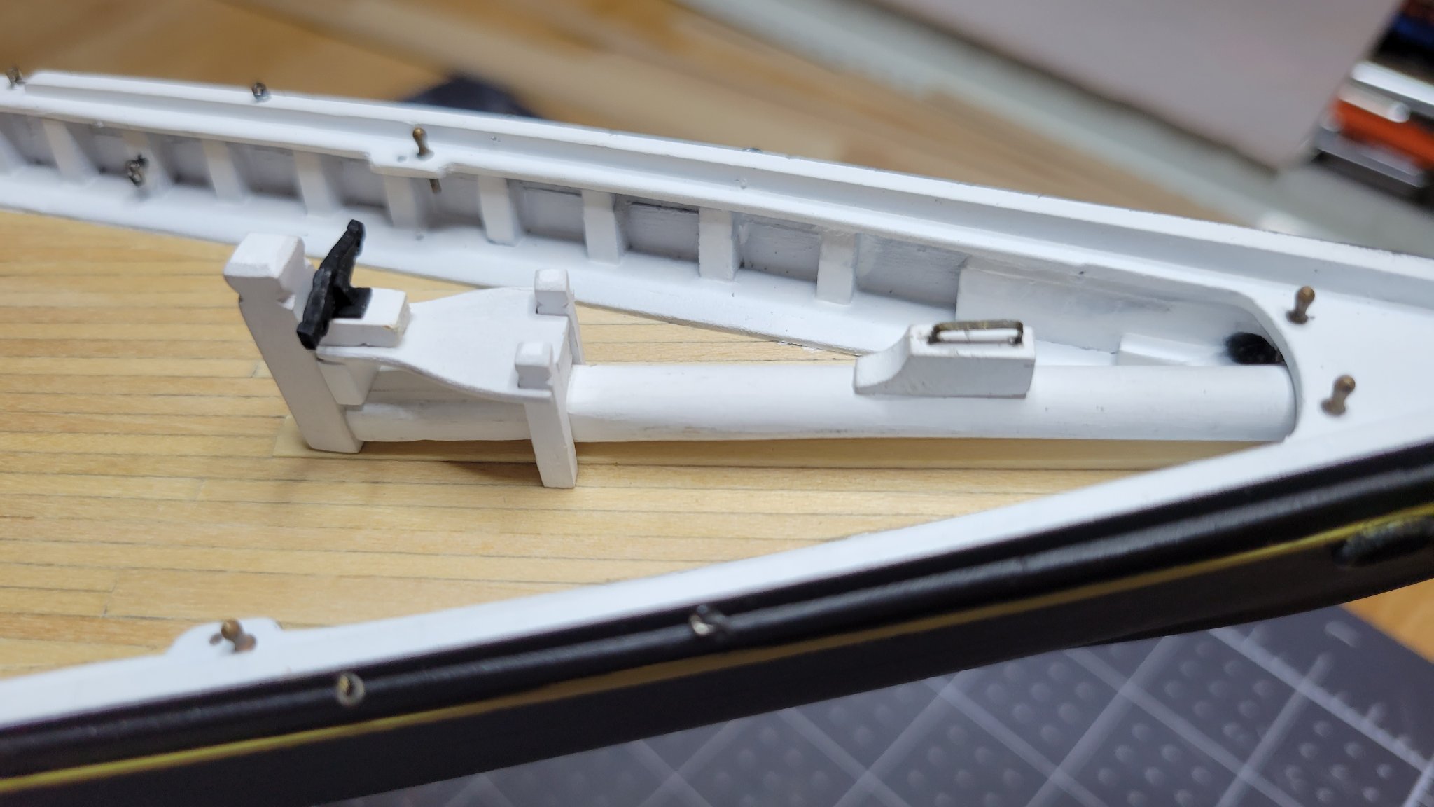
Today worked on the Samson Post platform and Bowsprit Bits. Also fabricated and installed the jumbo jib boom traveler block and gammon iron.