HOLIDAY DONATION DRIVE - SUPPORT MSW - DO YOUR PART TO KEEP THIS GREAT FORUM GOING!
×


JohnU
-
Posts
170 -
Joined
-
Last visited
Content Type
Profiles
Forums
Gallery
Events
Everything posted by JohnU
-
 Thanks! I wish there were an alternative to using this particular part. The other metal parts supplied with the kit aren't so bad. Retired Guy did a fabulous job but he has a mini-lathe and milling machine. He first built the windlass using the part from the kit. He did a really nice job of that, but it was still a badly made molding. A possibility would be using an inexpensive 3-D printer. A lot of parts could be easily made in excellent detail. The printing files could be a shared resource for builders. Perhaps a moderator on Model Ship World could start a shared archive. This would be a useful resource for many builders, not just for Bluenose. Producing these odd parts is cost effective using a printer. It could even be a little side business. If only the kit sellers would get on board and convert their production to 3-D printing the general level of quality could be improved. The downside of that is one of the reasons for pursuing this hobby is to use one's hands and develop skill. 3-D printing moves that to the realm of mental/computer skill. That isn't necessarily a bad thing. We use many types of tools in this hobby and 3-D printing is, in the end, just another tool. However, part of the fun is working with our hands and solving problems. John
 -
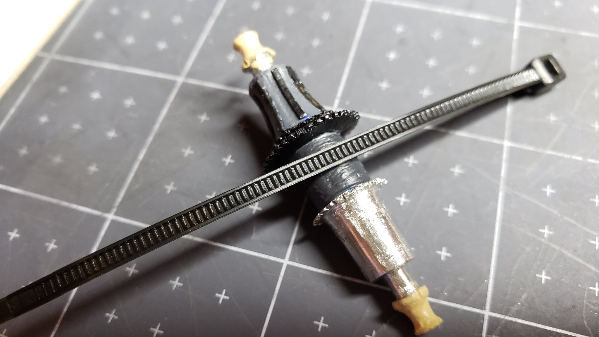
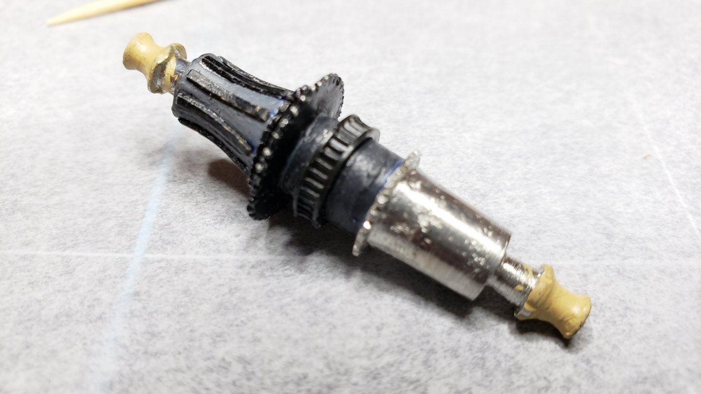
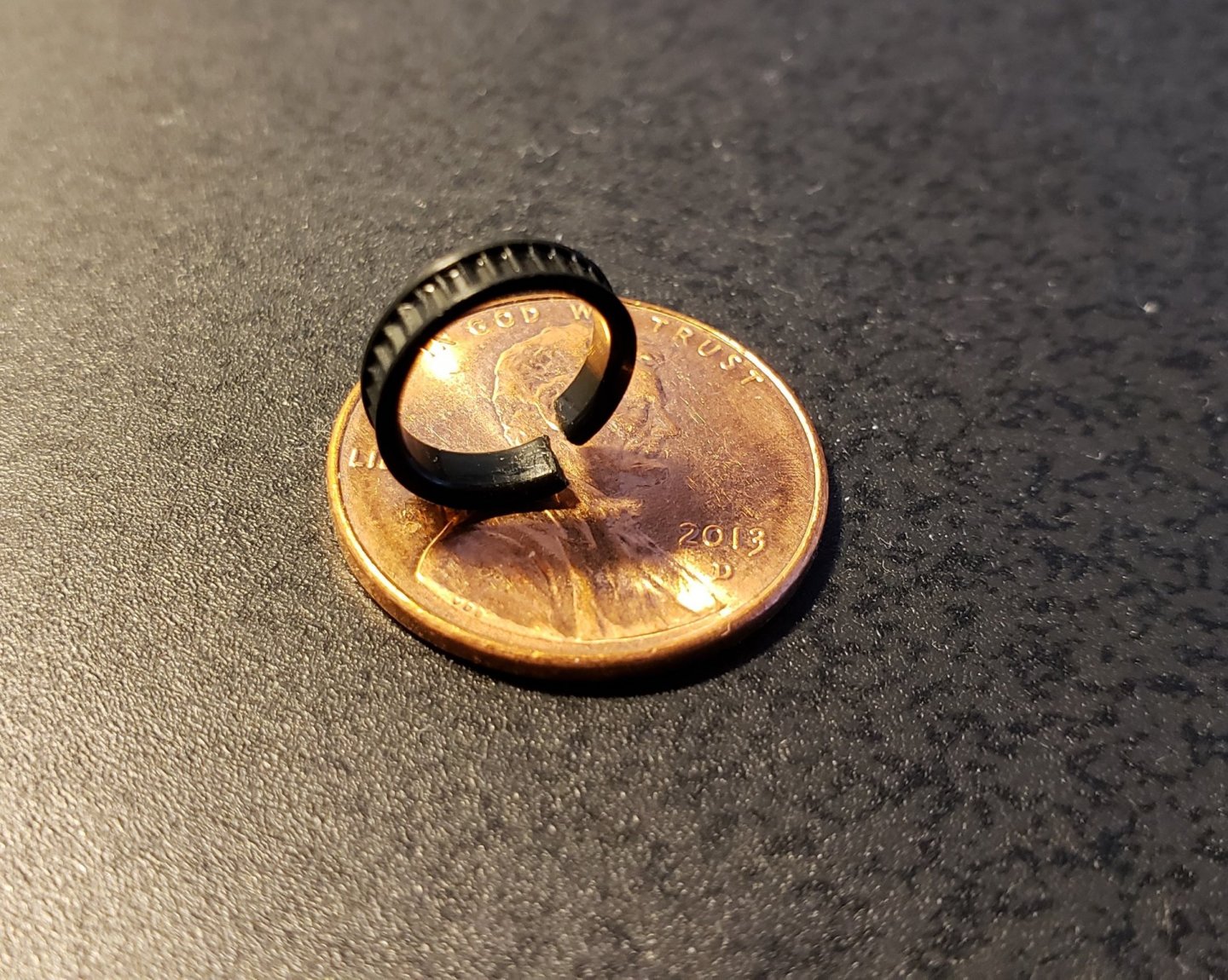
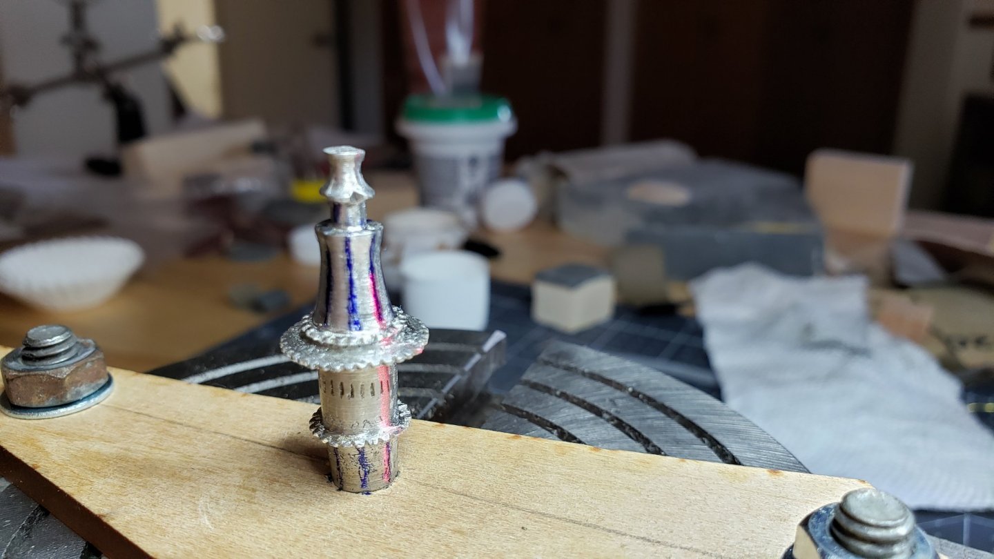
The windlass doesn't have good definition of the ratchet ring. The divots are not even uniform and it just doesn't look right anyway. Even painting a ring didn't help. Working with these poorly cast parts is frustrating. While thinking about how to make this part better it occurred to me that zip ties have a ratchet strip and are available in a wide variety of sizes. Rummaging through my project supplies I found one that's a near perfect fit. It also adds the detail of the side rings. It's just a little to thick, but that will make the detail stand out. Zip ties are a fairly hard, springy plastic. To get conformance at the diameter needed the zip tie was wrapped around a small screwdriver shank and heated with a heat gun until it was soft enough to relax the plastic. This produced a small diameter spiral after cooling. The zip tie was then expanded to the diameter of the windlass drum and trimmed to size. To ensure a bond I used high strength epoxy. The ratchet strip is unidirectional so it's important to get it the right direction to match the pawl on the samson post. This worked pretty well. Though I'm still dissatisfied with the piece. These metal parts are highly variable. The large gear from the boom crutch was well enough made to clean up and look decent. The large gear on this part is shabby. I'm also dissatisfied with the paint. I think I'll do that over before I install the wood whelps.

-
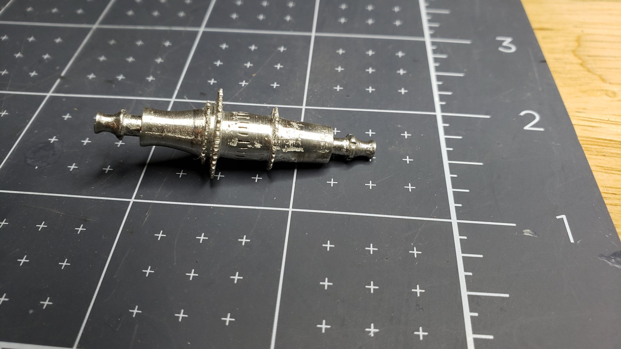
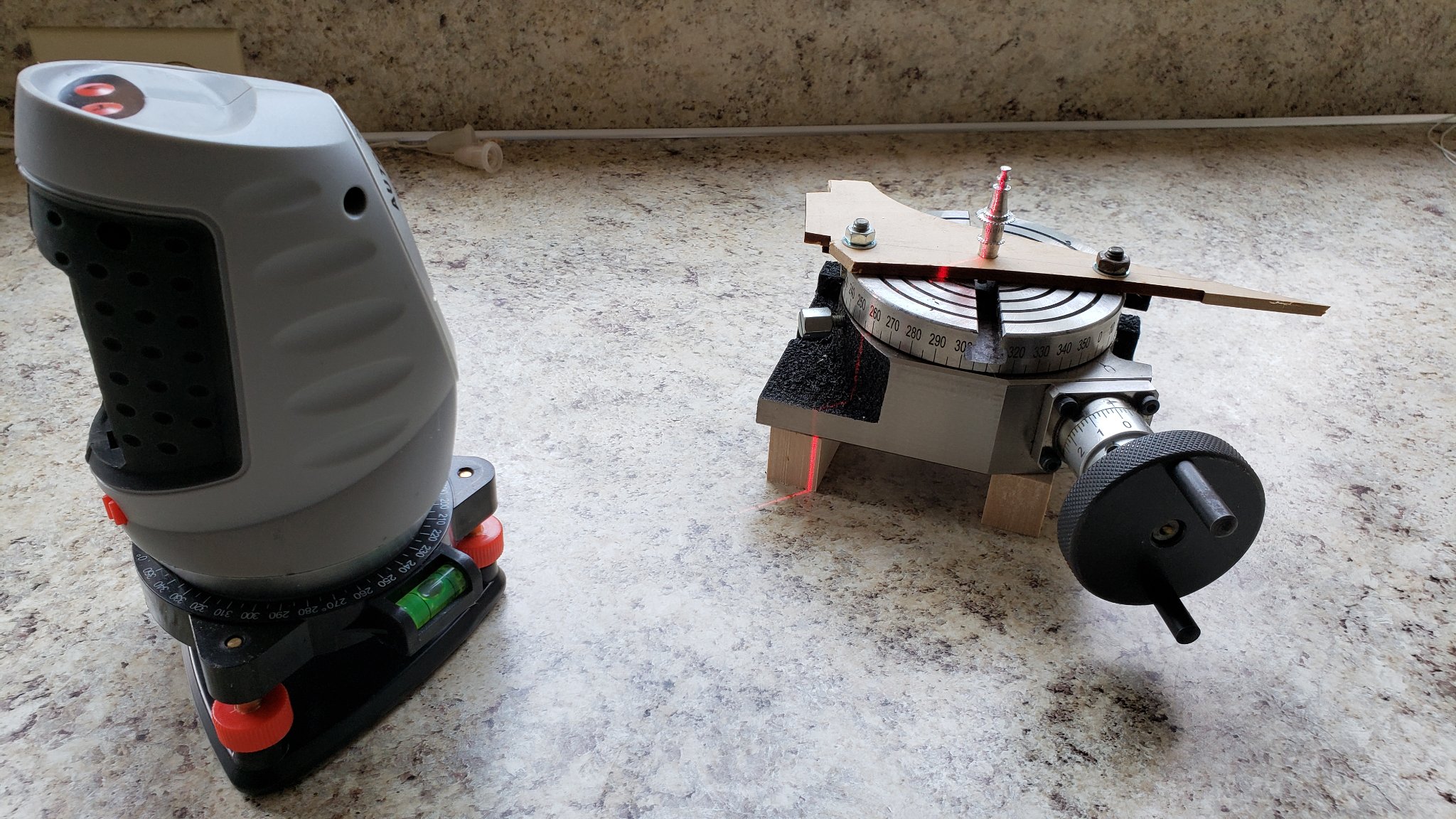
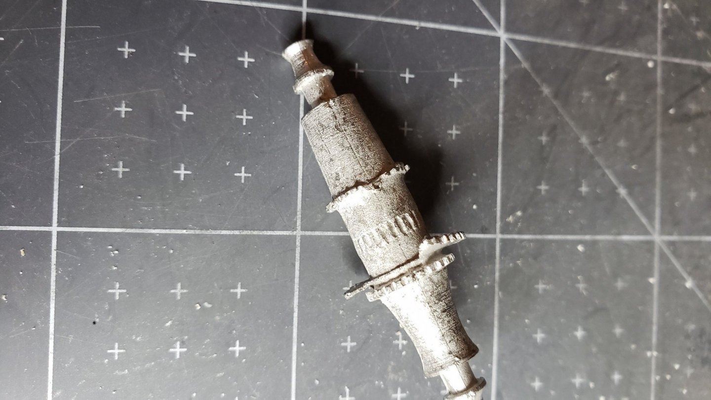
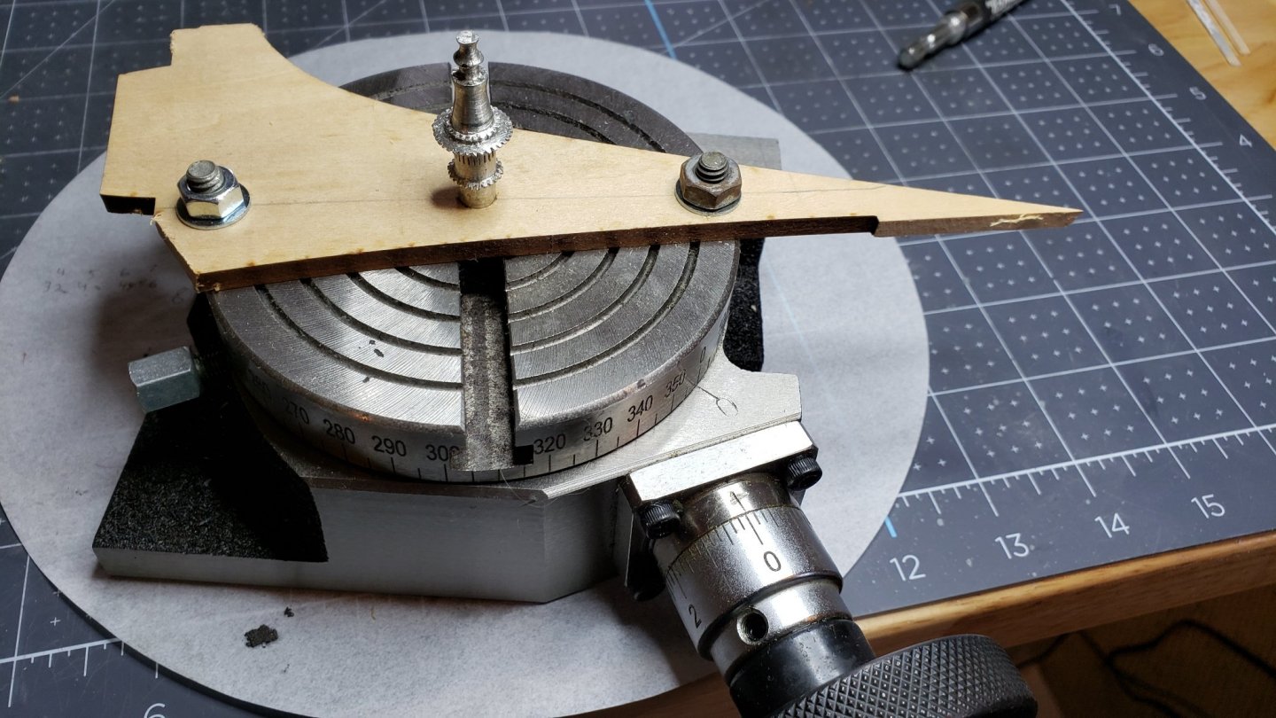
Not too much progress lately. I managed to drop my airbrush on it's needle. 🤕 The good side of that is it was a really cheap one and I got to order a nice Paaische TG series. While I wait for that I'm going to work on the windlass. I love Retired Guy's work on this part. He machines all the gears and little pieces to end up with a working windlass. Be sure to check out his blog. Unfortunately, I don't have all those nice machine tools and will have to make do with the Britannia metal parts supplied in the kit. The windlass that came with my kit was a particularly bad casting. You can see some parts of the piece are missing and distorted. Model Expo has a really great policy of supplying replacements parts free. Including shipping! Their warranty states they will replace a part for any reason; even a screwup on the customers part. I can't recommend their service highly enough. This alone is enough reason to purchase through them. F.Y.I the email address is: modelexpo.parts@gmail.com And the URL for the warranty info is: https://modelexpo-online.com/About-Us_ep_7.html After a couple weeks(Hey! It's free) the replacement part arrived. I was a little disgruntled. The new one was not very good. However it was, at least, complete. I was able to clean it up enough to pass cursory inspection after painting and assembly. Still doesn't look very pretty. The next problem was to mark the octants off for the steel and wood whelps. I'm not very good at eyeballing these things. Using an old rotary table I had($35 on Ebay) A jig was made to hold the windlass upright and centered on the table. I then used my home projects leveling laser in vertical mode to create a line on the part. A laser level has an amazing usefulness for many types of home projects. These are available pretty cheap at Harbor Freight and home stores. The one I have is Harbor Freight and one step up from the cheapest. It comes with a tripod and is compact. I just sat it on the workbench and leveled it. A fine point marker in a contrasting color was used to mark the octants. Looks pretty rough at this stage. It'll be OK once painted and all the whelps are installed. Still, it would be nice to have all those machine tools and do it right.


-
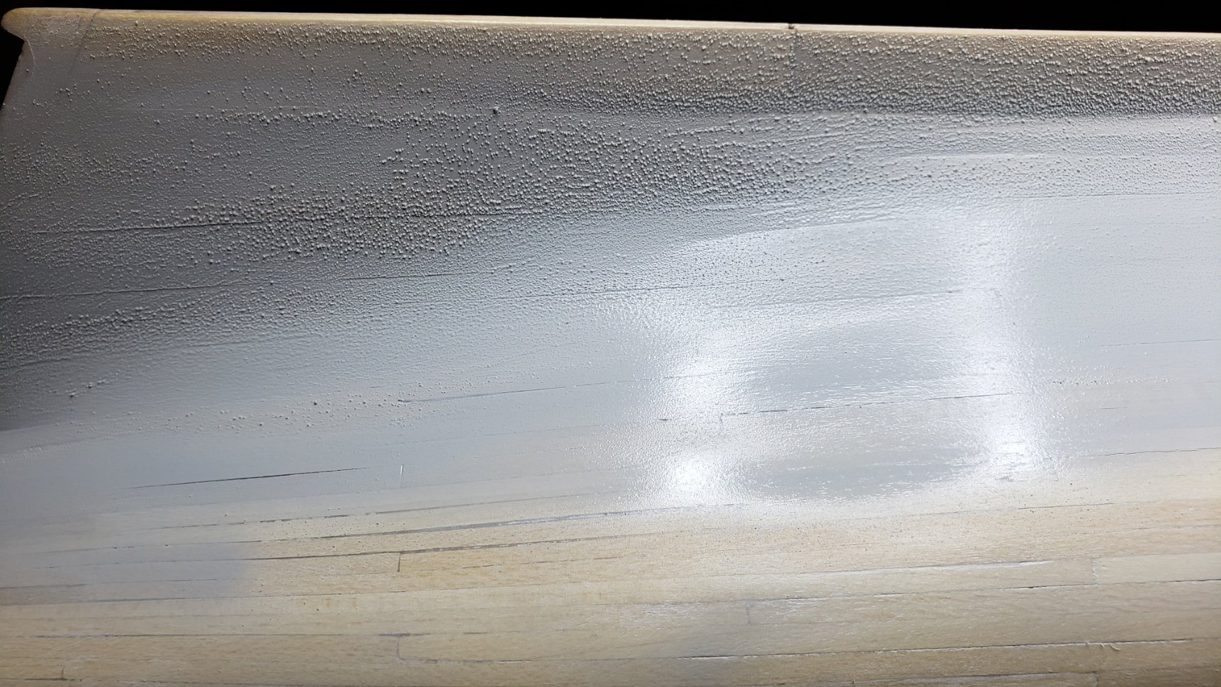
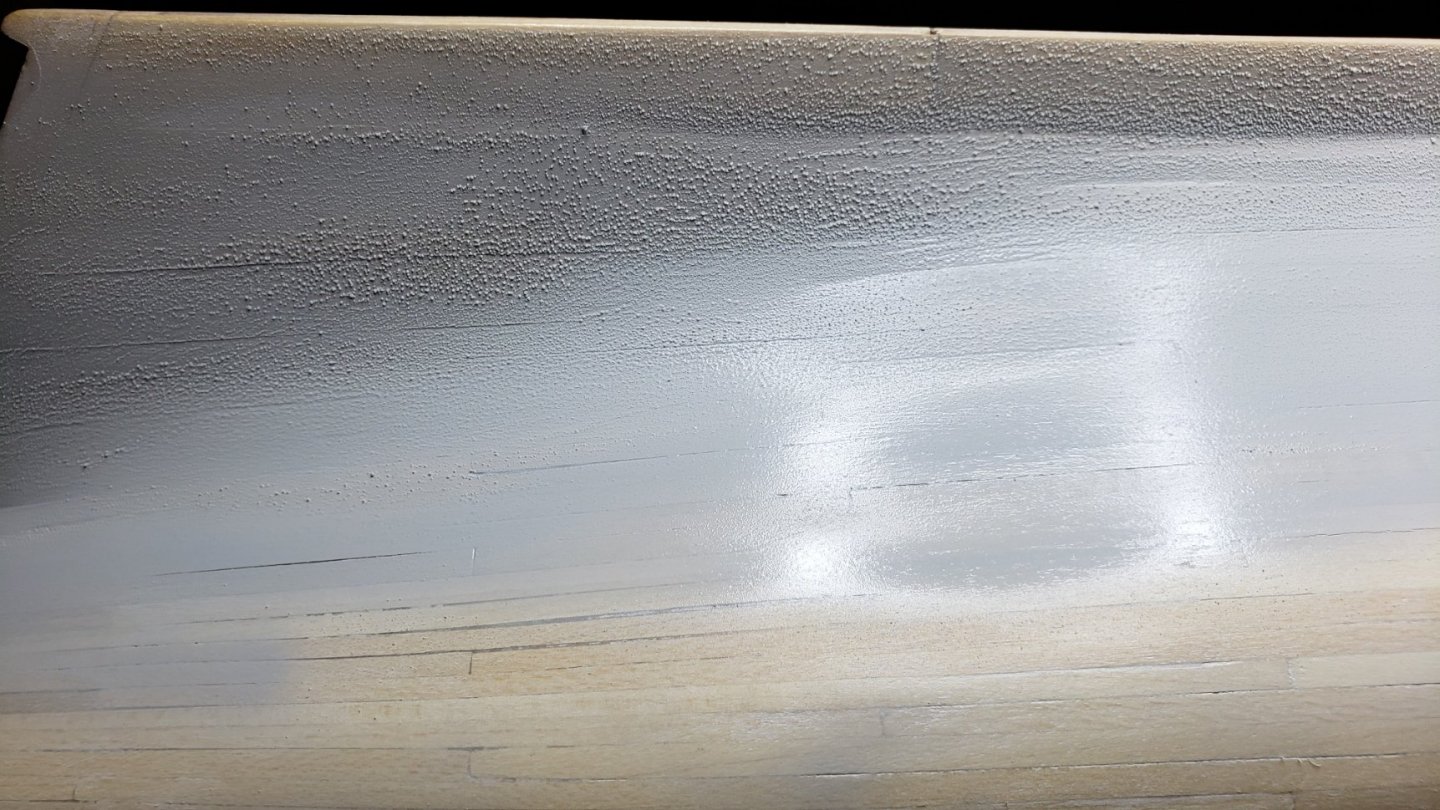
Thanks for the helpful replies. I now suspect there was an incompatibility between the sanding sealer(Shellac) and the lacquer thinner. I originally went to my local hobby shop for primer and thinner. They are normally very knowledgeable and carry quality supplies. I requested Tamiya primer and Tamiya thinner as advised on this forum. The clerk seemed to know just what I wanted and supplied my request. Thinking this would ensure compatibility, I went home and eagerly did the recommended 50/50 mixture. To my surprise the paint suddenly turned to a large jelly-like glob on my mixing stick. I pulled the glob out with the stick and most of the thinner was left in the mixing jar. Well! threw that mess out. I then read the label directions on the Tamiya primer bottle. It clearly said to use "lacquer thinner" for thinning. The result is what you see in the picture. As near as I can tell the primer they sold me is lacquer based and the thinner is water based. Though I told them specifically what I wanted it for. There was some strange chemical reaction. I will be making another trip there and I'll bring everything, including the glob, and see what they have to say. Normally they are very good. I'm sure there was just a slip-up in what they gave me. John
-
I'm new to airbrushing. Trying to figure this out. I mixed Tamayia primer 50% with lacquer thinner. When I spray it on it looks OK. After about a minute it started blistering like the picture below. What am I doing wrong?
-
Hi Rachel, The Bluenose should not require drop planks. I tried to follow the suggested layout on the plans. This turned out to be a mistake. I ended up with the planks too wide at the upper part of the stem and had to taper them too much at the lower part to compensate. The planks under the counter also ended up a bit thin. Lesson learned. There are several good examples of planking the Bluenose in the build logs. Much better than mine. This was my first time planking and I learned a lot. John
-
Thanks Eric, I've been working on some volunteer stuff I do and had to put this on hold for a while. Hope to get back to it soon. John
-
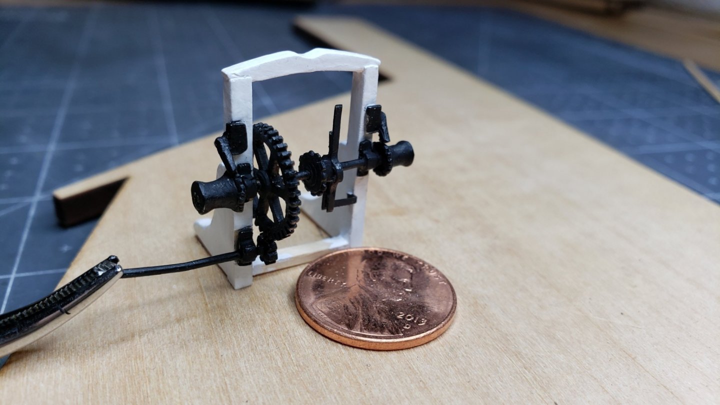
It was finicky working with such small parts. Need a magnifier and tweezers these days. Age takes it's toll. The kit has an amazing number of small parts for the mechanical apparatus. But there are inexplicable parts left off. The gear side of the clutch is provided, but not the lever side or the lever. This is true in general for this kit. overall it's nice. They leave odd bits out. Usually chain is supplied but this kit doesn't have any. Things like that. Anyway, I made the lever assembly from the flat brass wire provide with the kit. This was a little tricky as there are three pieces, two of which wrap around the missing clutch cylinder. To simplify I wrapped them around the hub of the clutch gear. It's not a working assembly and it looks correct. I used CA glue to assemble the parts. Here's the result: Needs some touch up. The Britannia metal parts are a bit crude when looked at close up. The camera reveals details and textures that I don't see with my naked eye. It looks good from normal viewing distance. Note: the sanding sealer and sanding before assembly completely got rid of the fuzzies. However, using a brush doesn't provide uniform coverage as airbrushing would.
-
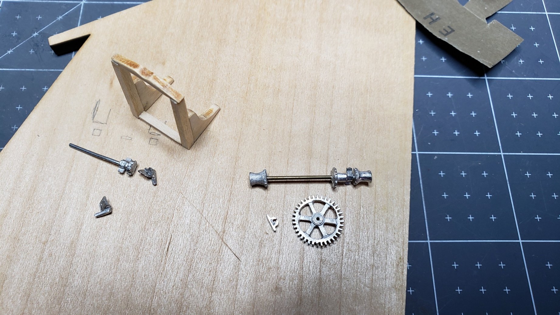
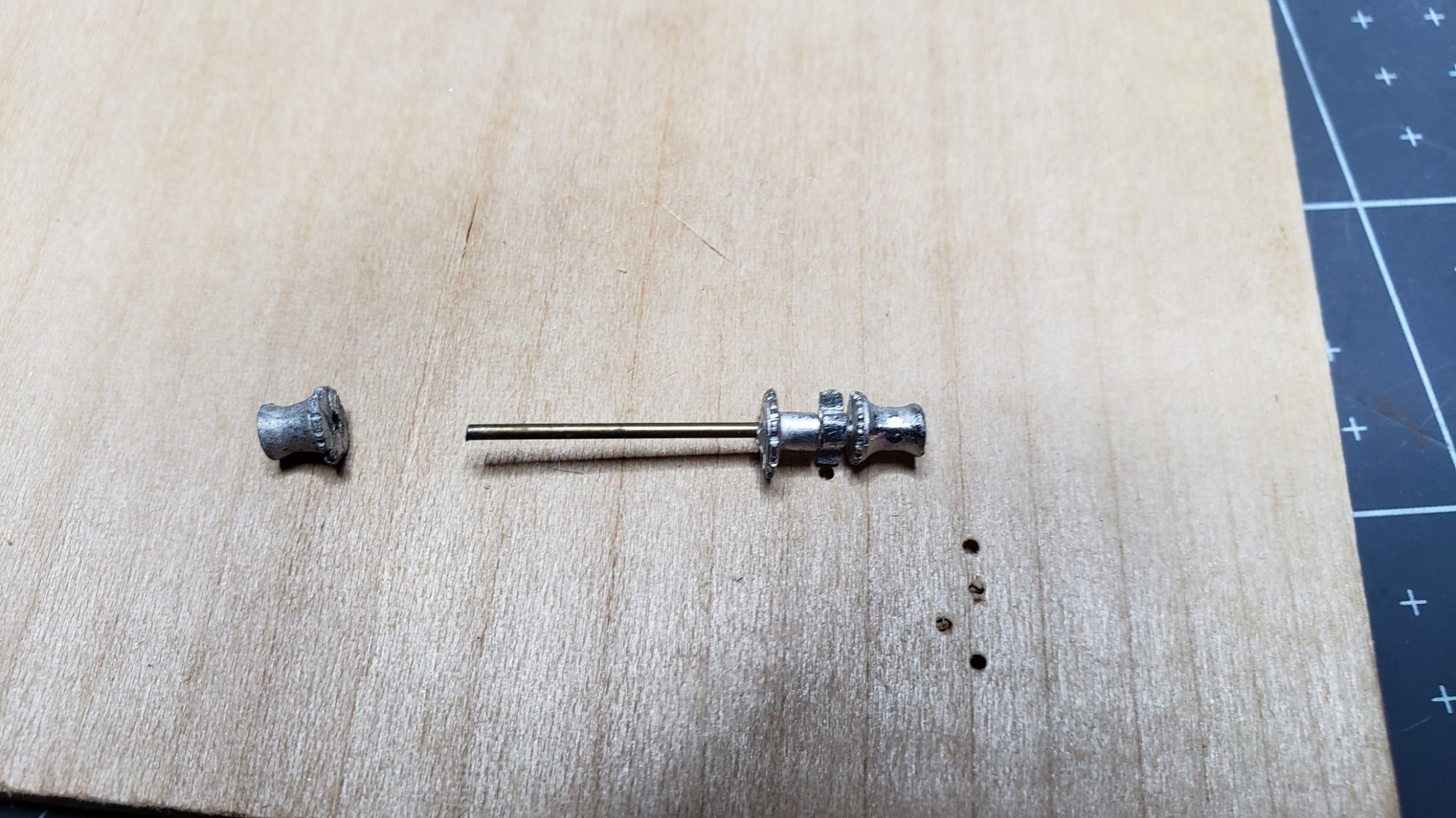
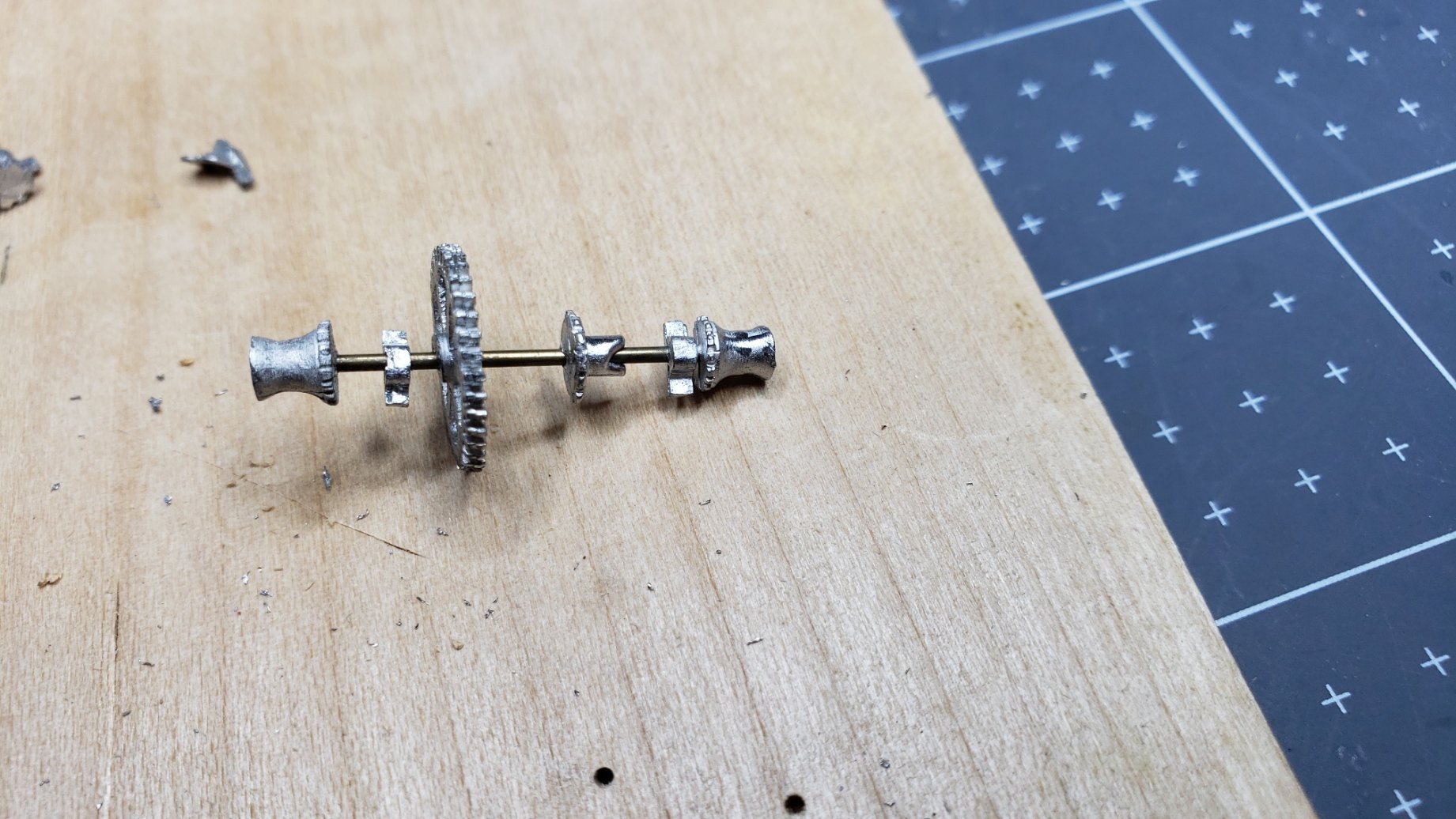
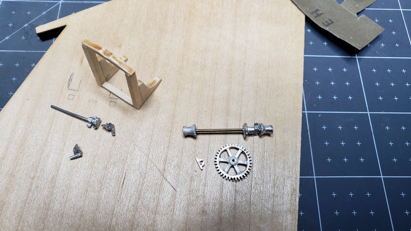
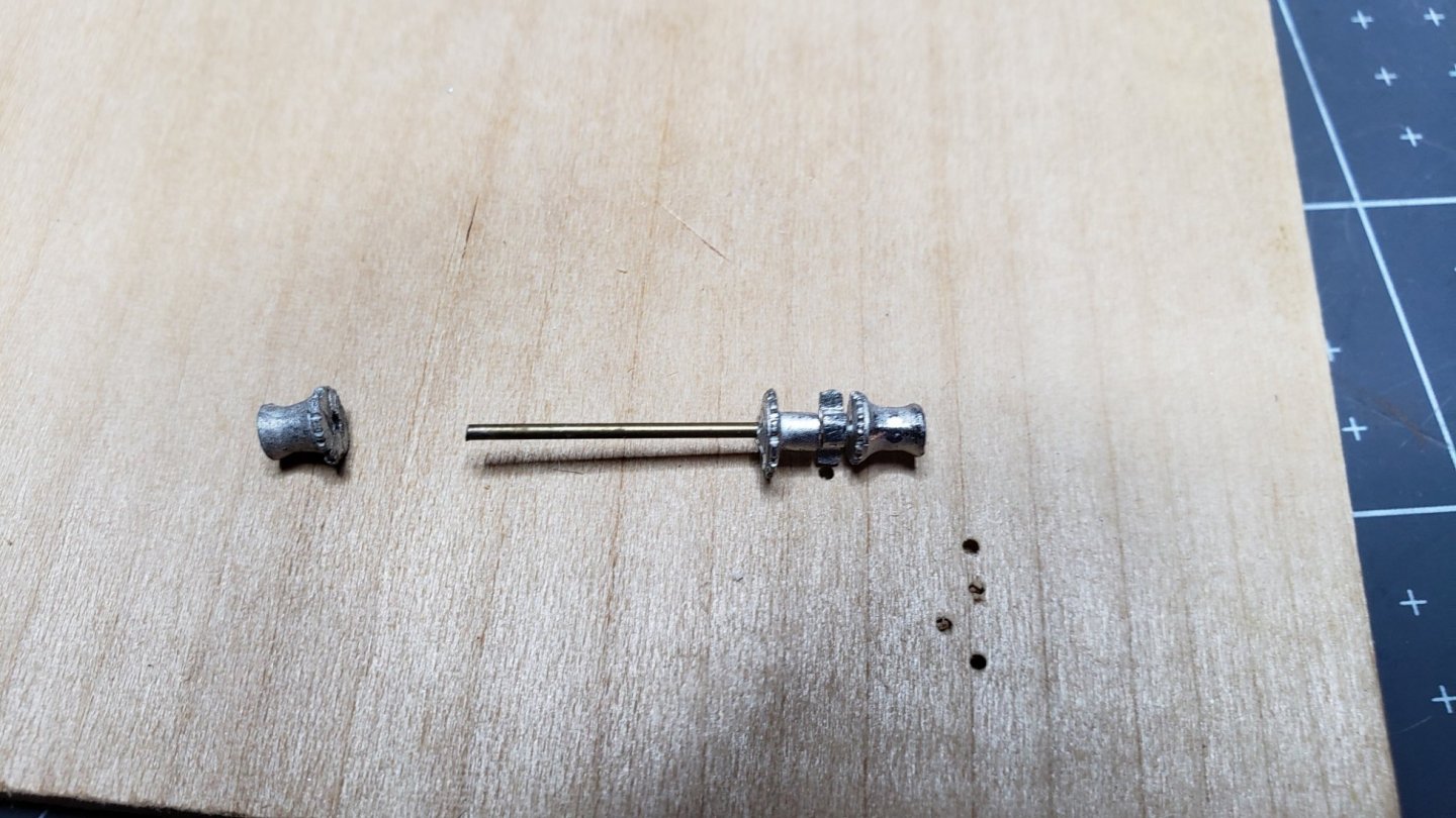
While waiting for paint to dry on the hull, I started the Jumbo boom crutch with it's gears. The Britannia metal was previously cleaned and trimmed. As usual they are not of the best quality. Following my experience with the main mast pin rail The parts were prepared for painting -before- assembly. Quick work was made of sizing the two posts using my handy-dandy upside down mini plane. Wonderful tool! The knees were glued to the posts then all parts sanded with 400 grit. A temporary block was glued between the crutch legs for strength during assembly. This will be removed when the part is glued to the deck. Shellac was applied as a sanding sealer. Then Sanded again with 400 grit. I used Tamiya flat white applied with a brush. Three thin coats were applied to get coverage and keep the paint thin. Much better result than the pin rail. The next challenge was the axle for the gears. The port bearing bracket and the large gear were supplied as separate items and the winch drums, clutch gear and Starboard bearing bracket were molded onto the axle. That left no way to put the port bracket and large gear on the shaft. Some experimentation on waste Britannia metal yielded the fact that it melts at soldering temperatures. Heating the shaft gently with a soldering iron softened the metal enough to slide the winch drum off the shaft; allowing the big gear and bearing bracket to be installed. The winch drum was drilled through to allow adjusting the fit.

-
Thanks for the tips! I did try sealing and sanding the pin rail as an experiment. I used shellac as recommended in several posts. In retrospect it would have been better to seal and sand before assembly. It's hard to sand such a delicate assembly. The result was better than simply painting basswood but not quite what I would like.
-
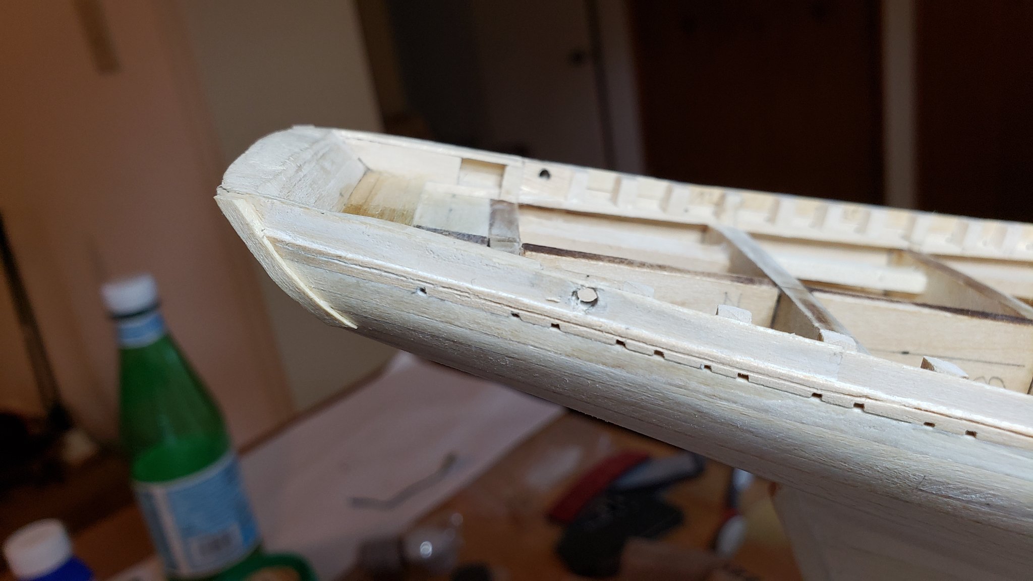
When reviewing the pictures of the Bluenose in the Nova Scotia archive, I discovered a discrepancy in the actual ship versus the plans. The fashion piece is not as long as shown on the plans and is squared off on the end rather than cut at a slant to follow the planks. It's also not clear in the photos but the end may have been tapered to the plank. The longer piece shown on the plans is, to me, more attractive. Builders choice for this.

-
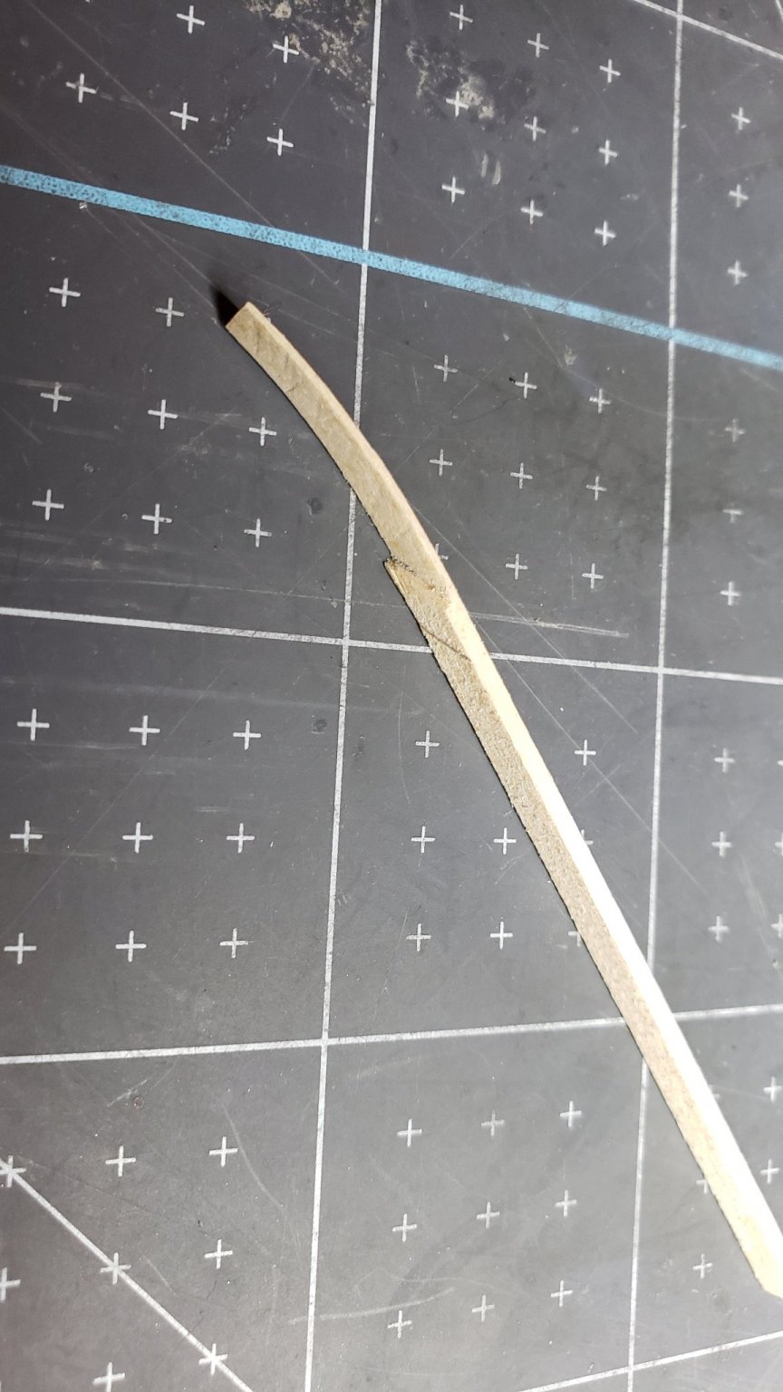
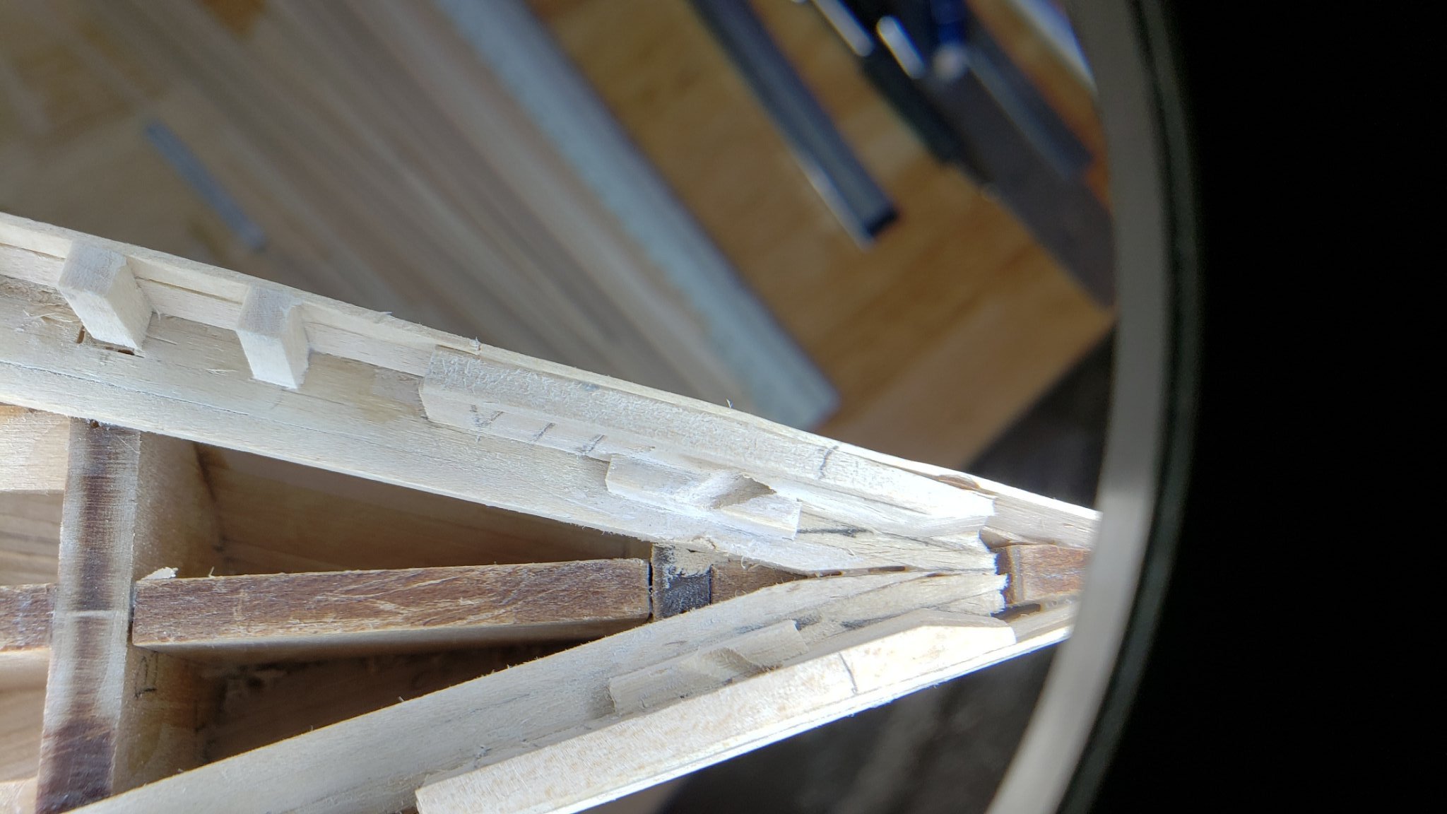
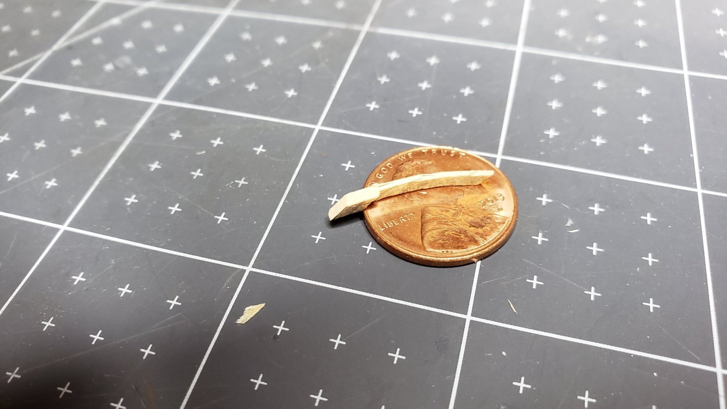
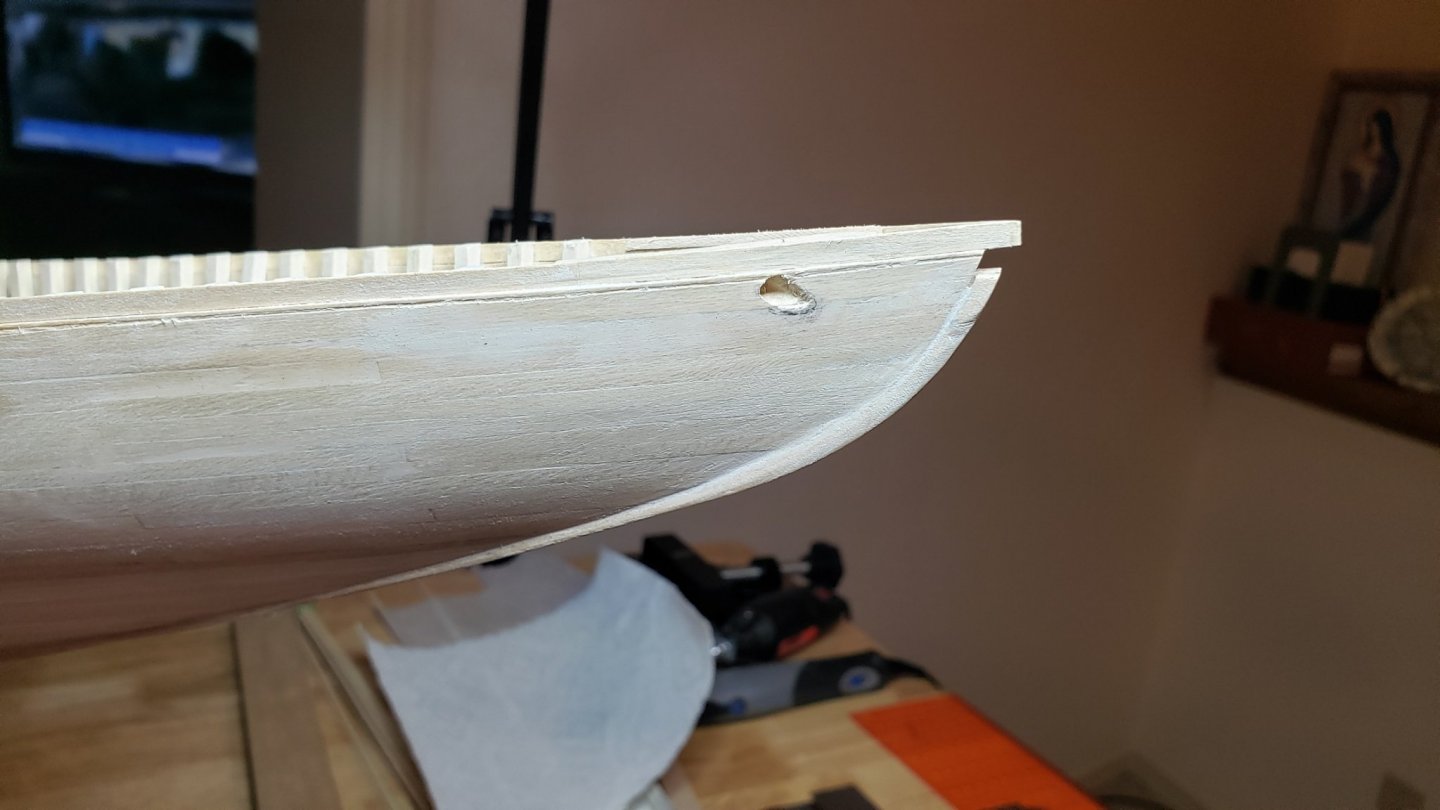
Now back to the hull. There are still some odds and ends to do before painting. Due to my carving skill I had some trepidation about the "fashion piece" at the fantail. This is a part with complex curves and a odd shape. It's also very tiny. The plans do not have any detail aside from a front and side view at scale. The procedure I decided on was to use a hull plank and cut it down to size and shape. A mini disk sander was used to take the thickness of part of the plank to the require size. A chisel blade was used to cut the angle and trim the thick end to dimension. The piece was fitted to the fantail and trimmed to size and angle. A steam iron was used to soften the wood for bending to shape.

-
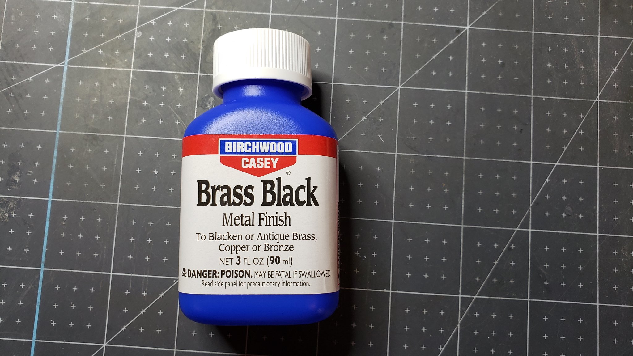
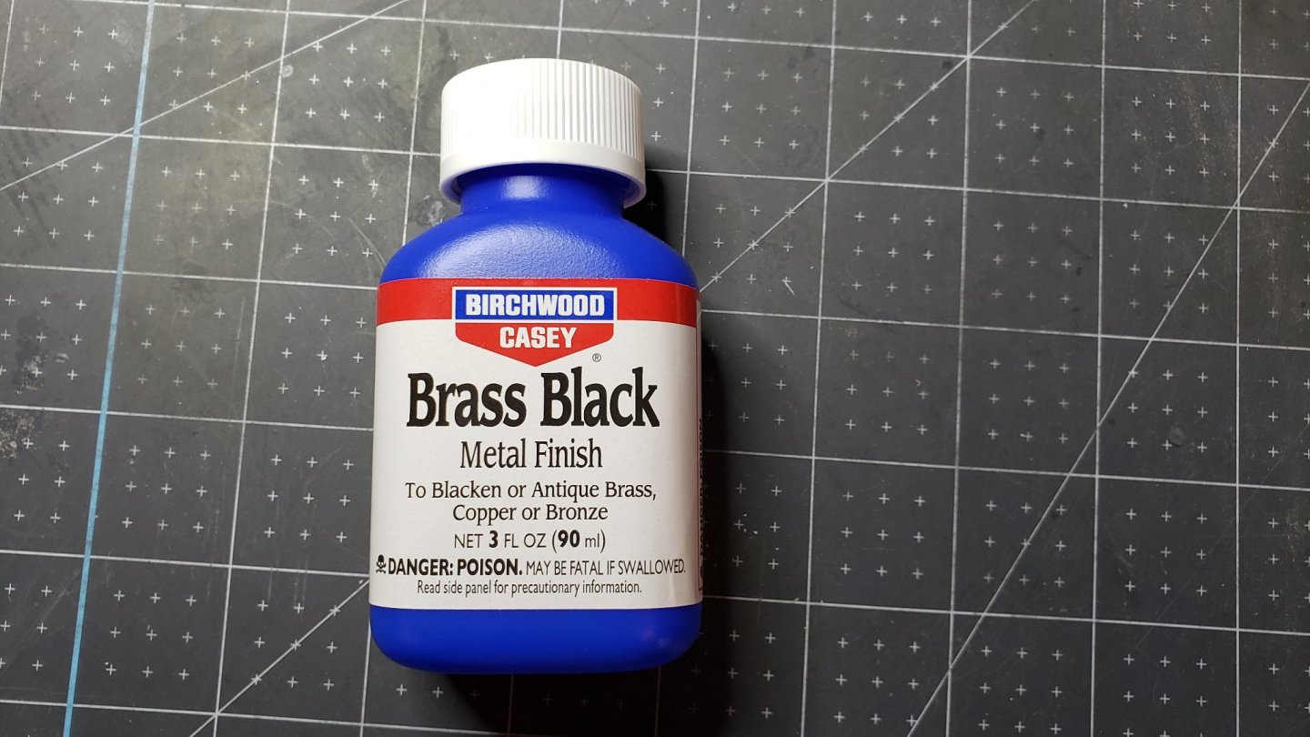
The mainmast pin rail/boom crutch is painted. Still not as nice a finish as I'd like. Suggestions for getting a smooth finish would be welcome! This was my first attempt at airbrush. It took some practice, especially getting the paint thinned correctly. That seems a critical step. I purchased the Model Expo Bluenose paint set before I had read the tips and techniques forum about airbrush paints. There seem to be a lot of negative comments about Model Expo paint. The primer didn't work very well, but the white paint sprayed OK. Of course I'm a newbie at thinning which might have something to do with it. In the tips and techniques forum I had seen a lot of discussion about blackening brass. There were lots of complex procedures and noxious potions. Some science and some alchemy. Not something I was looking forward to. I saw a product for blackening on Model Expo's site which looked simple. Turned out this was the "right stuff". I simply dumped the brass parts directly from their packages into Alcohol to degrease, dried and dunked them in the blackening solution agitate for a couple minutes, rinse with water and dry. The hardest part was separating all those tiny parts afterward. The parts were a uniform, flat black. They are easily burnished is you want a little sheen. The finish seems durable.
-
There was one problem though. The extra thickness of the cardboard made the legs too long. That caused the pin rail to slant. I had to cut the cardboard away around the legs where it needs the reinforcement most. Of course it broke in the weakened area around the holes. Fortunately, I was able to glue the part back together using plenty of glue on the underside to strengthen it.
-
I took a look at the survey. It's hard to make judgements among kit suppliers when one has limited experience. I've only built two brands of kits. I can't rank against other brands without experience. I would prefer to do a quality rating type survey. For instance: 1. What ship kit are you rating? List of kit suppliers... 2. Were the instructions adequate? Rate from 1= poor to 5=excellent 3. Quality of parts supplied? Rate from 1= poor to 5=excellent 4. Rate the completeness of the plans supplied? Rate from 1= poor to 5=excellent 5. Customer Service? Rate from 1= poor to 5=excellent 6. Accuracy of model and scale? Rate from 1= poor to 5=excellent 7. Ease of construction? Rate from 1= difficult to 5=anyone can do it 8... Then a space for general comments at the end. Over time a database of ratings is built up and can be made searchable. Kits could be ranked automagically from the database. I did make use of build logs and other forums when I was deciding which kit to buy. I commented on what I found when I started my Bluenose log. I think this survey forum is a great idea. It would be very helpful. John
-
I'd like to put in a plug for Model Shipways customer service. One of the britannia metal parts supplied with my Bluenose kit was incompletely cast. Model Shipways has a statement on the Model Expo web page saying they would replace any damaged or lost parts for free: https://modelexpo-online.com/About-Us_ep_7.html It took a little exploring to find the right email address, but they made good on their promise. A replacement part is on the way, no charge. Model Shipways states in their advertising that extra wood is included in their kits. Another nice perk. Aside from the poor instructions, this kit has more than met my expectations. I let the instructions slide though, the kit is intended for more advanced modelers who should need less instruction.
-
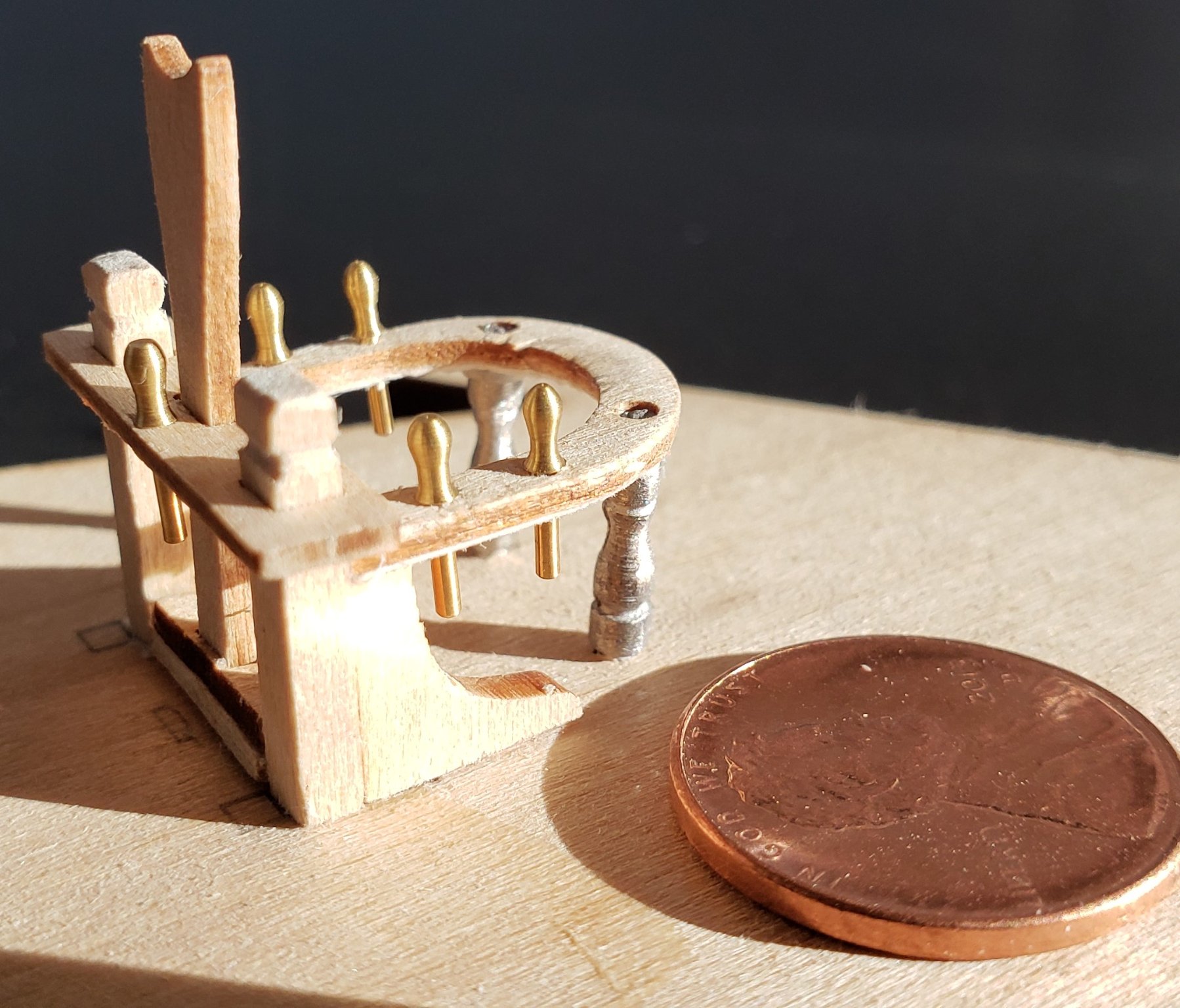
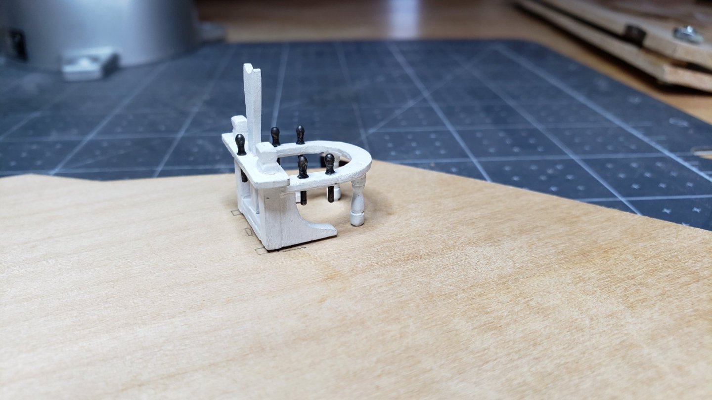
Took a break from the hull. Wanted to do some detail work for a while and try out my airbrush. I assembled the pin rail and boom crutch for the main mast. The laser cut parts are very delicate. Several blogs mentioned the horseshoe shaped piece as being particularly fragile. Most builders have simply made a new one from sturdier stuff. Being bad at carving, I decided to follow the advice of one builder who cemented cardboard to the piece to increase strength. This worked out well. After I attached the cardboard I left the center uncut until sanding was done. This provided something to hold on to while sanding. Sure enough, after I cut the center out and tried to sand the inner edge it broke.😞 Fortunately the cardboard held it together and I was able to simply apply glue to the break and it was good as new. Stronger probably. The Britannia metal legs are of the usual quality. Takes a bit of filing and fussing. I would have made new ones from wood if I had a mini-lathe. The supplied brass belaying pins are excellent. They will just need cleaning and blacking. The brass looks nice but is not authentic. They may be a little bigger than scale too. That's not noticeable from viewing distance. Ready for finish prep and paint;

-
I had a few springy planks where the edge glue missed. This is a problem as they can never be sanded smooth with adjacent planks. The springiness means the pressure of the sanding block is less on them and they always end up just slightly above adjacent boards. To fix this I spread a layer of PVA glue on the inside of the hull where the boards are springy and rubbed it in. After the glue set the planks were solid enough to be sanded even with the adjacent planks.
-
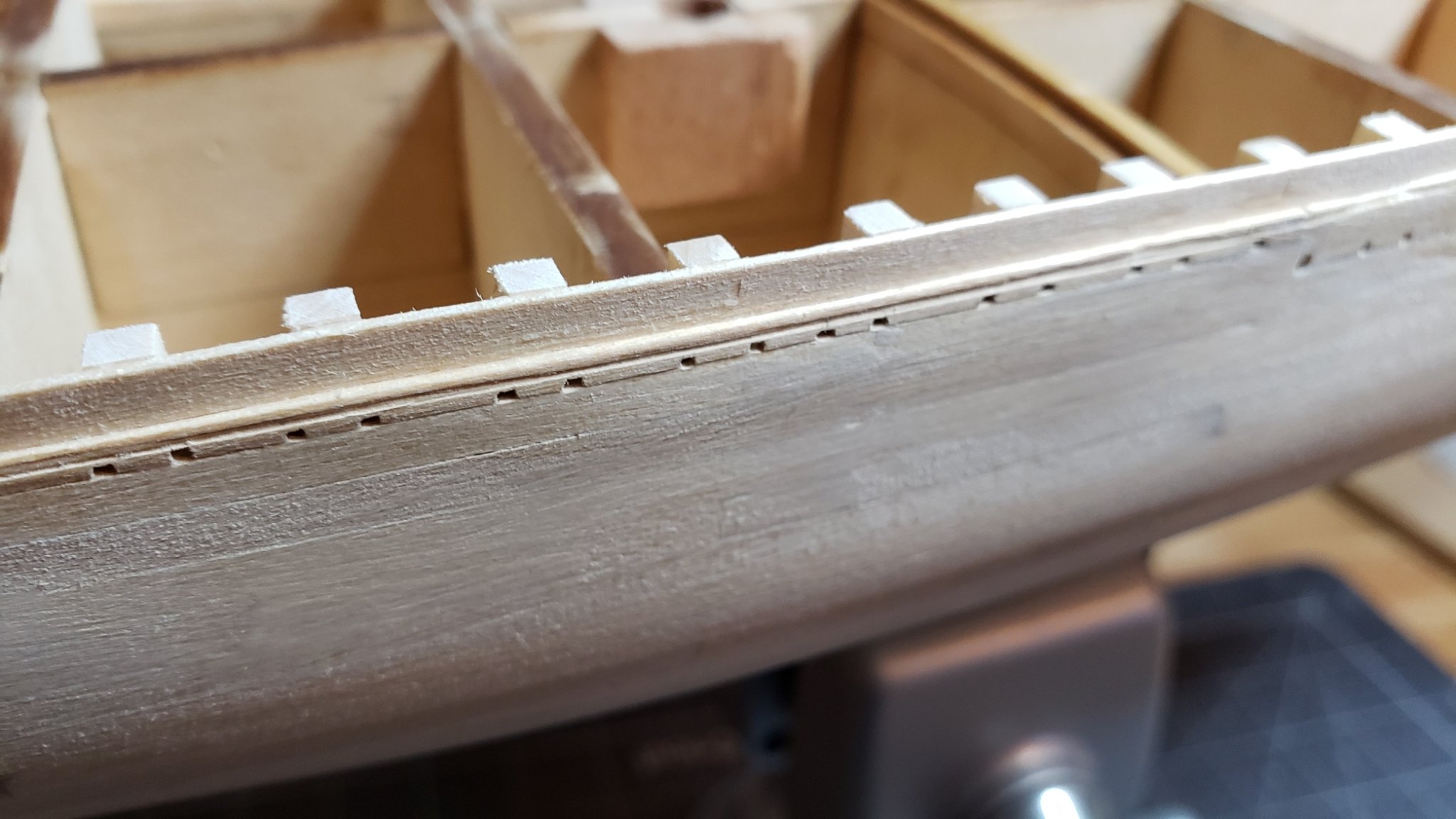
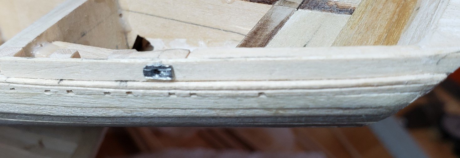
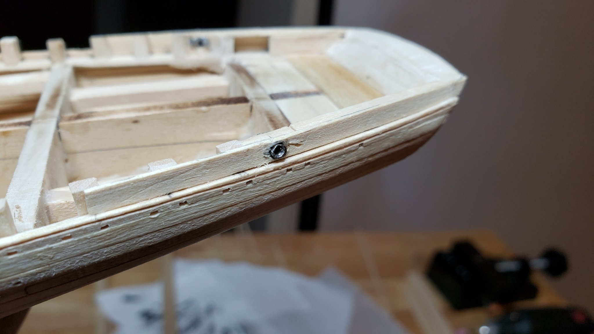
The hawse holes were created yesterday. It was a little tricky getting the position and shape right. Takes a bit of filing. I used the supplied Britannia metal hawse rings to get the shape. Getting the right angle and position is a little tricky. The hole was made by starting with a small drill and working up to the full 1/8 inch gradually. The basswood is soft and the drill bits tend to grab. The final hole size was done chucking an 1/8" drill in a pin vise and drilling carefully by hand. Still needs some cleanup after the hawse ring is mounted and the first pass of paint. Next is to cover up all the ugliness with filler and fine sanding.
-
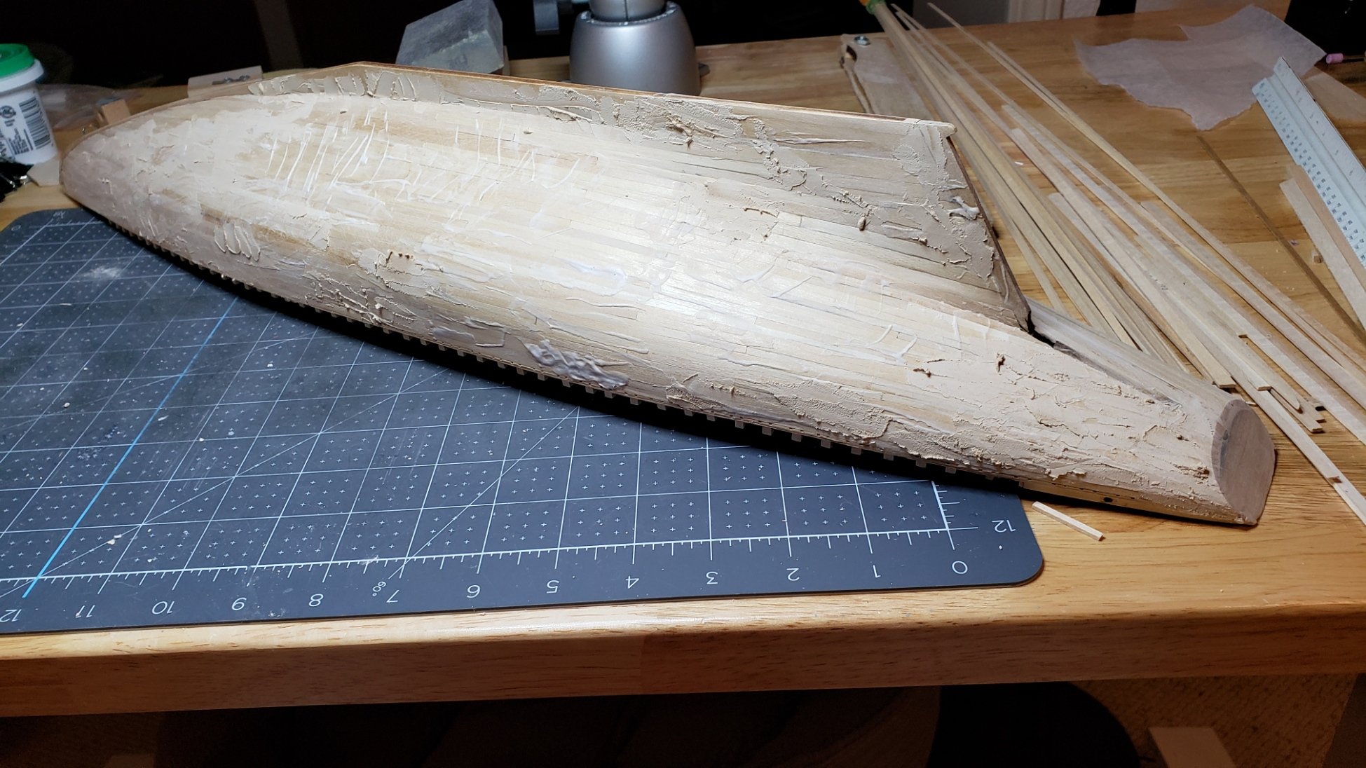
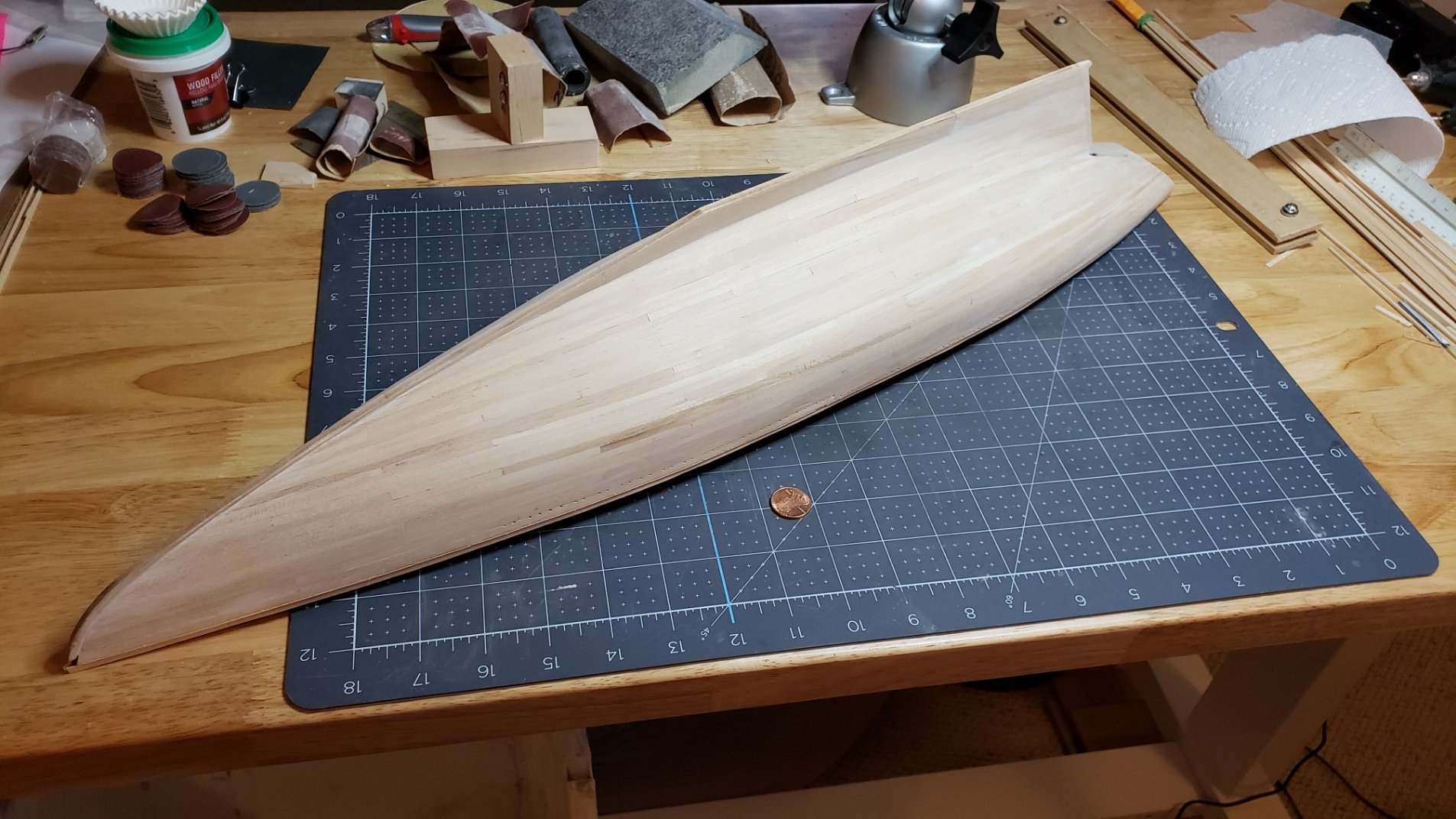
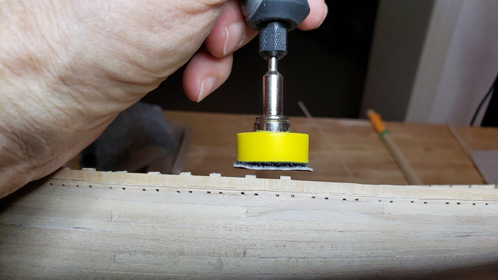
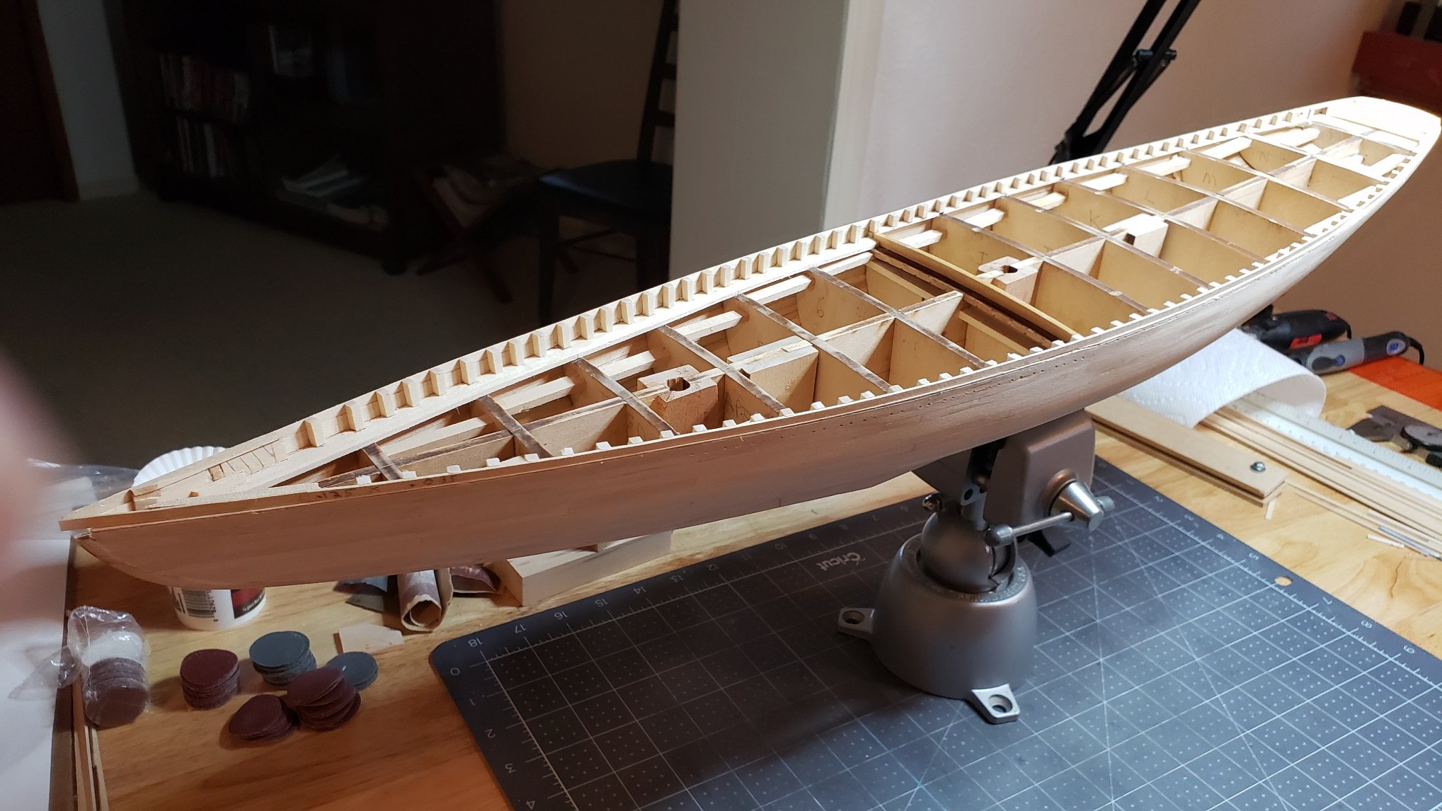
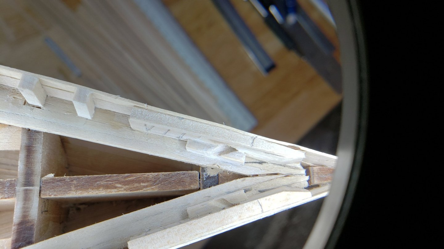
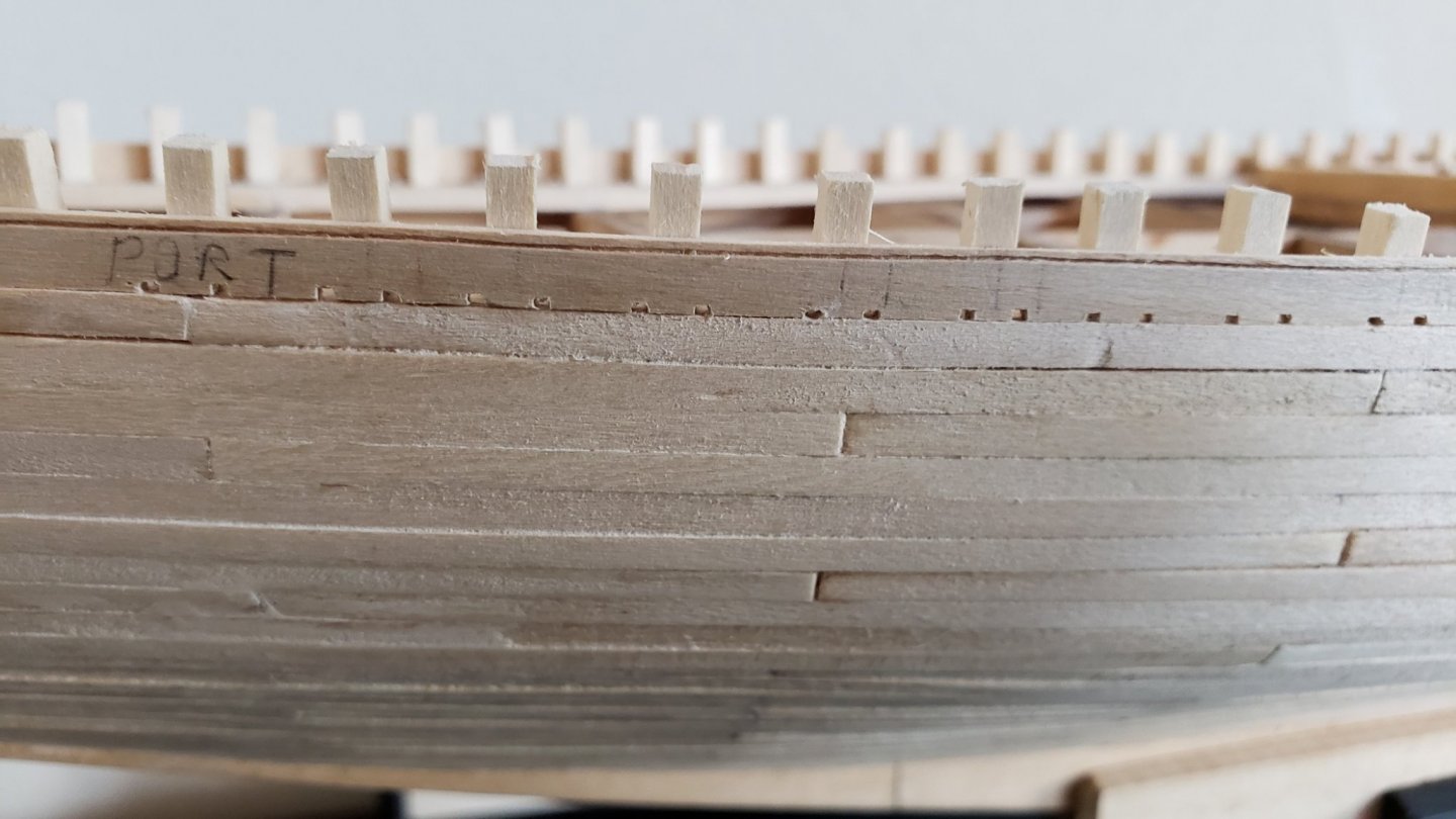
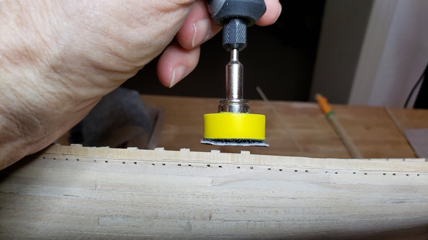
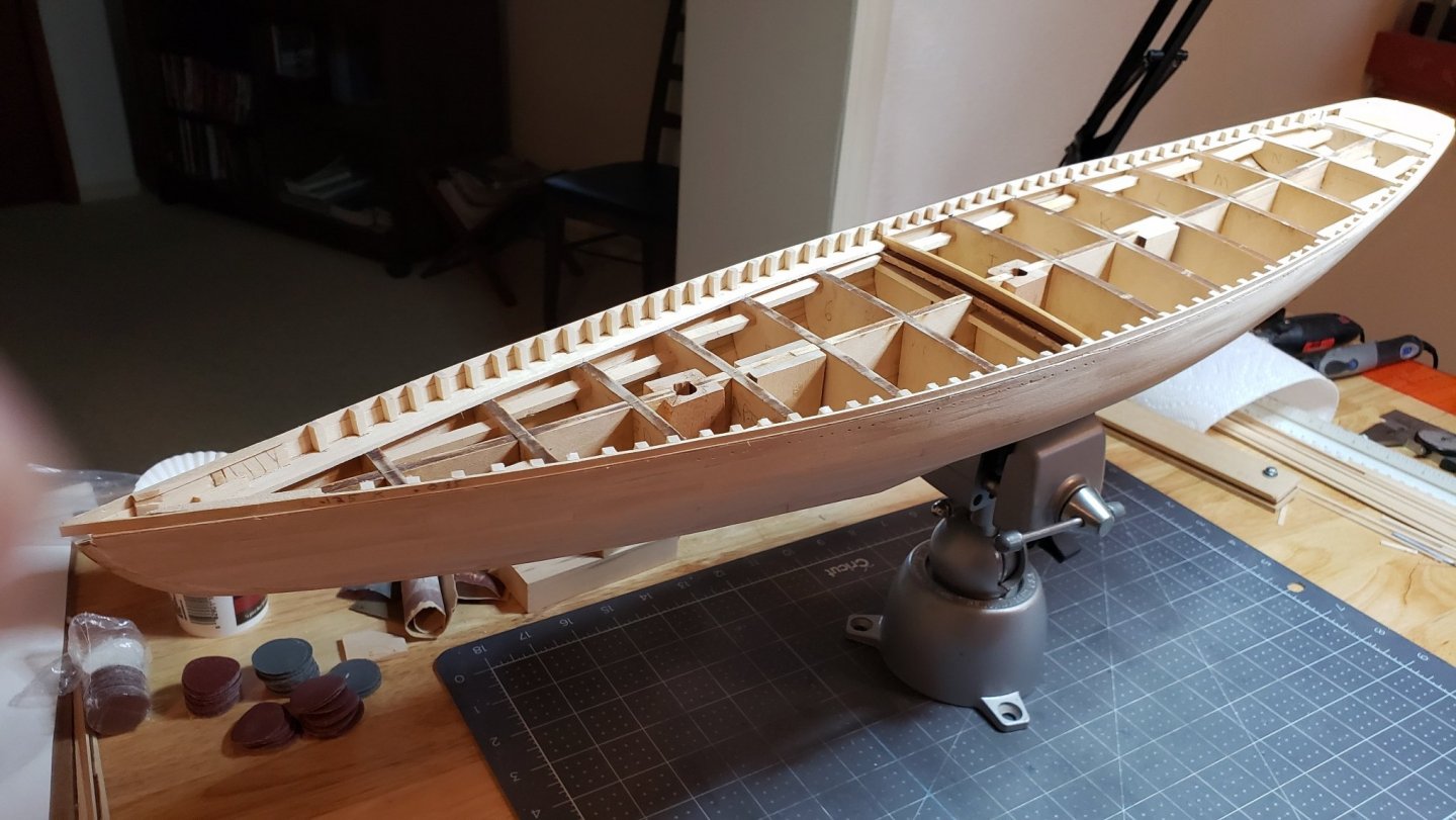
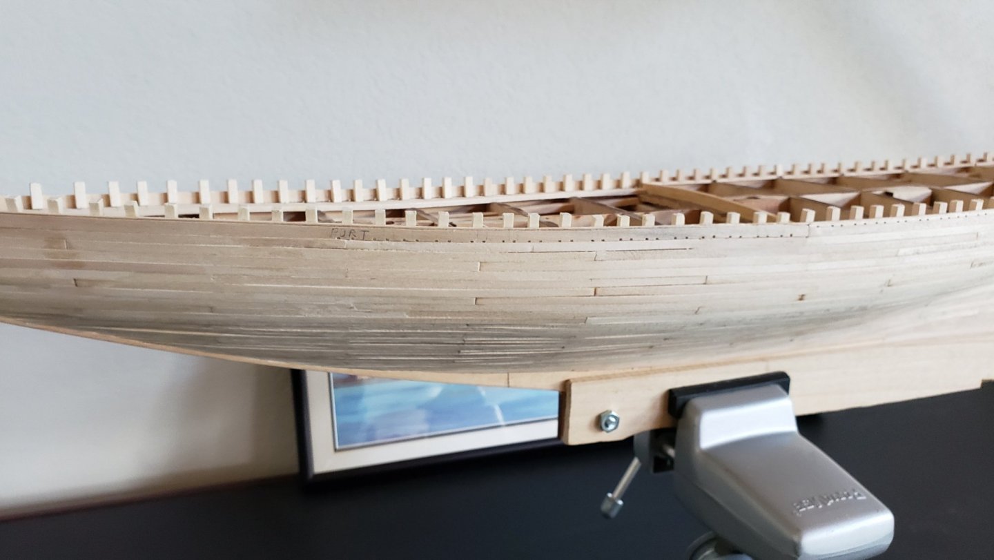
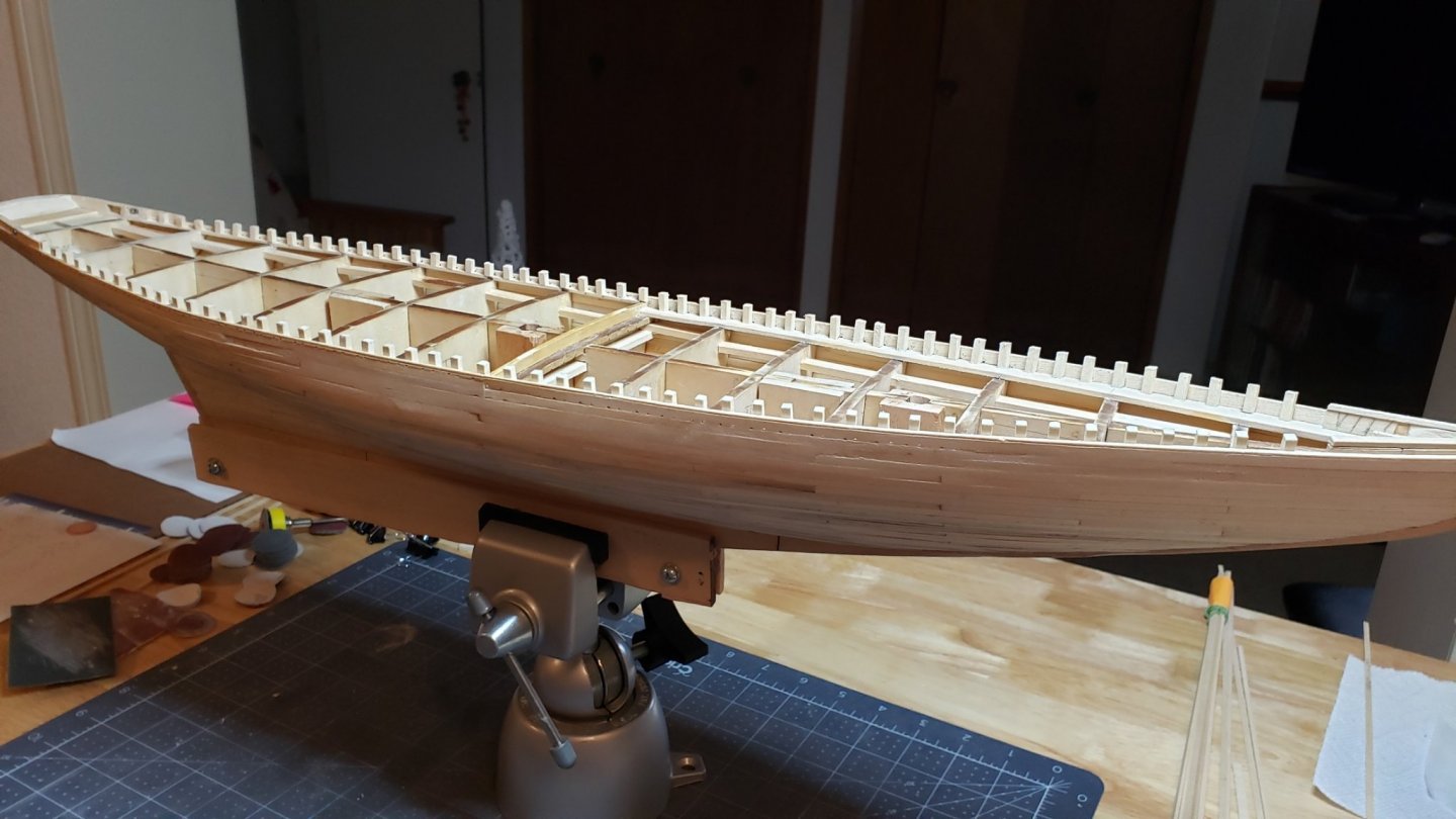
Got back to Blogging today. Some progress has happened. I was not looking forward to the hull sanding. It actually went very well. A pleasant surprise! The weather was warm enough to sit outside so the whole house didn't get dusty. The planking was pretty uneven and had various bumps and dips. After some experimentation I used a foam sanding block and a small solid block. For the tight curves I used an appropriate diameter auto hose wrapped with sandpaper. I started with 100 grit to remove the high spots. Then used a generic, water based, natural color, wood filler from Ace to fill the dips an cracks. As you can see, there's a lot of dips and cracks. I also experimented with using model airplane dope mixed with micro-balloons. That's the white stuff in the picture. I found the dope mixture dried quite hard and was difficult to sand. It did fill small cracks well. This was done twice and then a pass with 220 grit. The hull now looks pretty good. There are still a imperfections and slight dips to fill. One more pass should do it. The next step was installing the waist. The supplied wood was not long enough to run the entire length. I split it at the mooring chocks at the stern and the knighthead at the stem. Then trimming the stanchions which were deliberately cut a bit long. I used this neat little 1" sanding disk with a Dremel. Just have to be careful with the angle of the cut and not nicking the waist. Here's the overview:


-
Hi Bob, The yellow paint will be so prominent that the cove will not be noticed. Retired Guy did a cove that's a bit bigger than scale and it looks really good. But he used a special power saw to cut it. In the end, I don't think it adds much over the simple yellow line when viewed from a distance. John
-
I decided to do some experimentation in the daylight today. I wanted to settle my mind about the cove. The cove shows up nicely close up. Then I took another from a viewing distance of about two feet; The scuppers show nicely - that was worth doing. The cove is almost invisible. The yellow paint line will stand out much more than the actual cove. My conclusion is painting the thin yellow line is better. It's a lot of extra work to make and to maintain the cove during finishing when the it will not be noticeable at viewing distance.
-
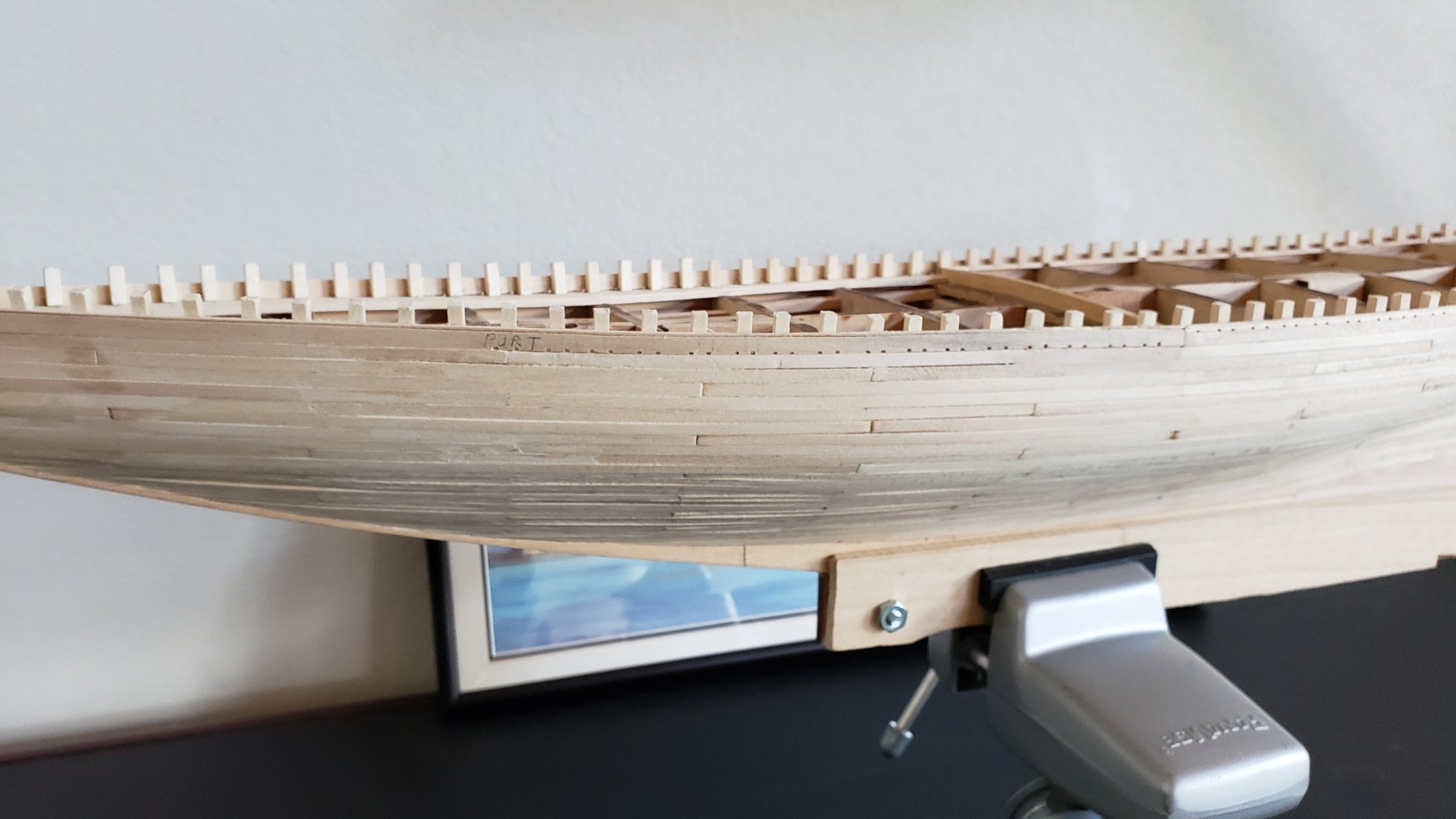
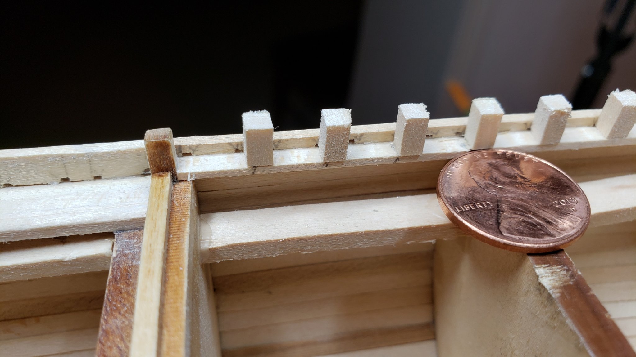
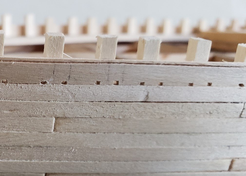
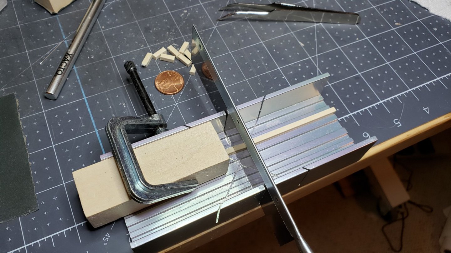
Working on stanchions tonight. Supply run with the wife today. She likes the moral support. Like most here, I found the bulkhead extensions make poor stanchions. They are uneven, too short and not angled quite right. I used them for the first plank above the waterway to set the line of the bulwarks. After gluing the fake stanchions on, I cut the bulkhead extensions off and replaced them with properly made ones. Here's a picture before the bulkhead extension was removed for comparison: Here's my simple jig for cutting stanchions; This was not as uniform as I would have liked. I cut them a touch long and will sand them to the correct height after the waist is installed. The Knighthead was cut to the (incorrect) height of the "A" bulkhead extensions. I added shims to raise the timbers to the correct height. Note the stanchions start to slant outward near the stem. It's necessary to sand a slight bevel on their bottoms. There are 60 of these little things to make. Took a whole day. Here's the finished stanchions;

-
Hi Ron, The whole stern area is a headache. I think it's not very well documented for such a complicated part. I've noticed it's a common problem area in many build logs. For the Model Shipways kit the stern ends up too wide. The laser cut parts match the plans, but people find the as-built stern is often wider. When you get to that part look through the logs. There are two common solutions: 1. Make a new main rail stern piece to fit the actual model. 2. Make cuts to separate the side rails from the center and add appropriate sized spacers. They should provide a stern view detail drawing with actual dimensions at 1:32 scale. The boom buffer support is also shown incorrectly on the plans which show a simple shelf. If you look at the prototype photos its more of a box or perhaps a solid piece. The flanges are not correct on the mooring piece either. On the prototype photos you can see they cover the entire space of the mooring chocks on the inside. I'll probably just paint the area black to simulate the larger flange. It's in a place that is not very noticeable. Thanks for the compliment, John
-
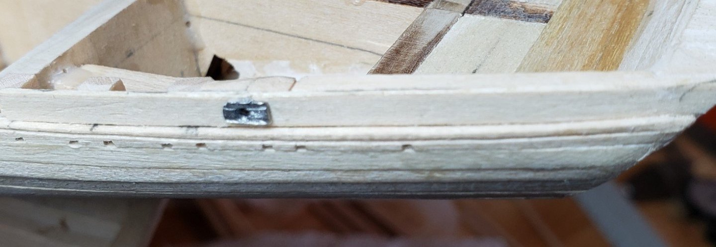
Next were the mooring chocks and ferule. As pointed out on other blogs, this is a less than nice Britannia metal piece. I was able to clean it up fairly well and carefully drilled a hole in it. The piece also had to be shortened so it doesn't stick out the inside of the chocks. I'm still looking for some way to flare this piece. The hole doesn't look right when simply drilled. While the part is not well cast, it should look OK once painted. Oops. Looking more closely at photos of the prototype the flange goes on the inside. It's set into the mooring chocks. Have to tear this out and redo.