HOLIDAY DONATION DRIVE - SUPPORT MSW - DO YOUR PART TO KEEP THIS GREAT FORUM GOING!
×


JohnU
-
Posts
170 -
Joined
-
Last visited
Content Type
Profiles
Forums
Gallery
Events
Everything posted by JohnU
-
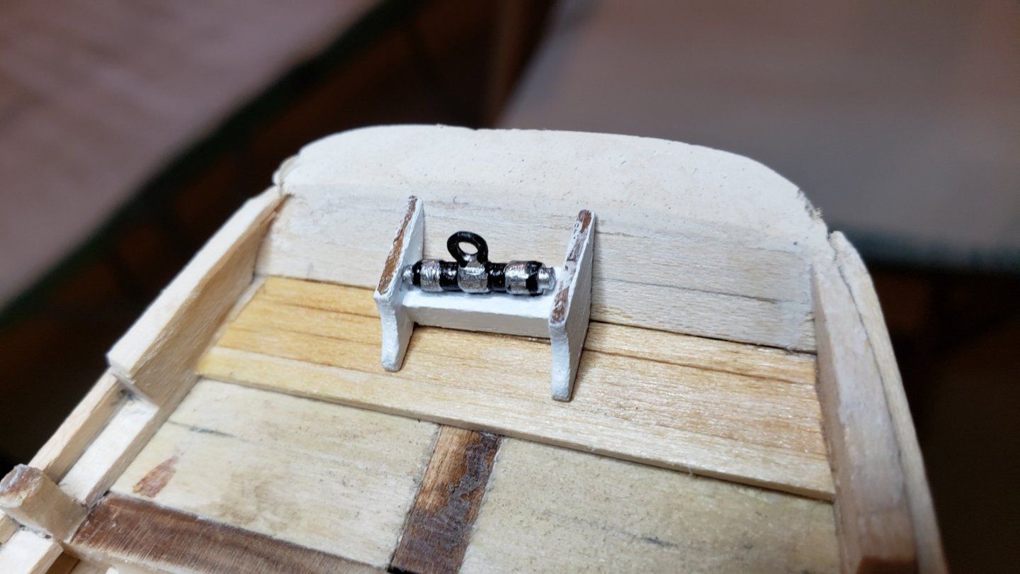
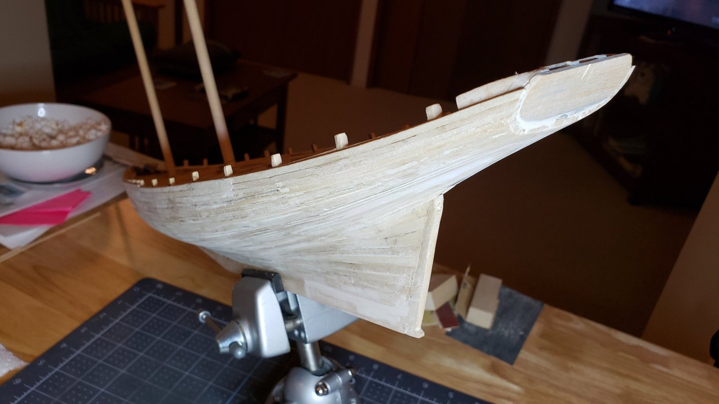
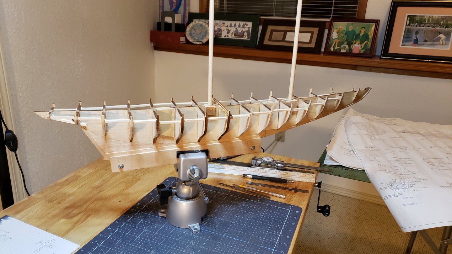
 Did more work on the stern yesterday. Due to my lack of carving skill this is an iterative process. It's a fill, sand, check, fill job. Each iteration gets closer. To get the proper shape of the main rail at the stern I shimmed key points and slopped wood filler on, then placed wax paper, wax side to the filler, over the filler and pressed it into shape using scrap clamped into place to create the correct shape. It turned out pretty close. Still some filling and shaping to do. While I waited for the filler to harden I started on the main boom buffer. The brittania metal buffer is not so nice as "Retired Guys". He created an actual working boom buffer in scale. Be sure to check out his build log. The supplied one cleans up pretty well and is mostly hidden but lacks some detail. The supplied plans have great detail on this piece for those with a mini-lath.
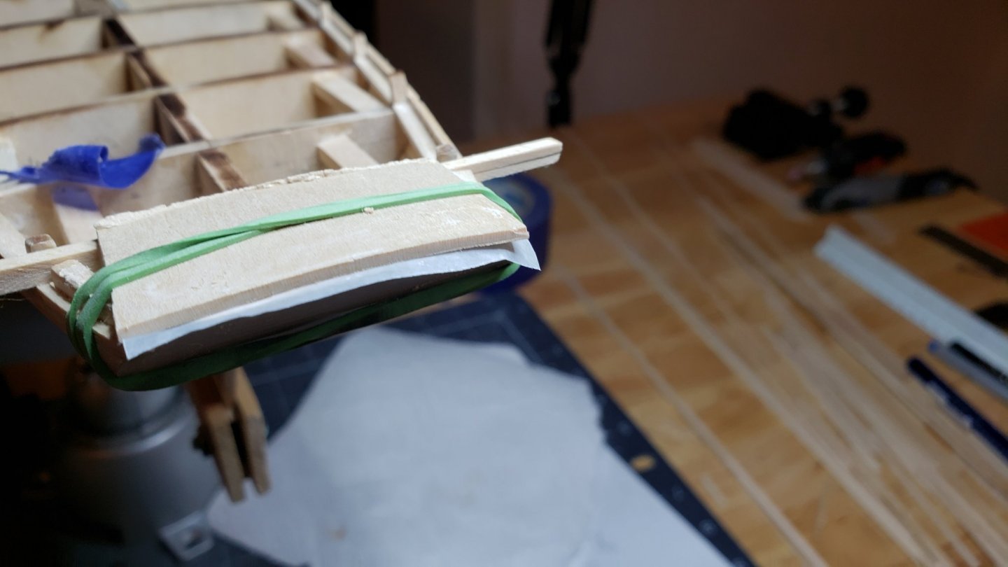
-
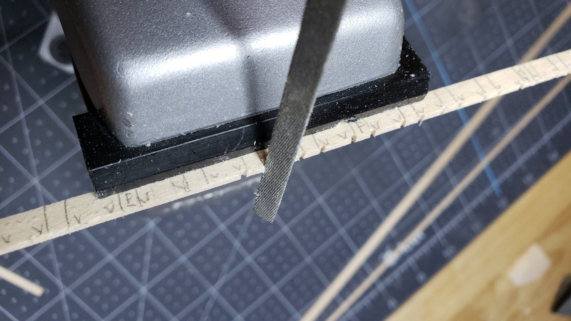
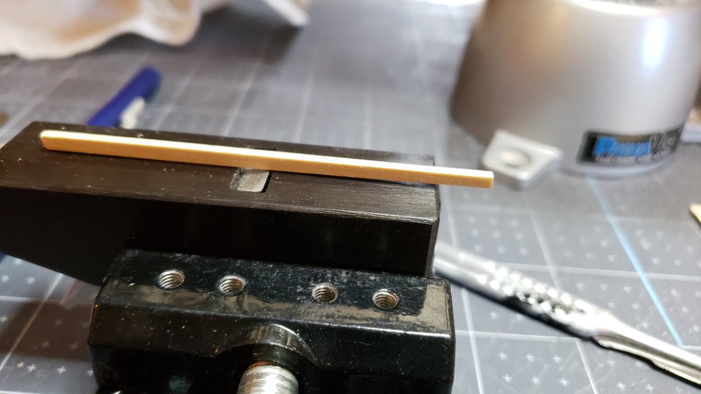
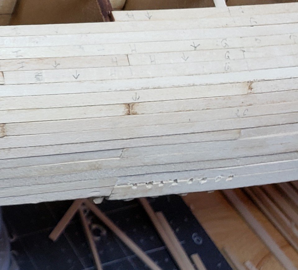
Today, I gave some thought to the cove below the waist. Looking at pictures of the prototype it adds a nice detail to the ship. It would be even more pronounced in color(yellow) against the black of the hull. I didn't see much about it in most build logs. I made a simple tool to create the cove and experimented. The tool is a block with the backside of an old scalpel blade. The idea is to press the shape into the basswood rather than cut or scrape. The thickness of the blade(could be any rounded piece of metal) determines the width of the cove and the thickness of the shims on the block determine the offset from the edge of the plank. The depth can be controlled by how far the blade extends beyond the block. In practice the depth is easily controlled by hand pressure and the setting of the blade was not too important. Below is a picture of the result: This does a pretty nice job but requires a steady hand. With parts this small it's easy to slip. It wouldn't be too hard to make a jig that you push the plank through for a more controlled impression. In the end, I decided it wasn't worth the difficulty. It still has to be masked and painted. When the ship is finished the detail would probably not be noticeable at a normal viewing distance. The grove necessitates a constant cleaning out to keep it visible when filling and painting. It will be there but I'm not going to make a great deal of effort to keep it cleaned out. I suppose it'll serve as a nice guide for masking during painting.
.thumb.jpg.83ed33dffdb6d9467d4a90723214e4a0.jpg)
.jpg.ba0c72474cdf6322b7a982fcd9fc74fc.jpg)
-
Hi Bob, I've been using some it it for shims as well. I like the idea of doing the roofs with it. They should look very nice when finished.
-
Thanks Richard. I have a set and they are handy.
-
OK, Thanks. That's an odd way to do it though.
-
Hi Ryland, Thanks for the nice welcome. The techniques come by way of the very helpful forums on this and other web sites. Also by reading the great build logs. Unfortunately, it's not all technique. There is a great deal of skill involved. As you say, that's gained by doing. Some things you can study all the techniques and buy every tool but get a crappy job until investing time in practice. Like drywall or soldering copper pipe fittings. My step-son is learning this for the first time as he paints his apartment. I see you are a moderator. Perhaps you can give me some pointers in using this site. I don't see how to reply directly to comments and am simply adding more replies to answer commenters. I see in other build logs where the reply is direct and the previous comments are quoted. Would you mind explaining how that's done? John
-
Hi GuntherMT, Thanks for the help. I was trying to do this with a mini miter box that had appropriate size slots. I couldn't get a consistent size out of it. Perhaps the miter box slot was just not snug enough against the saw. I couldn't even get truly square ends. I'll give your suggestion a try. It's a painted model so I can use filler. Sadly the rough planking means lots of sanding. Interestingly, Model Shipways supplies walnut in a thickness for doing a double plank job; even though they don't say that in the ads. John
-
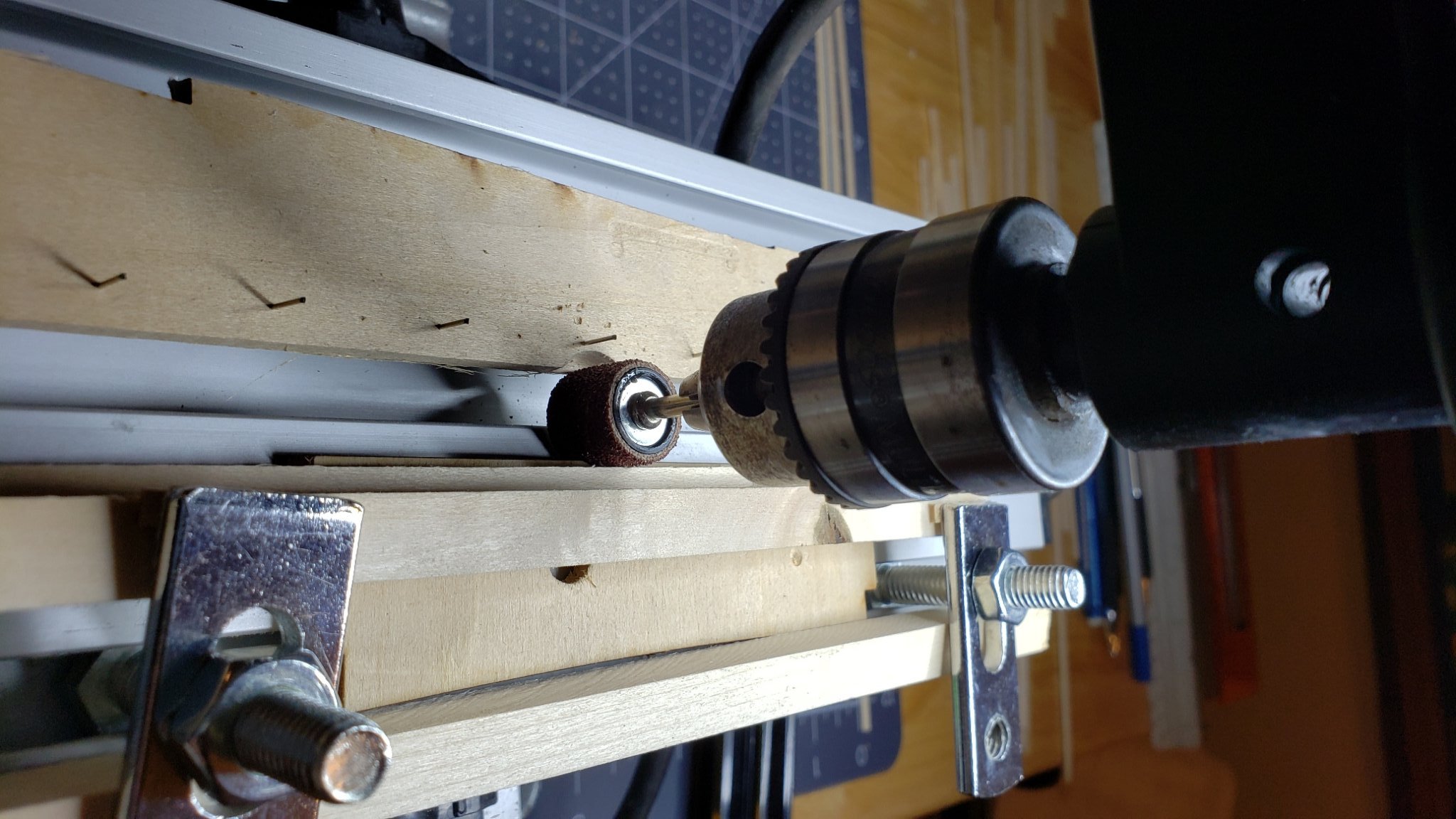
I debated about adding the scuppers. They were so small I thought the detail might not be visible on the finished model. After looking at other build logs I decided they were worthwhile. It's a nice detail if done properly. By having them painted the same color as the waterway they stand out nicely against the black. I'm still undecided about the cove just below the waist. On the prototype it's quite noticeable and the color is yellow. Some people just paint a yellow stripe and others create the actual cove. The problem is how to make such a small detail in a uniform way. Need to make a tool to get this right. The scuppers turned out pretty good except the plank leaves a noticeable line that needs filling. Of course filling will also close the scuppers and they will need to be cleaned out later. Just have to deal with that when the time comes to sand and paint. There was no wood supplied with the kit the right height for the quarterdeck scupper plank. I made a jig using a drill press and sanding drum. The fence is positioned to the finished size of the plank from the drum. Then it's just a matter of carefully feeding the plank through. The actual scuppers turned out to be the easiest part, but tedious. I had a file the thickness of the scupper width. It just took a bit of file/check/file to cut them. This makes a really neat slot with square corners. There are a LOT of those little things! Here's the finished result. Please ignore the rough planking job. This was my first attempt at planking and the last part is much better than the first part.


-
Hi Bob, Thanks for the info. You must have a very steady hand to do that scrollwork! I was thinking I might try decals for the scrollwork. I could scan the drawing and print it on the decal paper. The prototype does appear to have depth though. I read one log that used a 3-D printer to make it. I looked through your log. Wish I had done that before I did the scuppers. That was a great way to do the layout. John
-
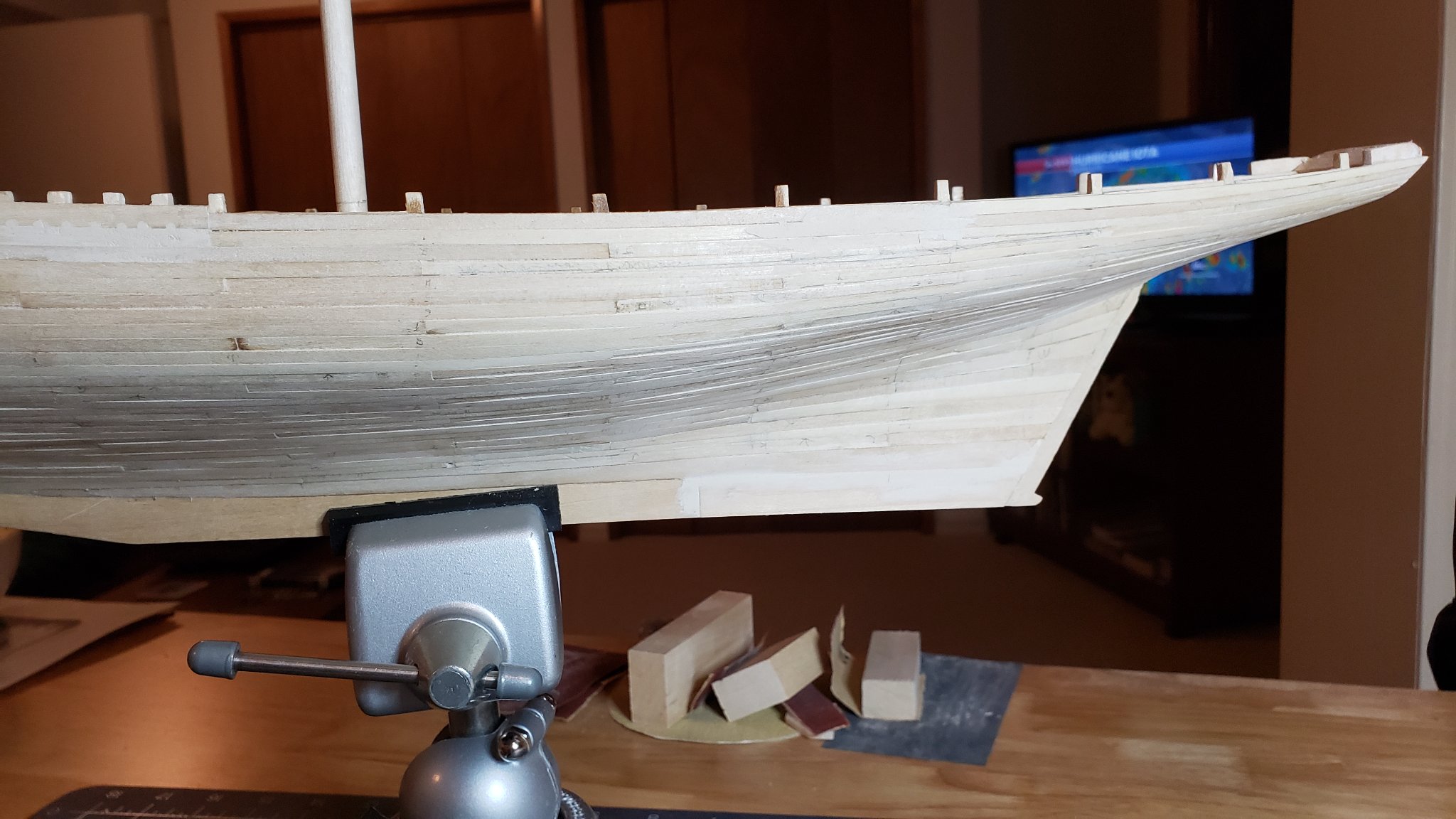
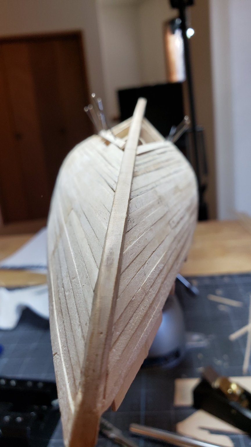
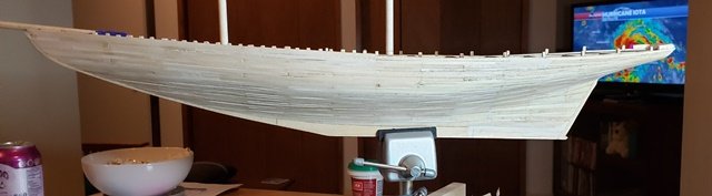
Pics of finished hull planking:


-
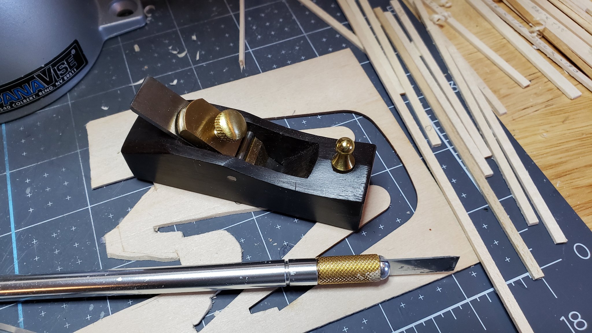
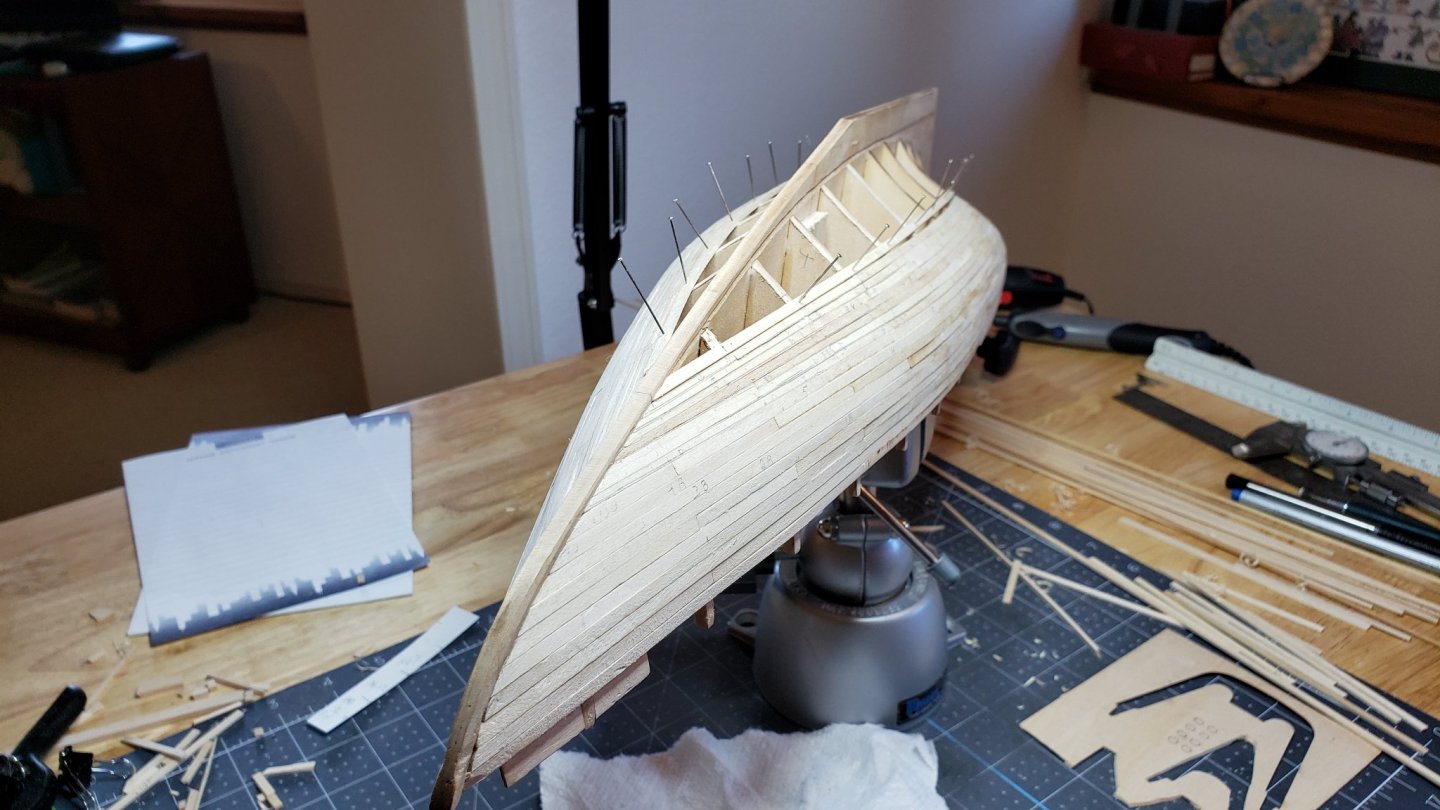
And now; Drum Roll; My first attempt at planking. The make-or-break of a POB build. Now that I have the hull planked, I'm pretty pleased that it came out as well as it did. After all, this is a first attempt. There will be much sanding and some mistakes were made. It's a painted model so the mistakes will be hidden. Two observations: The prototype was not a perfectly smooth hull. In pictures of the original you can see the planks. The planks were wider than the Model Shipways plans indicate. Plan Problems: The way the planks lay on the counter and transistion to the keel was not clear from the plan and the manual. It took some experimentation to figure it out. The stern post in the plan is a different length than the laser cut implementation by about 1/2 inch. thus there are 12 planks shown from the top of the post to the Garboard but only eight fit on the actual model. Unfortunately, I did not realize this before planking and I went with the provided plan. This is not a serious problem in a painted model. I will remember not to make the hull completely smooth though. Some slight plank shapes should show through the paint. Looking closely at the model after planking I can see a dramatic improvement as the job progresses. I was experimenting at the beginning and learning technique. By the time the last planks were laid they were looking uniform and well butted. Throughout I used that iron of my wife's. She doesn't iron anyway. It worked very well for bending. High cotton setting and a little bucket of water next to it. I simple dipped a plank in the water and held it against the iron. The water turned to steam and penetrated the wood. There was little wetting and my planks were dry by the time the bend was done. After the first steaming I could soften the wood with heat only. This kept the planks dry. I could even get a bit of lateral bending out of the basswood. Another tool that was essential was a miniature plane. This was a nifty, nicely made tool on sale for $4.75 with Amazon Prime. To shape planks I clamped it upside down in a relatively heavy vice. I could then mark the plank with it's shape and draw it across the blade of the plane. It was even possible to calibrate it to .005" per cut. That way I knew just how much to cut. With a little practice I could get nicely shaped planks quite easily. It took considerable experimentation and research to get the hang of using battens and measuring with tick strips. The plan also was difficult to read the proper taper of planks from. In the end I simply made up the tapers using my own measurements taken with tick strips and calipers. I took plenty of breaks to avoid getting sloppy. As per recommendations on other planking practicums, I tried to bend my planks to lay perfectly in place before gluing. The PVA glue worked very well as a result and I needed to do very little clamping, and none for most planks. The PVA would set in about a minute. 30 seconds in thin coats. Just enough time to get the plank positioned correctly. For that short a time all I needed was my fingers to hold planks. I could use one hand to hold the plank and the other to wipe excess glue. I put a small drop of glue on each bulkhead and a bead on the mating side of the plank. After putting the bead on I ran my finger down the side to spread the glue in a thin coat. Set up time was just right. The planking appears to be very solid and strong. Below are in-process pictures: Ready to close! Looks really cool on the inside too...


-
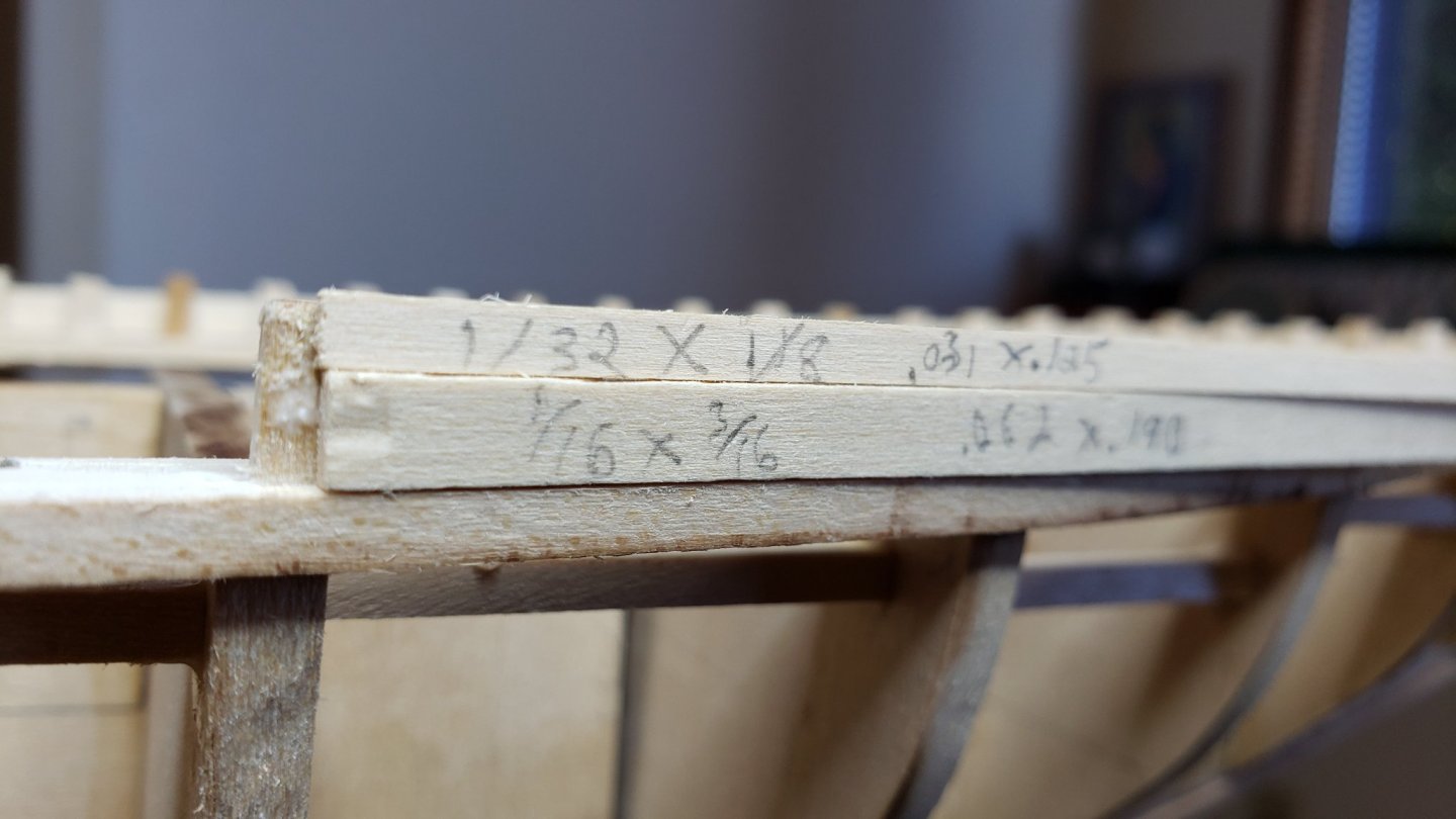
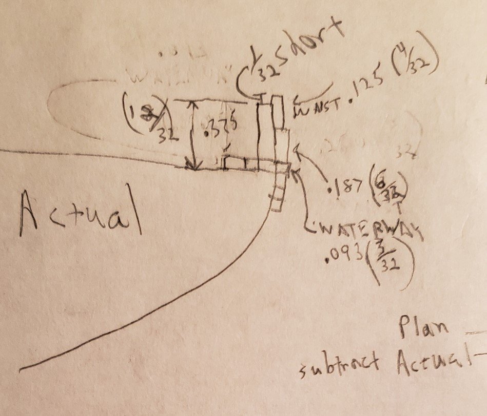
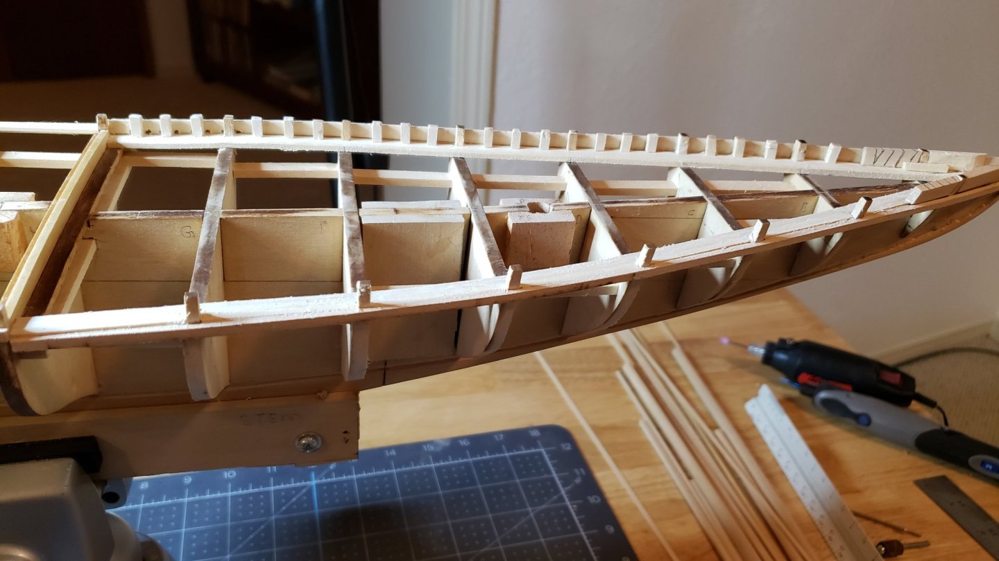
The waterways are important to get right as they set the upper run of planking. The manual and plans have really good detail and examples of the waterways and an enlarged diagram of their installation. This went well except at the great beam where the bulkhead was slanted a tiny bit fore-aft. Some experimentation indicated this was not going to be noticeable once the planking and waist were installed. Oddly there was an extra piece for the great beam in the cutouts. At this time the knightheads were installed. At this point I discovered an inaccuracy in the kit. The bulkhead posts are all short by 1/32 inch. careful measurement confirmed the posts are 1/32 short compared to the plan. ALL the posts. There must be some systematic error in the laser cut programming. Two ways to fix this. Add a 1/32 strip under the main rail or replace the posts with the correct height. Either will work as the difference would be hidden by the waist and main rail. Still, it's extra work and an annoyance. I'll save this for later. At this point I got impatient and decided to try making the scuppers with a handheld Dremel tool. Lesson learned: Bad idea. Now just a mess to clean up and redo. Another "tackle this later" item. I also experimented with cutting and installing stantions. This did not go too well either. I had trouble getting a uniform height which will be needed to set the main rail correctly. I experimented with my usual methods of getting uniform cuts but these are too tiny for those. I'll have to figure out something new. Suggestions are welcome. Looks pretty though.
-
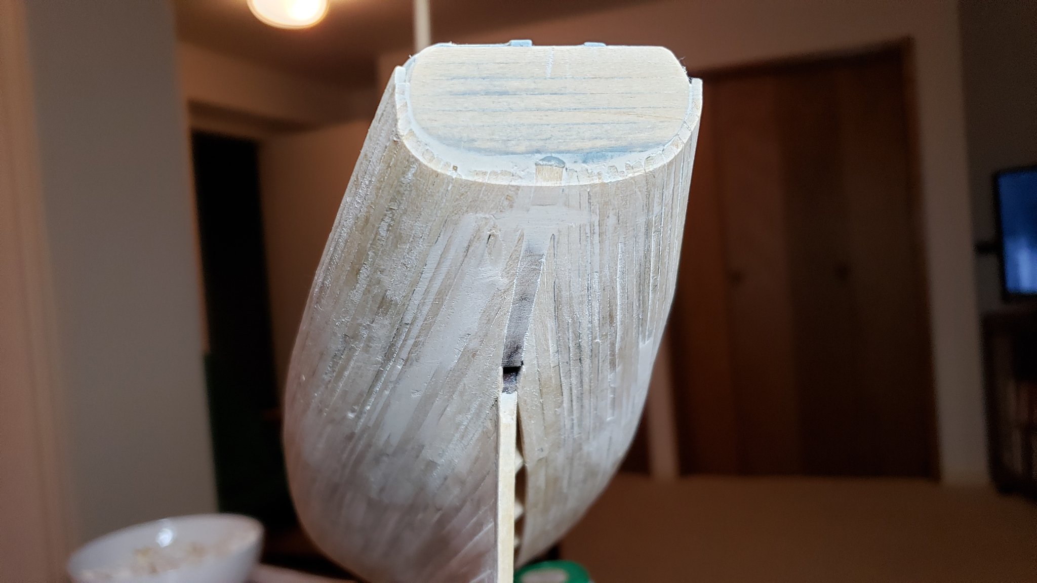
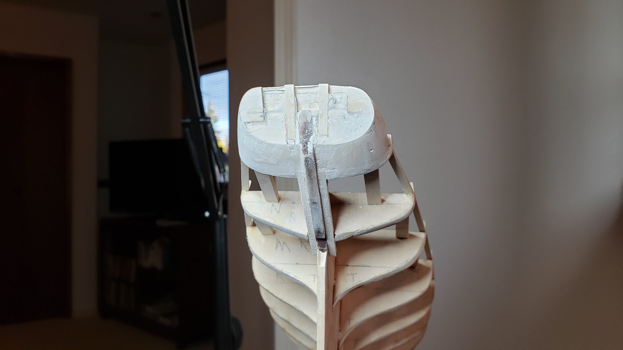
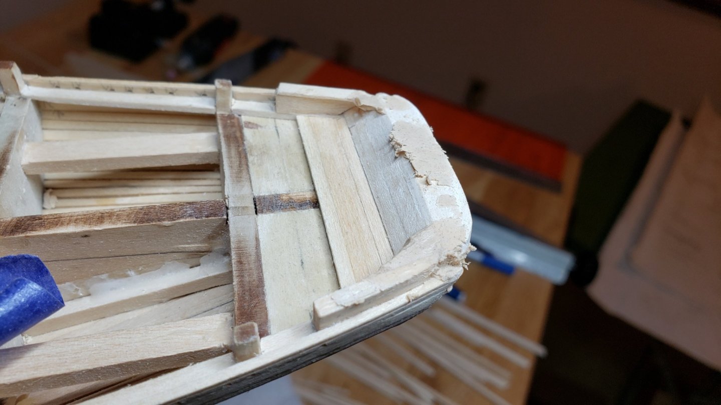
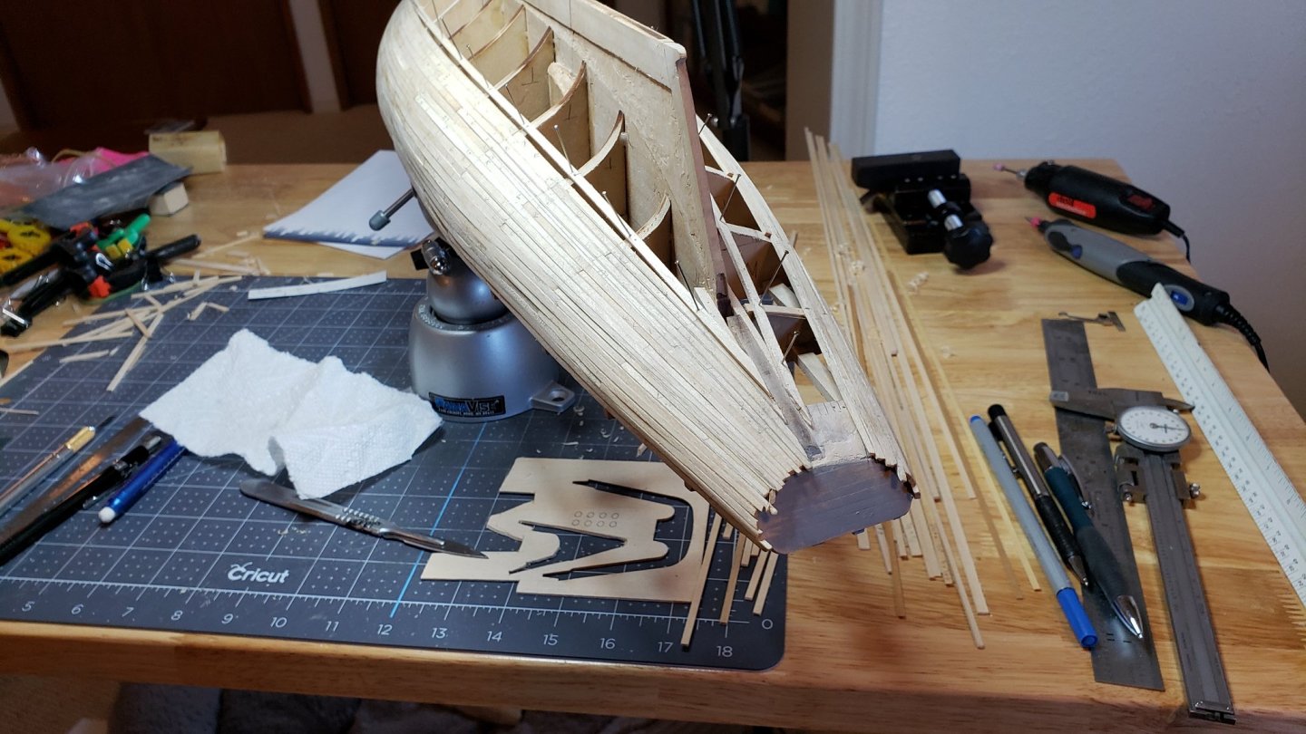
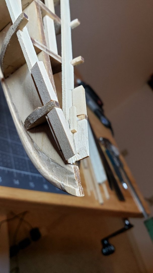
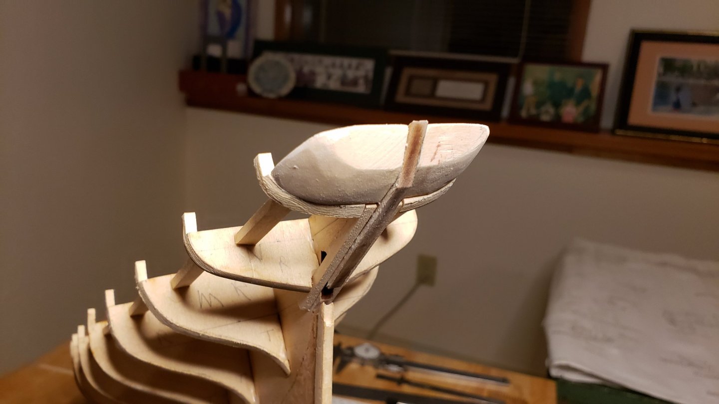
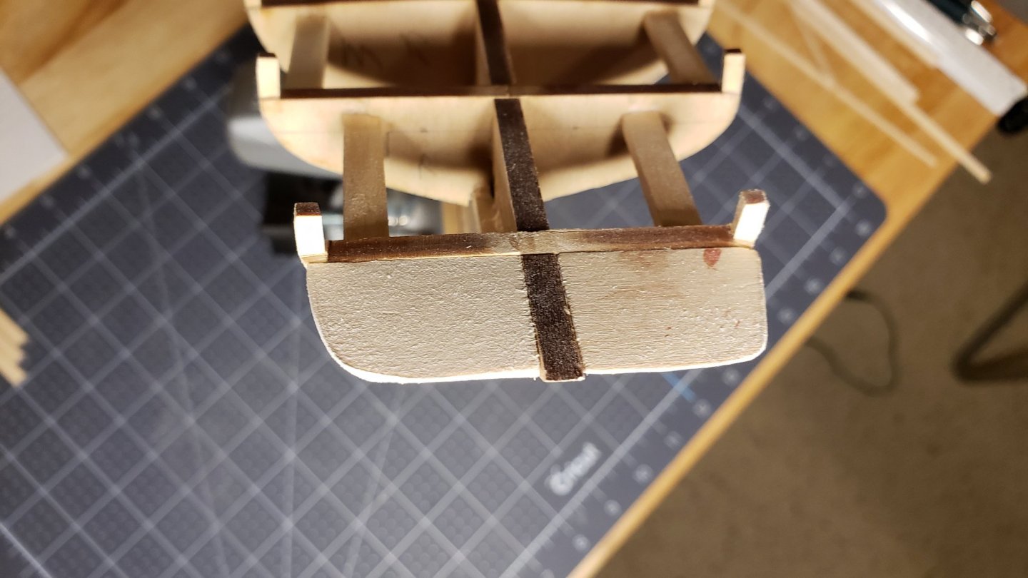
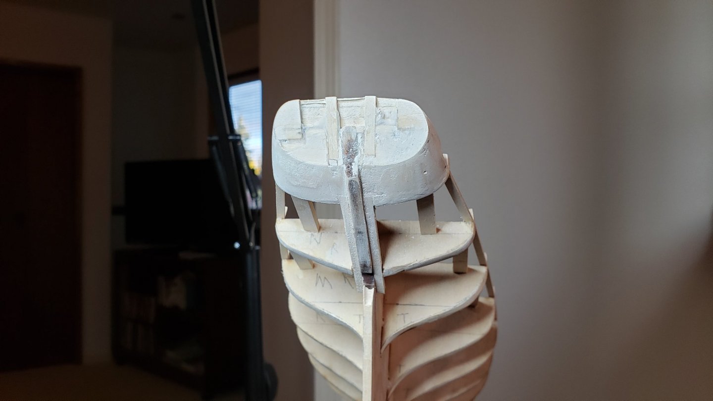
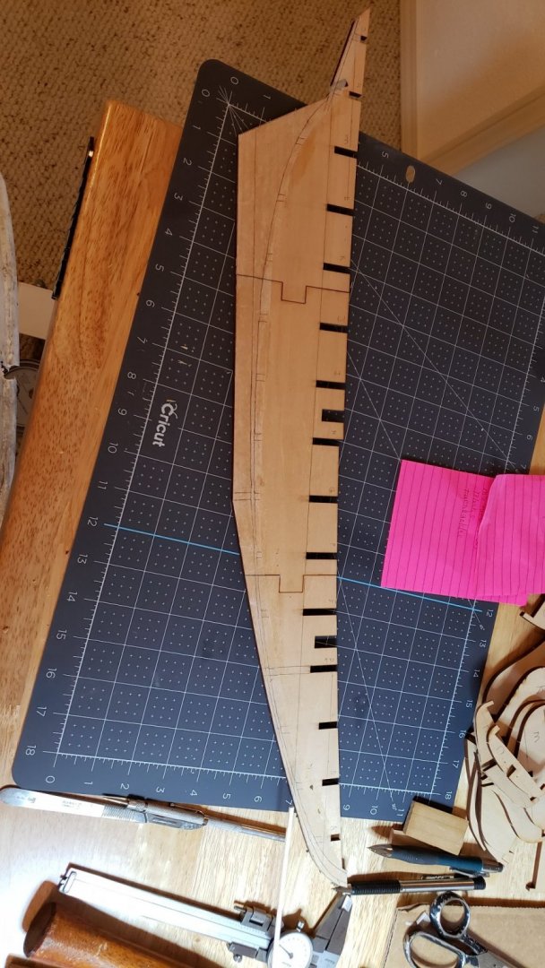
Next the stern blocks. An area of difficulty for me as my carving skills are abysmal. The plans do not give a good account of the stern. There are several exemplar drawings which are only orthogonal. Some dimensions and a guide for the angle of the counter would be helpful. As it is, it's pretty much up to the old eyeball. A tiny piece of angled keel is all there is to go by for the angle. The plans show small inserts in the stern blocks for the counter timbers, but they are not sufficient to hold these pieces and the angle is not shown. This turned out be be an iterative process. I created some rough blocks that fit against the last bulkhead which did not give the proper tapered shape and provided an uneven curve. The counter was built up and shaped with multiple passes of wood filler and sanding until the side pieces and timbers could be set. Then lots more wood filler and sanding to shape until it was sufficiently accurate to plank inside and out. Still pretty crude, but getting there. Good enough to plank at this point. Still some shaping to go.
-
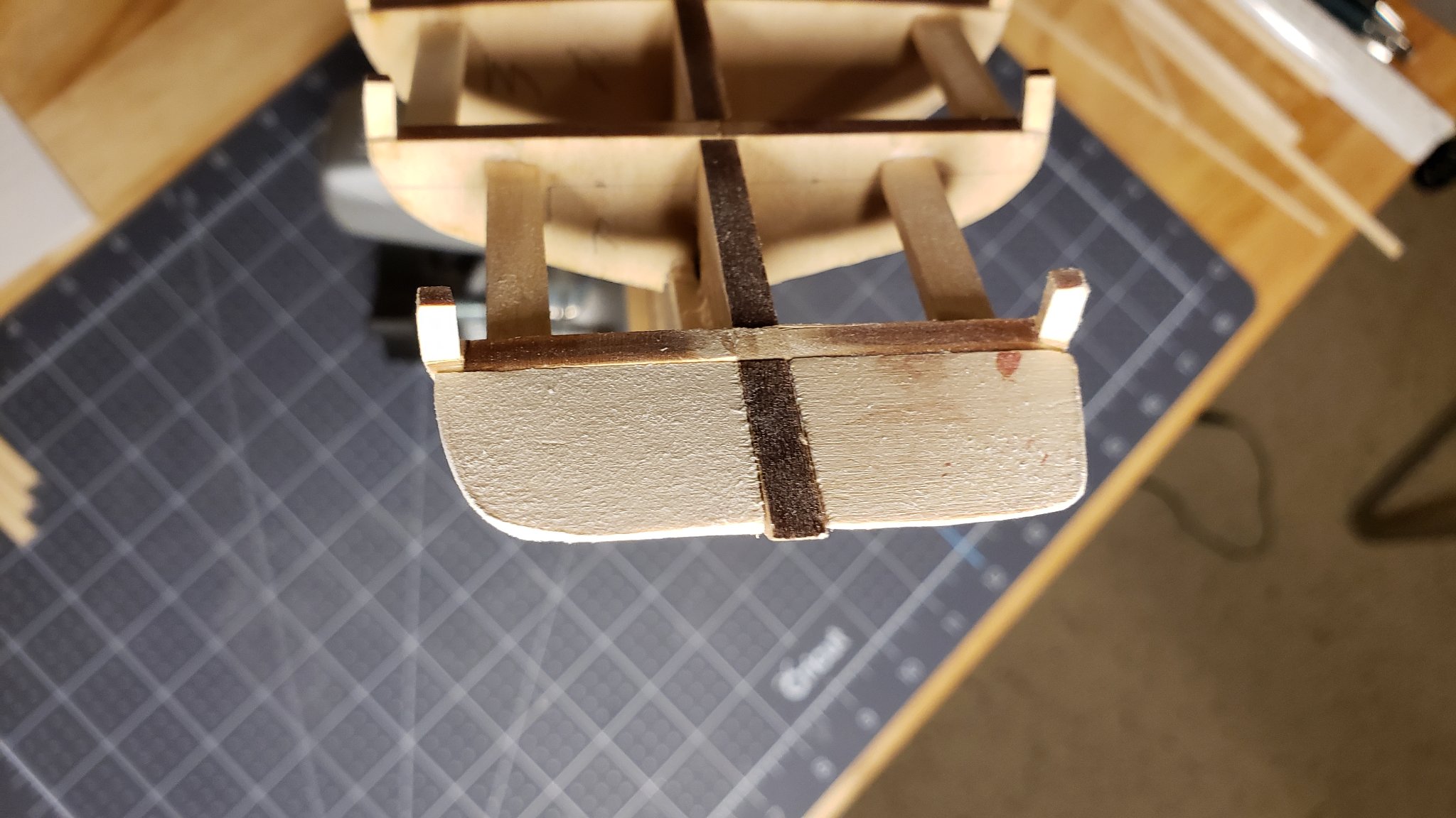
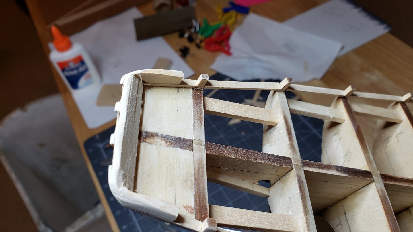
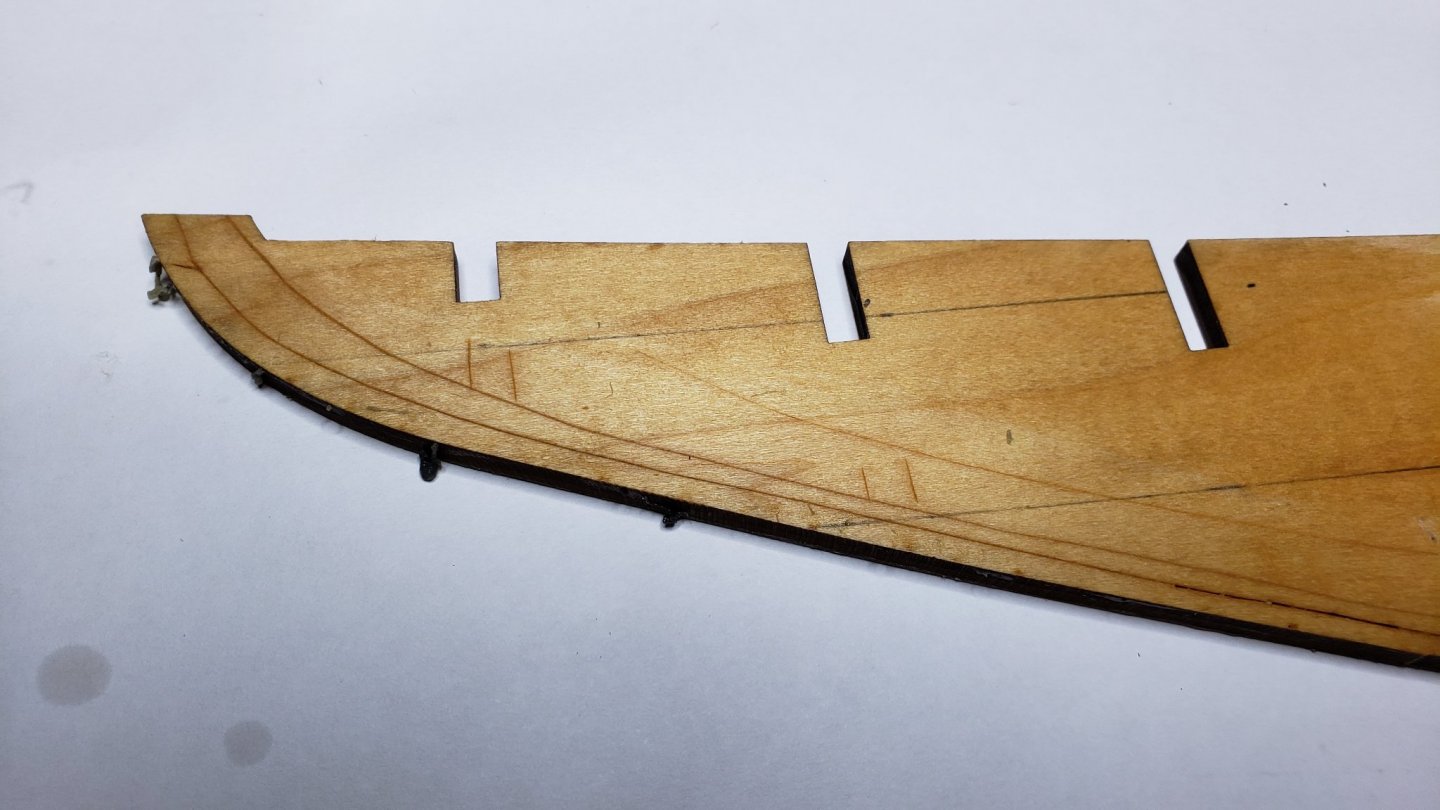
The counter area is not well explained. Neither the plan nor the manual had a good explanation or diagram. However, between the two I was able to figure it out correctly. After the bulkheads are installed notches are cut for the "horn" timbers. These are set into and flush against the last two bulkheads from the bottom. This leaves the keel out the depth of the hull planks which butt against the keel in this area and glue to the horn timbers.
-
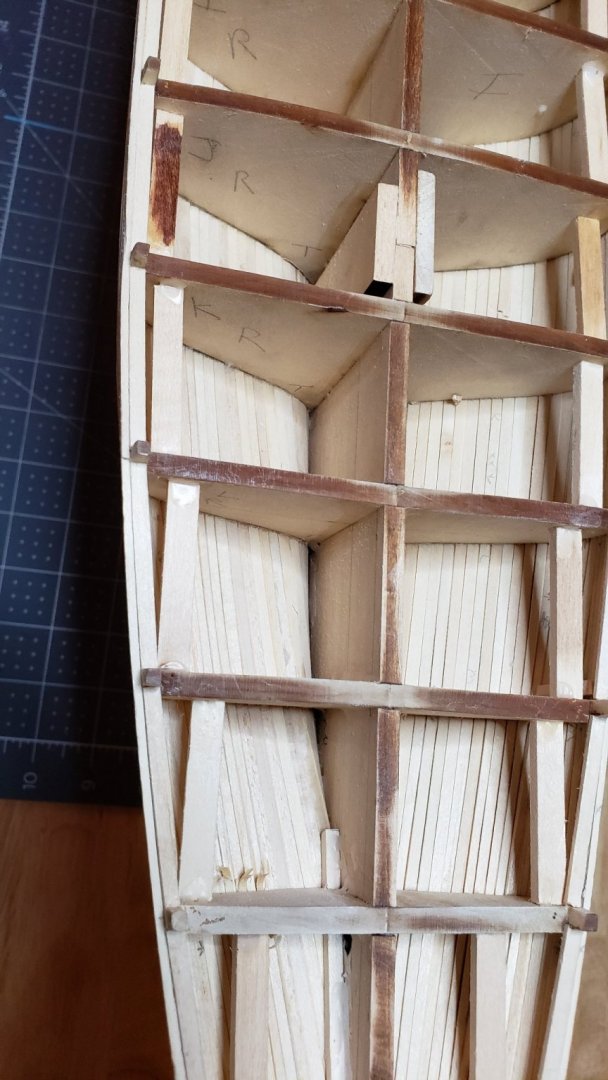
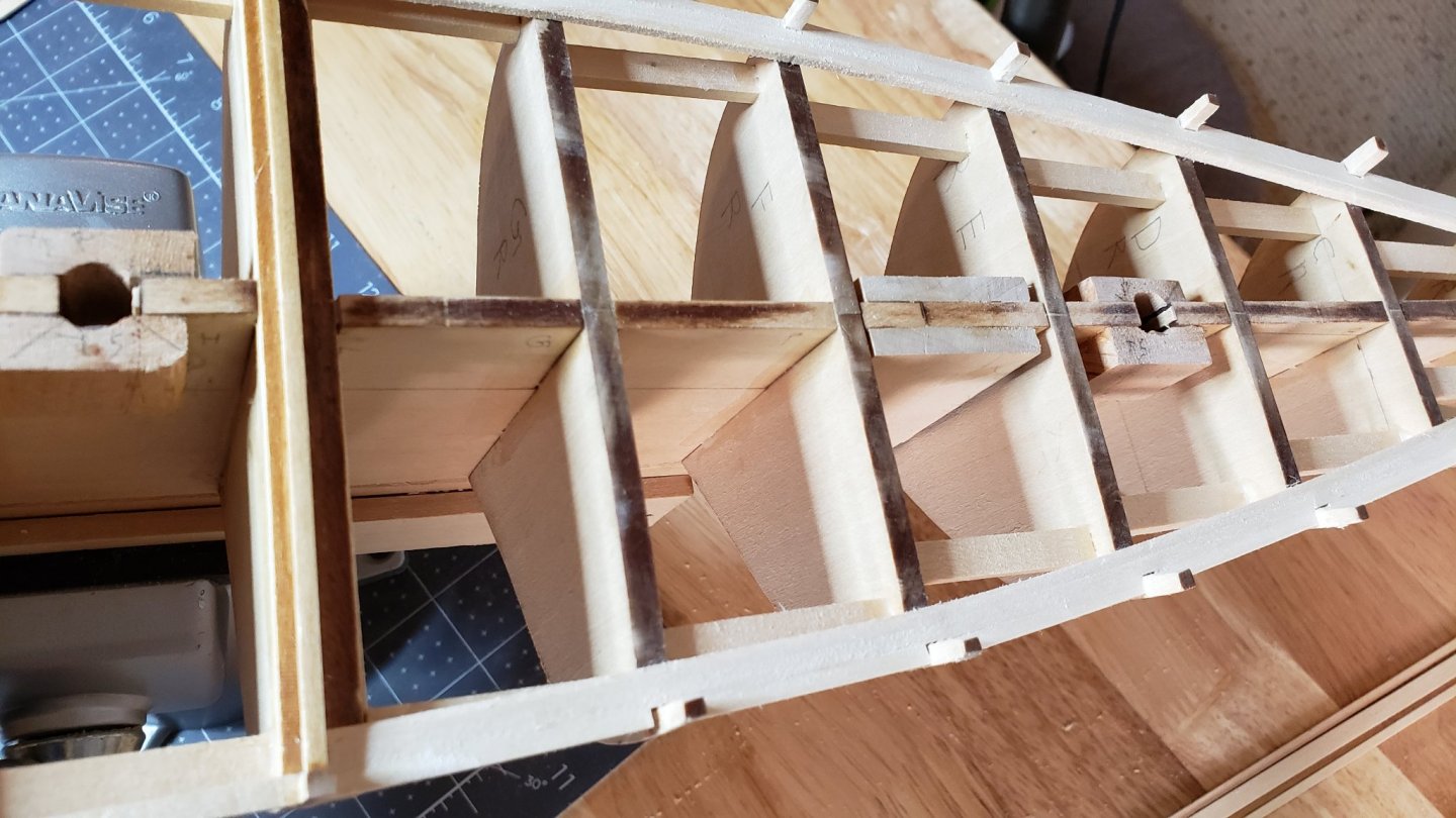
The wood the bulkheads were in was slightly curved. I found that steaming with a household iron worked pretty well for flattening. I don't think my wife realized what I was doing with her iron. The iron was set on the high cotton setting. Iron the bulkhead until hot and let them dry on a flat surface with a weight on top. Next the bulkheads were faired. The bulkheads and their tapers are shown on the plans individually. I found the tapers to be accurate. Again the taper lines need to be transferred to each bulkhead and the bulkheads carved before assembly. Be sure you taper the correct side of each bulkhead. I marked them with the correct side and the bulkhead letter to be sure. A Dremel with a sanding drum worked pretty well here. Installing the bulkheads is straightforward but finicky. They must be aligned square to the keel and vertically. Mine were nicely squared lengthwise using square blocks and clamps, but one had the fore-aft slant off a bit . In retrospect I should have shimmed them tight in the slots which would have prevented this. The laser cut fit is pretty loose. To ensure they were correctly spaced I cut spacers for insertion between bulkheads at their outer end. This also adds strength and ensures any residual warpage is removed. As recommended, do both side spaces at the same time for each bulkhead to avoid the dreaded "Banana" warp. Keep an eye on the tops. They must be flush with the keel to accommodate the deck.
-
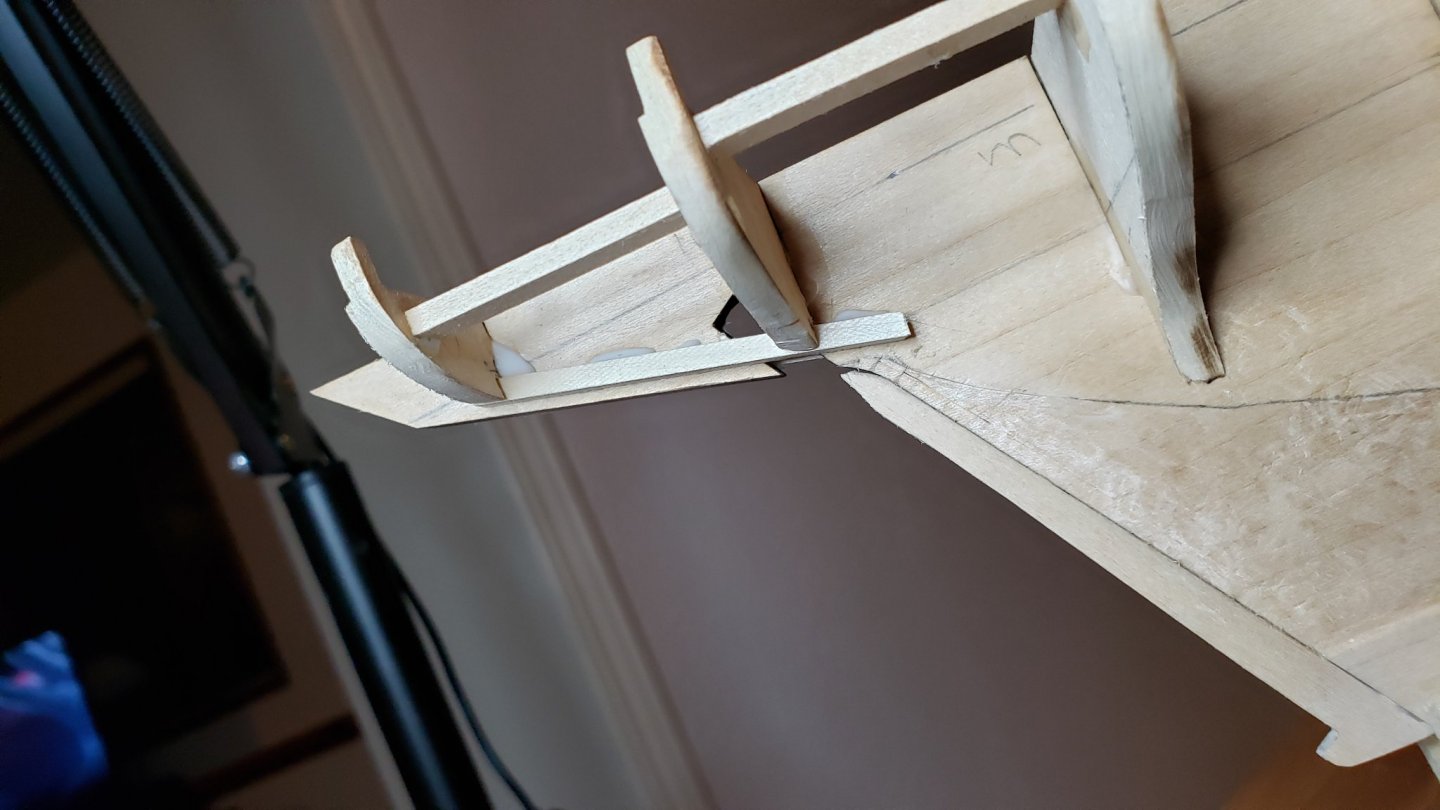
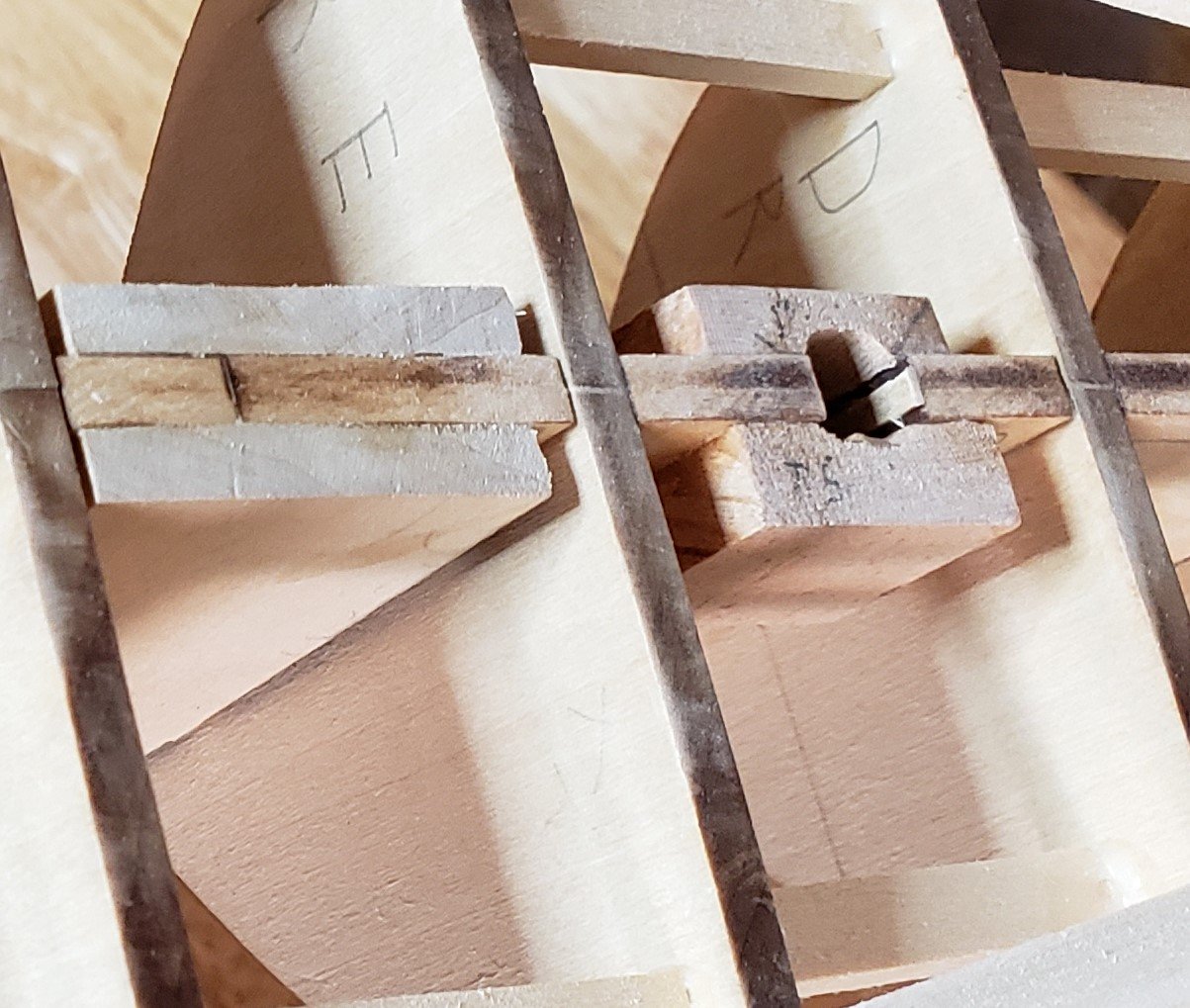
Of the two methods of creating the mast sockets I chose to use two half blocks around the preformed slots. As pointed out in the plans this method allows the mast to be removed later if needed. It also allows for shims to be glued in the hole to adjust the mast alignment. A block the depth of the mast slot and three times the width of the false keel was cut. The block has a hole drilled that provides a snug fit for the mast. Then a section is cut from the block the thickness of the false keel. The two halves are glued over the mast slot using the mast dowel to keep everything aligned. Also note the keel seams have reinforcing blocks glued in place. This adds strength and discourages warping of the keel. Don't forget to sand these pieces flush with the top of the keel. The Model Shipways kit does not include a sub-deck as the Billings Boats kit does. The deck is laid directly on the bulkheads.
-
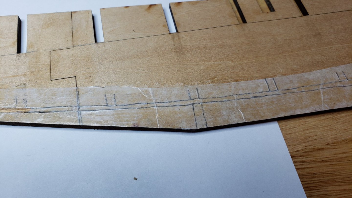
The next problem was bearding. The plans have good details of the bearding. The problem was to transfer the lines from the plans to the wood. I chose to do this using the wax paper as it was fairly rigid, translucent and comes in long rolls. Tracing paper also works but is often flimsy. Trace the bearding lines and alignment lines from the plans, then use contact cement to attach the wax paper to the wood. From here, you can cut the bearding lines through the paper. I chose to mark the lines with a scalpel and remove the wax paper. This provided a nice clean line and no paper to get in the way while cutting the bearding. This went well using a chisel blade Xacto knife except for the large area of bearding near the stern. I could not get the shallow angle required because the handle of the chisel interfered. This area ended up being a little chewed up. I was able to smooth this enough it would not affect the planking. A chisel with an angled handle would be helpful here.

-
First step is to assemble the keel. This is when you first get an idea of the real size of the project. Bluenose is a very satisfying size. Another reason to pick this kit. Having three sections is not ideal. Sections are carefully fitted and glued. The assembly is placed on a flat surface with wax paper. Wax side toward the wood. Another layer of wax paper and weights on top. After drying there is a nice, straight keel. Double check for flatness. It's not too late at this point to make corrections.
-
While waiting for the kit to arrive there were lists of small parts and tools to acquire as part of upping the skill level. A craftsman needs the right tools to do a good job. No more hacking away with the wrong tool! After all, my wife is always telling me I shouldn't be so tight. The build logs and forums on MSW were very helpful with sources and suggestions. After reading the tools and tips forum I decided to go with PVA glue. Ordinary Elmers Glue-All works well. It's strong and has a convenient working time. I experimented with using both PVA and CA. CA had been frustrating to use on my Cutty Sark. I had inconsistent working times. I also find the CA tends be absorbed quickly in wood and causes problems with discoloration. The kit arrived after a week. I spent some time organizing parts and separating and marking wood. The plans are generally nice. There are multiple views and lots of detail drawings. Some of the detail drawings are not to the same scale. Some are general representations. Be careful! One thing I did not like about the plans is details are not always organized with construction steps they apply to. That led to a lot of flipping sheets back and forth. Overall I'm happy. The manual is, as noted in MSW blogs, rather lacking in detail. I was able to supplement the manual with how-tos and info in forums. It does have key steps outlined. I ordered the paint set recommended for Bluenose from Model Expo. I later read a post complaining about the airbrush compatibility of Model Expo paints. That was only in one blog. Hopefully my experience will not be the same. I looked into getting a practicum. After reading the MSW forums I decided against getting one. There appears to be enough info and build logs that it would not be that useful. I've bookmarked key topics for quick reference. I think I will purchase at least some of the deadeyes from Syren as recommended in many build logs. In particular the heart shaped upper deadeyes for Bluenose are not provided as discrete parts. They are laser cutouts in basswood that need to be drilled and will not match the rest of the pulleys and deadeyes. There are lots of small parts and brass wire and strip. The winch machinery near the bow is provided in cast metal. These are somewhat crude and will need quite a bit of finishing. I see that some bloggers here have made their own metal parts and done a beautiful job. That requires a lath and milling machine. I think I will try salvaging the provided ones before investing in those tools. As pointed out elsewhere, the provide flag is not correct for the era of Bluenose. Also there are no decals for the lettering or decorations. I'm open to suggestions here. I've not seen an ideal solution in the build logs yet.
-
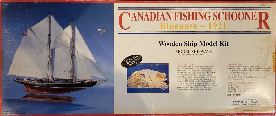
Greetings MSW users. While researching my project I've found MSW to be a wonderful resource. I especially appreciate the friendly and encouraging atmosphere. No build is too small or question too dumb. All are treated respectfully. So unlike much of our world today. I began modeling while in elementary school and continued through secondary school. Mostly cars and airplanes. Simple plastic models and a few wooden airplanes. The hobby taught me about tools, patience and an appreciation for detail. These skills translated well into my later career. I drifted away from the hobby during college and many years of working. After retirement I began to think about building wooden ship models. Something I had always wanted to do. For my first project I bought a solid hull Cutty Sark model by Scientific Models on Ebay. This 1:200 model was about the size of a plastic Cutty Sark I had built during secondary school. While it turned out OK for a first attempt, It was not large enough to do complete rigging. Only the standing rigging and sheets were practical at that scale. At least for my limited skills. Many fittings and details were only approximate representations. The hull had been started and there were a few parts missing when I obtained the kit. Why Bluenose? I was casting about for an interesting but not too complicated POB kit to challenge me and build skills without being overwhelmed to the point of giving up. My wife was pushing for a fairly large sloop rigged boat to become part of our decor. I picked Bluenose for the beautiful and sensuous lines. It also had interesting fittings and rigging, but was not so complicated as a man-of-war or square rigged schooner. The history of the ship was intriguing. Many research materials and build logs are available. Plus my wife found it acceptable. I studied build logs and researched model kits. The three most popular Bluenose kits were Artisana Latina, Billings Boats and Model Shipways. Artisana appears to be the least accurate. Photos and comments in general were not very favorable. The Billings is very popular and it has some construction advantages. However the build logs complain about inaccuracies. Model Shipways kit appeared the most accurate. I was also impressed they allowed for mistakes by including extra wood. I did find at least one inaccuracy in the plans as will be noted later. None had highly rated instructions or plans. At this skill level that shouldn't be a problem though.


.jpg.8a1392af5be4b480be4d76b31c42c6fb.jpg)