
JohnU
-
Posts
170 -
Joined
-
Last visited
Content Type
Profiles
Forums
Gallery
Events
Everything posted by JohnU
-
 Hi Richard, I have one other of a guy climbing the shrouds. It's not very good. It was cast in that cheap metal and doesn't hold detail well. I believe it's 1:48 so could be a short guy. I was debating whether to leave them grey or add paint. The thought is a sort of ghost effect where they would not be part of the model but give it scale. Then focus is on the model detail, not the crew. But the crew can be considered a part of the model for realism. I may try it one way and if I don't like it, the other. On another topic; I was out to dinner with my wife and the place had a model of Flying Cloud. About 3.5 foot tall. The ship was rather crude but the rigging and sails were amazing. Starting to look forward to doing rigging! Unfortunately, I didn't think to take a picture. Thanks for your help, John
 -
I received the ModelU figures. Here's a link:
-
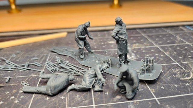
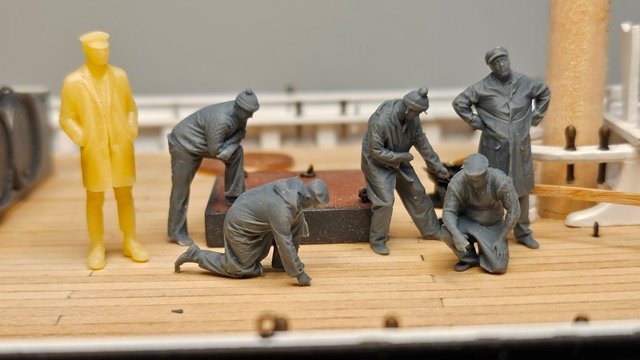
Planning ahead, I want to have some figures on the deck to give the model human scale. Without that a model could be 200 feet or 400 feet. I had a discussion with Retired Guy who suggested Vanguard Models where he obtained his figures. Unfortunately Vanguard Models no longer carries the fisherman crew set. He suggested looking at MODELU. I purchased a set of ship's crew from ModelU and a figure from Shapeways. These are 3-D print to order firms that have stock figures. Sort of like ordering photos from a stock photo house. You can get any scale you like. ModelU is in UK. I ordered March 19th and the figures arrived March 29th. I guess 10 days isn't so bad for half way around the world and a couple international borders. https://www.modelu3d.co.uk/ https://www.shapeways.com/marketplace?type=product&q=figures The Shapeways figure arrived ready to paint in a yellowish plastic. The ModelU figures were still attached to their printing substrate and supports. They need cutting out: Here's the whole crew on deck(Shapeways figure is on left): These will be challenging to paint!
-
Nice! I'll have to ask my optometrist about that next time I go for an eye check. I tried some glasses that were advertised for that but they didn't rally work. I think you're on the right track. They need to be prescription. I agree that lighting makes a big difference. The best things seem to be those special glasses the dentist uses. I asked about them one time and he indicated they cost upwards of $5k and were custom made for each person. Thanks for your help, your shop is really sharp, John
-
Hi Richard, Thanks for the reply. I looked at the link you sent. These are adaptable. But none like the ones you have from VM! Another site I found had some usable figures, but still not quite as good. https://www.shapeways.com/product/QK2DXA2W9/printle-w-homme-1334-p-1-64?optionId=300710035&li=marketplace There seems to be a 3-D print to order market in Europe. Still haven't found any in US. I see Modelu has a distributor in Canada but they only carry model railroad sizes. On another topic, what do you use for magnification? John John
-
Hi Richard, As always I'm in awe when I visit your build. Such incredible work. And "working" parts as well! It inspires me to do more detail on my Bluenose. Aging eyes and fingers are limiting factors these days. I had a question for you. You mention you obtained the fisherman figure from Vanguard Models. I did not see that in the figures section of their web site. I've been looking for some time for 1/64 figures. There's lots of 1/72, 1/43, 1/144 scale figures but 1/64 are hard to come by. Particularly of East Coast turn of the century fishing figures. I have found military figures in that scale, but not fishermen. Do you happen to know where on the Vanguard Models web site the fishermen figures are located? Thanks in advance for your help, John
-
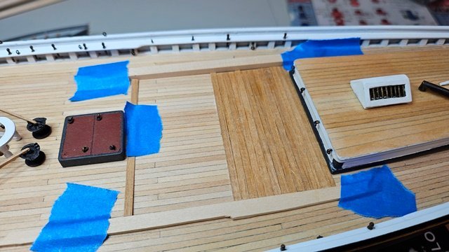
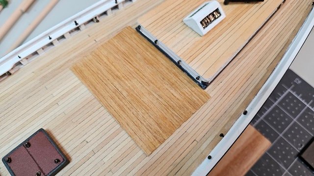
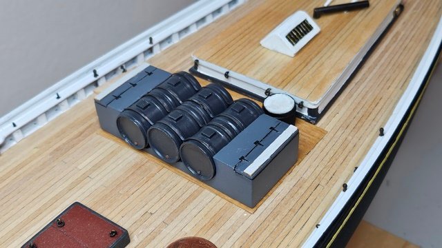
The plans call out a sheathing area on the deck just in front of the cabin. This is where the drums are located. In pictures the sheathing looks to be low quality boards and a bit beat up. I chose to use some thin walnut strips that were the approximate size to what is in the photos. Because this is an area that uses cheap lumber, I only lightly sanded the boards and left them natural color with a clear flat applied to seal the wood. The boards were cut with a cutoff saw to the same length. To ensure they were straight a couple scrap pieces were taped to the deck to keep them aligned during gluing.
-
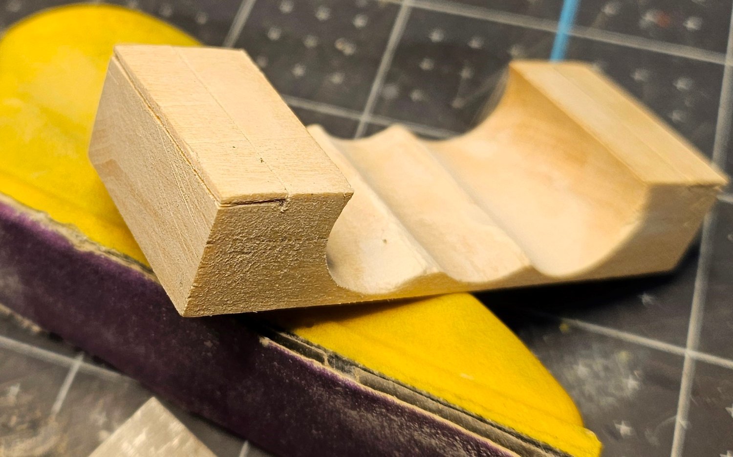
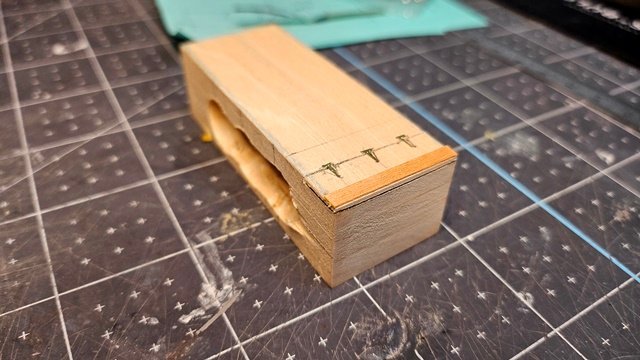
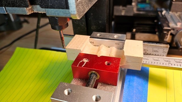
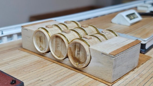
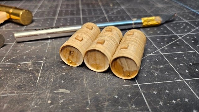
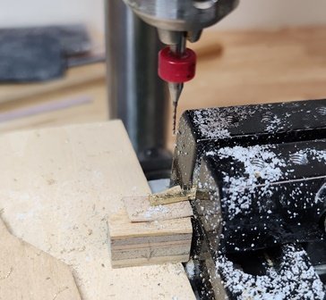
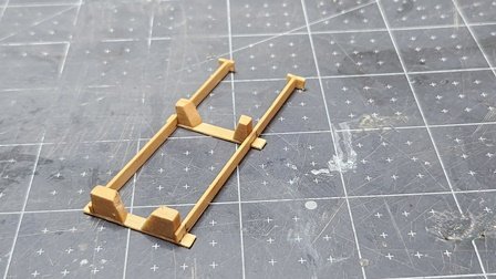
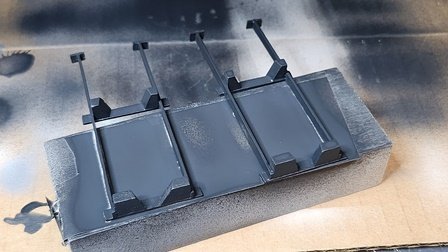
Next the cabinets with the integral skid. This started out as a solid block cut to the dimension of the part. The height was larger than the finished size to allow the three holes to be drilled in the block for the drums. This was done using successive sizes of end mills as twist drills were too aggressive in the soft wood and tended to tear it. The final size was done with an adjustable reamer to allow precise fit for the drums. The holes were just a but undersized at this point. That will be important later. I experimented with cutting grooves in the top of the block to find the best method of simulating the cabinet door. I attempted to make hinges from .001" brass foil. This did not work consistently. Bait cutting boards were made at this time. The mill was used to cut the block down to the cabinet size opening the top. The final grooves to simulate the door were made with a razor saw and Exato knife. This is where the undersizing of the holes comes into play. The drums snap into the cabinet block. Because the holes are slightly small a bend is produced in the bottom of the block. The adjustable reamer is used to widen the holes just enough that the bend conforms to the curve of the deck. This saves trying to sand the curve into the block. Flat brass wire was used to make the hold-down straps. Blackened with Casey's Brass Black. Hinges this small were difficult to make with the brass. Hinges were made from paper of the same thickness as the brass. An actual hing of 1/16 to 1/8 inch thickness would be ~.064". Which scales to .001". Paper is much easier to cut with an Exacto knife. After drawing the hinges to scale on the paper, the reverse side was painted flat black. The hinges were cut out with the paint already applied. The block and drums were shellacked, sanded, filled with wood putty, sanded and painted. The drums and hold-downs were fitted to the cabinet. The grooves for the doors were carefully cleaned and flat black applied inside the groove by putting paint on the Exacto knife and drawing it along the groove. The bait cutting boards were added and painted as well as the hinges glued on.

-
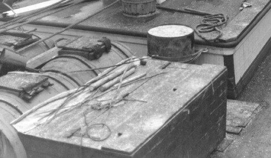
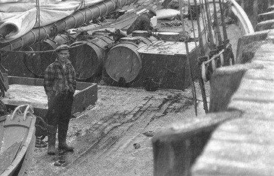
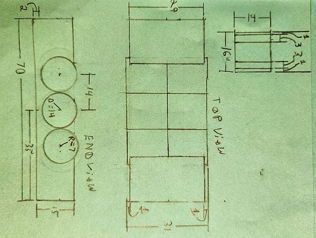
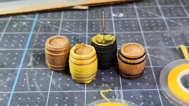
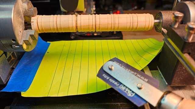
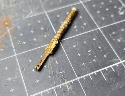
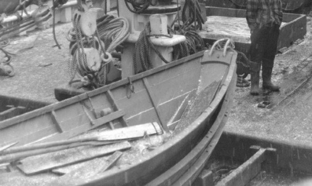
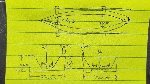
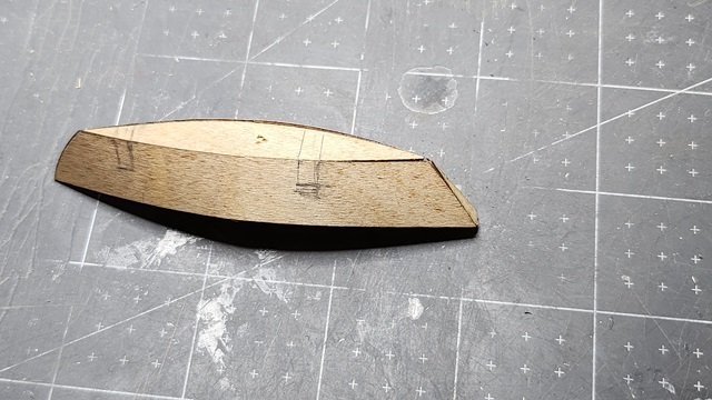
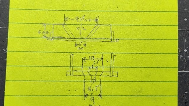
There is an interesting feature on the deck in original photos of Bluenose. There are six large drums in two rows of three sitting on sheathing with equipment storage cabinets. These are not shown on the Model Shipways plans. They add a lot of detail though. Presumably they are for salt or brine storage. Has anyone found these in other reference material? Fortunately, there is a figure standing nearby in one of the photos and the cabin is nearby. This allowed a guesstimate of their size. Some more details in another photo: These have hoops like barrels but appear more like drums in not having much taper. They are held in place by iron bands attached to skids that are integral with the cabinets. There are large hinged doors in the top of the cabinets. Each of the six drums has a small hatch on the top. One picture has what looks like a bung showing. The others are obscured by equipment. In the background is a steel drum tied to the cabin. After measurements of the model and plans and using the figure in the picture as a guide, I arrived at the following dimensions(in mm): I found some ready-made barrels that looked nice. I was able to mask them and get a nice wooden barrel look. However I was not satisfied. The barrels had much more taper than the drums and were too large to fit the scale reasonably. So I bit-the-bullet and started on the process of making my own. After experimenting I determined the best way to make the drums was to use my lathe and cut down a wooden rod. This also meant I could make all six drums in one pass. I turned the rod down to the drum hoop size and then cut a little deeper to get to the actual drum diameter. I used a razor saw to cut a thin groove between pairs to simulate two drums. Then cut a deeper-wider grove where the pairs separate. The drum pairs were then chucked in the lathe and the end lip cut. This was a bit of a problem as I had to hold the drum by one of the pair firmly enough to cut on the lathe. The chuck would mark the drum that was being held. My(imperfect) solution was to use padding and tape around the drum in the chuck. They turned out pretty nice though. The drums were shellacked and sanded smooth. A wood strip of suitable size was sanded to a curve on one side that matched the curve of the drum. This was cut into the hatches for the drums. After gluing the hatches, a small hole was drilled on the ends on the opposite side from the hatch and a small brad inserted to simulate a bung.

-
It's great to get back to Bluenose. I'm happy you were able to benefit. I've certainly borrowed from other modelers and like to pass it on.
-
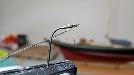
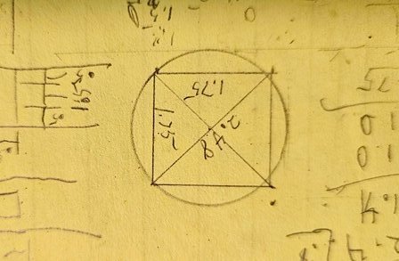
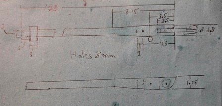
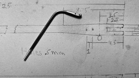
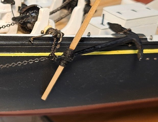
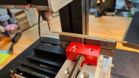
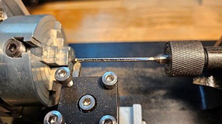
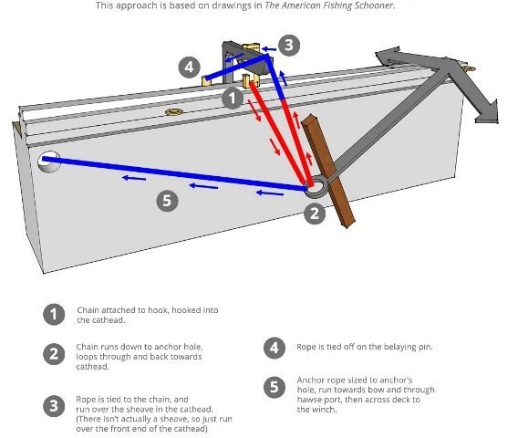
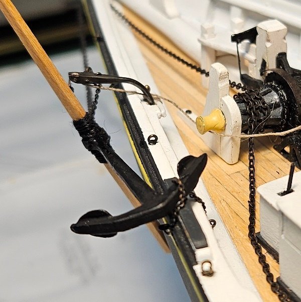
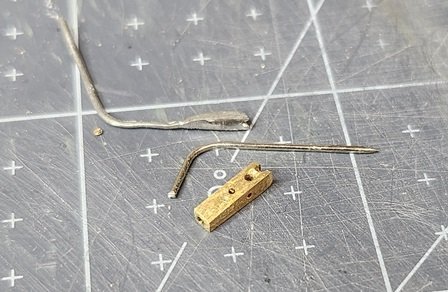
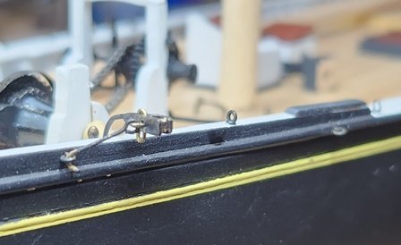
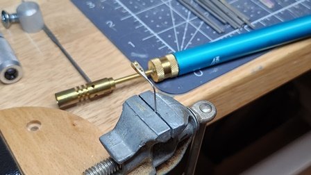
Interestingly, the increased precision machine tools provide requires more thought up front. The plan is to take a brass rod or rectangle(rectangles are hard to find in really small sizes) and cut it to the dimensions needed. Here are the dimensions scaled from the plans: The largest dimension is 1.75 mm. A little trigonometry gives us the smallest rod that 1.75 mm will fit inside as 2.48 mm(~3/32"): The first step is to cut the rod to a rectangle of the largest dimension: At this time the holes were drilled in the wide end. A partial slot was cut to simulate a sheave. The mill made this easy as incremental small steps can be accurately cut to approximate a round object in the slot. The piece was then centered in a 4-jaw chuck on the lathe and the round part of the shaft cut from the bar: After the final dimension was achieved the shaft was polished. It was then reversed and clamped in the 3 jaw chuck. The rough shape of the sheave end was cut and then finished with a file and sandpaper. The part was bent with wire bending pliers and blacked with Caseys: There was no information on the plans about rigging the anchor. The only information on the was the location of the rigging eyes and belay pin. In researching this I found the "Suburban Ship Modeler". This is a really nice blog with excellent photography. Here's his blog about Bluenose anchor rigging. Be sure to check it out; https://suburbanshipmodeler.com/2017/04/09/anchors/ This is a diagram from that blog: Adding the various attachments was next. The through link was made with .5 mm brass wire. Two of the brass eyebolts supplied with the kit made the eye and hook. The closest chain to scale I could find was 42 link/inch copper from Model Shipways. This presented a problem as the link inner diameter would not fit over the .5 mm brass wire. I used .3 mm wire to make a connecting link. Though difficult to form and thread through the link, it works. The sheave axle bolt was a short piece of .5 mm wire cut slightly long and crushed in place with flat jaw pliers: Some closeups of the installed cathead and anchor:
-
The cathead is an interesting piece. It also turned out to be difficult to construct. My initial approach was to use a brass screw and cut it down to size with a mill in the drill press. Then drill the holes. I simulated the sheave by drilling two holes and partially milling the slot. A straight pin sized hole was drilled in the end. This was then soldered to the pin with silver solder and shaped appropriately with files and sandpaper. The initial cathead turned out not to bad but was not accurately sized. Note the supplied part next to the pieces. I could not manage to repeat the process for the other cathead. I made several attempts but could not repeat the first attempt. The brass screws are made from quite hard material and are difficult to work. This frustration fed my resolve to find a real machine tool solution. I'll describe the machine tool process in the next post.
-
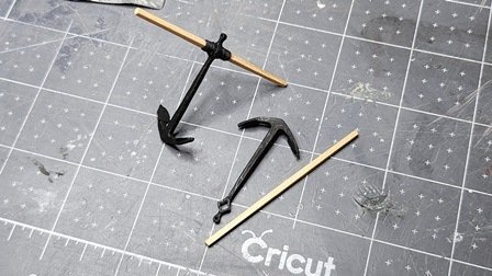
Next up; The anchor and ancillary equipment. The construction of the anchor itself is aided by the provision of a couple molded parts that only needed some cleanup. The drawing of the anchor in the plans is to scale. These are quite large anchors. I was surprised by the size of the cross piece. There's quite a lot of information on the anchor and it's utilization. However, there are no pictures of the original ship with the anchors secured on the ship or rigging diagrams for it. There is a nice drawing of the cathead, which is not the same scale as the rest of the drawing, but the scale is not noted. To finish the anchor I simply used a large toothpick shaped per the drawing and inserted into the anchor. This is held in place by seizing cord wrapped on either side of the anchor. The second anchor is not rigged but lays on the deck for display. Paint is simply flat black.
-
My last post was April 2023. It's been a long time. Last spring a series of unfortunate incidents started which has kept me from shipbuilding for some time. In the spring I discovered a upper story deck had been leaking under the siding of my house and caused rot which led to carpenter ants. There was basically a very tall toothpick holding up the corner of my kitchen. Anyway, that took me well into summer and I was playing catch-up until late fall. I'm now back to ship building!😃 For some time I've been growing more frustrated as I try to make accurate parts. Particularly metal ones. The old drill press isn't cutting (no pun intended) it anymore. I spent the first half of winter setting up and learning to use a "micro" lathe. That adventure is not directly part of Bluenose construction as it's the obtaining of a tool to work on Bluenose. I found a (relatively) inexpensive solution. For those who are interested you can find a post under the "Modeling Tools and Workshop Equipment" Blog: https://modelshipworld.com/topic/35937-inexpensive-mill-and-lathe/#comment-1026013 Onwards!
-
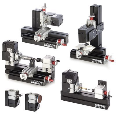
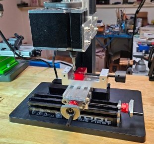
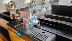
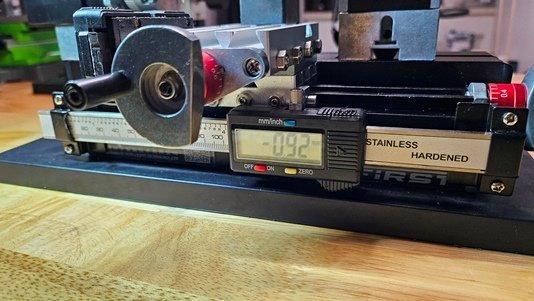
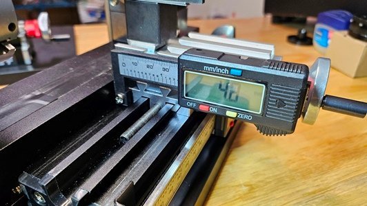
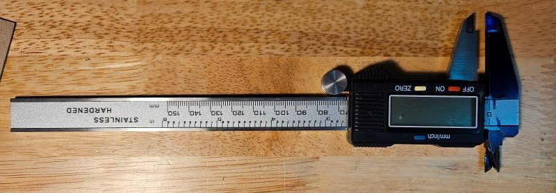
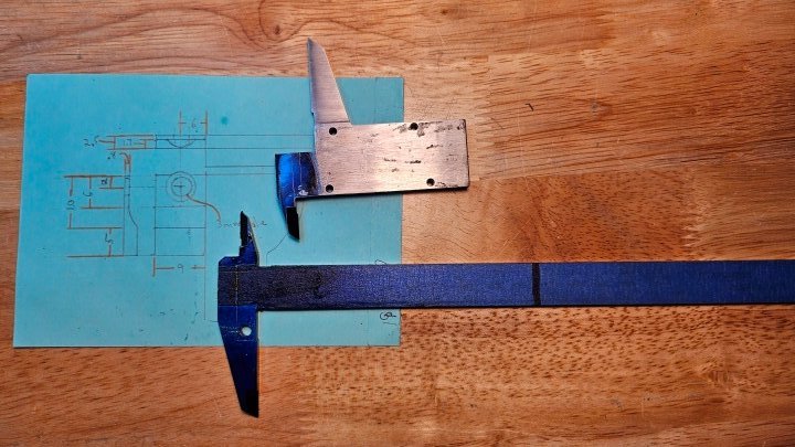
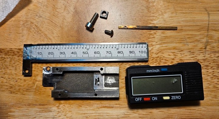
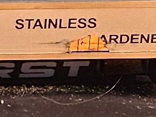
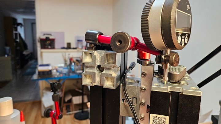
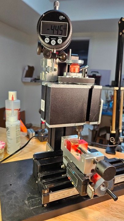
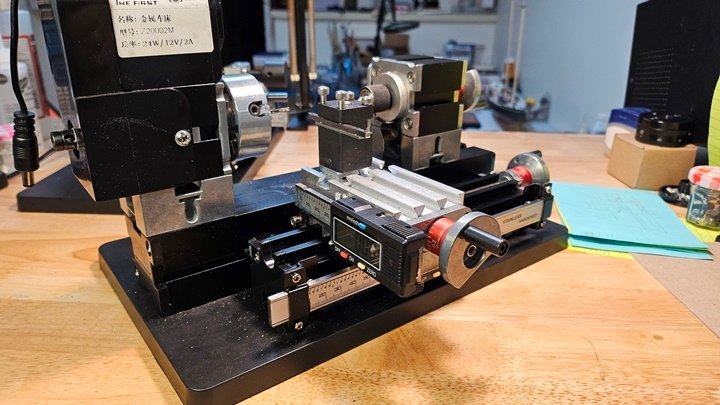
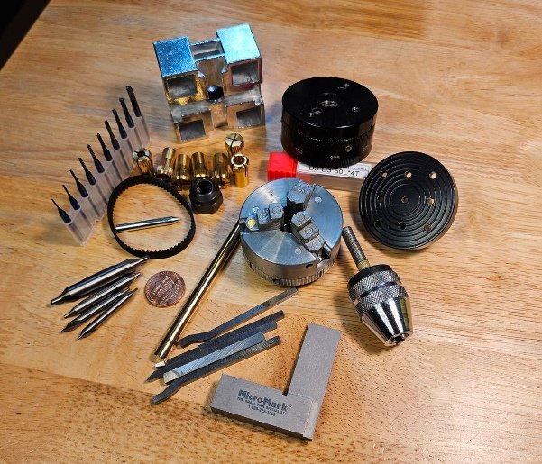
I occasionally need to be able to make a precision metal part for my modeling work. For very small parts it's hard to keep the precision needed by the scale when doing hand work. I looked at available lathe and mill and combination machines such as the popular Sherline. This is a fine and versatile tool but the $3000 price tag is high for occasional hobby work. A cheaper alternative is the Unimat system. That's still $800 with tax and shipping. Parts and accessories are also expensive from the vendor. I did find an unused one on Ebay for $400. It was open box and who knows what might be missing. Also, while the Unimat is capable of being configured as many machine tools, it's only one at a time and needs reconfiguration to go from a mill to a lathe. Another consideration is whether such a cheap tool is capable of the precision I would like to achieve. For my purposes a resolution of 0.1 mm(.004") is sufficient. This seems a lot to expect from a cheap machine tool. I did a lot of searching online. I kept hitting upon really cheap machines that looked almost identical to the Unimat. Some were in other colors but they were all the same construction and the actual parts were identical. I also found I could purchase parts and accessories very cheaply for these. I decided to purchase a micro mill and micro lathe of this type and see what could be done to improve them. I found a lathe and a mill for $200 each. Along with accessories, tax and shipping the cost of two machines came to ~$500. The machines as delivered were actually better than expected. They were surprisingly robust and ridged for their size and cost. The brand was "First Tool". A search for parts found most items available from GK Tool. Because these all use the same parts I was able to download manuals and parts lists from the Unimat site. Interestingly, these were labeled "Cool Tool" and said "Made in Austria". Perhaps "Assembled" in Austria is more accurate as the ones purchased are identical except for the labels and they were definitely made in China. I spent considerable time adjusting the machines. In the end I was able to align them to my needed specifications. The worst part is the cross slides which use a nylon gib shim and are very difficult to adjust. The X axis slide that's on the base is much better. The design of sub parts such as the tail stock and motor carrier use dovetail clamps that do a really good job of keeping everything in alignment and make configuration easy. There are flat plates that provide additional rigidity. You can see these features in the Unimat pictures. The motor on the lathe is a bit wimpy(looks just like the Unimat one) but the mill has a robust motor. The spindle speed is ~150 rpm. That's too low for some metals and too high for other jobs. There are no speed controls or gear adjustments. Here's a picture of the mill as delivered. The vise is a separate purchase. The supplied one was complete junk. There was a plastic base plate supplied. I recommend replacing that with metal or hardwood. The supplied tool rest was simply a dovetail clamp. I replaced that with the same tool rest shown on the Unimat. The throat height of the lathe was too small for a lot of work. I added centering blocks as shown in the Unimat lathe. I did find accessory gears and different size belts to accommodate them available. It takes a lot of searching though. These are DC motors so a variable DC supply should be able to control the speed. Remember though, these are cheap motors and they may not do well at higher voltages and currents needed to get higher speeds. It's probably better to figure out gear ratios and purchase them. The first thing I did after alignment was turn the mill motor 90 degrees. As configured it extends so far over the work area that you can't see the work. The cheap lead screws and indicator wheels were not consistent enough for my target resolution. The slides stayed aligned in their plane(as determined by a dial indicator) as long as too much force was not used. They will wiggle if much side pressure is applied. Probably the nylon gib shims. The backlash was pretty awful. Part of this was a size mismatch between the indicator wheels D shape and the lead screw's D shape. I applied a shim to the flat of the D which helped a great deal. The lead screw itself is slightly inconsistent. I was able to achieve good results by careful measurements while machining and sneaking up on the dimension needed. During this trial and error period I found and tightened parts to make things more ridged. The backlash could not be controlled consistently. I determined to add X-Y DRO(Digital Read Out) for the lathe and X-Y-Z DRO for the mill. While shopping for the machines I ran across very inexpensive digital calipers and dial Indicators. These all have zero setting capability and dual inch/metric readout. Some will even read out fractional inches. The fractional capability is impressive in such an inexpensive tool, but I'd be happy if I never see another fraction. I found a DRO specific indicator with mounts in stainless steel that was the right size for my machines. Amazingly, 0.01 mm resolution and +/- 0.02 mm accuracy for $15! Mounting was simply a matter of using the dovetail in the side of the X axis slide to mount the brackets. I then made a small block to connect the moving part to the X slide. My first precision part! It was necessary to drill and tap a hole in the slide to mount the connector. That worked for the X axis but the Y axis is much smaller with limited space for mounting. I bought a plastic digital caliper for $2 to cut down for the Y axis. The plastic was easy to machine but the accuracy was only 0.1 mm. This turned out to not work well. To get 0.1 mm on my work I really need to read 0.01. Otherwise the reading is +/- 0.09 and you don't know how close you are to 0.1 mm. I went back to shopping and found calipers with 0.01 mm resolution and 0.02 mm accuracy for $11 in stainless steel. Unfortunately there are none available in plastic with that resolution. That made for great difficulty in machining. Here's the plastic part mounted: Here's the stainless replacement I bought for $11 with the required accuracy: Here it's disassembled and marked for grinding. Grinding because it's hardened stainless and my little machine can't handle that. Note the hole. That's for the mounting. That hole was the most difficult part. I had to use a carbide PC board drill to start the hole and then use successive drills to ream it out in increments of a couple tenths of a mm. Ordinary drill bits just go dull on this stuff. Same with the 3mm hole in the other part. Matching holes were made and tapped into the slides. Here it is ready for installation: It discolored a bit on the scale due to the heat from grinding. That's not important though as the scale is not going to be used. The silver part is simply a tape that's applied over the etched pattern the readout unit uses. Here's a picture of what that looks like where I had a misalignment that scraped part of the silver tape off: The Z axis for the milling machine is simply mounting a dial indicator at the top: Future improvements might be upgrading the motor or changing gear ratios, sturdy base plate, change the existing gib shims to copper. Some useful accessories: Micro square, drill chuck for tail stock, 4 jaw chuck(Comes with auto centering 3 Jaw), rotation adapter, face plate, centering blocks, mills, tool bits, Collets in various sizes, brass or wood rod for taping out collets, center drills, etc. There are good machining tutorials on YouTube. I particularly like Blondihacks. You can find books on machining at your hobby store and the library. Here's some pictures of the finished product:
- 1 reply
-
- 5
-

-
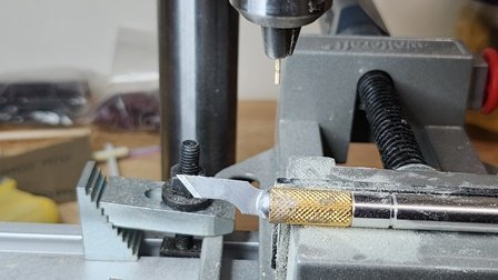
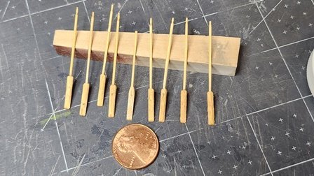
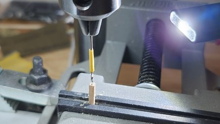
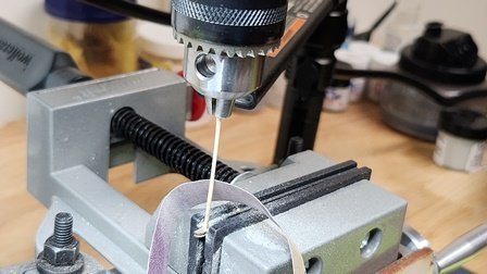
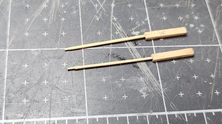
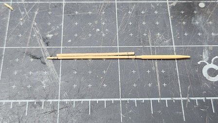
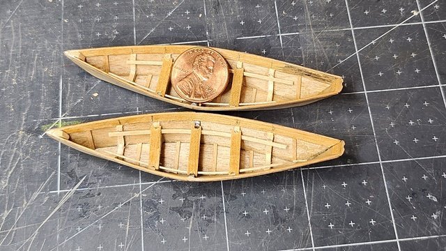
Oars. Who would think such a simple object would be so time consuming. The problem is they're so tiny. The shaft is 0.9 mm(scaled from the plan) and the handle on the end is only half to three-quarter of that. I looked around at hobby supplies online for oars. While there were plenty of options none were quite right for Bluenose dories. Had to make my own. My vision isn't what it used to be and I'm shakier now. I broke a few of these, especially the handles, during construction. I decided to make the oars as two pieces. The shaft and blade separately. First blanks for the blades were cut from 1.5 mm stock lumber. These were clamped in the drill press and a 5 mm deep x 1 mm hole drilled centered on the end. This is tricky because the hole must be centered and drilled perpendicular to both sides of the piece. If the hole is angled the oar shaft will be at an angle. I used the smallest toothpick I could find. This makes a sturdy shaft as toothpicks are hardwood. Because I don't have a horizontal lath I created a vertical one using a small piece of brass with a .75 mm hole clamped in the vise for a support. The hole was carefully centered under the spindle of the drill press. Using moderate speed and a strip of 220 grit sandpaper the toothpick was reduced to .9 mm diameter. Broke a couple before I got the pressure right. A gauge was used to mark the shaft for length and for the handle on the end. It looks like this when it comes out of the chuck. Note the gauge and marks for cutting. After cutting to length, the shaft was reinserted into the chuck upside down. An Exacto knife was used to carve the handle while it spun in the drill press. This was touchy work. The piece is now so thin that only extremely light pressure can be used. A firm hand is needed. Next the two pieces are mated using PVA. The bond is about as strong as the wood itself. Ready to sand the blade shape into the block. I used a small sanding block and lots of patience. Delicate work. Notice I broke one of the handles. Fortunately I had made a couple extra. After that, the oars were shellacked, given their final shape and sanded. Painting very light objects with an airbrush is tricky. The air stream simply blows small objects away at even very light air pressures. I opted to use a thin strip of double-sided tape to hold them down. This meant painting one side at a time and waiting for it to dry before painting the other side. Here's the final result. Not sure the handles were worth the trouble. You really don't see them at viewing distance after painting;
-
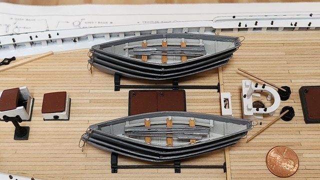
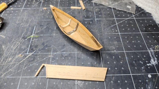
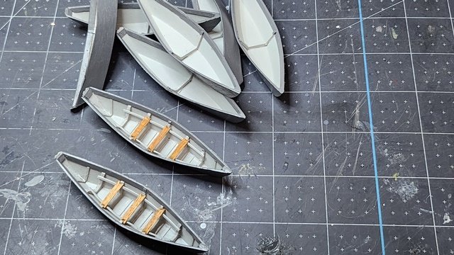
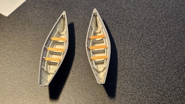
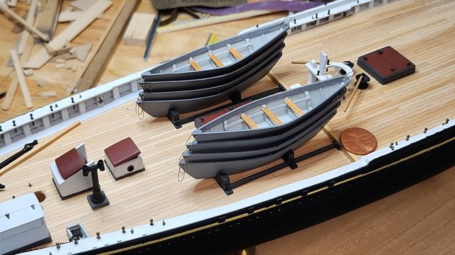
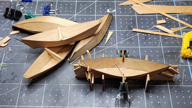
Time to put the frames into the rest of the dories! I chose to use .5 mm strip for the gunwales. This makes the total thickness 1 mm which is the thickness scaled from the plans. Looking at the photos of the original this seems correct. I did depart from the plan by making the height of the gunwale 3 mm as the scale size would have been .5 mm and very difficult to work. Actually looks pretty nice. Because the interior of the lower boats in the stack will not be visible, I'm only doing the center frame (for structural support) and the gunwales. Only the top two boats will be fully constructed. Making the frames was very difficult. Of the eight frames, there wasn't one that didn't break in some way. Trying to cut 1 mm basswood requires a delicate touch. The real scale frames would be .5 mm thick. TIP: use boxwood or some other sturdy material. Eventually all the frames were installed, trimmed and glued in place. Along with all the seats, cleats and braces. Again, for practicality, the frames are a bit larger than scale. Now the usual painting procedure. Sand, primer, fill, sand and top coat. I painted the exterior medium gray as that's what seems likely in the photos and the interior light grey for contrast and to bring out the detail. I drilled the holes for the lifting ropes and experimented with installing them. Due to the small scale the rope does not lay naturally. I'll have to do a little research on how to get a natural effect. Suggestions are very welcome. Finished top dories: After looking at the photos of prototype I noticed the ropes on the dories are quite stiff and stand up on their own. That means the ropes on my dories DO look accurate. I went ahead and added the lifting ropes to all the dories. Here they are in their cradles on the ship. I chose not to glue them down at this point as that would make rigging more difficult. I'll put them on permanently after rigging. I did drill the tie-down holes at this time. It felt good to complete some bit of the project.
-
Hi John Model Shipways also has a solid hull Bluenose model. Someone probably grabbed the wrong box lid when packing it. That's probably why the previous owner gave up the project. He thought he was getting a simpler kit. I really like the detail of your Charles Morgan. Nice work by-the-way. John U.
- 282 replies
-
- 1
-

-
- Bluenose
- Model Shipways
- (and 1 more)
-
I took a look at your Bluenose today. I really like the machine work and rigging. Looks sharp! John
-
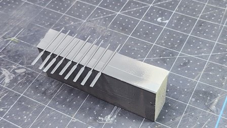
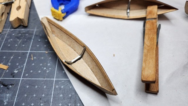
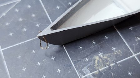
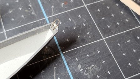
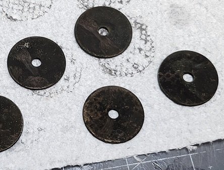
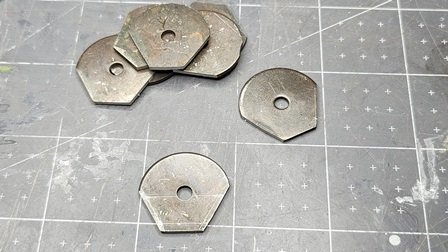
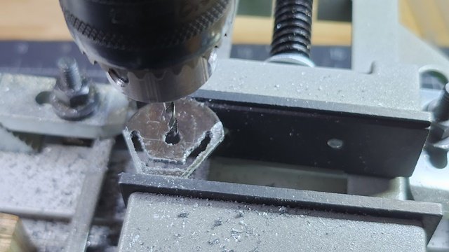
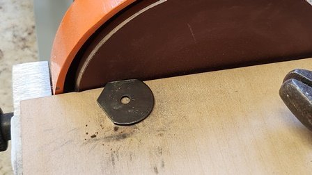
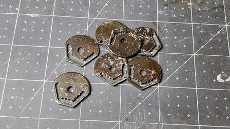
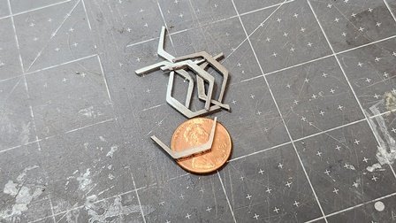
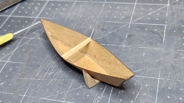
After looking into what other people have done for the dory frames, I didn't find anything satisfactory. I really only need one sturdy frame. The others can be made from basswod. Only the middle frame has any real force on it. I also took into consideration that only the top two dories need all the frames. They nest so tightly that no inside detail can be seen on the lower ones. After considering various materials I settled on steel. Hardwood will break along grain lines when made so thin. I didn't have any suitable thickness of brass bar in my shop. There will be a lot of waste in cutting these out and brass is expensive. Copper is too soft and would bend. Same for plastic. What I did have in my shop were some large steel washers. They were nickle plated and too shiny to mark with a pencil. I didn't have any machinists blueing around so I used Birchwood Casey Brass Black. That way I could scribe an accurate layout on them. After layout I used a bench disc sander to grind the sides to the layout lines. TIP: Use pliers or vise-grips. They get HOT! The sander was fast and did a great job of getting straight lines with a nice finish(240 Grit). Obviously this won't work for the inside cuts. The blanks were clamped in a machinists vise along each straight side in turn. The vise was aligned with the direction of travel of the X/Y table. This simplified cutting straight lines on the inside. First, a drill was used to remove bulk material. Then an end mill was used to create a nice finish for the inside edges. The ends were left attached during the drill/mill process to facilitate clamping while working the metal. A jewelers saw was used to cut the finished frame from the blank. Trial fit is good! A tick strip was used to transfer the frame location from the plan to the dory. Epoxy(for strength) was applied to the frame which was then clamped into the dory. The cross brace is removed at this point to allow the sides of the dory to conform to the frame. Much work but the results were excellent.
-
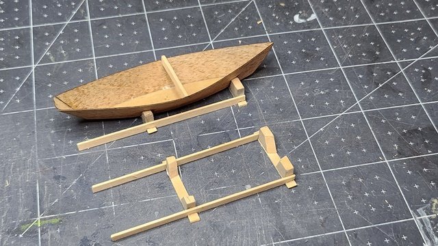
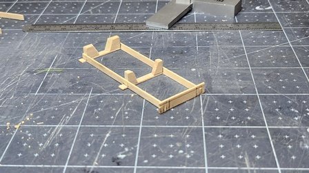
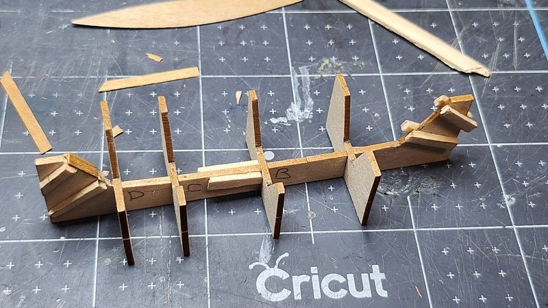
The deck cradles are simple but need carefully shaped chocks. My first idea was this: I laid it out on some scrap and cut out a sample piece. This didn't work out very well. I realized I needed a compound angle for the inside of the chock. To get better dimensions I drew outlines on one of the dories and took my measurements from that. This time the fit was very good. Only a little sanding and adjustment was needed. The end that attaches to the main beam has little blocks to locate it. These would be fussy to glue in place individually. Slots were cut in a piece of board which was marked with the correct dimensions. After the glue set I trimmed them to size. Then it was shellac, sand and paint. A dark grey was used(Model Expo Cannon Black). This was close to the appearance in photos of the prototype. Though it's hard to tell about color in B/W photos.
-
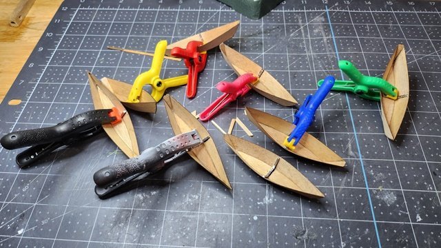
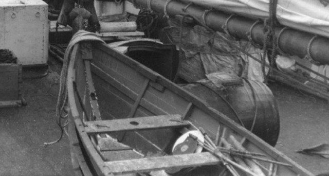
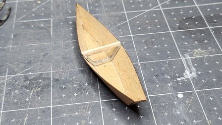
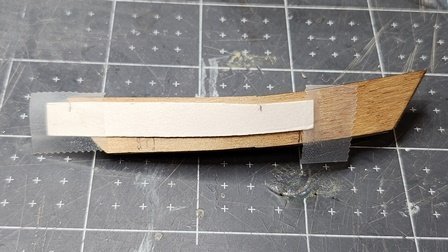
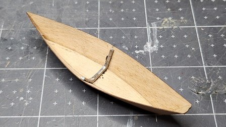
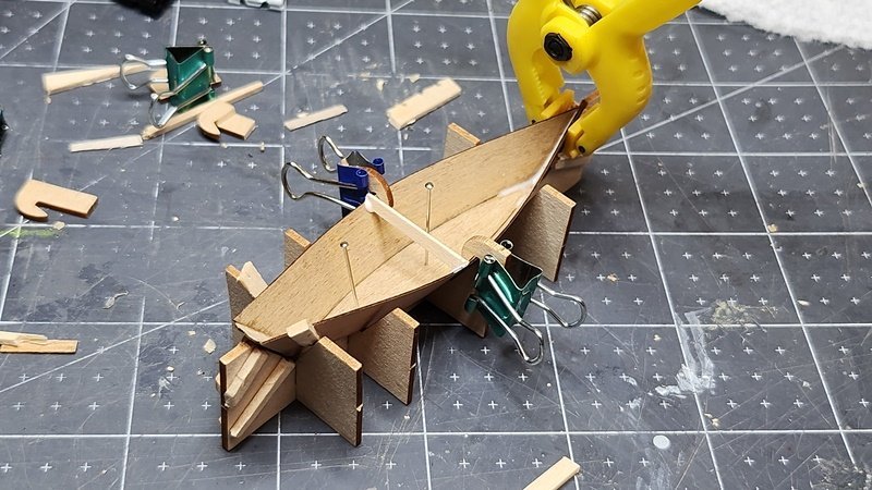
I've been busy for a couple weeks, Dr. appointments, volunteering with AARP taxaide, projects my wife wanted and some other R&R. Got back to the Bluenose this week. I decided to do something different for a while. I've been thinking about all those dories. They will add a lot to the model even though they'll be a pain. They're interesting historically as well. In the 20s, fishing schooners sailed to the Grand Banks and put out small boats(dories) with two or three man crews who fished from them, returning to the schooner with their catch. Thus the dories add a touch of realism as well as detail to Bluenose. Late Edit; This type of fishing is well described in a classic book "Captains Courageous". Check it out. I built the jig per the instructions. This is a Model Shipways specific item. I don't know how other kits do the dories. If you have another kit brand, I'd like to hear how your kit handles them. The assembly jig is included with the laser cut parts. The dory parts are also laser cut, but from much thinner and more flexible wood. It also appears to be a different type of wood. Somewhat harder and stronger than basswood. The instructions, as usual, are brief, consisting of one diagram and three paragraphs on page 24 of the manual. The details on Sheet 4 of the plans are more helpful. Be aware that the drawings of different parts are at different scales and not marked as to the scale. The layout of the jig is not obvious from looking at it. Pay particular attention to the drawing of the jig with a dory shown in the 3-D drawing on sheet 4. The bow of the dory is the curved end not the straight end. Here's what it should look like: I did add some spacers and reinforcements. Particularly in the middle where I used a pin to hold the dory bottom in place. This is made of thin basswod and repeated pinning will quickly destroy it. Also, while sufficiently strong for the job, the provided basswood hooks for clamping are easily broken. The wood used for the dories is very tough and springy. There's a lot of pressure required to hold the dory sides against the jig. I found through experimentation that only the two middle clamps were needed. In fact, if all the clamps were used the sides of the dory would not fit together properly. Because of the springy sides a temporary cross brace is need to hold the shape when the dory is removed from the jig. This springy action presents a serious problem. The thin material of the inner frames will collapse when the brace is removed - and it must be removed to stack the dories. I'd like to hear from anyone who has solved this problem and how they did it. TIP: if doing this again I would steam and pre-bend the sides like the hull planks of the ship. Getting the transom aligned is a bit fussy. I used a clamp at the bow to put enough pressure to close the top. PVA was used as the gluing medium. I spread a thin bead using a hypodermic filled with PVA and a medium needle(big enough to really hurt if stuck with). After the PVA set, I removed the dory and applied another bead to the outside for strength. The beads were thin enough they dried completely flat and are essentially invisible. Don't forget the brace! Technique established. Mass production! There's still quite a bit of work on these. The frames and transoms and rail caps. lifting ropes and their reinforcements. Accessories; oars, seats, etc. And, of course, paint.
-
Hi Gregg, When I was at this point I did the same as you. I looked at other builds and scratched my head about why the fit was so bad. Many others have had the same problem. I think it's due to not having enough detail in the instructions and people make the stern too wide. I only ran across one other blog that had the stern dimensions match the transom piece without modification. Keep up the good work! John
- 184 replies
-
- 1
-
-
- Bluenose
- Model Shipways
- (and 1 more)
-
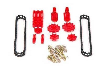
While looking for some tools I need, I saw this chain. It may be a better match for the original drive chain of the Bluenose. Mine is already fixed in place and I don't want to tear it up again. Anyway, for those of you who are looking here's the URL: https://www.micromark.com/Tamiya-Ladder-Chain-Sprocket-Set
-
Thanks for the nice comments. It's been a long time getting to this point. Almost done with the deck fittings!