HOLIDAY DONATION DRIVE - SUPPORT MSW - DO YOUR PART TO KEEP THIS GREAT FORUM GOING!
×


JohnU
-
Posts
170 -
Joined
-
Last visited
Content Type
Profiles
Forums
Gallery
Events
Everything posted by JohnU
-
I'm using Brass Black to blacken my brass parts. Works great! I have one problem with it. The blackening comes off easily. This is especially a problem for flat shim stock. The blackening comes of in flakes when rubbed. Is there some trick to making it bond to the metal? John
-
 Hi Per, I finally tracked down that build log with the glass recommendation. The guy who's a weathering guru. Here's a link to the page about glass. It's worth browsing the whole log. Lot's of tips and fantastic work. Be sure to check out the finished pictures. John
 -
Hi Bob, Thanks for your comment. I wish the nibbing had come out better. It adds an interesting detail to the model. Perhaps my skills will increase going forward and I'll have nibs worth showing. I figure bad nibbing is worse than no nibbing. On the other hand, if I don't practice I'll never be able to do nice nibbing. Modeling is a journey. The last nibs were better than the first nibs. It didn't turn out awful, but it was irregular enough to spoil the overall look of the model. By not penciling the nibs I ended up with the suggestion of nibbing which is a compromise. John
-
I'm looking for suggestions on deck finish. I've seen both pros and cons for using polyurethane. A number of people have used min-wax. I'd like to airbrush the finish as it is thin, uniform and leaves no out of scale brush marks. John
-
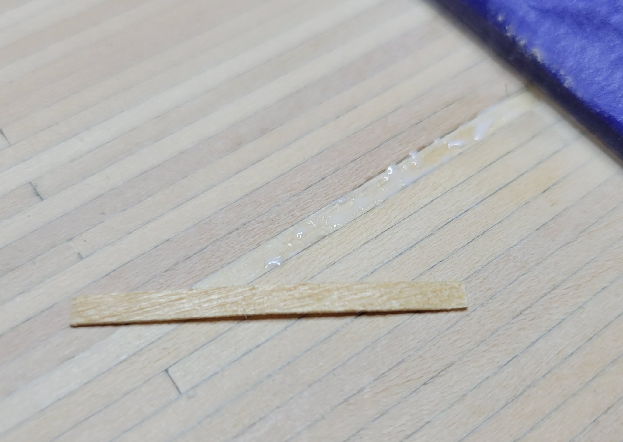
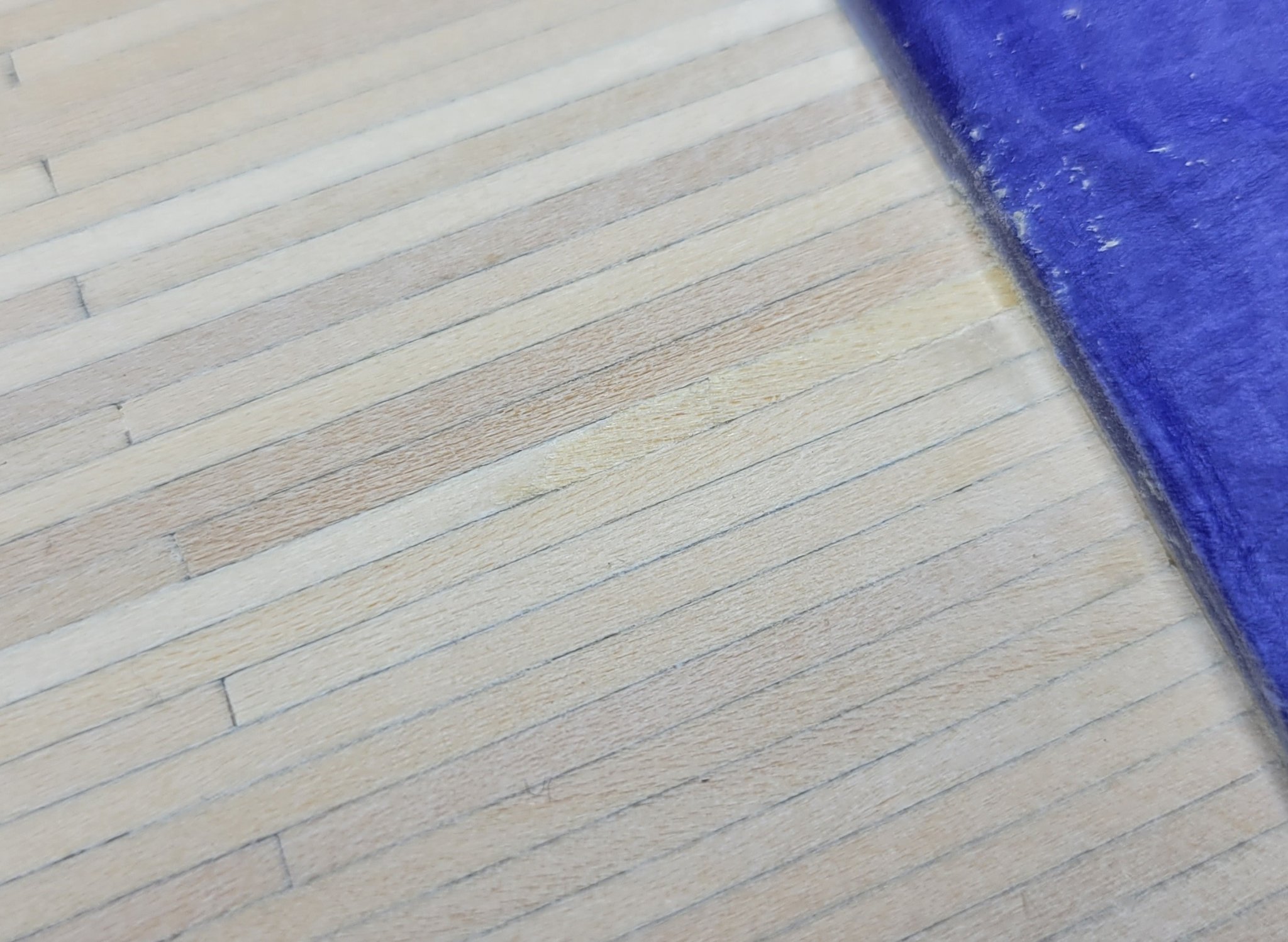
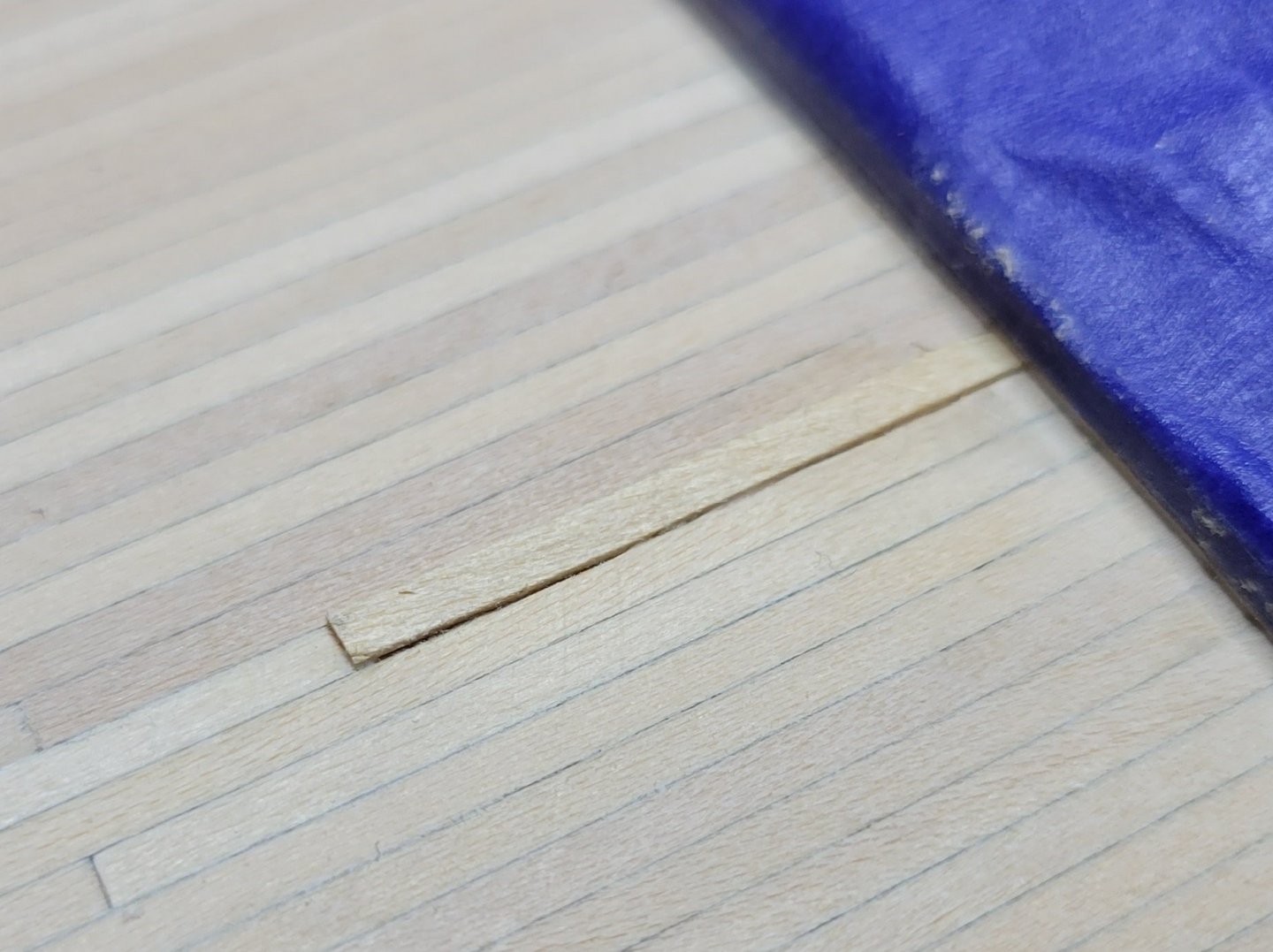
The deck is now sanded, minor repairs done and ready to apply a finish. The repairs were mostly cleaning and filling noticeable spaces between boards. There were only a few of those. There was one particularly damaged plank in a highly visible spot just in front of the great beam. The solution was to carefully gouge the plank to form a depression and glue a thick veneer onto it. Here's the repair: Used mini-plane to thin a plank to about 1/64" and gouged a grove to remove the bad spot. Forgot to take a picture before applying glue. Note the grove depth is tapered to the level of the deck. The plank is cut a little longer than the end of the taper and glued into grove. It's intentionally a little thicker than the grove depth: After the glue is thoroughly set, the plank is sanded flush with the rest of the deck. Here's the result. Except for a slight mismatch of the grain and color, the repair is invisible: This is my second planking experience. While it's not perfect, it's much improved over the hull planking. I'm getting better at it! Knowing my nibs were not going to be very good, I didn't pencil the nib part of the planks. Thy don't look too bad but I don't want attention drawn to them. Here's how it looks after sanding and before finish is applied: An overview:


-
Interesting. I bought some of that Scotch double sticky tape and it was about useless. Only good for holding paper. I try to stick something down and it just pops off. Maybe I got a bad or outdated roll. I eventually found some tape at a hardware store that worked well. It was sold for mounting things but was thin. I also bought some fabric tape to try. It says it's for "permanent" mounting and I worry about it being too strong. John
-
You could maybe resell to others in need of windows and recoup your cost. Set aside 10 or so for your own use and sell the rest for $1 each. John
-
Ahh, what price accuracy and detail!
-
Black is a more common color for steel. The black pins aren't true to the prototype but they definitely look nice. The brass looks good on a ship designed to look pretty. Especially with natural wood finishes. Not a true model though. Brass would require some sort of coating or it will tarnish over time. John
-
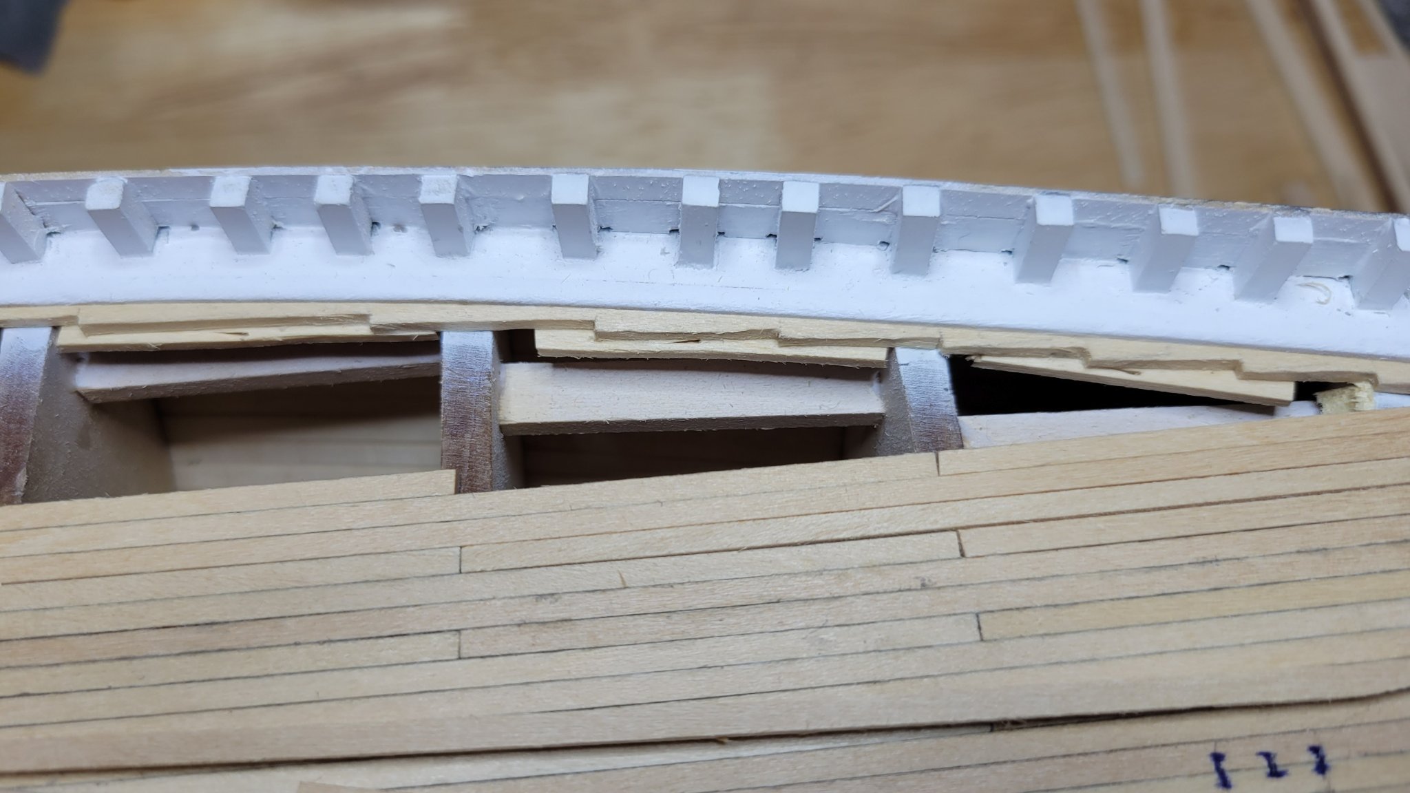
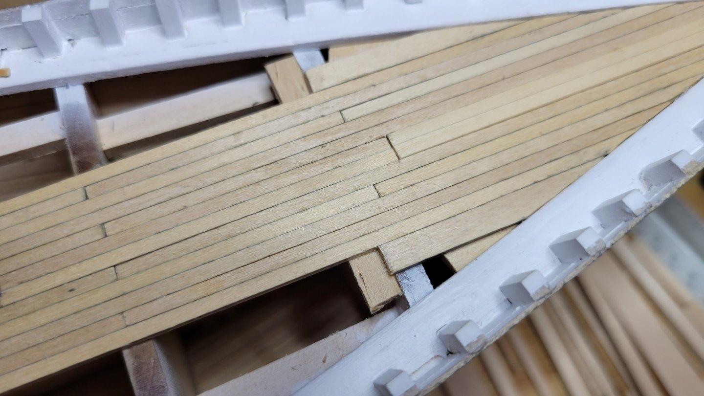
The fore deck is now installed. Because of the bulkhead problem the nibbing strakes could not be patterned from the plans. The difference in bulkhead width means the elimination of 1 1/2 planks. I achieved this by eliminating a plank on one side and using a hull plank on the other. The hull plank is the same thickness but slightly wider. I put this plank near the waterway so that it's not noticeable. Because I could not lift the nibbing from the plan, I had to do it plank-by-plank. The extra thick planks under the bowsprit were not a problem. Though they will be when I sand. At six planks from center I added the double wide planks for the windlass. The two planks that butt to the windlass planks don't fall on a bulkhead. To fix this problem I glued scrap wood under the decking to support the next plank ends. That takes me to 8 planks from centerline. Now the hand nibbing begins.🤕 As I've stated before, carving is not my strong suit. The nibbing strakes were cut to length and shaped using the same steam iron method used for the hull planks. This greatly eased the process. I tried two different procedures to see which works best. On the starboard side, I cut the nibbing strake and glued the nibbed plank in place As I went. I found it especially hard to control the shape of the nib and to make the orthogonal cut. All-in-all it was hard to get a consistent shape. For the port side I cut all the planks to approximate length and laid them in place; gluing only the pattern planks up to the nibbed end plank. With the planks laid in place, the nibbing strake was marked from the planks. The planks were set aside and the nibbing strake was carved and installed. The nibbed planks were then cut to fit the nibbing strake. This worked pretty well except my carving wasn't pretty. You can see the support boards for the unsupported ends. The waterway chamfer stands out when the nibbing strake is in place. Nice detail!

-
Hi Per, I dug into this a bit more. I found other logs where there was the same problem. Always Model Shipways kits. I also looked at your log and in the overview shots It appears to have the same slightly wider I & J bulkheads; though it's hard to tell from photos. I believe this is a mistake in the kit. They got the cutouts in the wrong order. If you simply swap the bulkheads the deck planking comes out exactly like the plans. John
-
Hi Per, While perusing you log I noticed you are using double-sided tape. I see that in other logs too. I've looked all over for a good double-sided tape but they are either too thin and designed for paper or too thick and designed for mounting parts permanently. What tape do you use? John
-
I was careful to mark them as I cut them out. I remeasured the cutouts and they still came out of order. I should not have taken the order from the position they were in before cutting them out. If I had actually measured them I would have been OK. It'll be fine in the end. The difference will not be noticeable in the finished model. Another lesson learned. John
-
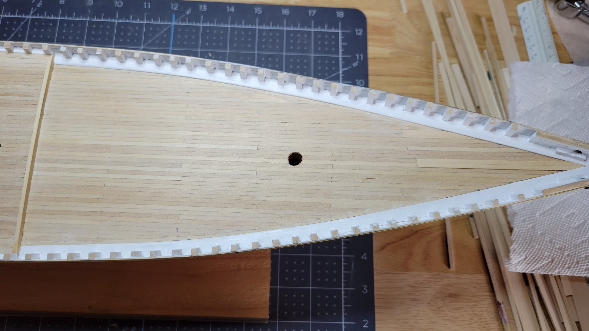
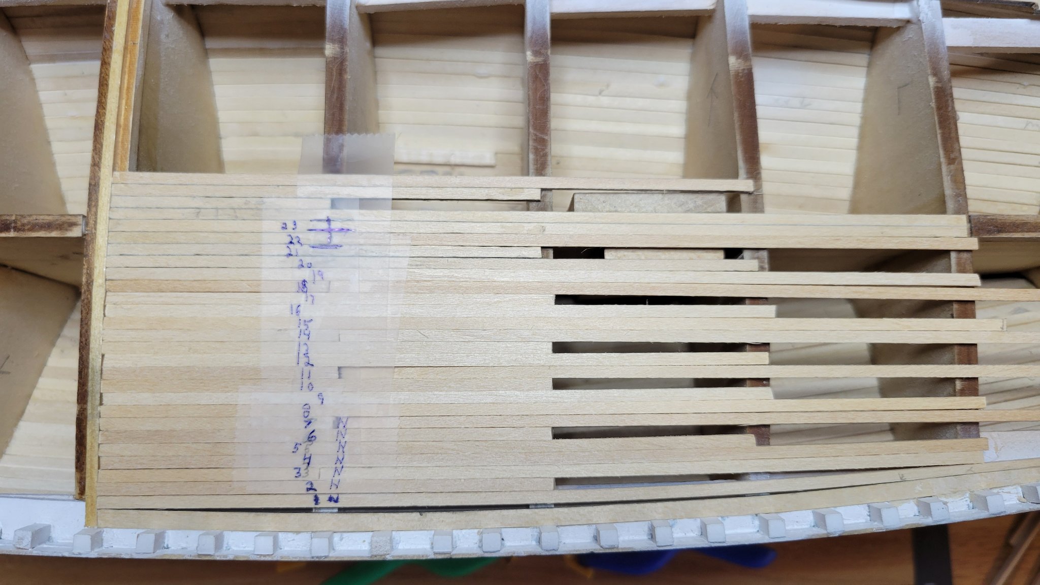
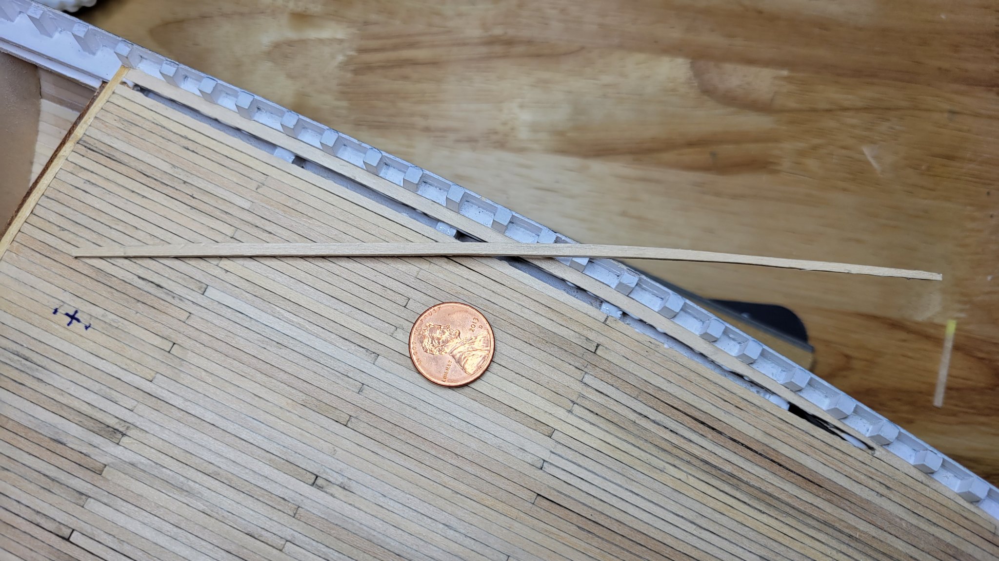
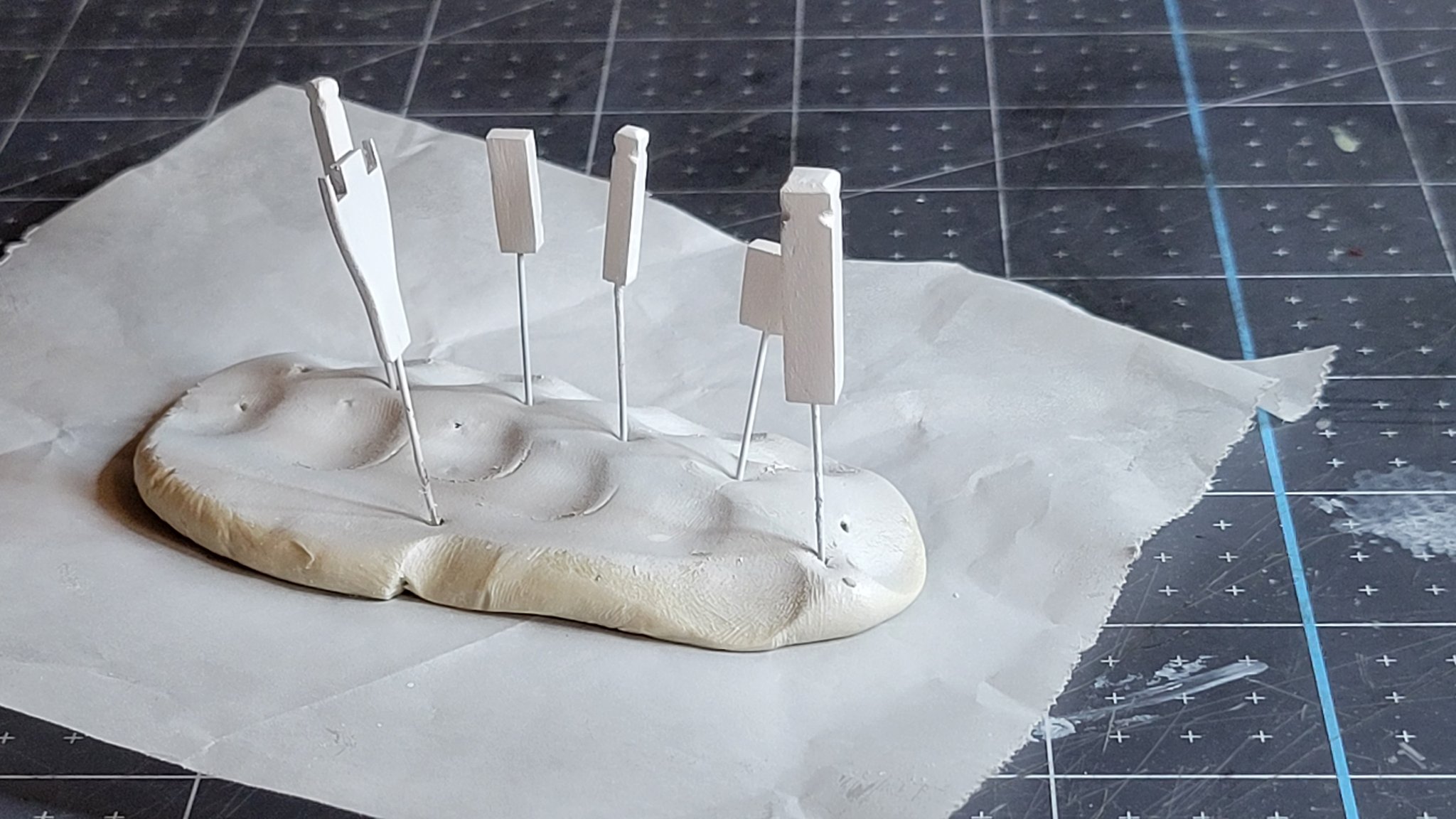
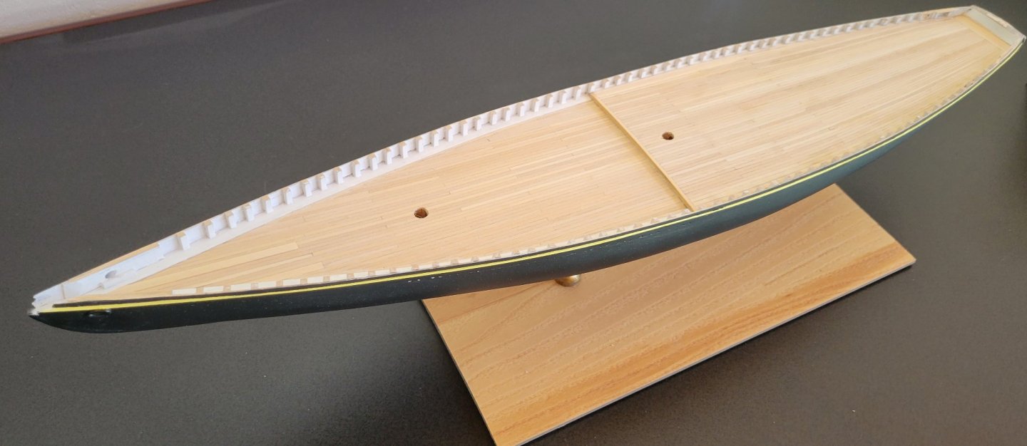
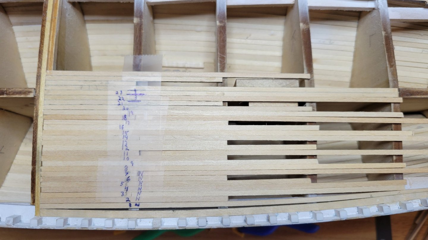
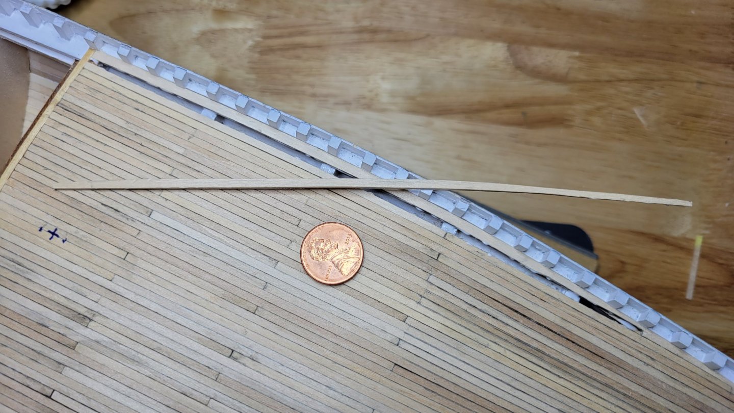
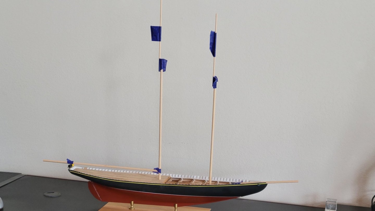
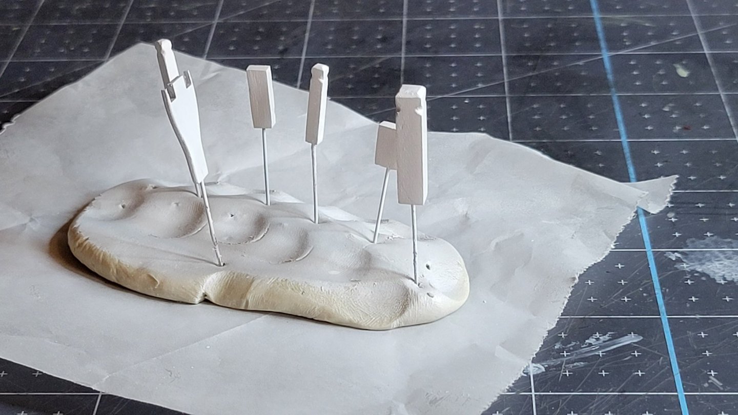
The quarterdeck is installed. On the Bluenose it's really more like a halfdeck, but I digress. This went pretty well using more or less standard technique. Much the same as the hull planks. There was a problem that I'm not sure what the source of is. The Model Shipways hull has come out with the widest bulkhead two positions aft of the great beam where the quarterdeck begins. This makes the deck planks come out differently than the plans which show the widest bulkhead to be at the bulkhead H (Great beam). Width H: 4.363" I: 4.424" J: 4.394" K: 4.272" As you can see I and J are both wider than H. I did not realize this until I started laying deck planks. The plans show the same width for H and I with J slightly smaller. This problem could have been avoided by swapping bulkheads to I-J-H order. Too late now. I had assumed the bulkheads were laid out in the correct order on the cutouts. Silly me. If you take I to be the correct bulkhead for the H position the decking planks are correct as shown on the plans. The plans show 24 planks from the center line at H along the great beam. 17 tapered planks and 7 nibbed planks(+ nibbing strake). That would exactly fit on bulkhead I. To fit them on H a plank must be dropped from the tapered group which would come out wrong for the aft end of the ship. Below is a trial fit that shows the problem: Given the actual discrepancy is less than a plank width, I decided on spiling for the last plank to compensate. Next some thought was given to plank size and pattern. A great discussion of buttshift patterns is found in the articles database on MSW. The most pleasing patterns use a five shift such as 13524. For a reasonable length plank such as scale 28', deck beams would need to be installed between the bulkheads at appropriate intervals. To use the existing bulkheads for the butts at 28' a 3 shift pattern is required. I decided to go with 132, but on reflection😄, that's the same as 123 but in the opposite direction. It doesn't look as good as 13524 but with the deck furniture It should be fine and it's a lot less work. I took the nibbing strakes directly from the plan. They were precut and sanded before installation. Planks were laid starting at the centerline and working outward. The taper was started at bulkhead K. The amount of taper was determined by measuring between the nibbing strakes at the stern and dividing by the number of tapered planks. This turned out accurate with little or no fudging. After the tapered planks were installed the nibbed planks were installed up to the last one. Which was spiled to fill the last gap. Here's the last plank going in! Don't forget to mark the mast hole!! I did this with the first two planks while I could still see the actual hole. At this point I could not resist putting in the masts to see how she looked! It's starting to look like a real ship.
-
Hi Ron, As the old saw goes: Necessity is the mother of invention. 😄 Part of the fun is working with ones hands. I could make lots of parts more easily with a 3-D printer and it would look really good. Not as challenging though. John
-
Thanks! I was getting bummed while I tried to sort out the airbrush. The key was not tightening the hose adapter all the way. After that things went my way again😄. Learning to use the airbrush was definitely worth while. The results speak for themselves. John
-
Hi Per, No, he just said medical supply companies. Anywhere they sell stuff for microscopes I expect. I wish I could remember the blog name. I was browsing in the tips and techniques forum under painting and ran across a question about weathering. A responder to the thread said to check out "...., he's the king of weathering" or some such. I'll try searching for it again. He WAS INDEED the weathering guru. He even went into detail about how to do a realistic broken window. John
-
Hi Per, Reading through your log tonight. Say this question about glass. There was a guy building a fishing trawler who used real glass slide cover for his windows. It's thin enough to be in scale and can be cut like any glass. He specialized in weathering and even made broken windows from this glass. John
-
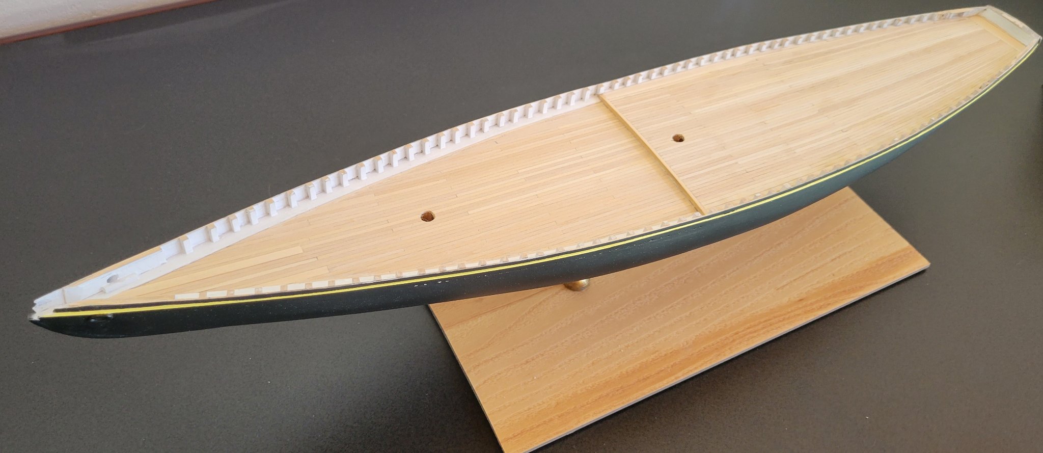
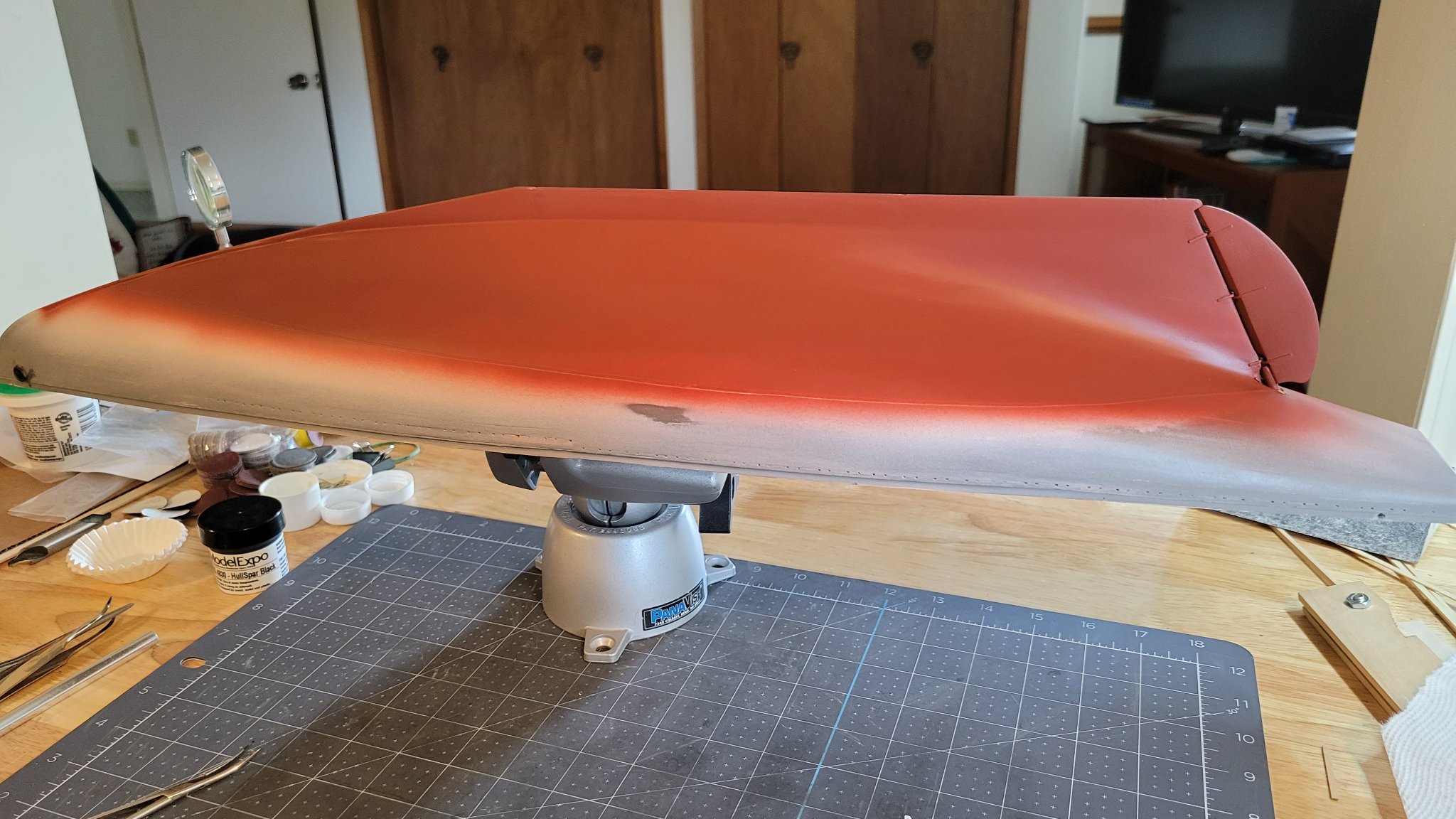
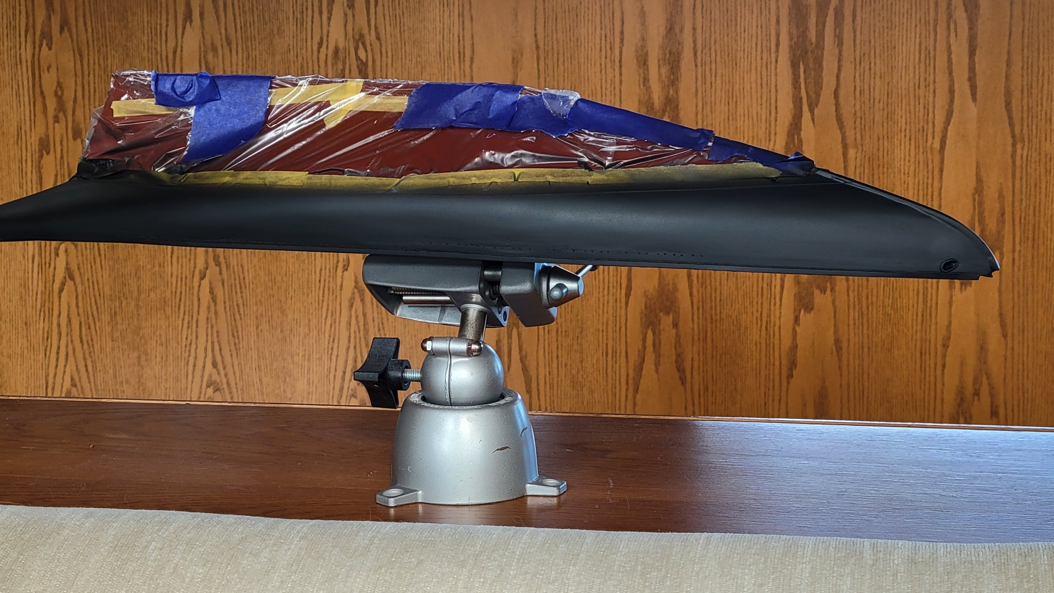
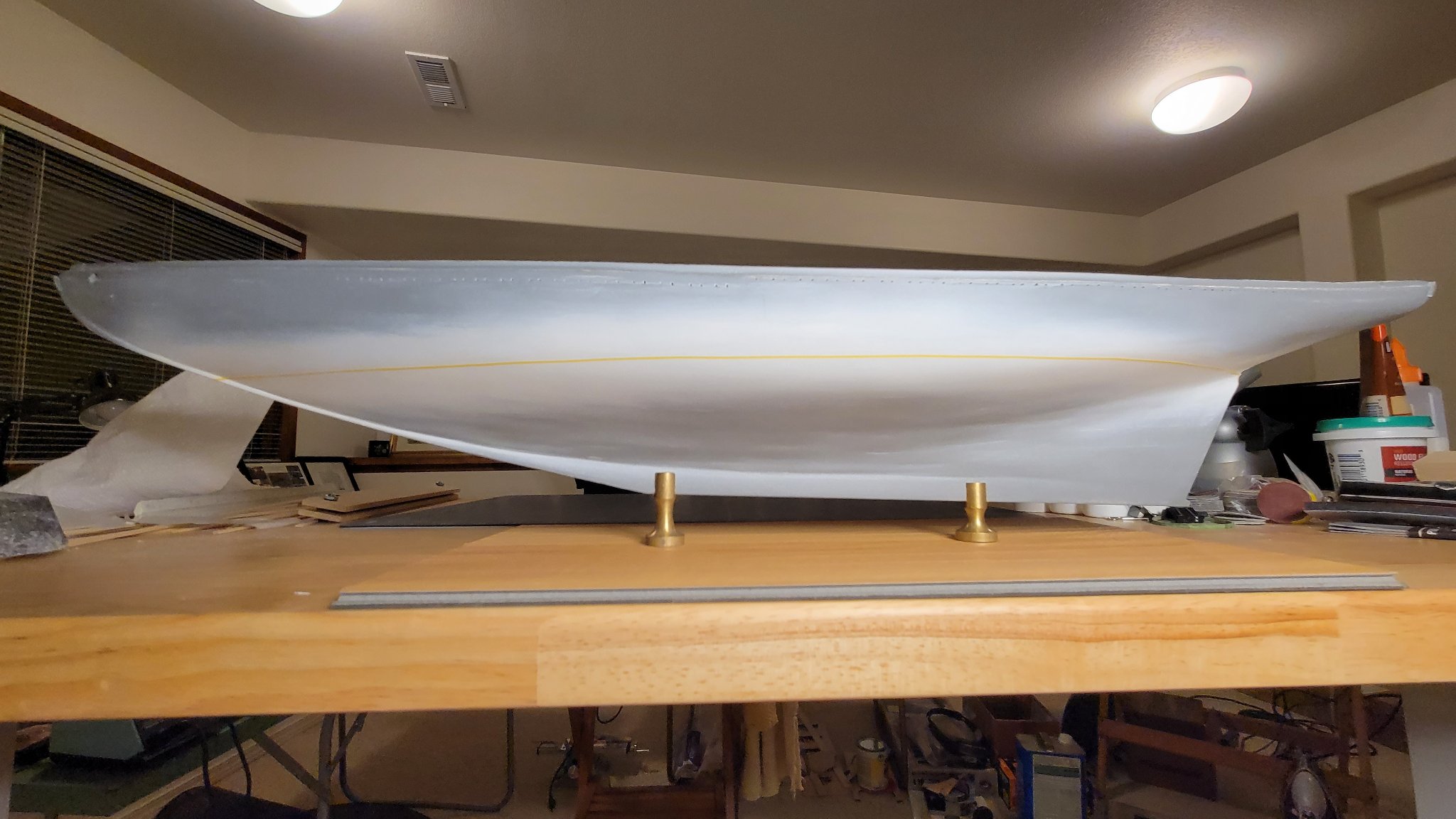
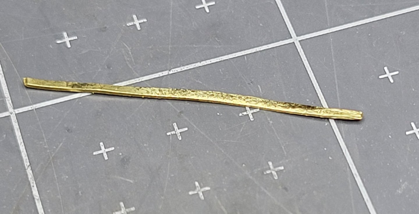
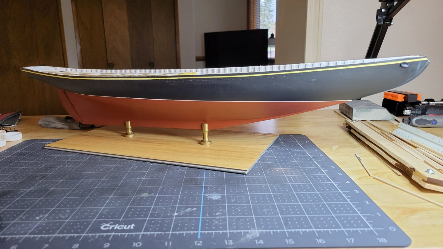
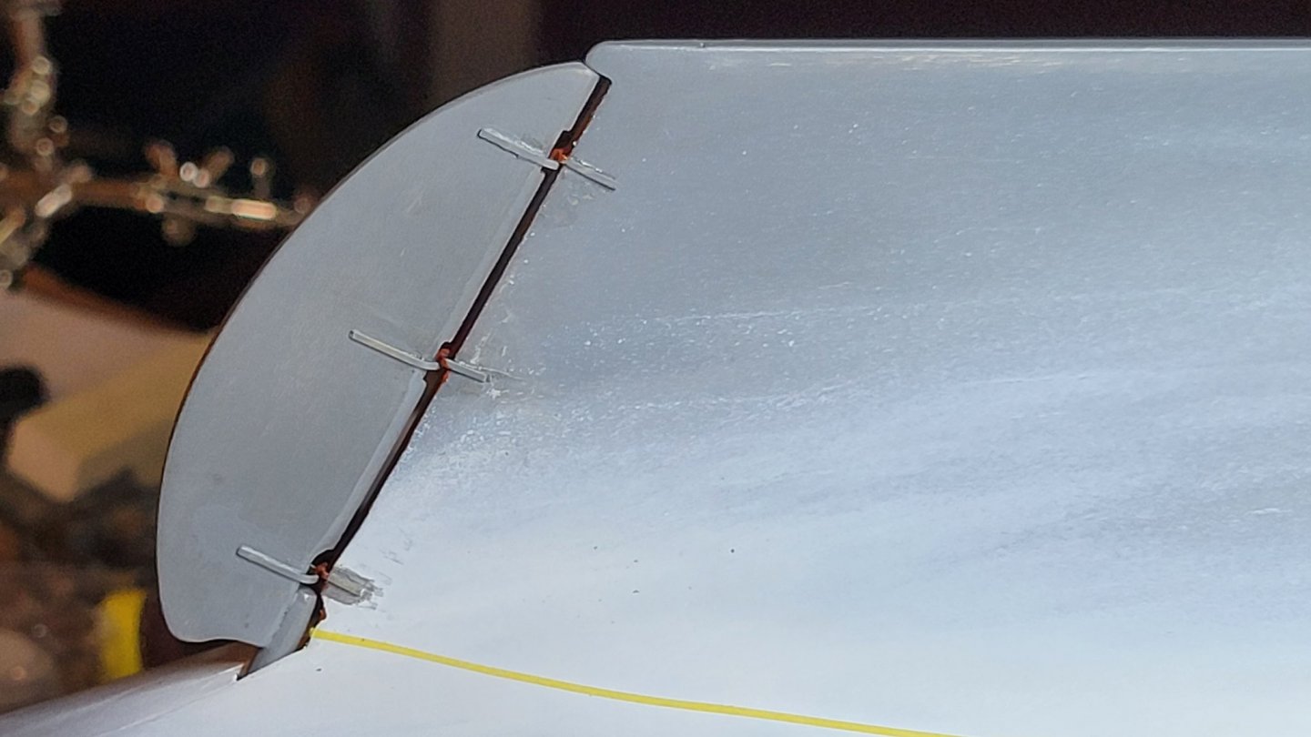
Once the airbrush and paint were dialed in the hull painting has been proceeding smoothly. So far, despite initial fiddling needed, the Model Expo colors have been spot on. After the white paint layer I had lots of runs. Paint was thinned too much. The mix was adjusted and the copper red bottom paint went on nicely with only a couple runs and one too thin area. This was due to my beginner skills which improve with each application. The second coat of bottom paint looks good. Time to move on to the top paint. While you don't see it in this picture the masking tape for the level water line white is there. Next was to mask off the bottom and apply the top paint. This looked grayish blue in the bottle but dries a nice satin black with just a hint of blue. This coat went on with no runs! No misses!. I'm getting the hang of the airbrush. Does a great job. Next I masked the yellow trim line just below the waist and above the scuppers. I followed the line scored into the hull earlier. This line was now very faint from the paint fill-in. There was just enough left to act as a guide. My masking skills now need to catch up with my newly acquired airbrush skills. When I removed the masking there were several leaks to patch up. The masking for the yellow line was not sealed well and I had quite a bit to touch up for that too. The white line came out very well. There were only a couple tiny touch ups near the stem. All the painting had partially filled the scuppers. I made a handy-dandy rectangular scupper clean-out tool from a piece of flat brass stock in the right size. Just sharpened one end slightly. Then it was time to mask the hull and paint the stanchions and water-ways. Here's the finished result. I'm pleased with the colors but still need to do a little touchup. I also added the rudder and set it on the temporary mounting board. It's time to do topside work! While I had the airbrush out and white paint ready, The pieces for the bowsprit mounting assembly were painted. The technique from the jumbo jib boom was used. Sand-seal with shellac-sand again and finish paint. Much better results than my first attempt. No Fuzzies!

-
Hi Per, I see lots of good recommendations for Vallejo. For the next project I'll try the pre-mix paints. For now, since I have the Model Expo paints in the right colors, I'll finish this model with them. After some experimentation I have found the right formula. It seems consistent from color to color. Since I solved the main problem with airbrush adapter I've been spraying away. I'm going to update the log tonight. I'm a happy airbrusher now. John
-
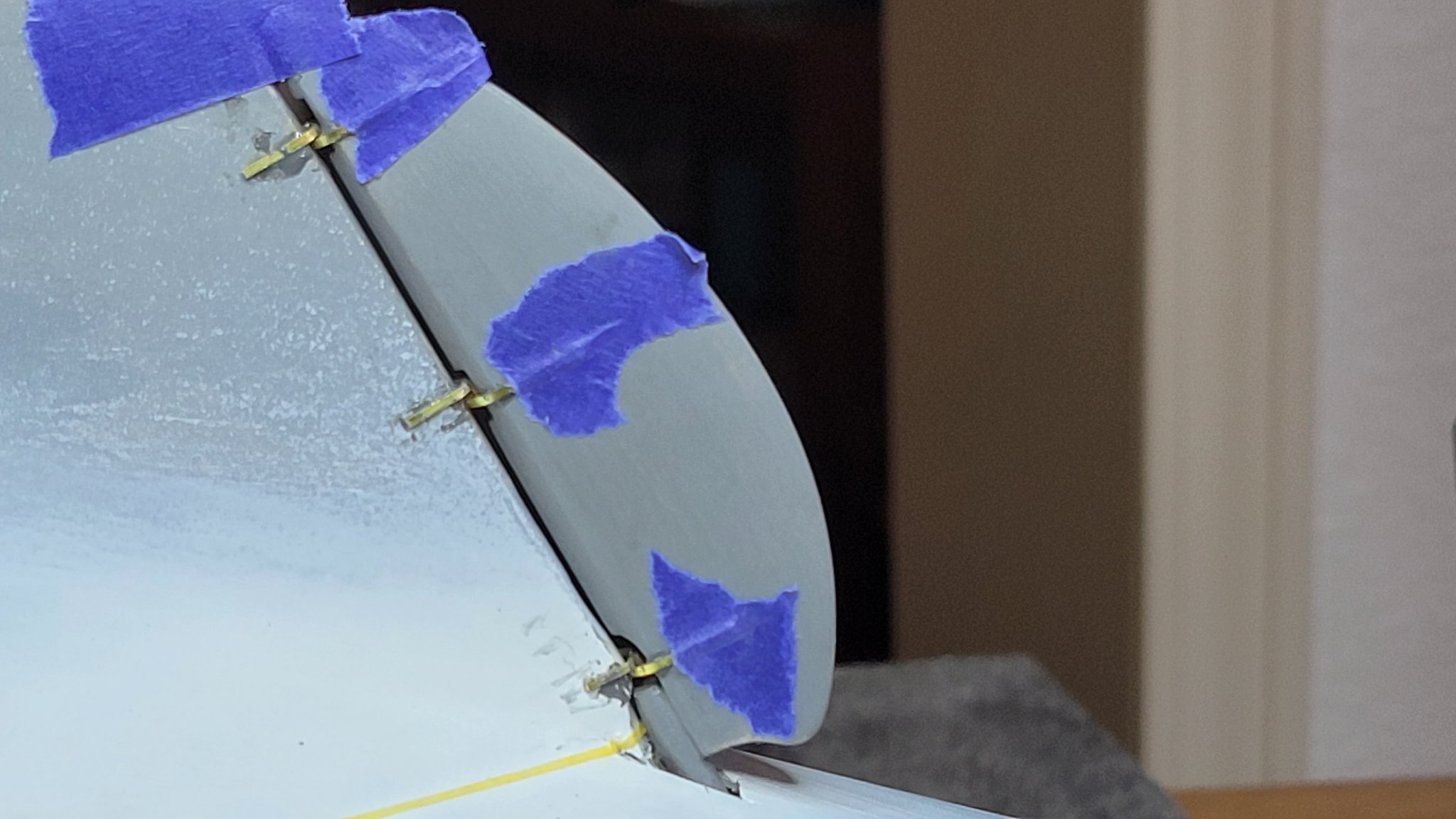
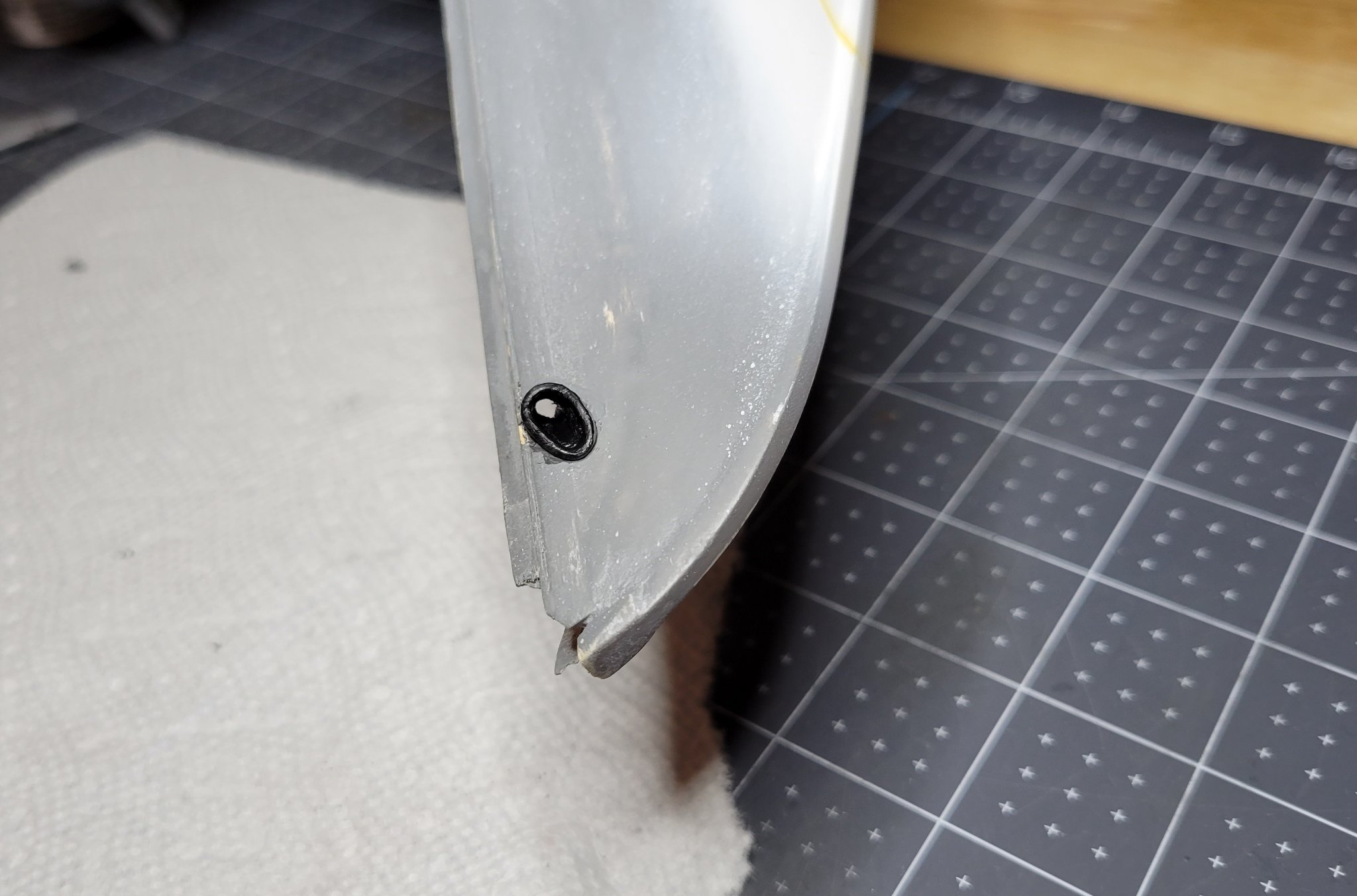
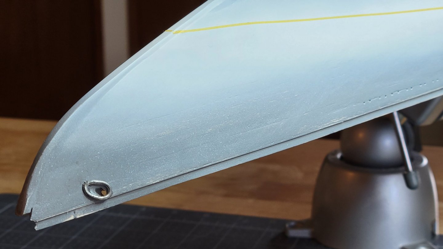
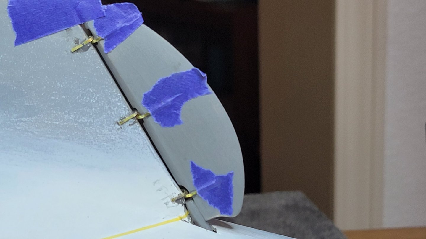
Almost ready to paint hull. The hawse pipes and rudder were installed today. I had pre-drilled the hawse holes and partly shaped them when the knightheads and hawse timbers were installed. Epoxy was used to ensure a good metal to wood bond for the hawse pipe rings. After the epoxy had set enough to hold firmly the excess epoxy was removed. Finished shaping and blending the holes to the ring was done with needle files. The black hull paint was used for the interior of the holes as the prototype appears to have the hawse pipes painted the same as the hull. I had shaped and primed the rudder while waiting for paint to dry on the hull. The pintles and gudgeons were also made earlier. The brass strap that came with the kit was the correct size and was cut and shaped appropriately. Rather than try to make an actual gudgeon and pintle at that small size. I simply soldered a tiny piece of the strap to the pintle strap. This worked out nicely and cannot be seen when assembled. Getting the straps mounted and aligned properly was the tricky part. This was solved by taping the rubber part to the rudder with masking tape then adjusting the hull part. Once a satisfactory alignment was achieved the rudder was removed and the position of the straps was marked with a pencil. These were then epoxied in place. The same was done for the rudder straps. After the epoxy had partly set I installed the rudder and made final tweaks to the position. The excess epoxy was the carefully scraped away. The brass was lightly sanded and primed.

-
Hi Per, Looked up your build again with specific reading of the painting. I see you had problems getting up to speed with the airbrush too. It's the only way to go for a really nice finish. Once I got the hang of it and sorted out my problems it went nicely. Still a little tricky with the thinning. All the articles just say "start with 50:50" and "consistency of milk"; whatever that is. I see you opted to paint white then mask water line and paint the upper and lower hull after. After seeing how yours turned out, I have high hopes for a nice water line. John
-
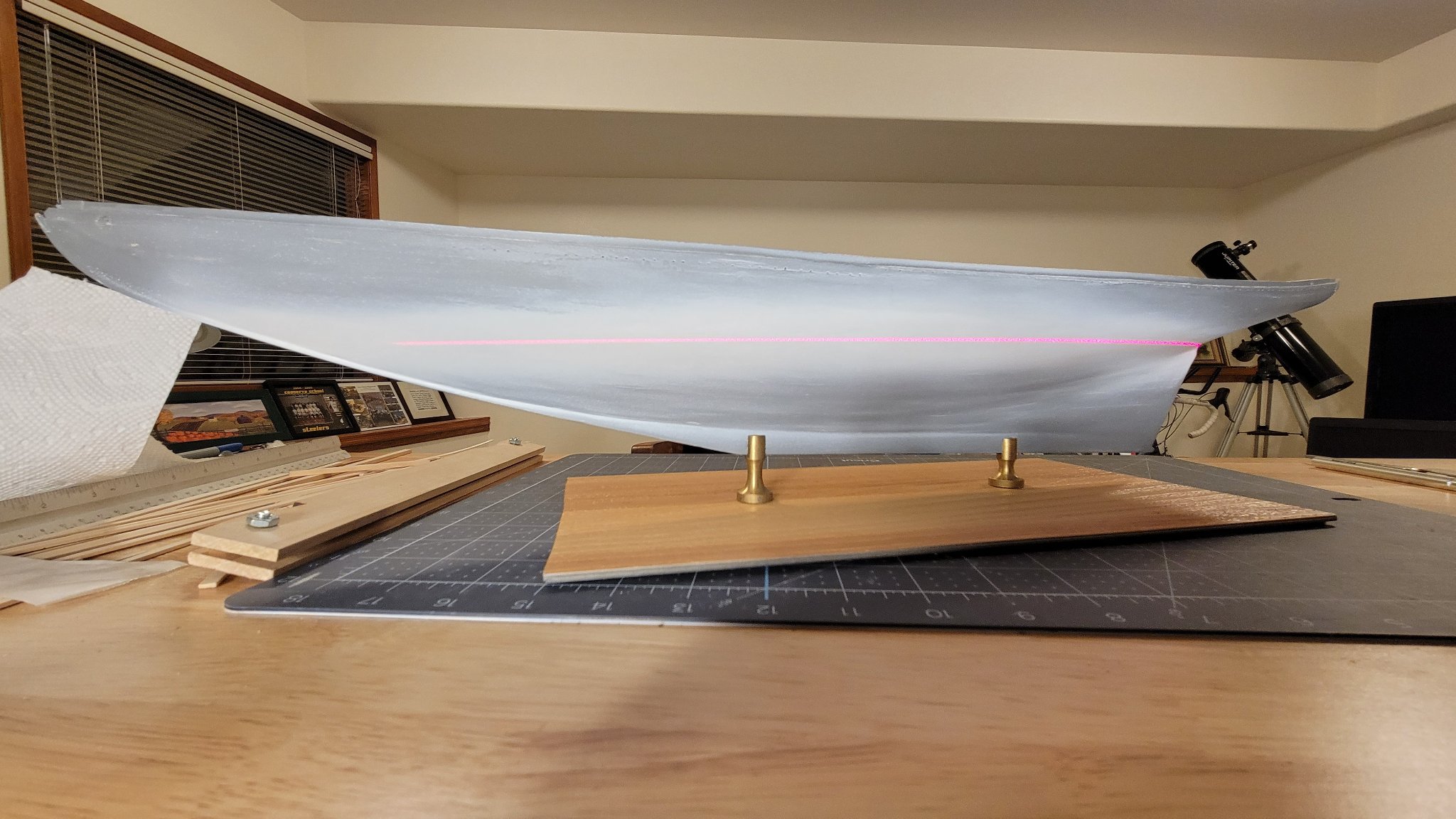
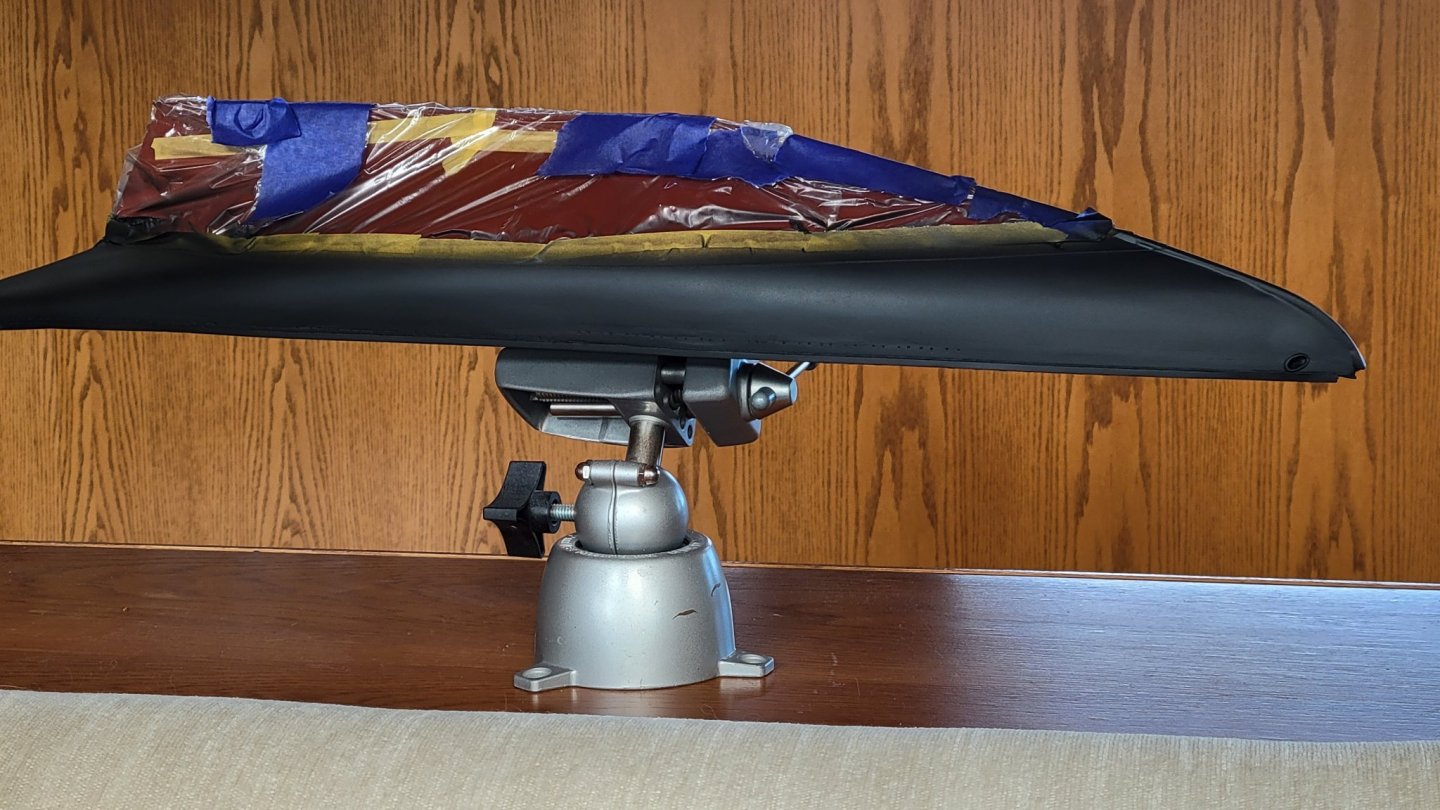
The hull was painted with a grey primer in the usual primer-sand-fill-primer iteration until the hull was uniformly coated and smooth as a baby's skin. I kept the paint thin enough the planks show very slightly. By the time the finish coat is applied there will be only a suggestion of planks. A wide white band was painted around the hull at the level water line. I used the laser level that worked for the windlass but in horizontal mode. This required the hull to be mounted on it's stands. This is an appropriate time to do the mounts anyway. A temporary mounting board was used for holding the model. The trick was to get the correct height as the keel on Bluenose has a slant to it. Fortunately, Model Shipways supplies mounts that are appropriate heights and pictures of the mounted model. It was fairly easy to determine the correct positioning. After the paint was dry and sanded, Tamiya 1mm tape was applied under the laser line. This was a little tricky as the tape is so small and I'm working under the hull. Came out pretty good. I burnished the tape. Hopefully there won't be seepage under it. The idea is that it's easier to mask a small area and paint over it than to create parallel lines of masking over the larger area to paint a thin line. Of course it's harder to paint dark over light. I may hit it with a light coat of primer to cover the white. We'll see how it goes. In any case it's fun again now that I'm not being frustrated with airbrush problems.


-
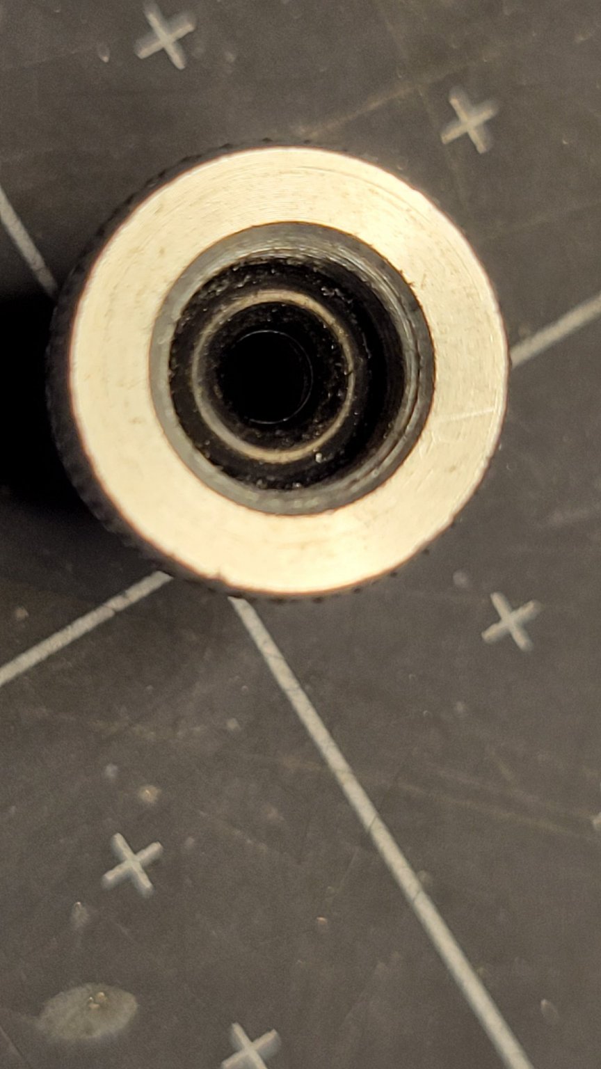
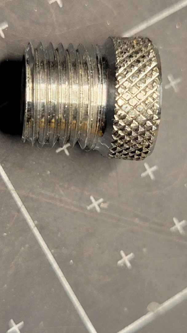
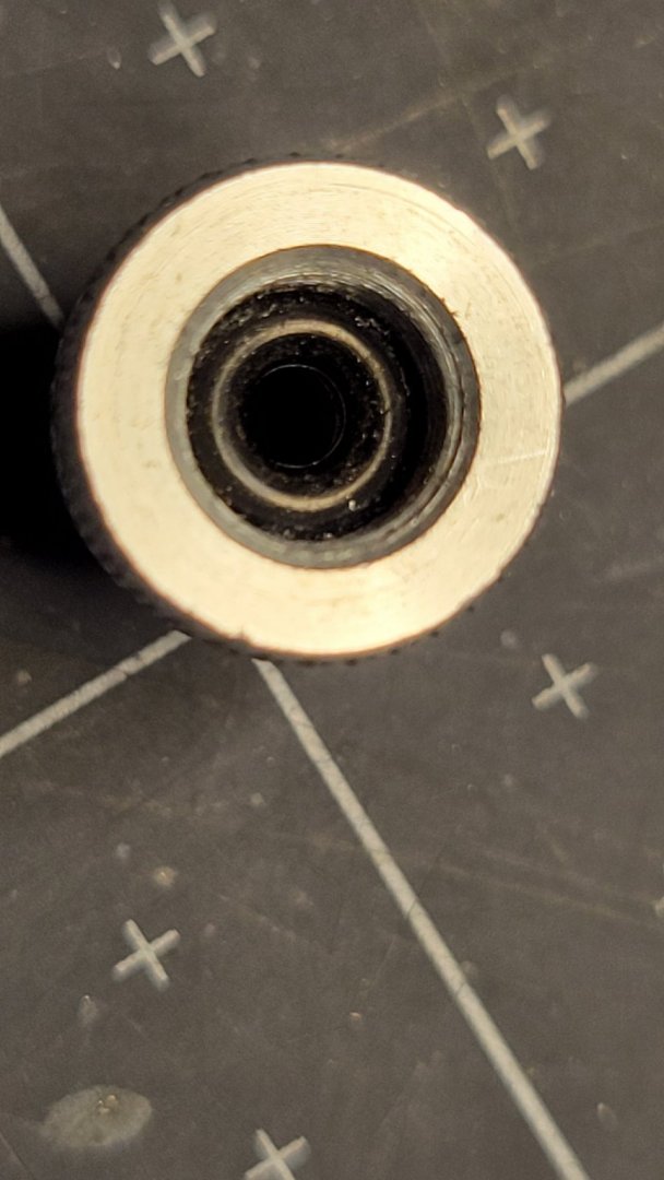
More on the airbrush. I've spent two weeks off and on fooling with this. I admit to being a novice, but the learning curve was steep. I'm finally getting nice results. There's some art to getting the paint thinned properly. The Model Expo paints I purchased are very thick and even with Tamiya thinner it's tricky to get the right consistency. It's a little more than 1:1 on the thinner. I'm still working on that. The biggest problem was the Passche airbrush. This is a quality unit but I could not get consistent results. Sometimes it would spray well other times I couldn't get the paint to flow. After much troubleshooting and reading up on the web I traced the problem to the air valve. There was very little air flow. The paint would not atomize properly. The air valve looked OK. This was a rebuildable part. I disassembled it and could find not blockage. It turned out the supplied hose adapter was the problem. This is a simple Thread reducer with a hole in it. How could that be a problem! Upon thinking about it, I realized there was an O-Ring in the end going to the airbrush. I was in the habit of tightening this all the way. What must be happening, unlikely as it seems, is the O-Ring squishes and reduces the diameter of the hole to a very small size. he cure was to not tighten the adapter all the way. I immediately got lots of air flow and the paint flowed and atomized well. The O-Ring seals well just snugged up at these low pressures. At last I can move forward with the painting!
-
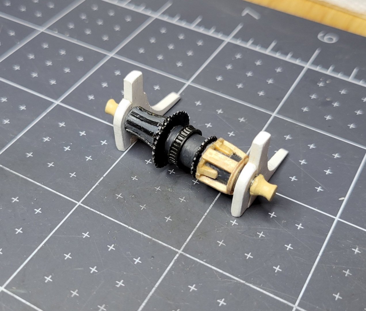
The windlass is finished. Such as it is. The deck in this area busy enough it should pass. I do wish the part was better formed. I'm having problems with the airbrushing. The new Paasche airbrush has developed an air valve problem. I'll have to get it replaced before doing more painting. I was able to get one primer coat on before it went belly up. It looks good. Wet sanding 400 grit produced a nice smooth finish. There is a suggestion of the underlying planking showing through. I feel that makes it look more realistic. In pictures of the prototype the planking shows faintly. It's ready for finish paint. Just need to get that airbrush working.