Ken_2
-
Posts
150 -
Joined
-
Last visited
Content Type
Profiles
Forums
Gallery
Events
Everything posted by Ken_2
-
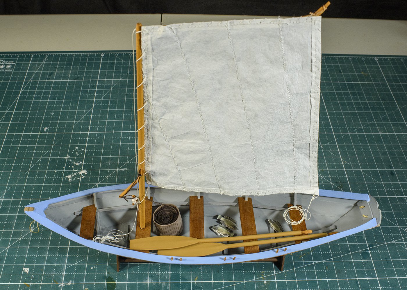
Thanks. No, the fish were not included. They were left over from another build, so I thought I would toss them in for fun ;_) I noticed I took pictures of the back side of the sail. I did a retake of the pictures with a backdrop to practice with some of my unused gear and incorrectly selected the back side. Here is my last picture (I hope) Ken
- 18 replies
-
- 5
-

-
- grand banks dory
- BlueJacket Shipcrafters
- (and 1 more)
-
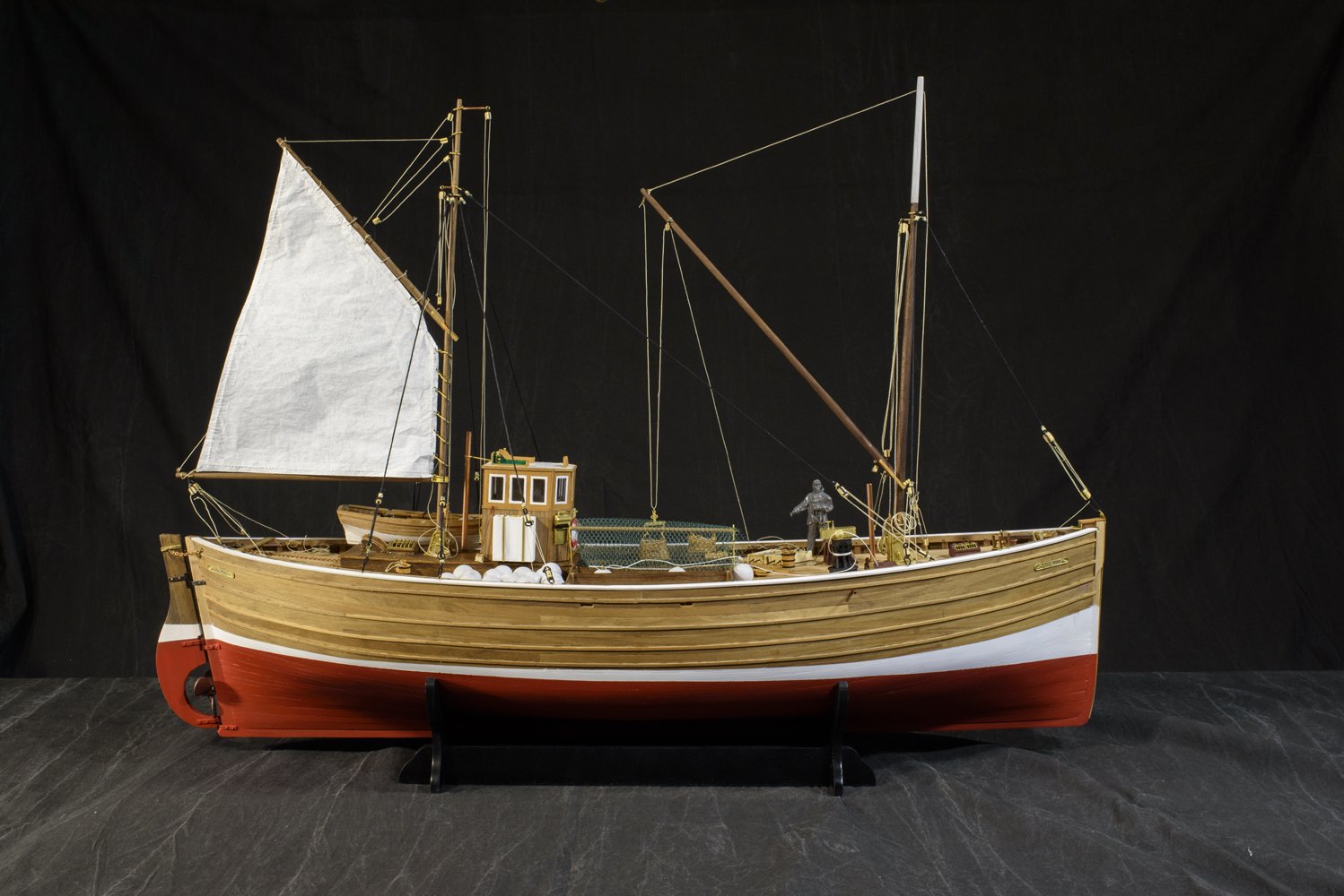
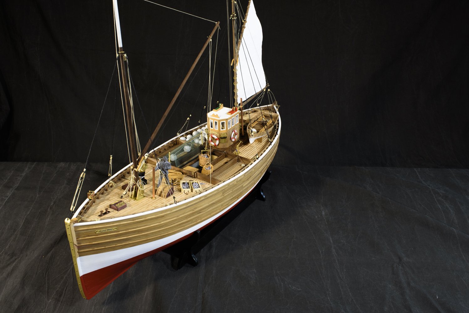
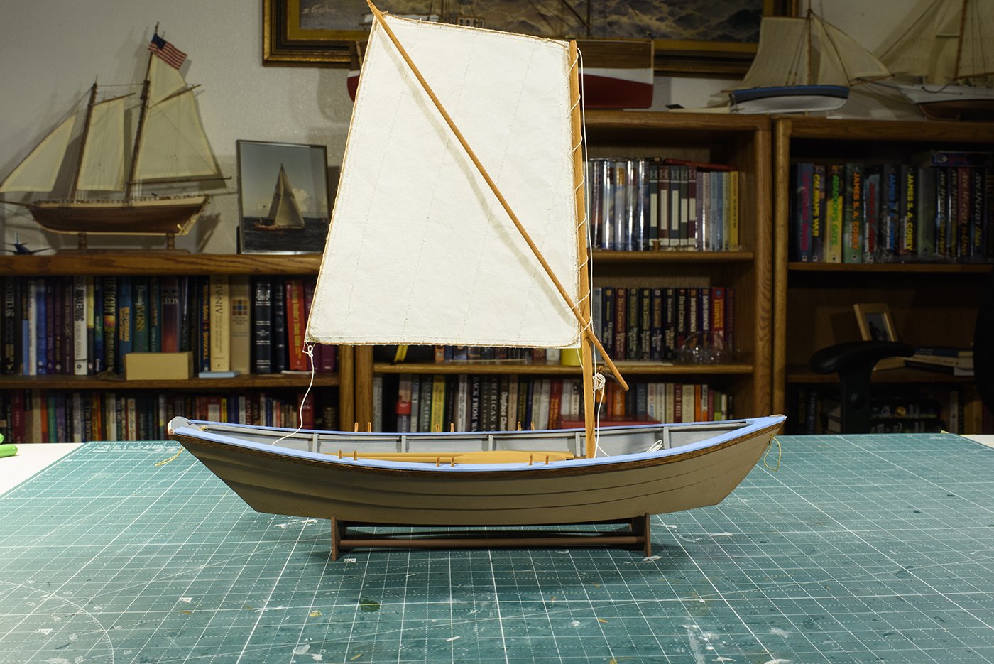
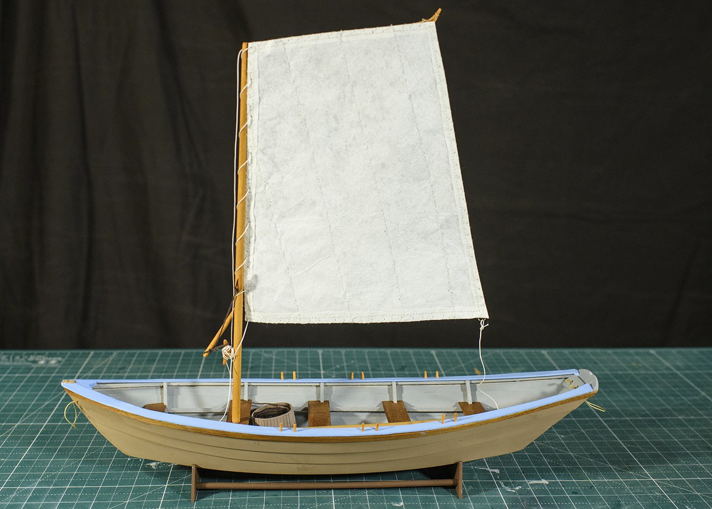
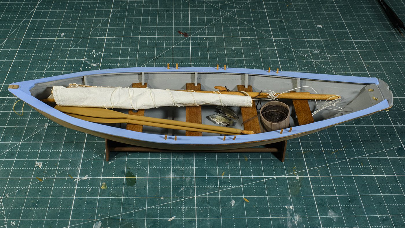
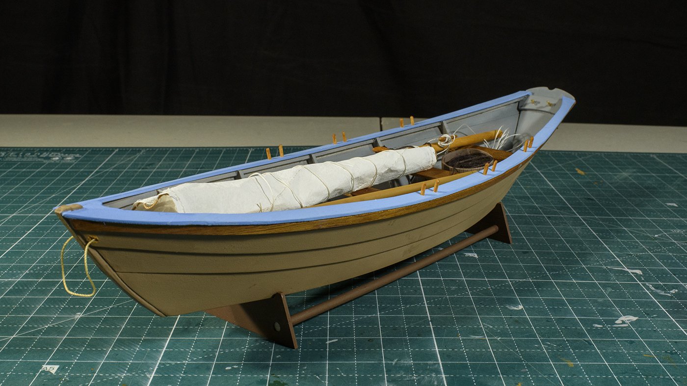
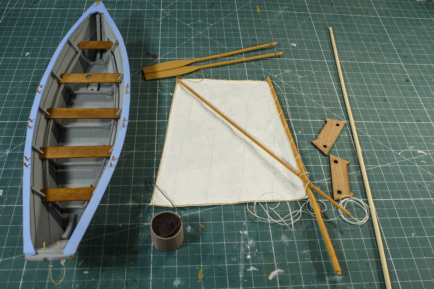
I kept thinking I was finished, but then found little items I had forgot. Add the snotter line, tie off the main halyard, and add the main sheet, and build the stand. Then I had decided to furl the sail and stow the boat on the shelf with the sail down. What do you guys think of silk span? Does it look any different/better than the kit provided cloth? I am getting better at working with it, but it does require more work. So, I guess the decision for me is if the “more work” is balance by “looks better”. Thanks for all the comments and "Thumbs up". I'll release another build log in a couple of months.
- 18 replies
-
- 8
-
-
- grand banks dory
- BlueJacket Shipcrafters
- (and 1 more)
-
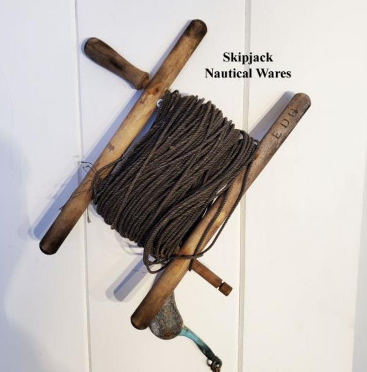
I built the line tub. I was not sure what line went in this tub. Todays fishing line is quite thin, and sit in a reel. Should I use thin sewing thread, or thick hawser? One of my friends is a fisherman so I called to ask what is was the fishing gear of the day. He sent me the following picture, so I chose my line. I’m not sure how a hook is attached to this line, but I will continue on. https://www.skipjackmarinegallery.com/antique-maine-atlantic-cod-fish-hand-line-winder-reel.html Next was to make the sails and rig the mast. My wife helped me tremendously. I have been experimenting using silk span instead of the kit provided cloth. Silk span may act and look more like sails because silk span is thinner, and folds more like a scaled down sail. The disadvantage is that it is thin paper, and tears easily. The following link is to a brief tutorial by Tom Lauria that I used. I plan to photograph the model with the sail up, and then the sail stowed, and store the boat on a shelf stowed. https://www.youtube.com/watch?v=g_m_VWzk4w8
- 18 replies
-
- 6
-

-
-
- grand banks dory
- BlueJacket Shipcrafters
- (and 1 more)
-
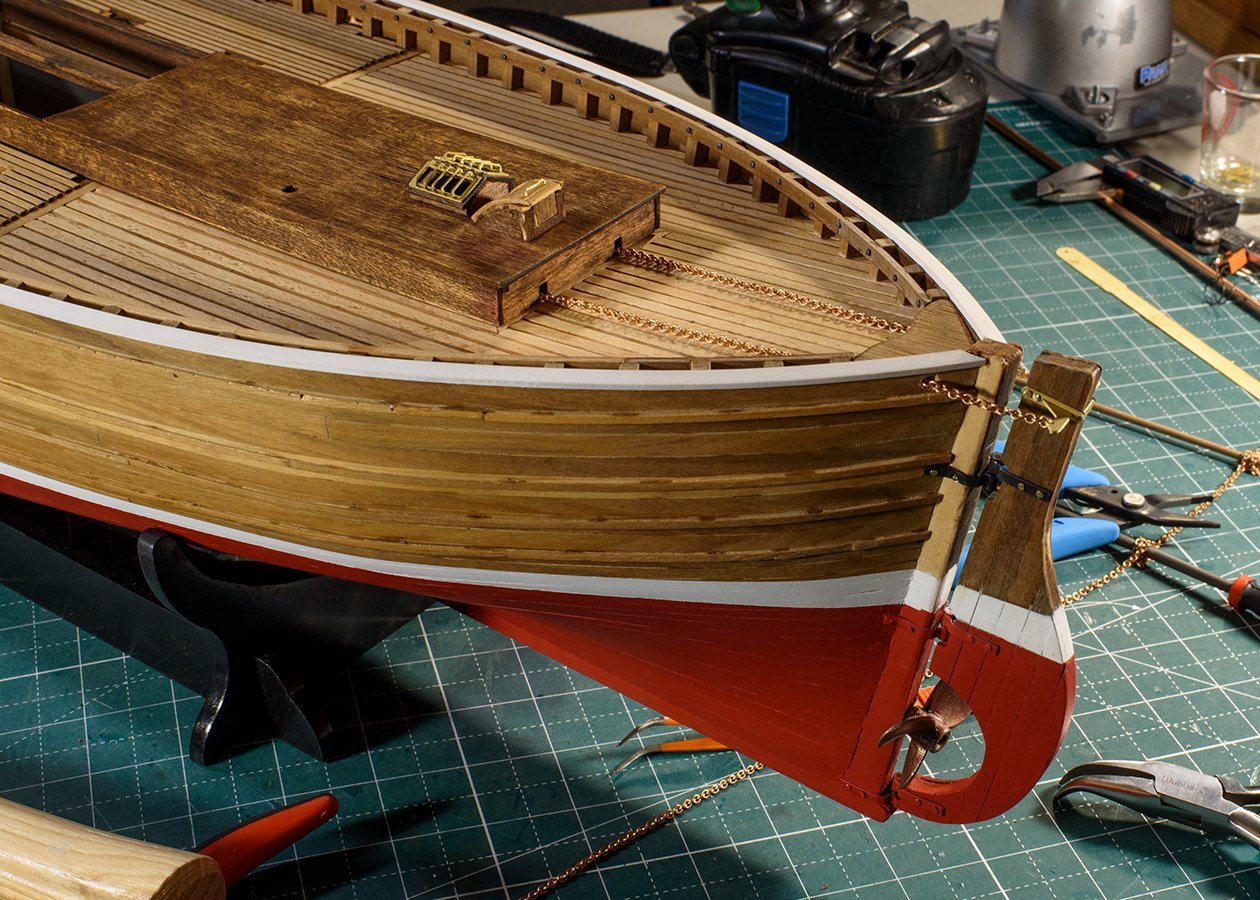
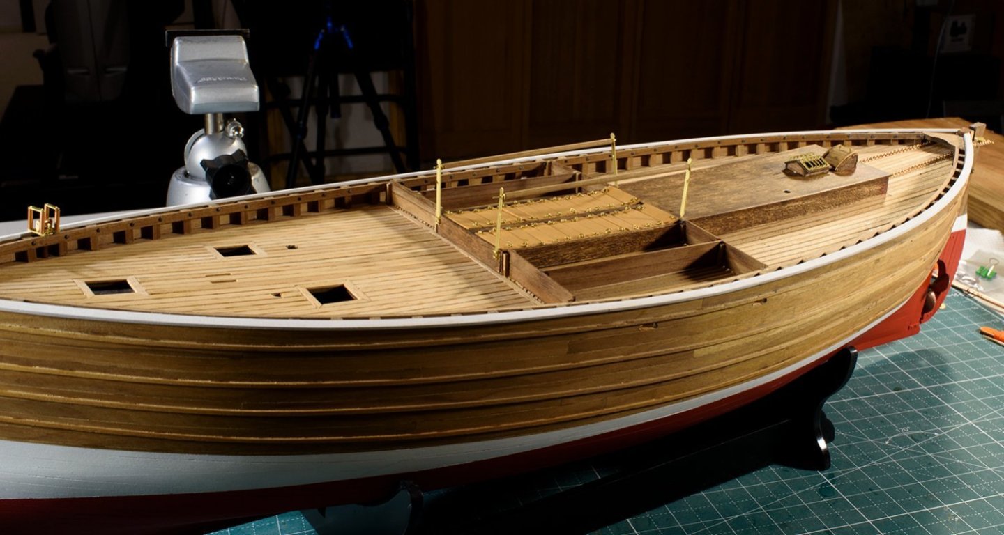
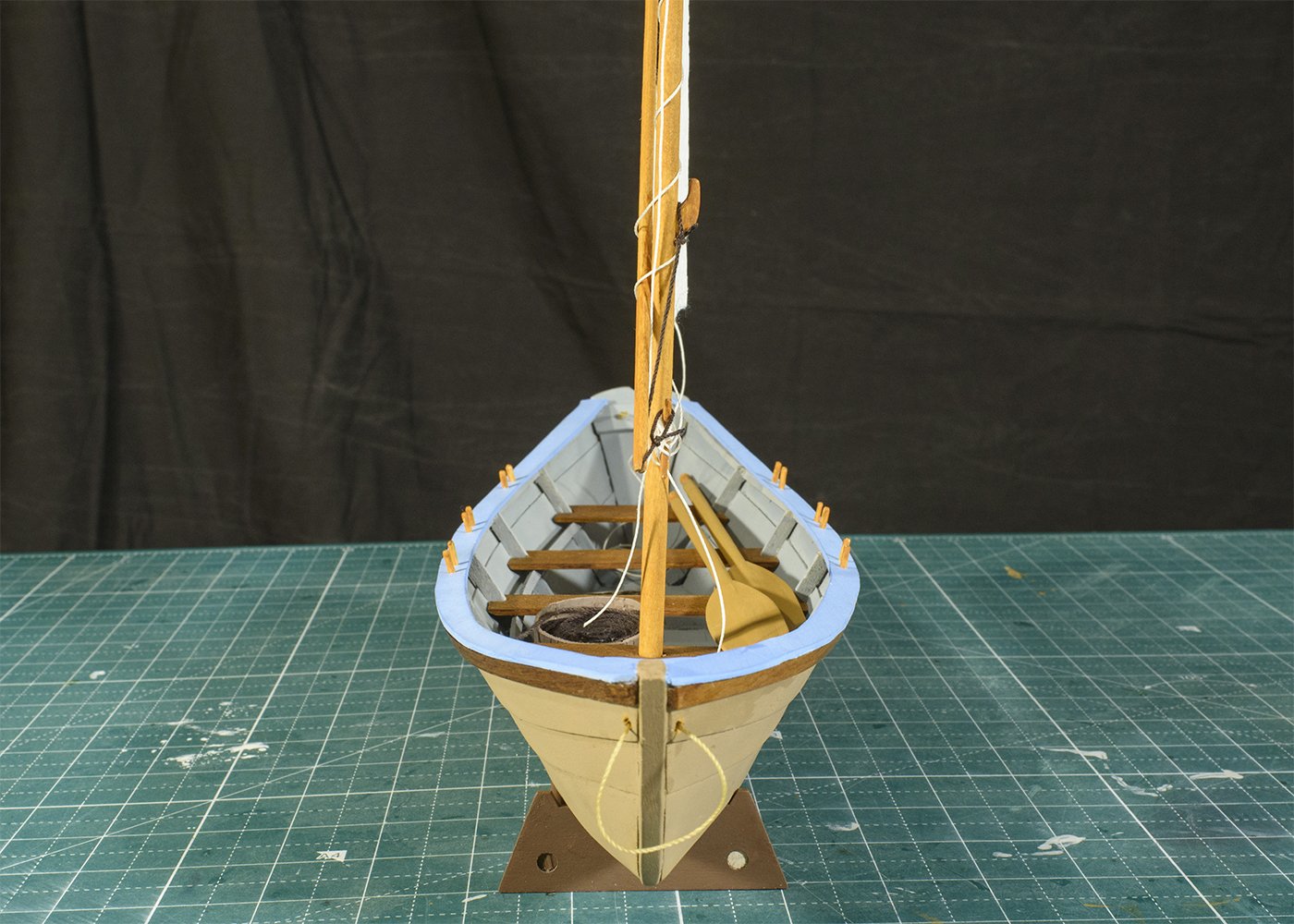
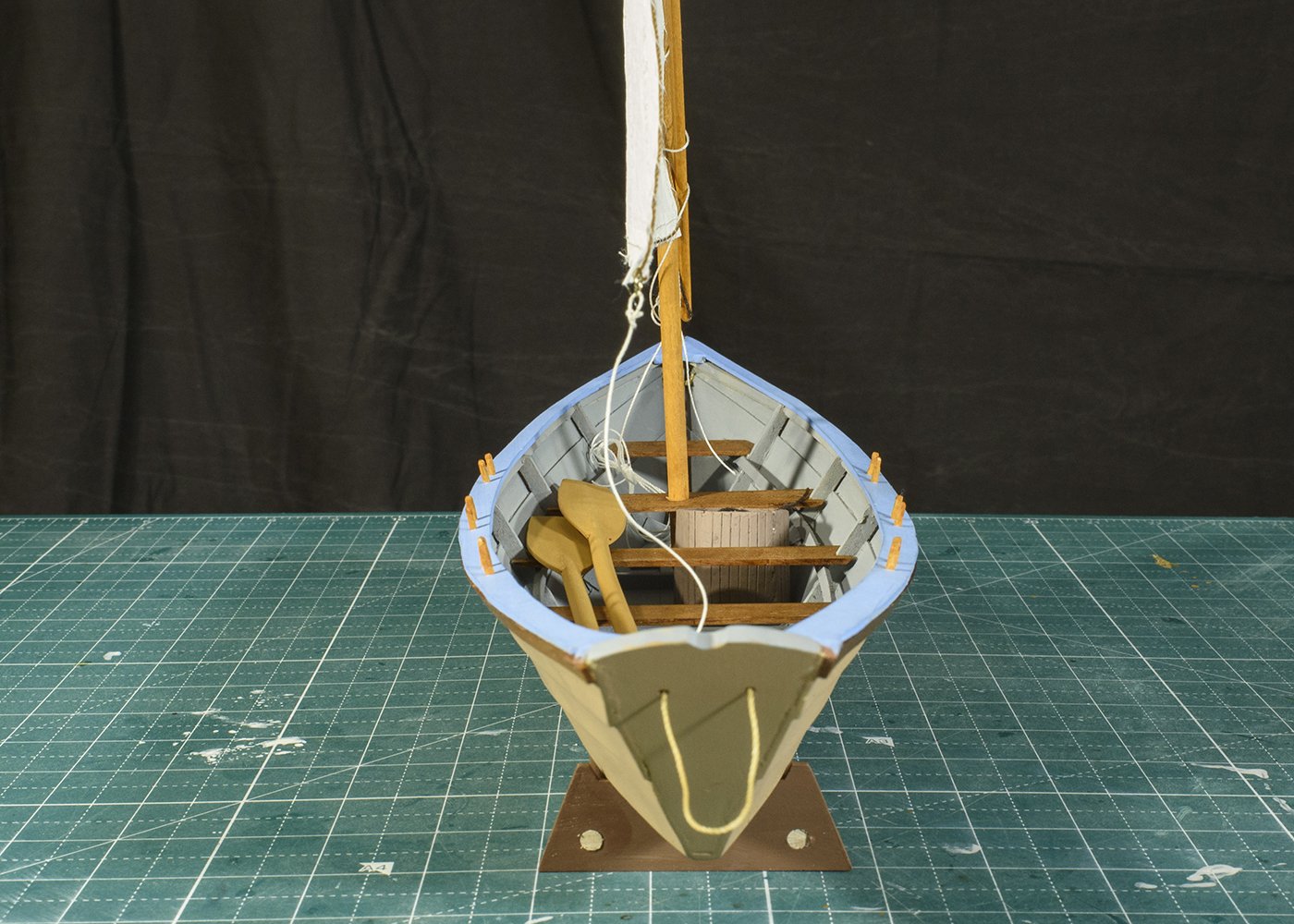
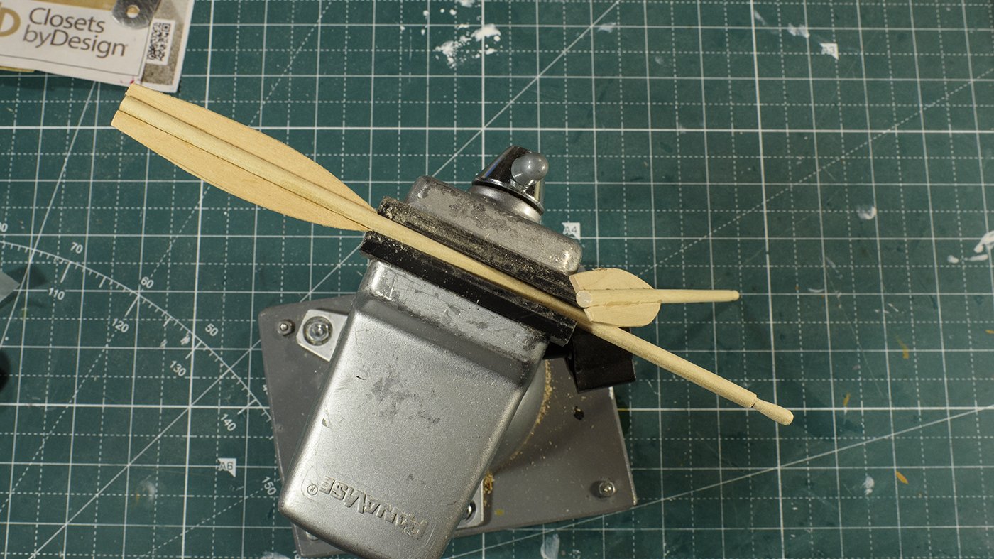
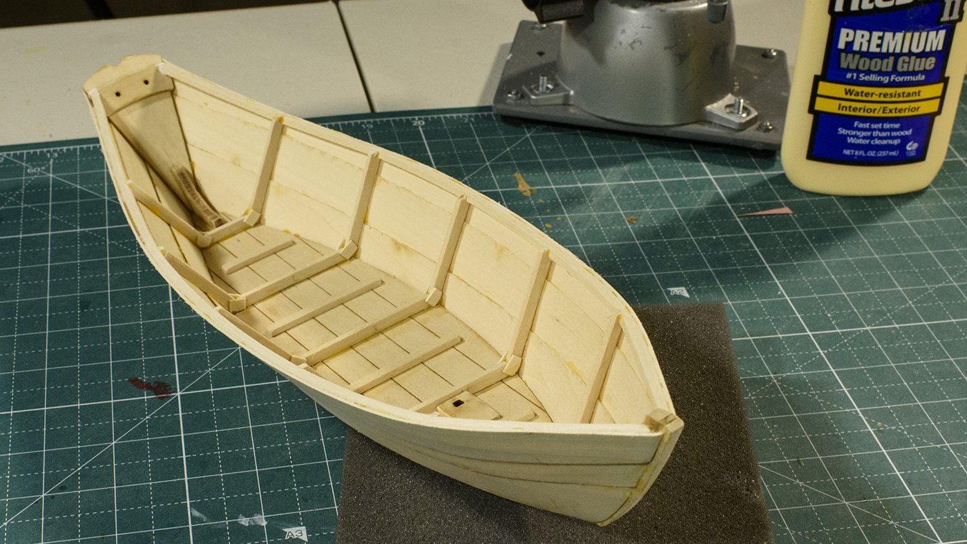
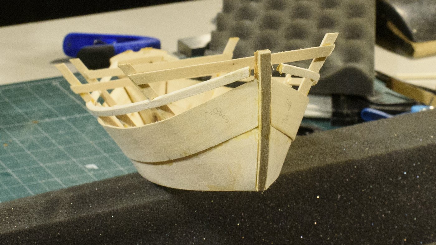
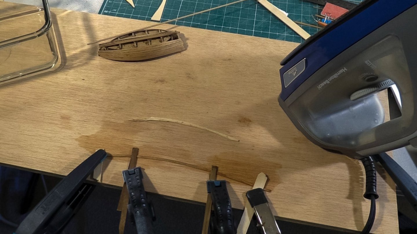
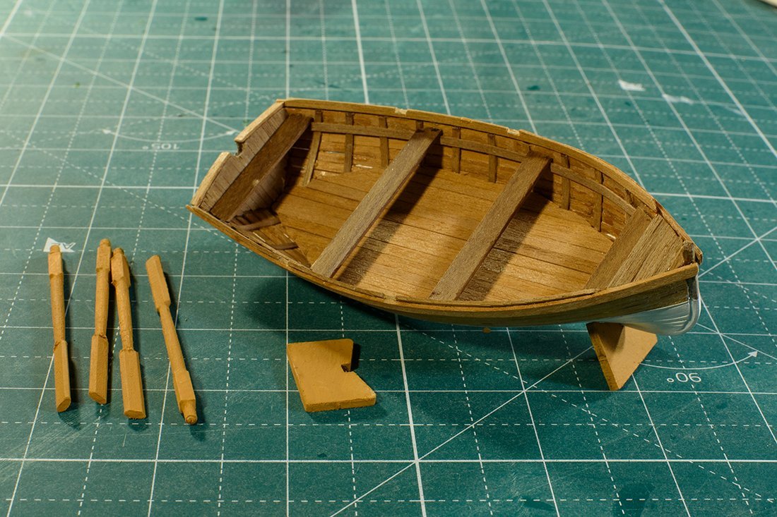
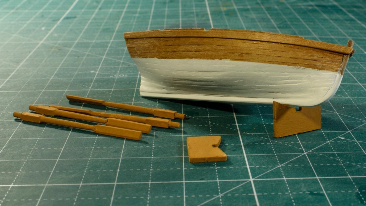
I trimmed the aft end of the sheer band, and touched up some paint flaws on the sheer band and top rail. I cut and trimmed the seats, and stained them with amber shellack. I have found that I judge the quality of my models by examining the small details. For small boats, about half the work goes into planking, but the deck equipment shows most of the details. Thus, as I near the end of a build, is where I need to slow down and be very careful, not rush to finish. An example is installing the tholes (an interesting word, the tholes being the oar locks). The drawings state to use the provided 1/16” dowel. But I could not find such a small dowel. I searched my scrap wood and found 1 short 2mm dowel (2mm slightly larger than 1/16th). I also found that toothpicks are 2 mm, so I have chosen to use toothpicks rather than use up my last 2mm dowel. I ran and experiment on which drill bit to use, what length to cut my toothpicks, and how to color them. I will use a 2mm drill bit, but I may need to pound the toothpicks into the hole (probably no glue needed). I will only drill into the cap rail, and not go as far as is shown in the drawings (I see no value in drilling into the planks). And I have selected a “raw sienna” acrylic paint diluted with some water. I tried 3 kinds of applications. 1) brush it on and wipe if off, 2) sand the wood, brush it on, let it sit, then wipe it off. And 3) brush it on and let it dry. I like option 2. After assembling one set of tholes, I notice the 5mm height of the thole above the cap rail is about equal to the 4.8mm thickness of the dowel for the oar. Oar handles of today are made from 2x6’s, which at the maximum thickness of the handle are 2” (4.8mm scales up to 2 ¼” a rather thick handle). Rather than finding a thinner dowel, I will lift the tholes to be 5.5 or 6mm high so the thick dowel will not slide off of the tholes. I will proceed with the remaining assembly using similar attention.
- 18 replies
-
- 4
-
-
- grand banks dory
- BlueJacket Shipcrafters
- (and 1 more)
-
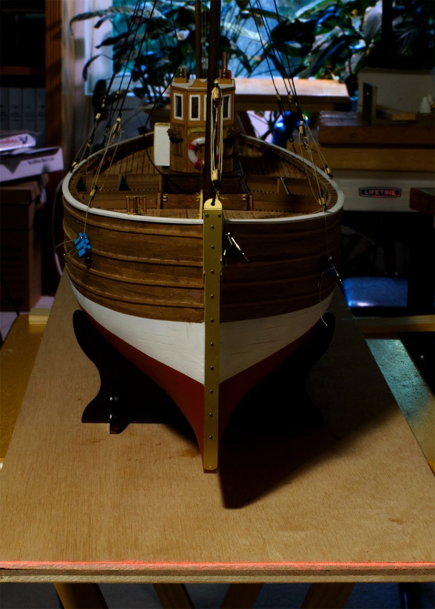
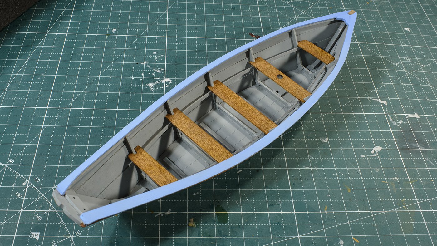
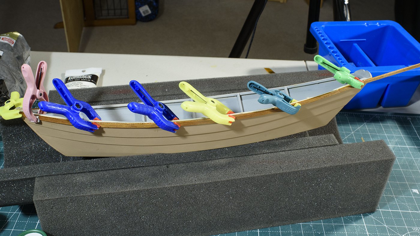
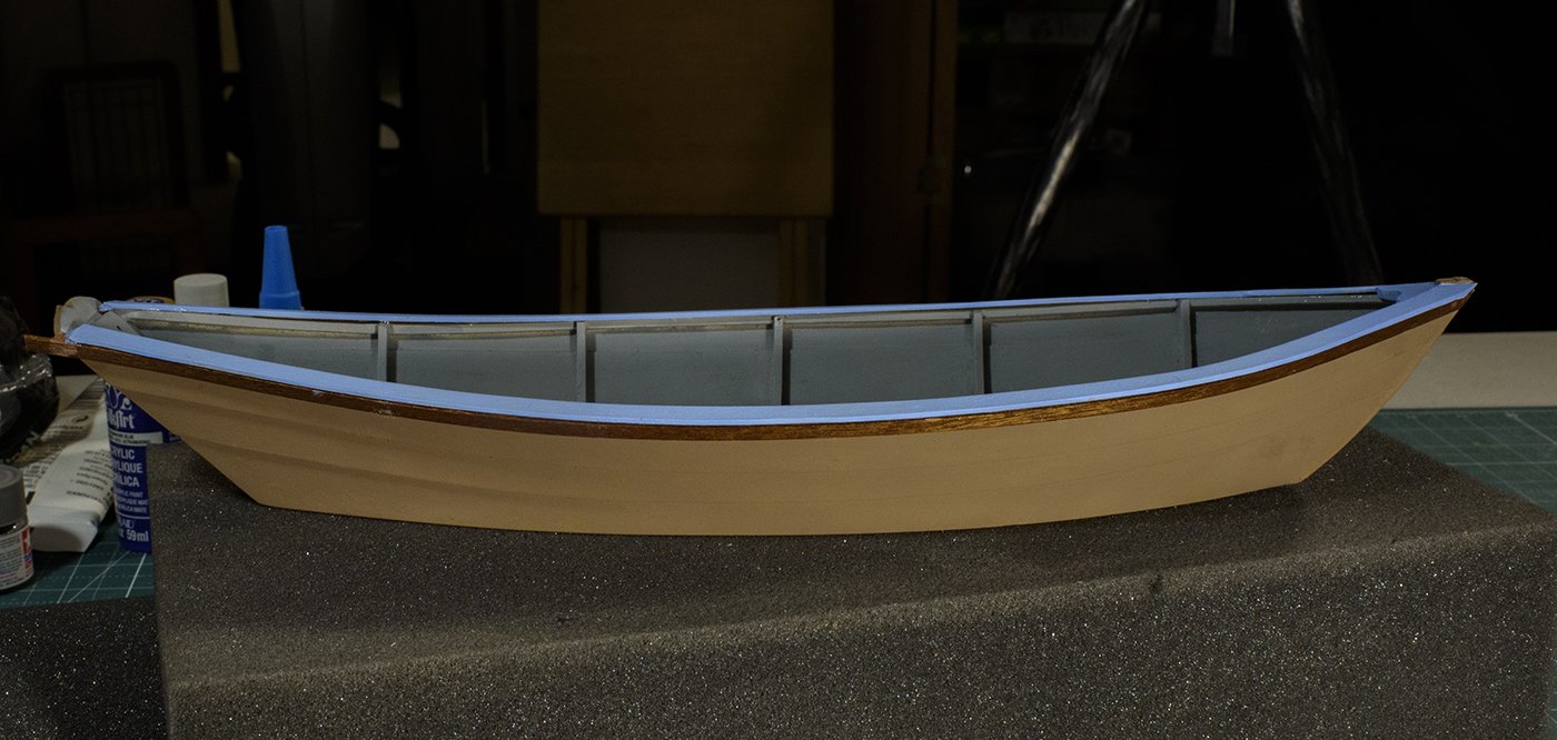
Thanks for your "likes" and comments. That makes it fun for me. It took a while to trim the one-piece cap rails. I broke one rail when I was nearly done, so I had to cut another. I could refine them some more, but I may also break them again. So, I declared victory and sealed and painted them. I’ve selected grey for the interior, tan for the hull. I used an amber shellack for the sheer band, and a light blue for the cap rail. The light blue I selected seemed very similar to the grey, so I mixed in 3 drops of a darker blue into the cup. Now I wished I used less (1 or 2 drops), as it is now a tad too blue. But not so much as to cause me to repaint it again! 🙂 I looked up the cost of paint in the northeast during the 1890's. I found the average daily wage was roughly equal to 1 gallon of blue barn paint (~$2.50). Thus, I am thinking blue is not an unreasonable expense. And I see that light blue can be found in lists of historic ships paint. Hopefully my selection of colors is not being to gaudy. There is still some pickup work to be done, e.g. the sheer band has not been terminated properly at the stern, etc.
- 18 replies
-
- 5
-
-
- grand banks dory
- BlueJacket Shipcrafters
- (and 1 more)
-
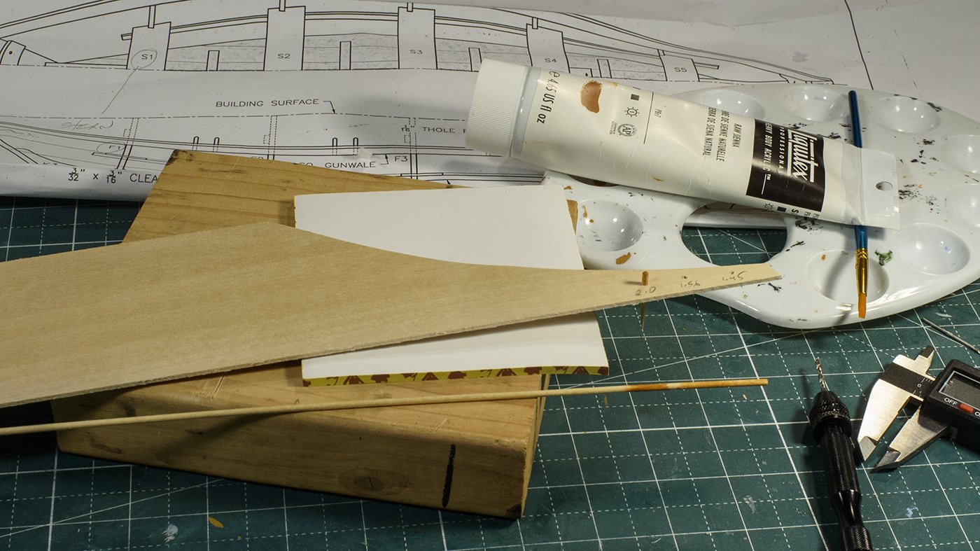
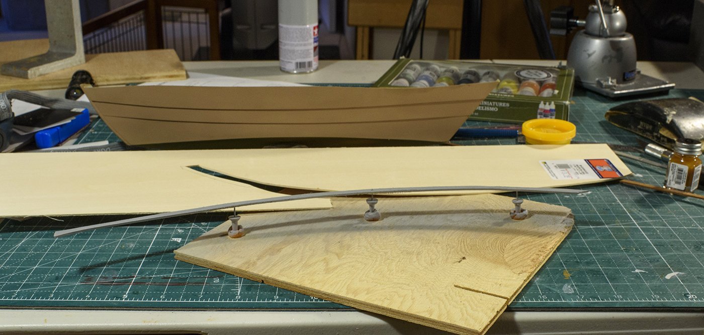
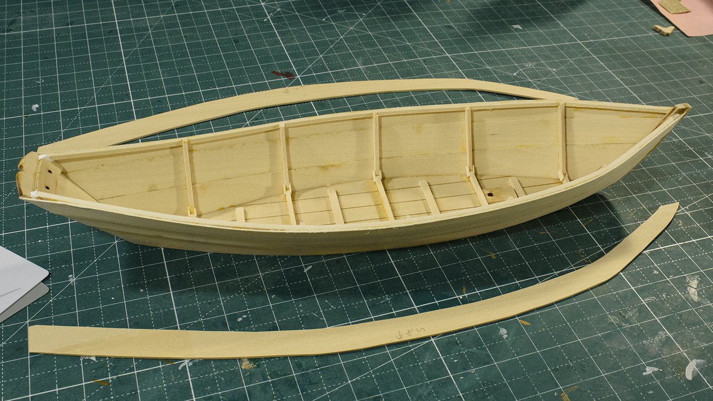
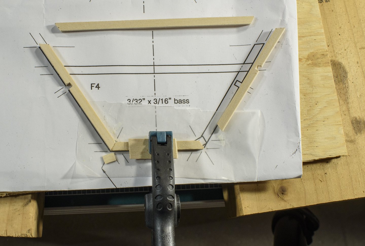
The next steps involve several interrelated components: 1) the leveling of the wale 2) installing and trimming the top plank to a leveled wale, 3) Installation of the breast hook, 4) Making the cap rail so it fits the shape of the boat 5) The installation of the cap rail, 6) install the mahogany sheer bands and 7) think about the colors of each of these parts. Whoa! Ive been down this road before. I have found it is best to figure out the color scheme and paint the pieces (if they are different colors) before they are assembled! Thanks to the build log of “East Ender”, who pointed out how the top of the wale should be flat wrt the waterline. The long square wood for the wale is crooked due to being twisted in board and up at the bow and stern, while also out and lower down at the beam (see previous picture). Thus, I sanded it flat, and then installed the 3rd plank. I then trimmed the top the plank to be even with the wale. The cap rail is to sit on top of the wale and plank and join somehow with the sheer band. The kit provides some short sheet wood and instructs us to cut 3 different segments to make one cap rail. I thought this was doable, but may be more difficult than making one long piece for each side. I had a large sheet of 1/16” bass wood, so I made my first rough cut. I will continue to refine this as I go along. Now is the time to think about colors before installation of the cap rail. Let me give this some thought.
- 18 replies
-
- 6
-
-
- grand banks dory
- BlueJacket Shipcrafters
- (and 1 more)
-
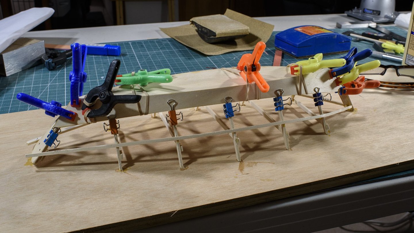
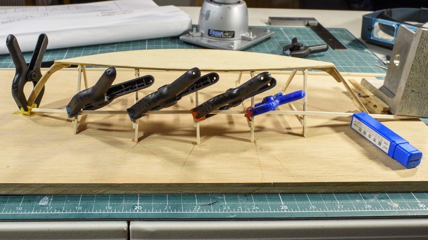
As I prepared for the 2nd plank it became clear it would be difficult to clamp it down during the glue set phase if the boat remained upside down on the board. So it is time to remove the boat from the board. The first 2nd plank went on OK, but the other 2nd plank needed to be symmetrical to the first one, which was a bit of a chore. The instructions stated the 2nd plank should overlap the garboard plank 1/16”. With the wood all slippery with wood glue, and I have only 2 hands and a few well placed clamps, I had a hard time getting the port 2nd plank to align with the starboard 2nd plank, (both fore and aft and in the middle and 1/16th” above the garboard). After a while I got it, but it seems I broke a few of the frames. It turns out we have to cut them off anyway, but it would have been nice to have cut them smooth rather than the rough break. As I wrestled with these planks, I notice the forward part of the gun wale looked wonky. First, there were gobs of dried wood glue holding the gunwale to the stem in an uneven fashion. So, with a little acetone I cleaned up the glue and I am preparing to re-attach the forward part of the gunwale; a little higher and more symmetrical.
- 18 replies
-
- 5
-
-
- grand banks dory
- BlueJacket Shipcrafters
- (and 1 more)
-
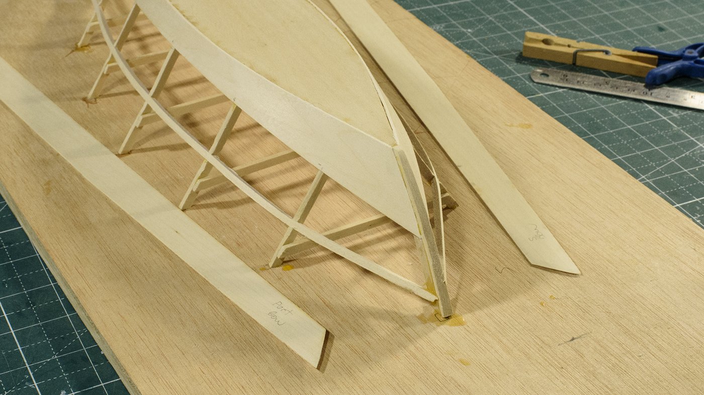
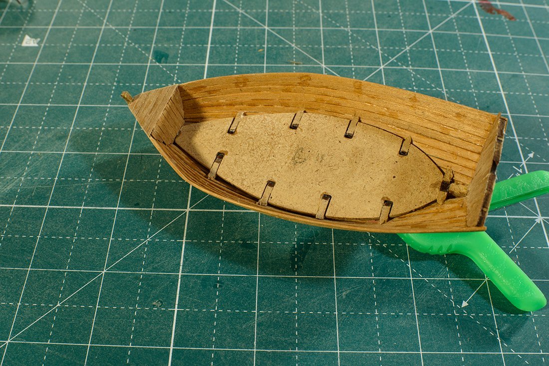
After both gunwale strips had dried, I glued them in place. Next, I soaked, bent, and installed the gripe. I could not decide how I wanted to terminate planks at the bow. There were pictures that depicted the planks terminating on the stem and other pictures that depicted on the gripe. After study, I chose to terminate the planks on the gripe. I sanded the frames to create a mating surface for the plank. I installed the garboard plank and let it dry overnight, as seem below. To get the bow and stern to align required that some of the plank overhang the bottom and stern. I will remove all the clamps and sand the plank smooth. If I like the “look” of the plank installation, I will install the starboard plank and maybe the 2nd set of planks. I will eventually need to sand a quarter of the gunwale down since it sticks out. And then remove the assembly from the board. It will be easier to terminate the gunwale onto the transom.

- 18 replies
-
- 5
-
-
- grand banks dory
- BlueJacket Shipcrafters
- (and 1 more)
-
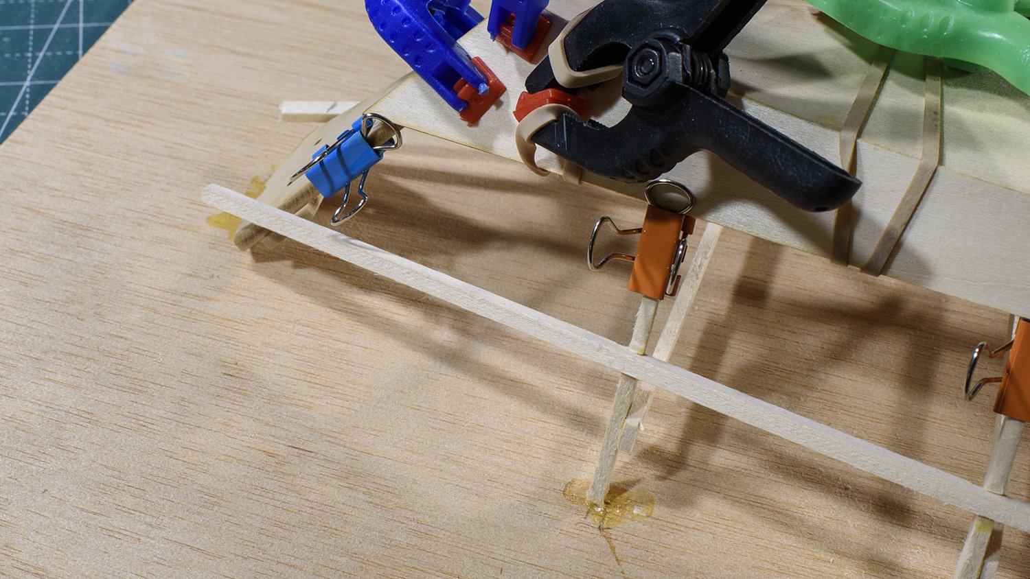
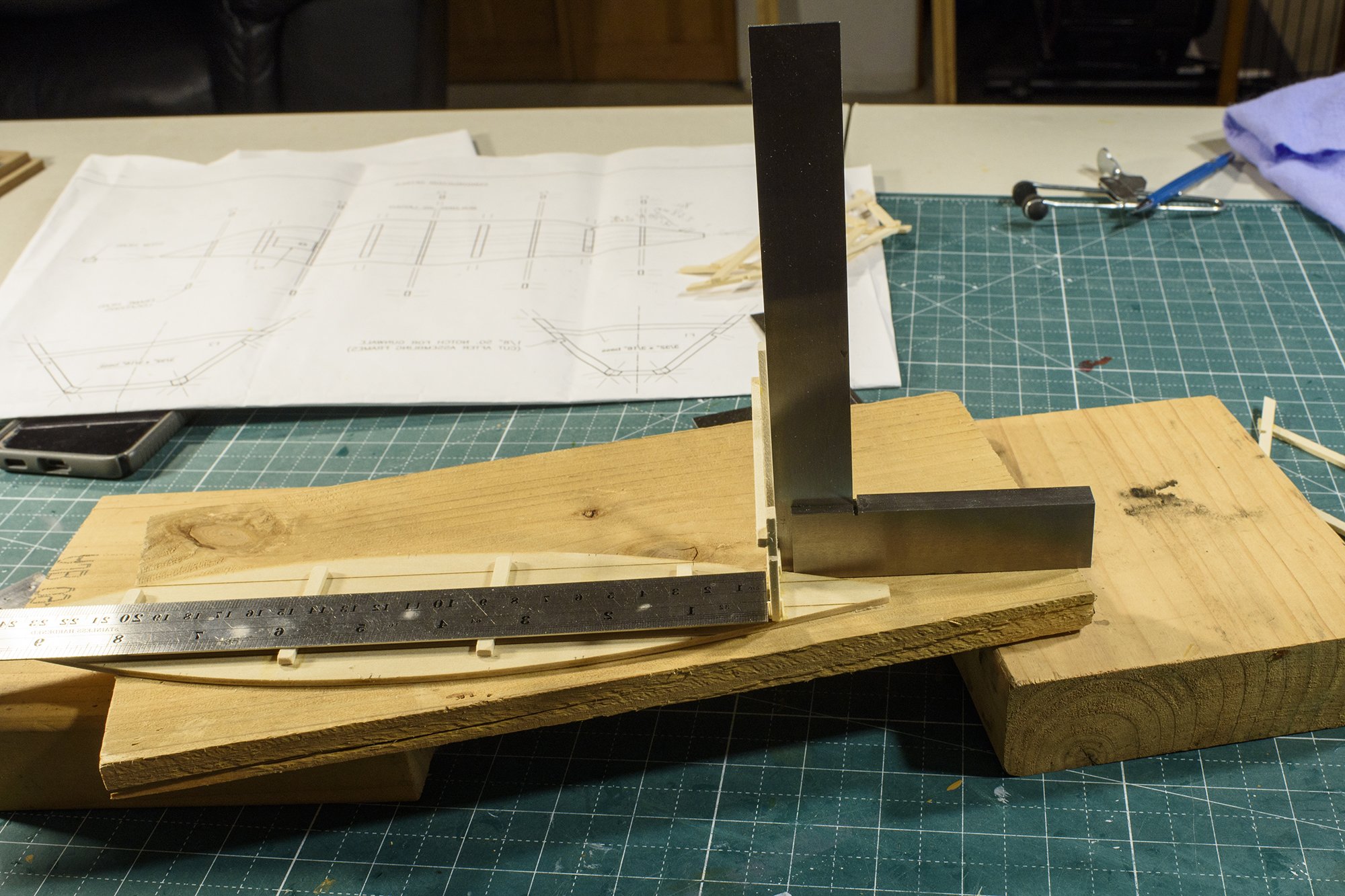
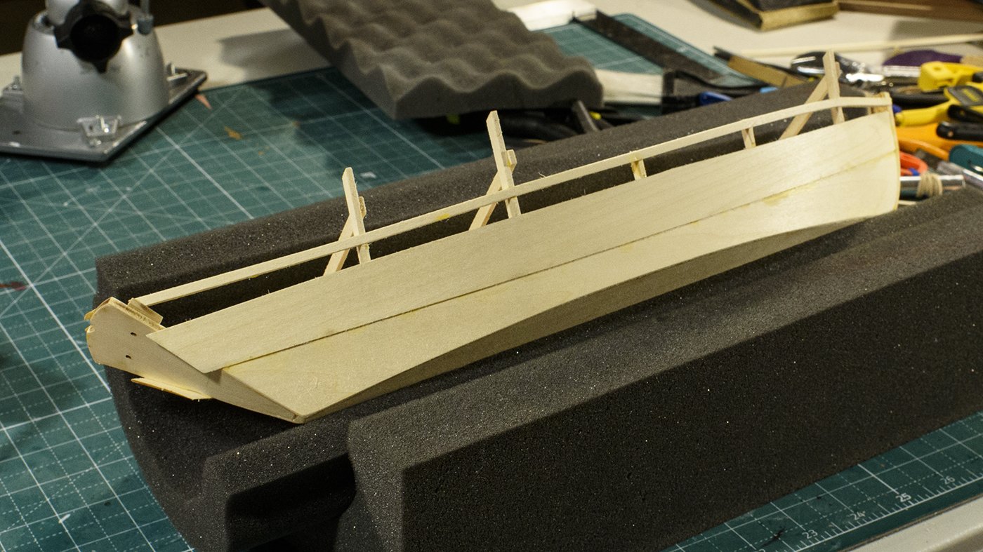
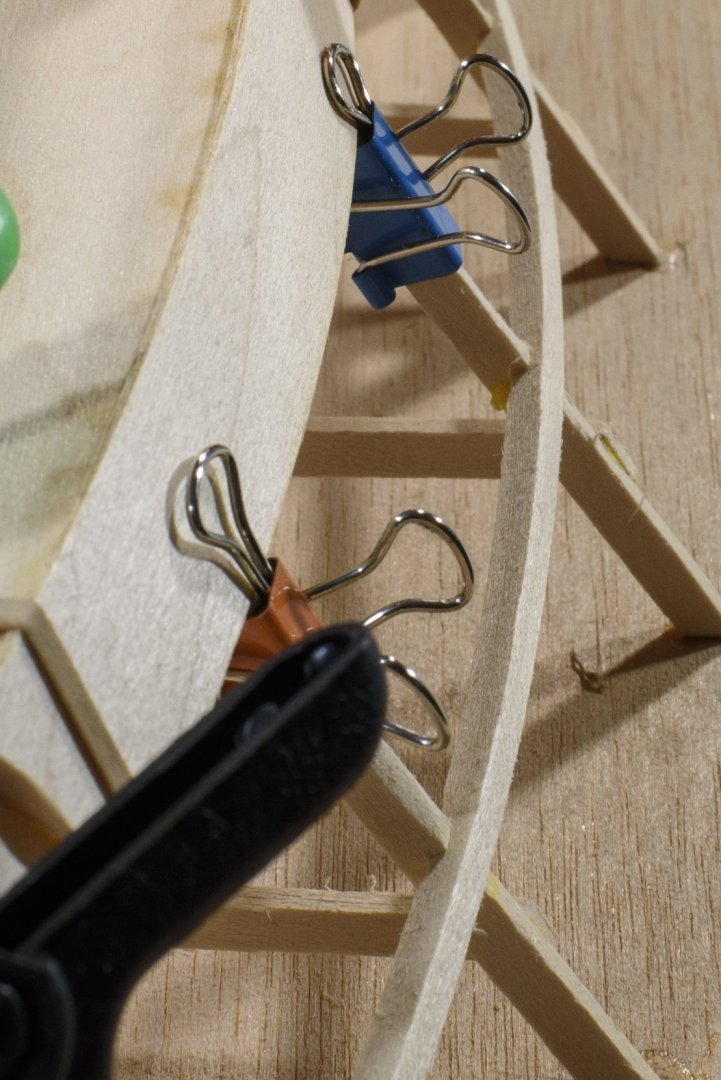
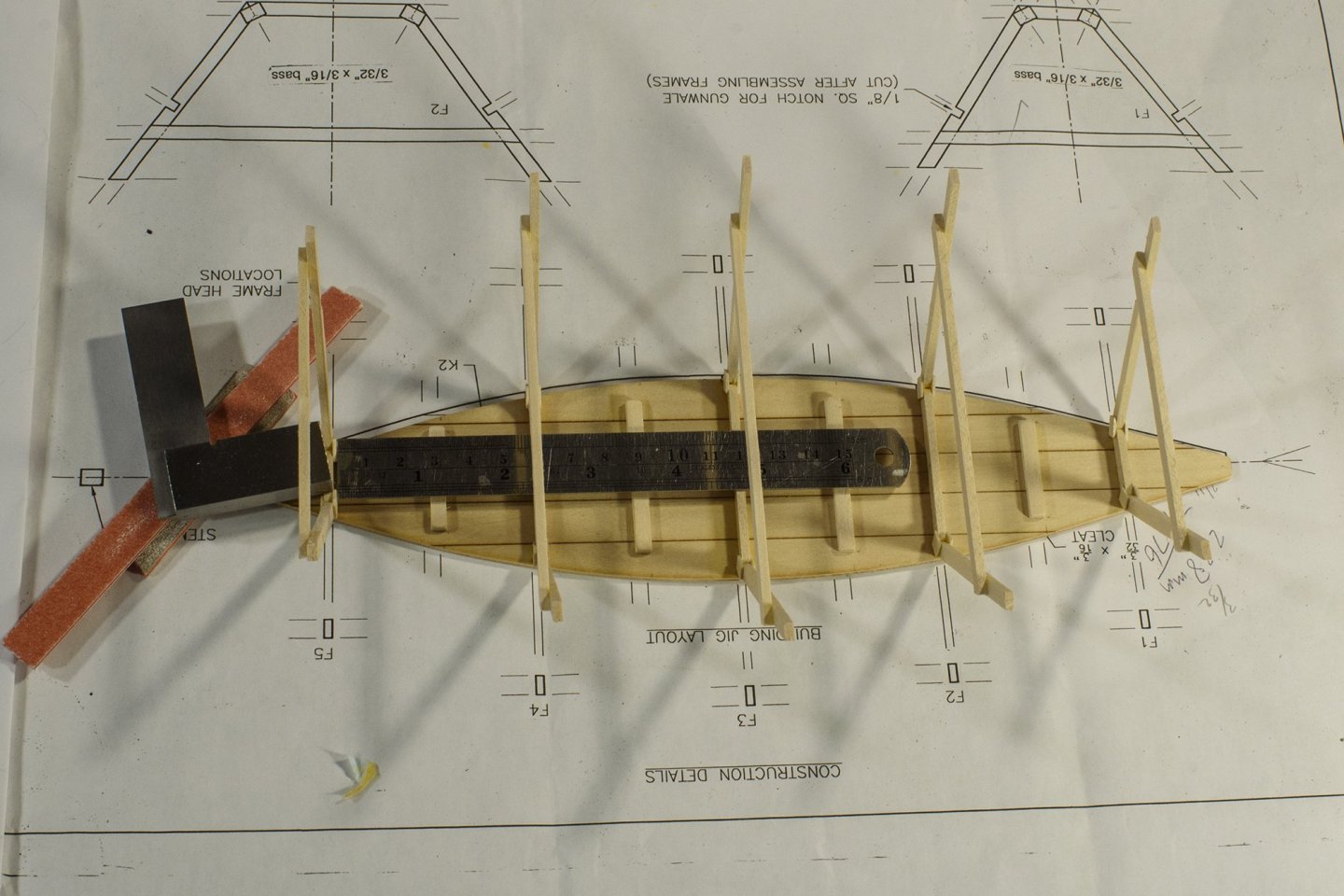
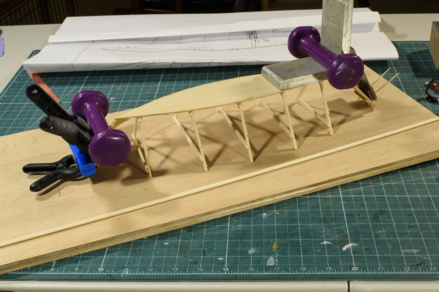
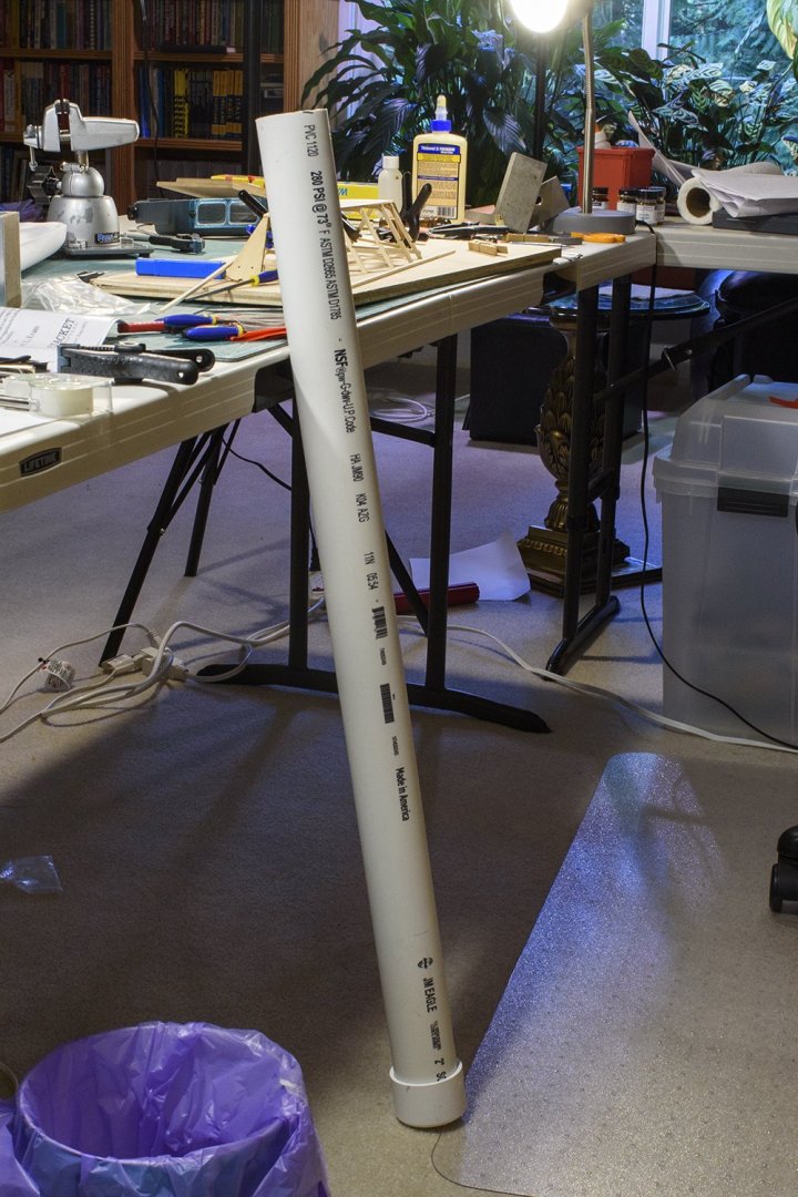
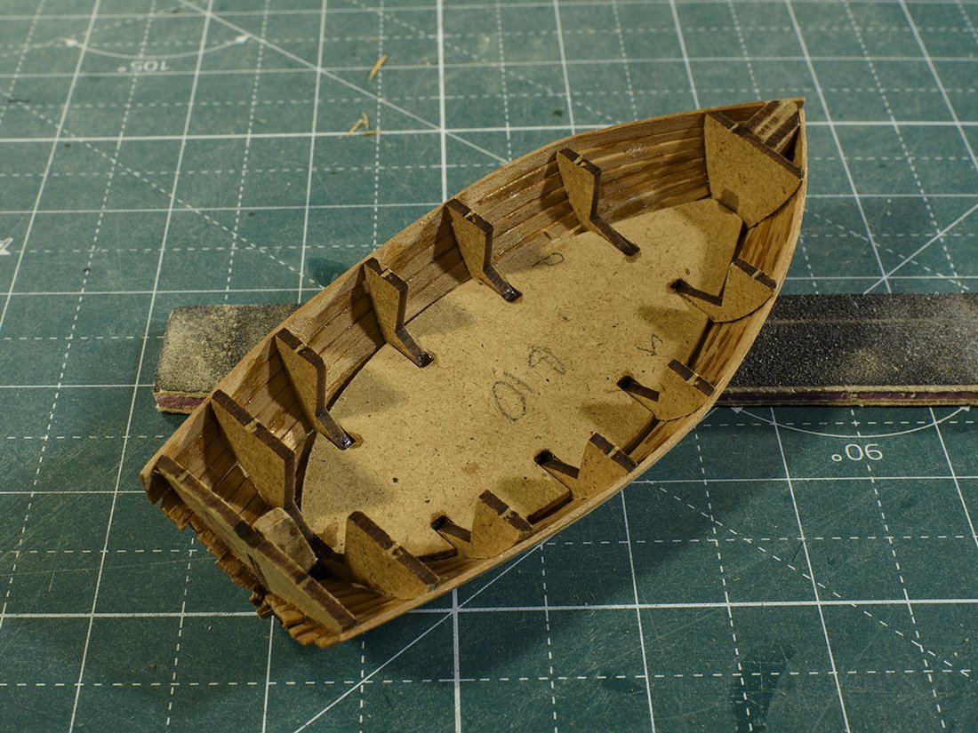
I put pencil marks on the bottom where the frame are to be placed. I started gluing the frames onto the bottom with clamps. However, even my smaller clamps would put enough pressure on the frame to cause it to slide, just a bit. So, I eventually changed my process to place glue on the frame, set it on the boat and I used a machinist square to ensure the frame was vertical and a ruler to ensure the frame was square athwartships. Once aligned, I used another machinist square to provide weight on the frame as it dried. I then inverted the assembly and glued it to a board. The bow and stern did not touch the board, due to the shear of the boat, I used 1 lb pound weights to hold the frames to the board overnight and let the glue dry overnight. I dry fit the gunwale wood in each slot and found I had used too small a square file for the slots. I carefully enlarged the slots. I spent some time on locating where I would start and terminate the gunwale. I then soaked the Gunwale wood in hot water. The wood was too long so soak in any of my pans, so I used a PVC pipe I have for long pieces of wood. I then placed the wet wood at the bow, and in each slot and along the stern, clamped it, and let it dry.

- 18 replies
-
- 5
-
-
- grand banks dory
- BlueJacket Shipcrafters
- (and 1 more)
-
I cut the 4 “cleats” and glued them to the bottom of the boat. Next, I cut the 4 pieces of the first frame along with the 4 frame plates. The instructions state to use the drawing as an assembly guide for gluing but cover the drawing with waxed paper so the dried glue does not damage the drawing. I found that these small pieces of wood moved a lot when handling. This made for in-accurate marking and cutting of the wood so that the glued assembly was not “square”. I elevated the drawing and wood onto a thin piece of plywood. This was placed over a pair of 2x6’s. I then clamped the base piece of the frame to the drawing and plywood which resulted in no more movement. I found the cuts were far closer to true and the glued assembly far more “square”. I finished the 5 frames in this manner. Next I will glue the 5 frames, stem, knee mast and transom assembly to the bottom. This will be a test to see how well I followed directions!
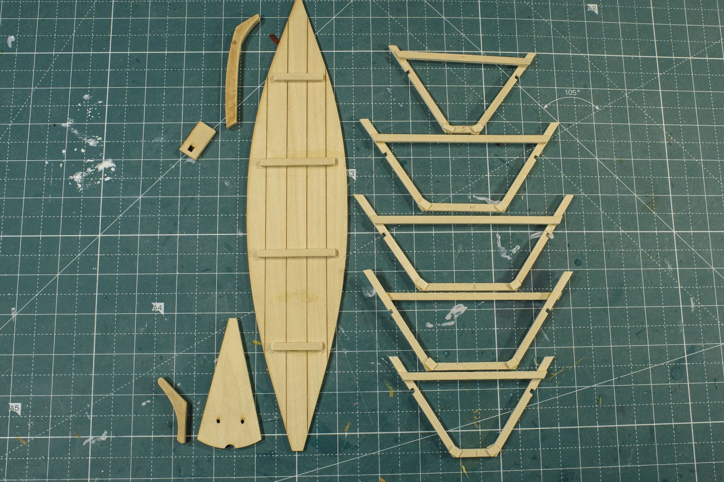
- 18 replies
-
- 4
-
-
- grand banks dory
- BlueJacket Shipcrafters
- (and 1 more)
-
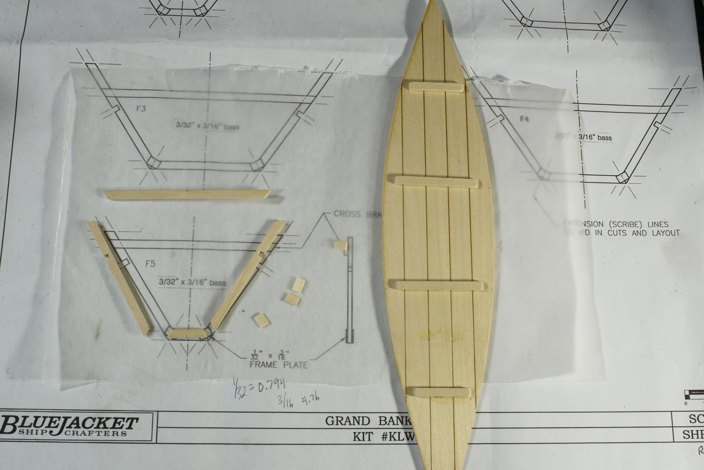
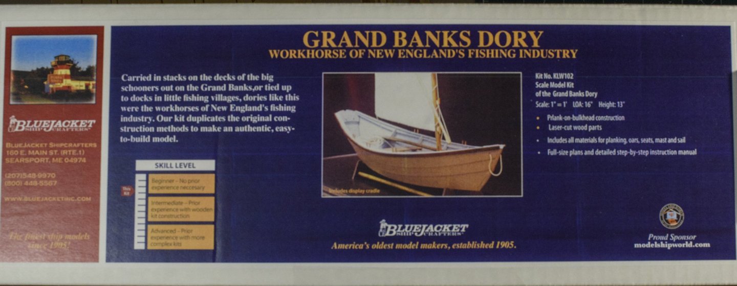
The Banks dory is a small, open, narrow, flat-bottomed, and slab-sided boat with a particularly narrow transom. These boats were inexpensive to build and could be stacked or nested inside each other and stored on the decks of larger fishing vessels which functioned as mother ships. Banks dories have long overhangs at the bow and stern which helps them lift over waves. Most could be fitted with sails. The dories became more stable when they were loaded with about half a ton of catch. Back to the subject: the Kit itself looks like a quality set of components. I also purchased the recommended paint kit, which will save me time. Getting the enamel paint does not take too long. However, for me, I stress over what colors I should use, and choosing takes a lot of time and research, so I purchased the addition of the paint kit. I reviewed the other Build Logs for tips and tricks and found lots of good advice. From the instructions, I identified the first task. I cutout those pieces of wood which are involved and sanded off most of the laser char.
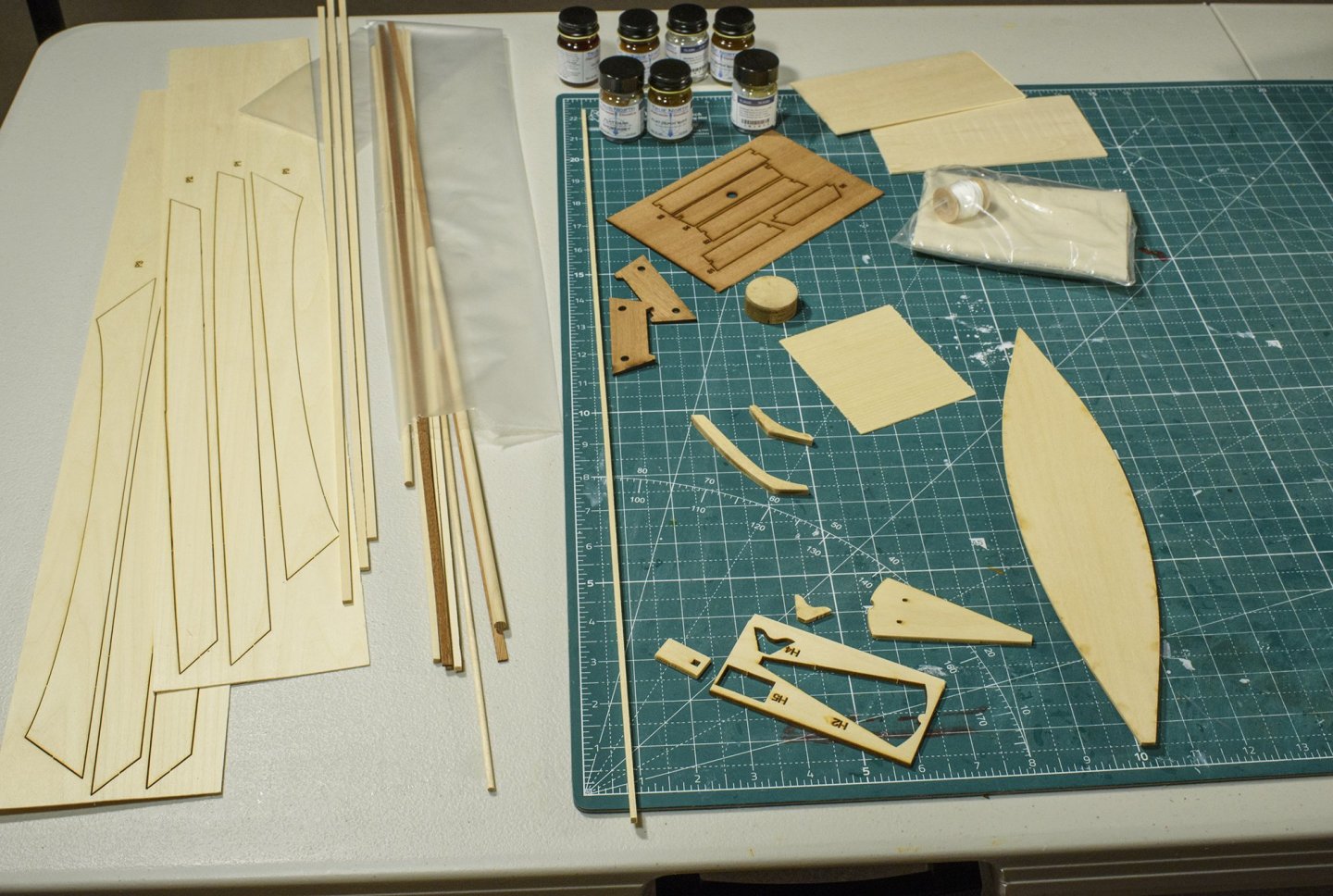
- 18 replies
-
- 5
-
-
- grand banks dory
- BlueJacket Shipcrafters
- (and 1 more)
-
Your workmanship is great, and your boat looks very nice. Ken
-
I too, am viewing your build after you are completed. I like your pictures and your explanations as you build. And your resultant boat looks very nice. Good luck on building your full-size boat! Maybe you could add a few pictures to this log as you progress on your full-size boat or add a link to where you are documenting the build. Ken
-
Thanks all for your encouragement. That is very kind. As Dsmith points out, I do have a YouTube channel with this very build, if you are interested.
-
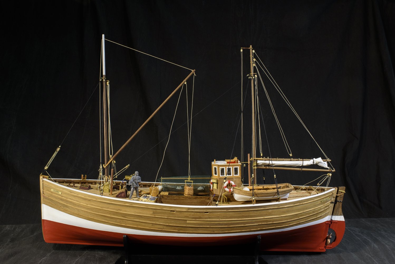
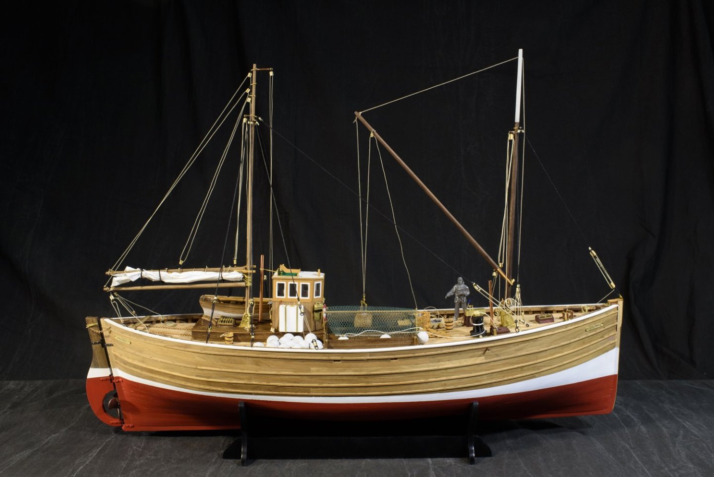
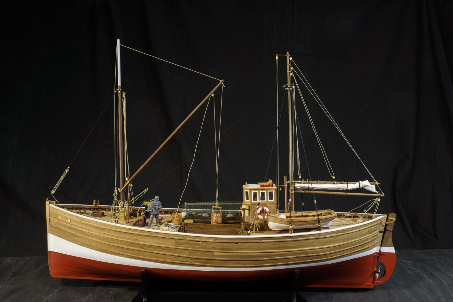
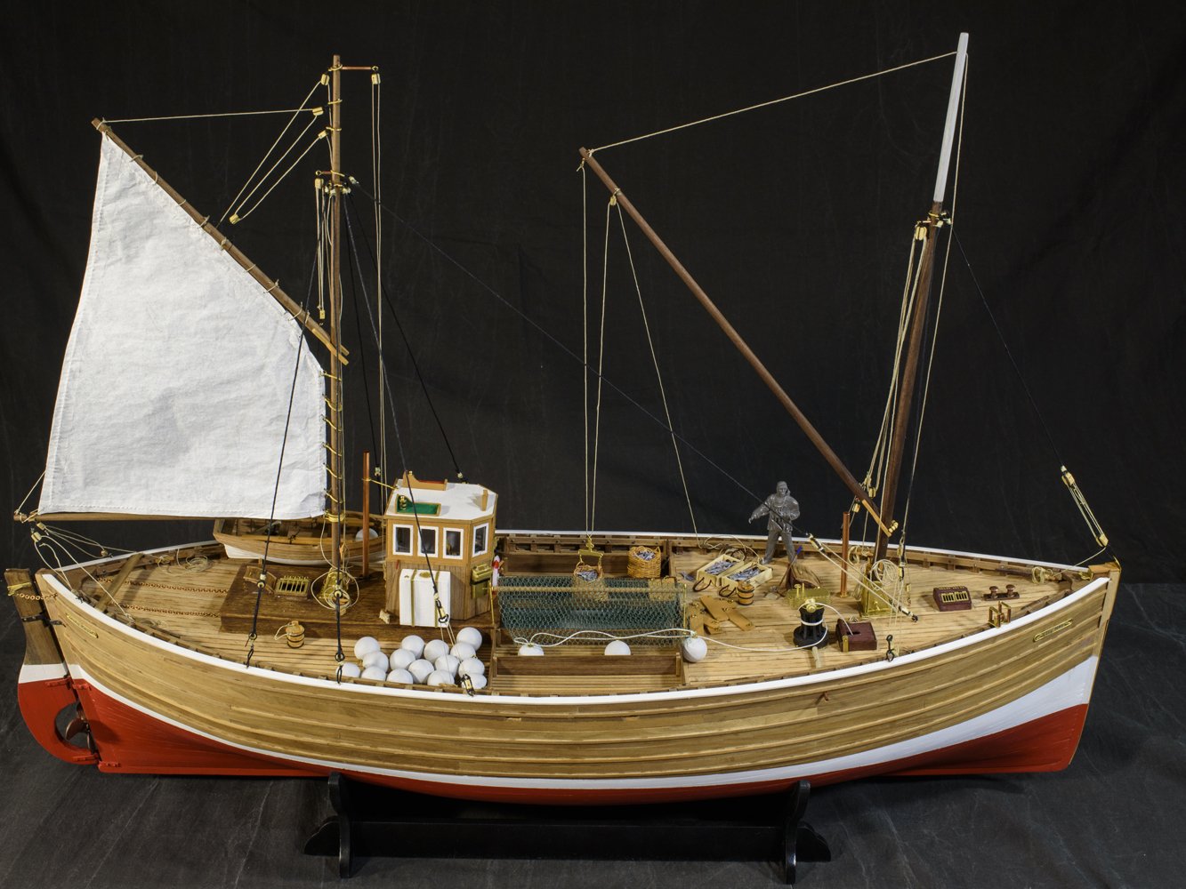
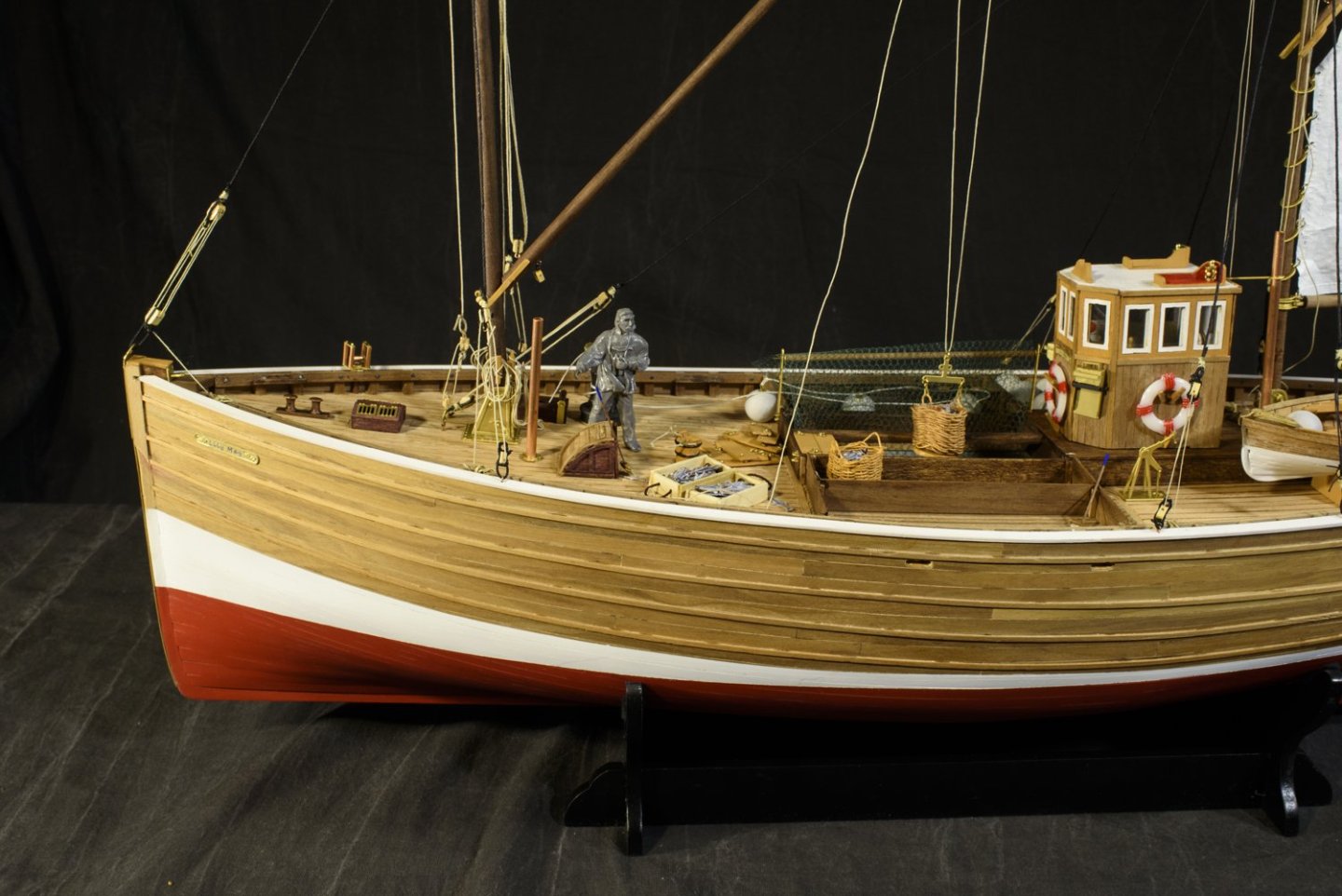
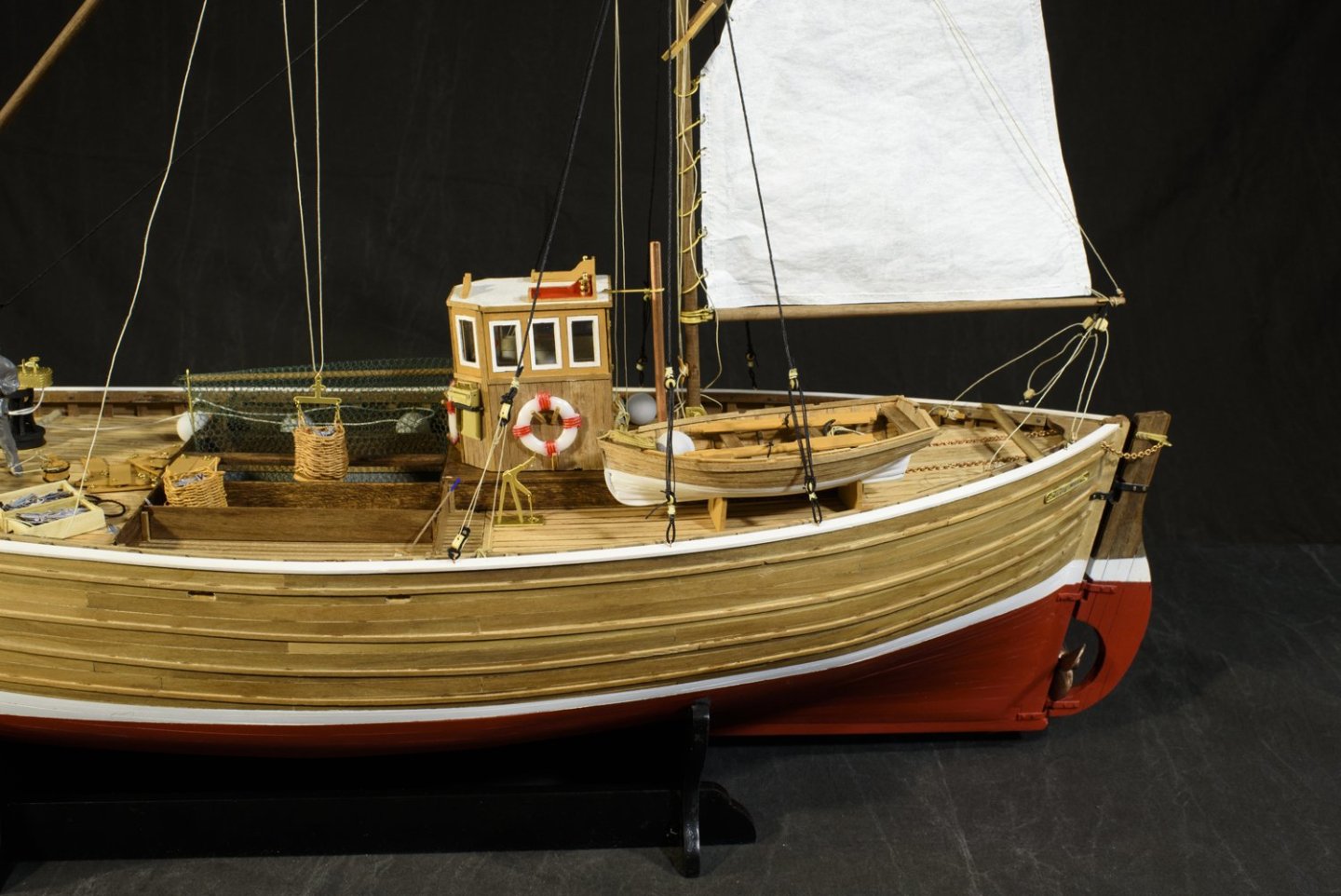
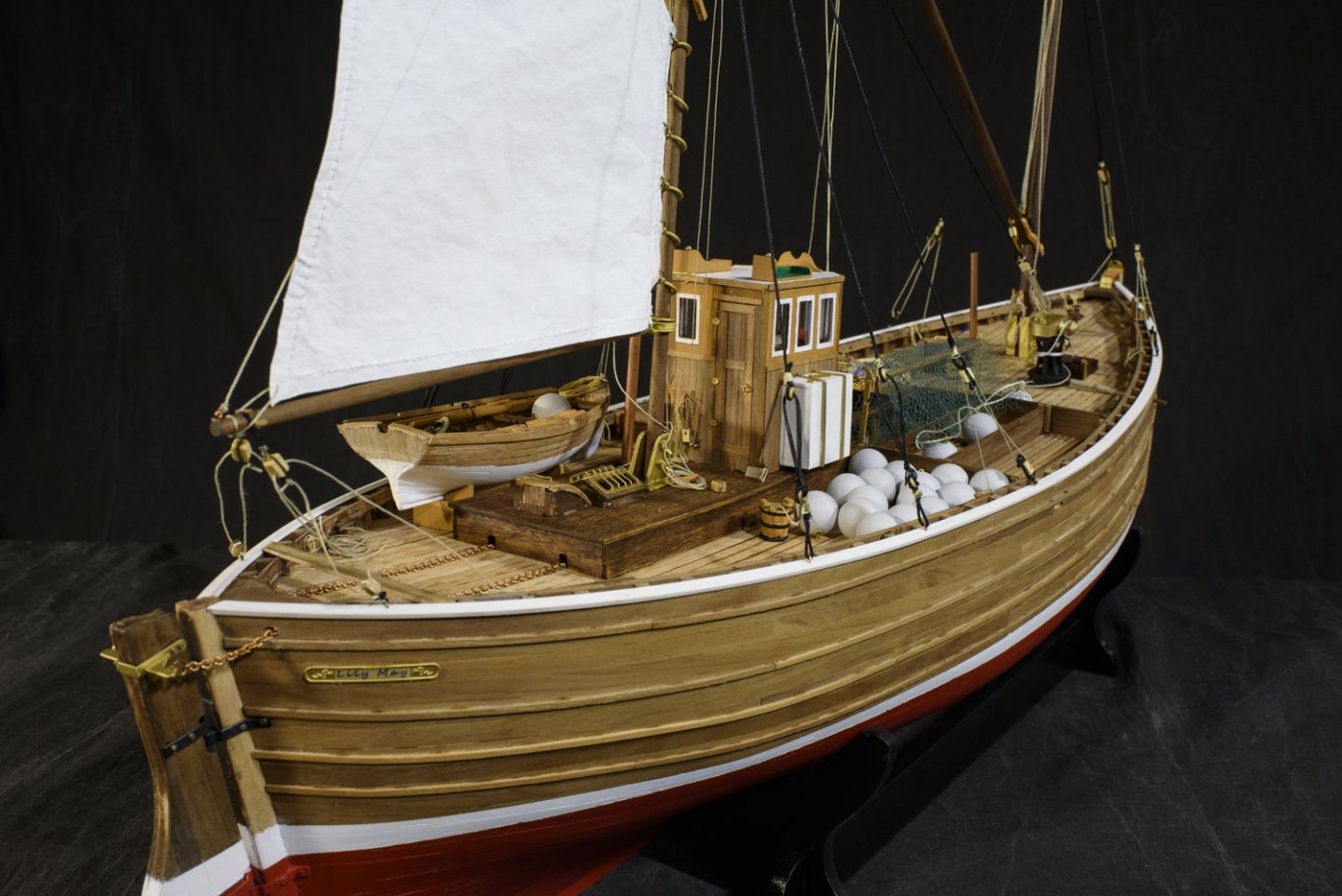
Thats it, I have completed the build, and I think the furled sail is the pose I will display this boat. I sure appreciate this forum for all the information it provides. And especially those people who built their Fifie's before me or are in work building theirs now. It is an inspiring community, and all are very talented. I get better with each kit I build - but looking at other builds I see even better skills. All the insight, tips and examples continue to inform me of how to be better. Also, thanks for all the comments as they are encouraging. God bless you all, and thanks again. - Ken
-
I have assembled the boat, as you can see in the following pictures. Next I will furl the sail and display it furled. Later this summer I will paint the captain and build a display case, neither of which I have done before. Thus the next post with furled a furled sail will conclude this build log. 🙂


-
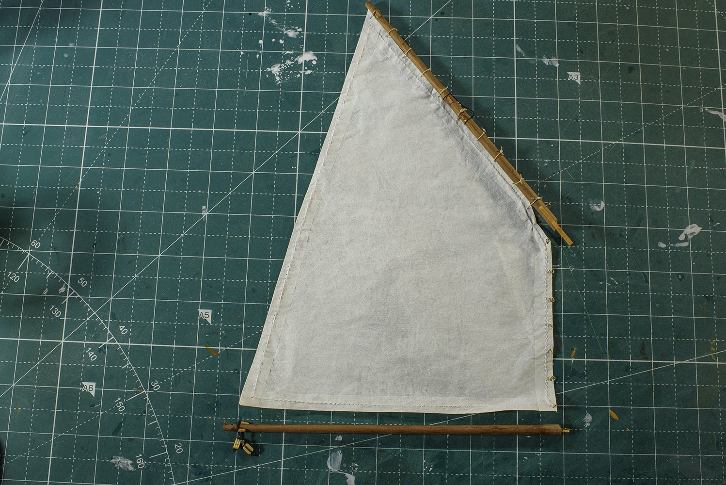
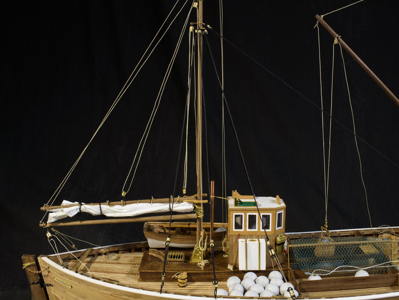
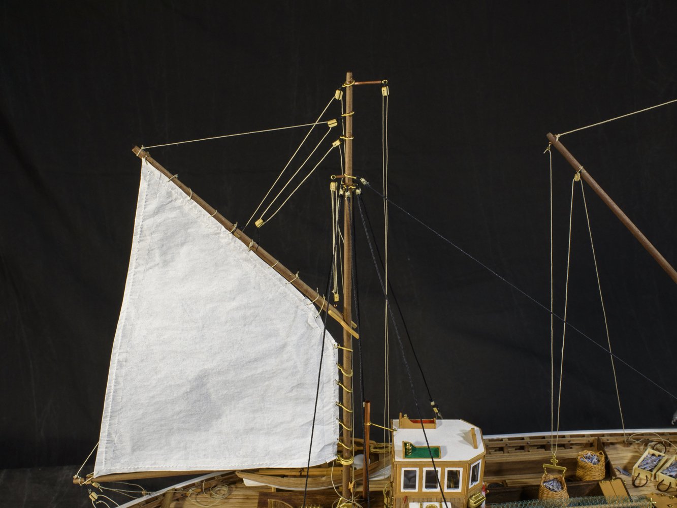
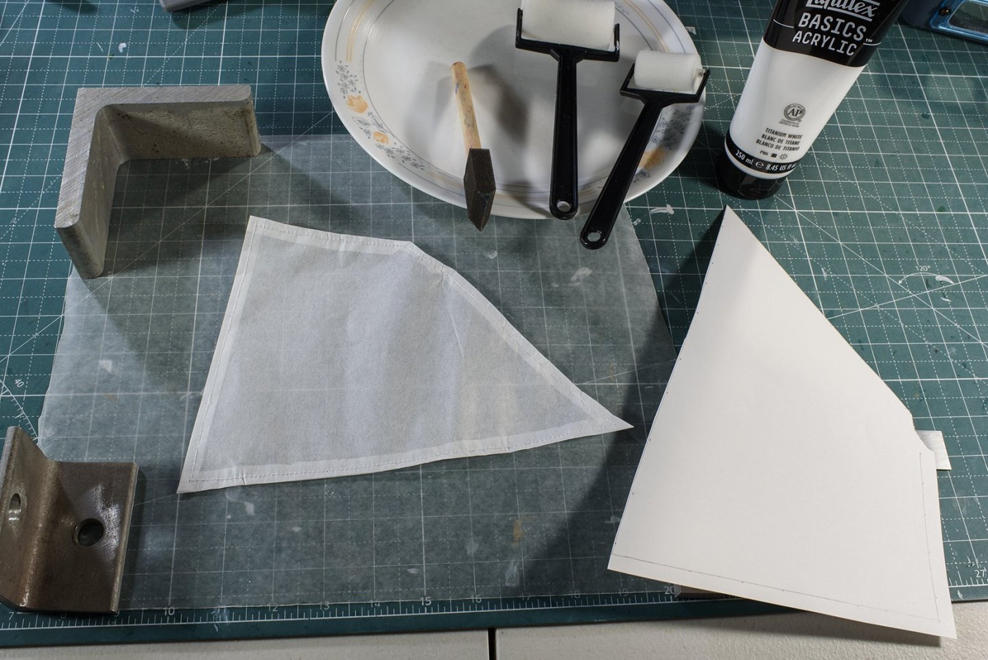
Next, I tackled the aft sail (as the fore mast will be rigged as a derrick). I liked what Tom Lauria said and showed on his YouTube channel, “Making Sails for Ship Models from Silkspan, Parts 1, 2”. I’ve been wanting to learn how to make more realistic sails. Since the cloth provided in our kit was a bit thick and coarse for me, I took the chance to learn more about sails. Tom stated that Silkspan is thinner than cloth and comes closest to real scale canvas and is equally suited for furled sails. All my model boats are display with all sails aloft. So, again, I am taking this opportunity to learn how to furl my model sails. Tom’s instructions are very clear, so I won’t repeat them here. I will say I have always had problems following instructions, and this is no exception. His video shows that he painted the silkspan before he cut the sail out. I cut the sail first, but the result turned out good anyway. He also showed using strips for the edge seams. But I had my wife sew the edges, as I am familiar with this “look” and it was easier for me (she did the work!) Below, on the right is a cardboard cutout derived from the drawings. To the left is my silkspan sail with the sides sewed. The upper part of the picture shows the Titanium acrylic and the foam application rollers he used in his video. Silkspan is a paper product which is sold under many names and was hard for me to find. But I found some on the internet from a model airplane kit manufacturer, Sig Manufacturing. I bought SILKSPAN TISSUE GM [MEDIUM] [Pk of 6 sheets]. Of course, after re-reading Tom’s YouTube description, I see he lists Bluejacket Shipcrafters as providing it as well. The next picture shows the painted sail with those miserable 3mm rings. Since the sail is paper, I am being very careful not to tear it. I am giving some thought on how to mate these smaller sail rings to the larger mast rings. This may be tricky! I plan to take some pictures with the sail hoisted, and then permanently furl the sail for display.

-
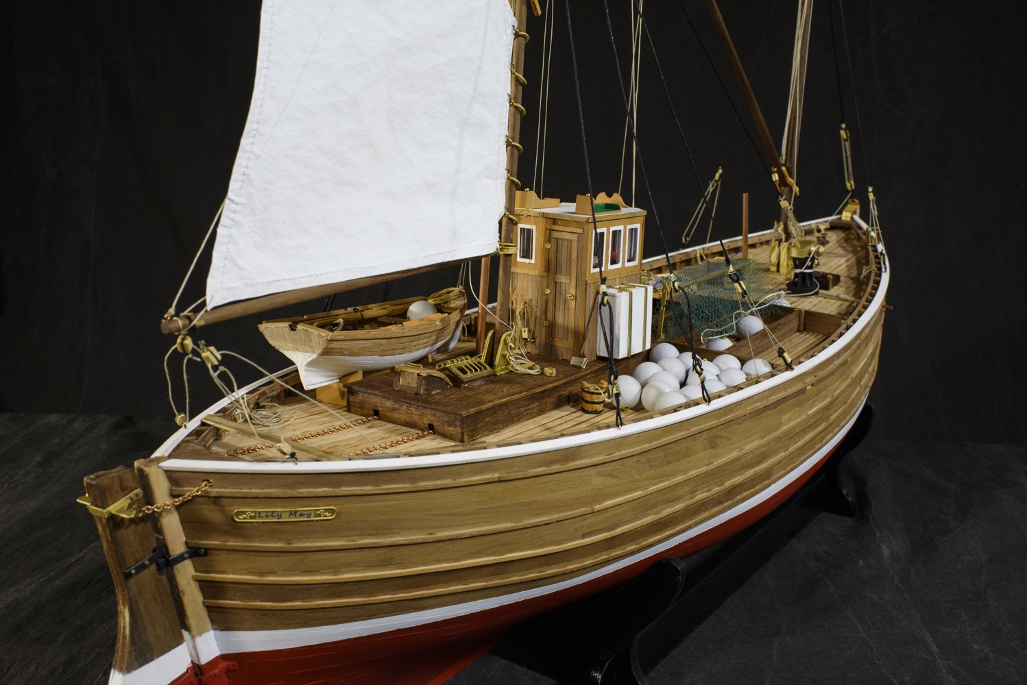
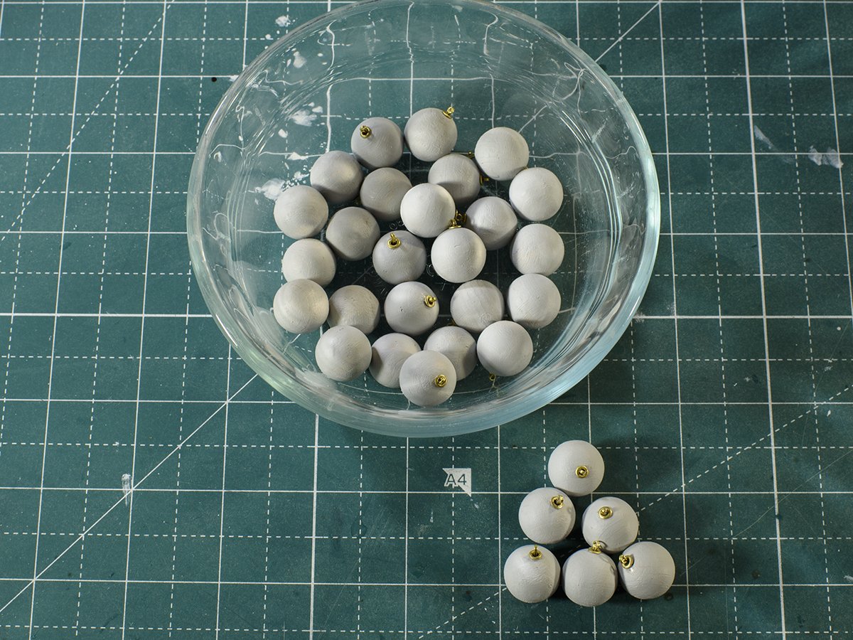
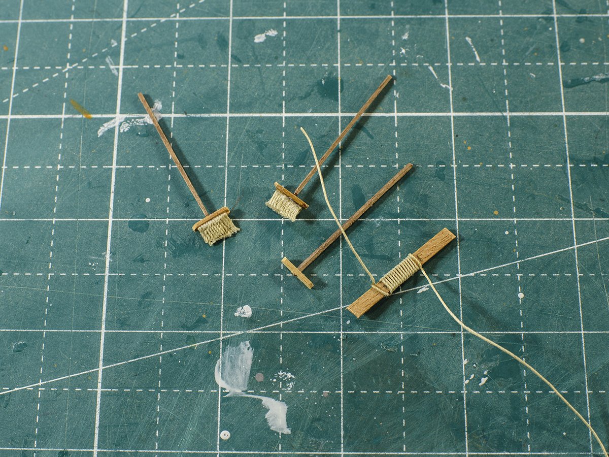
I am heading into the “home stretch”. I finished the 31 net floats, and I am working on the brooms. These were tricky, and it took me several tries to get some decent looking brooms. As you can see below, I have two brooms, and a third in work. But some of the broom bristles (thread) on the finished ones look funky. I will keep making more until I get 3 that are at least good on one side.
-
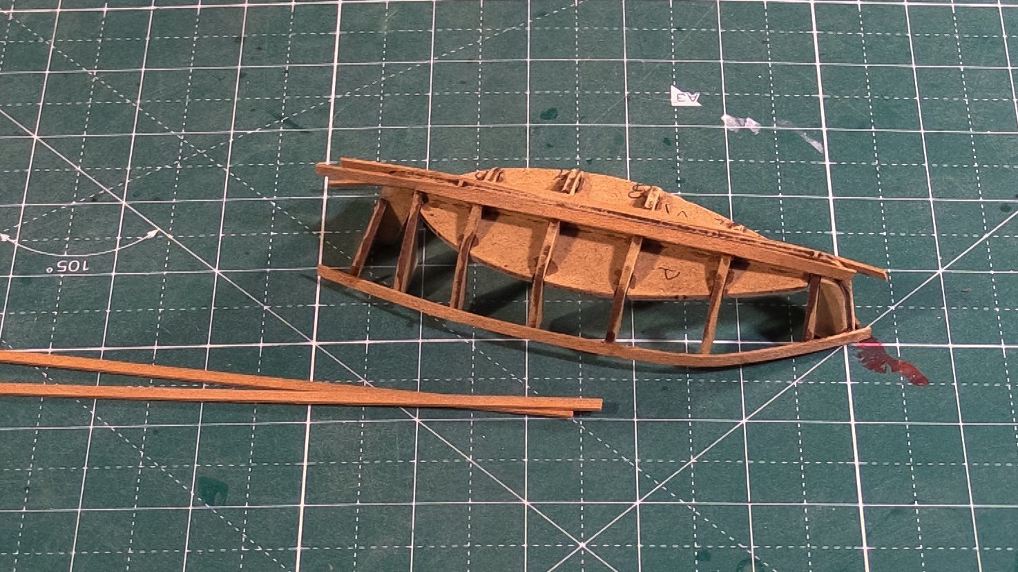
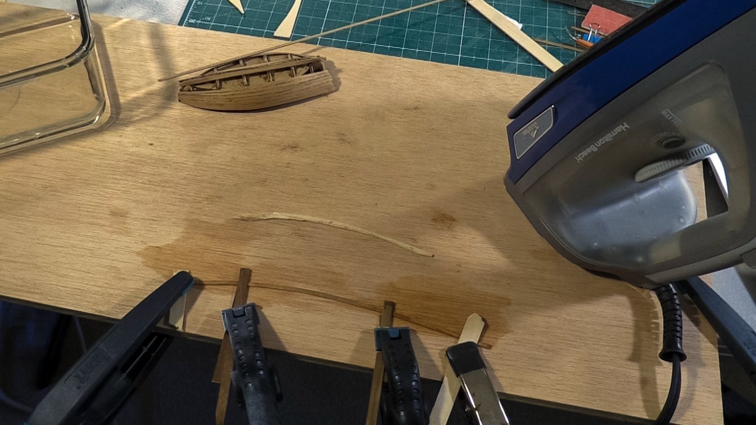
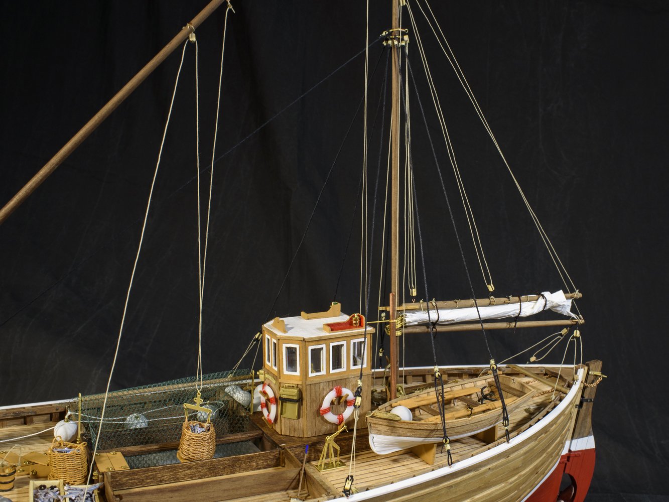
I turned my attention to the lifeboat. This took more time than the pilot house! – very time consuming. I assembled the frame, laid the garboard and wale planks, and proceeded to lay the planks in between. I narrowed the for and aft sections of these planks, but as I neared the bottom, the twist on the planks was significant, and required that I edge bend these. The lifeboat’s planking was not as smooth as I was hoping, even after sanding. Oh well.

-
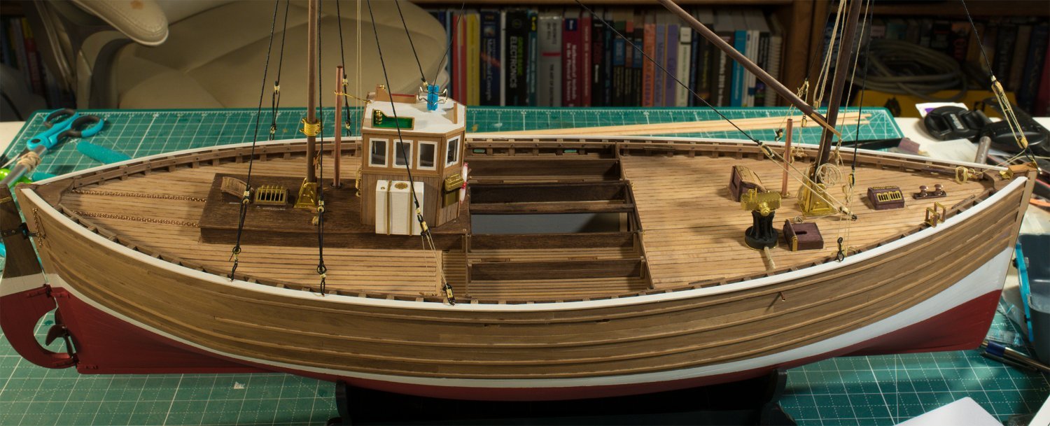
Next I installed most of the equipment on the deck, rigged most of the forward derrick mast and boom, along with most of the coiled lines.

-
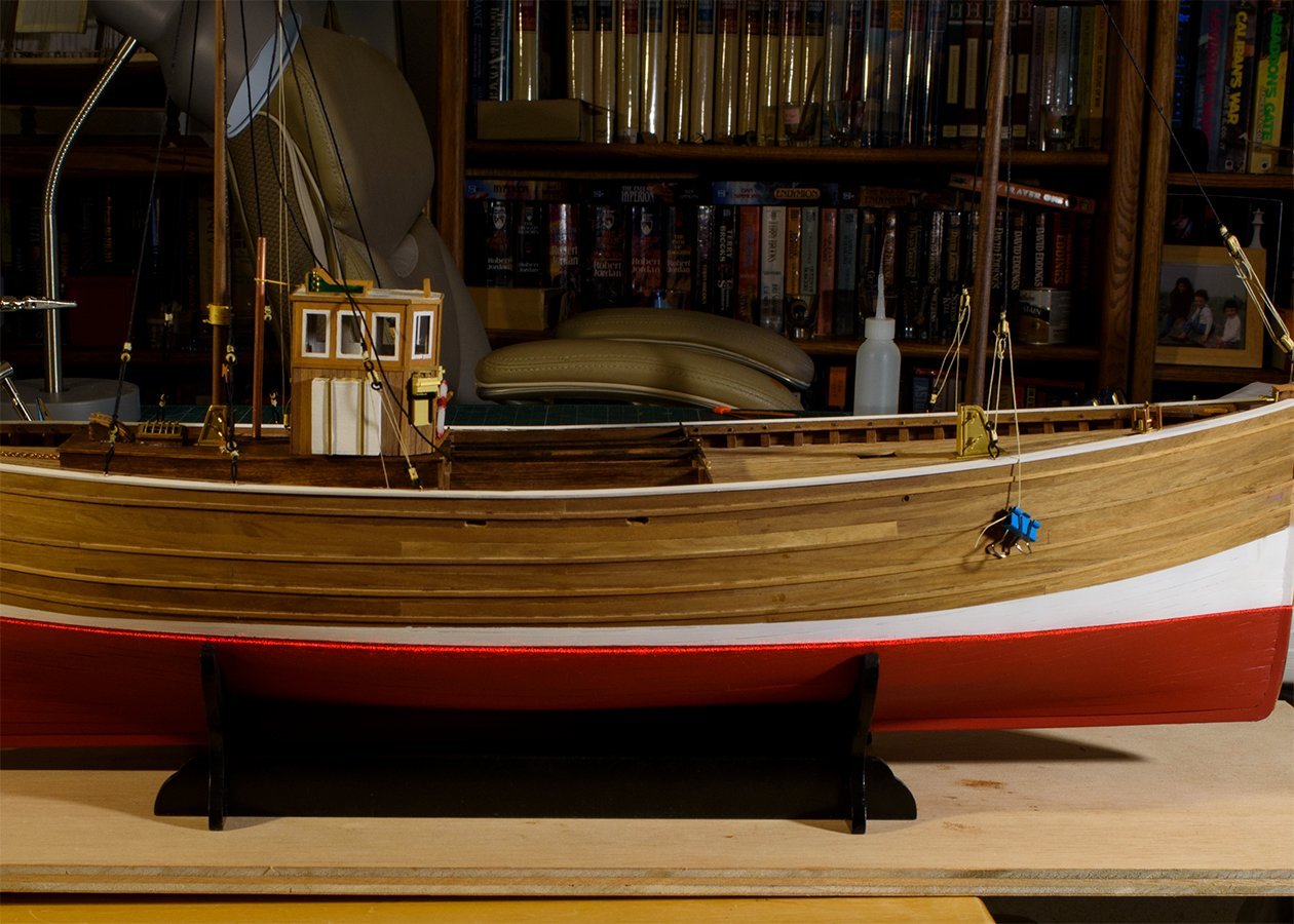
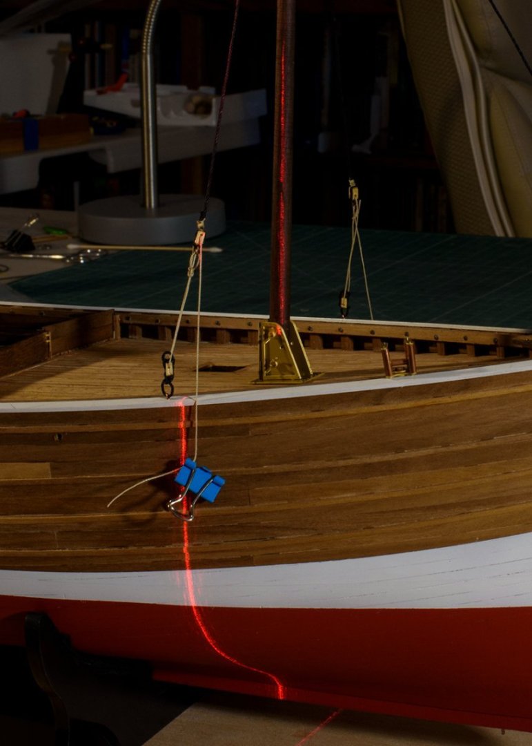
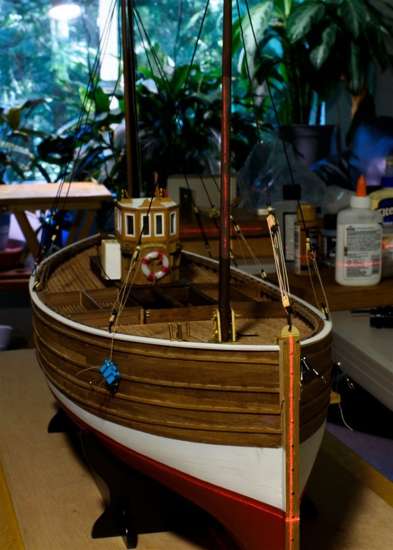
I used my Homedepot laser leveler to level a wooden platform, requiring two shims. Then, ensured that the cradle was level. I set the boat in the cradle with the stern 20 mm lower than the bow. The laser line confirmed the lower part of the boot-top to be level with the water line. I then used the pendicular laser feature of the laser level to set the masts straight fore and aft as well as “square” port and starboard. Once squared up, I glued the masts in place. They are slightly off from straight up, but close enough for me. A real boat would rely on the stays and shrouds to keep the masts straight and over time, the crew would adjust them as needed. However, since the thread used in the model will relax over time and will allow the masts to sag, I used glue to hold the masts in place, since there is no crew to make corrections! 🙂

-
Thanks David!
-
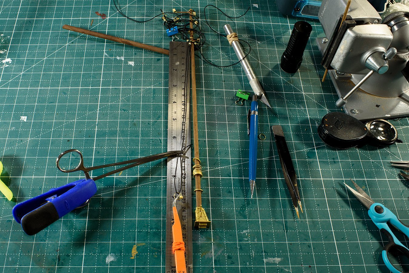
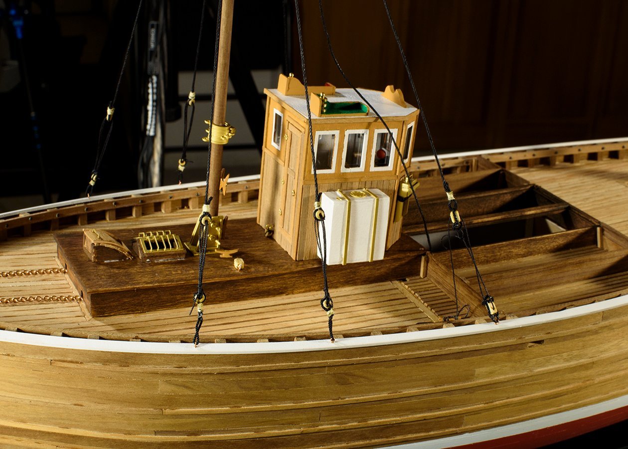
I used the kit drawings to determine each shroud length. I placed a ruler against the upper shroud ring, stretched the shroud, and made a loop where the thimble should be placed. Using forceps, my vice, and various clips, clamps, and coarse language, I installed the thimbles and blocks. I gave up on using wire to hold the thimbles in place, since the forceps and glue worked just fine. Once the shrouds were terminated with thimbles and blocks, I seized corresponding thimbles and blocks to eyelets. I used the drawings to locate where to drill and glue the eyelet assemblies. Then I wove the thimbles of the shrouds to the thimbles of the eyelets. Now that the mast and shrouds are installed, I started to place some of the aft deck equipment (the pilot house, various cleats, etc.). I noticed one of the shrouds was too long, so I undid the one lower shroud thimble, and shortened it and reseized it so that all of the thimbles would be of similar length. Now I see that the forward shroud blocks are connected with black line rather than the tan line. I guess black line represents standing rigging, whereas these blocks must be used to adjust the mast rake and are thus running rigging (tan). I’ll change the line to tan. I’ll install more of the aft running rigging and the smokestack, and turn my attention to the foremast. I plan to rig it to support a derrick boom. From there I will install some of the forward deck equipment. There is still a lot to do! I agree with David (above). I had hoped to be completed in 12 months. It is near the end of February (14 months), and I have not yet started on the small boat nor even decided on my display configuration. Now I am hoping to be completed by June! I did log my time during planking, and it took me 280 hours to finish the 2nd layer of planks. Clearly, I am slow, but clearly, Amati's estimate of 100-150 hours for total build was optimistic. Good insight David - Amati's estimate is off.
-
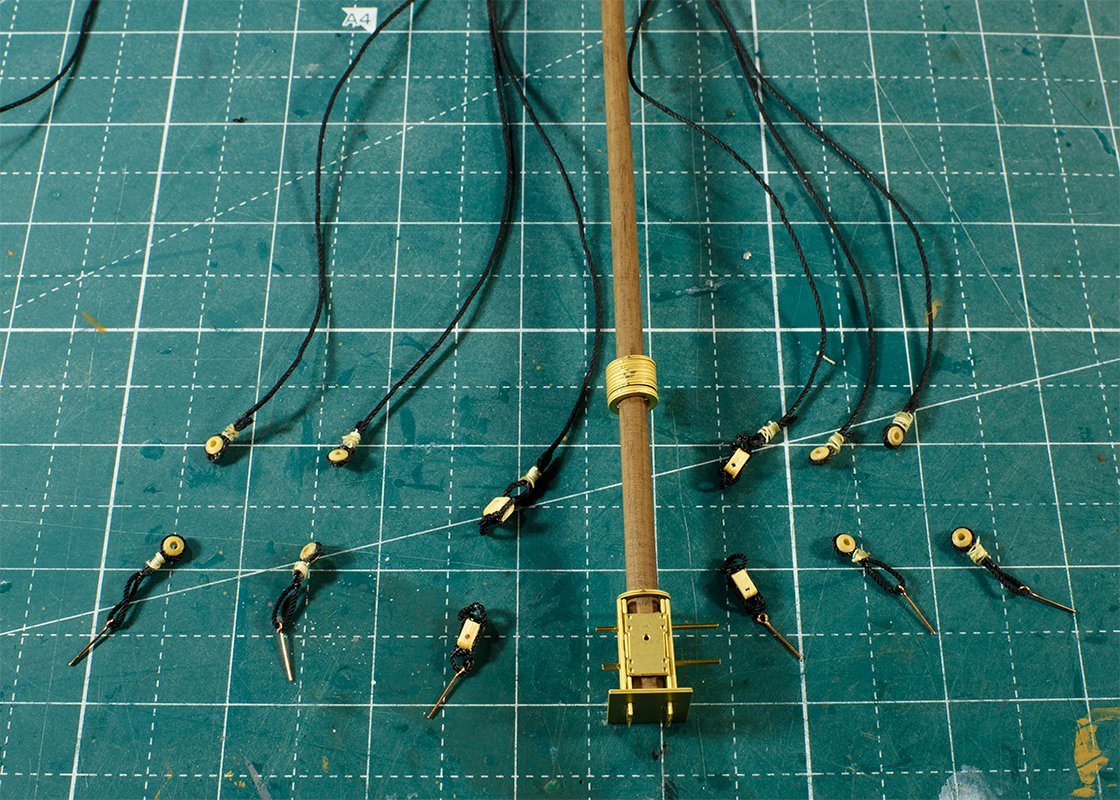
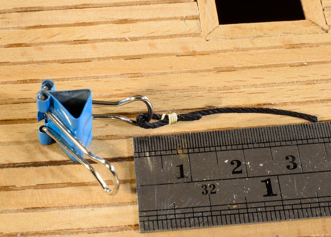
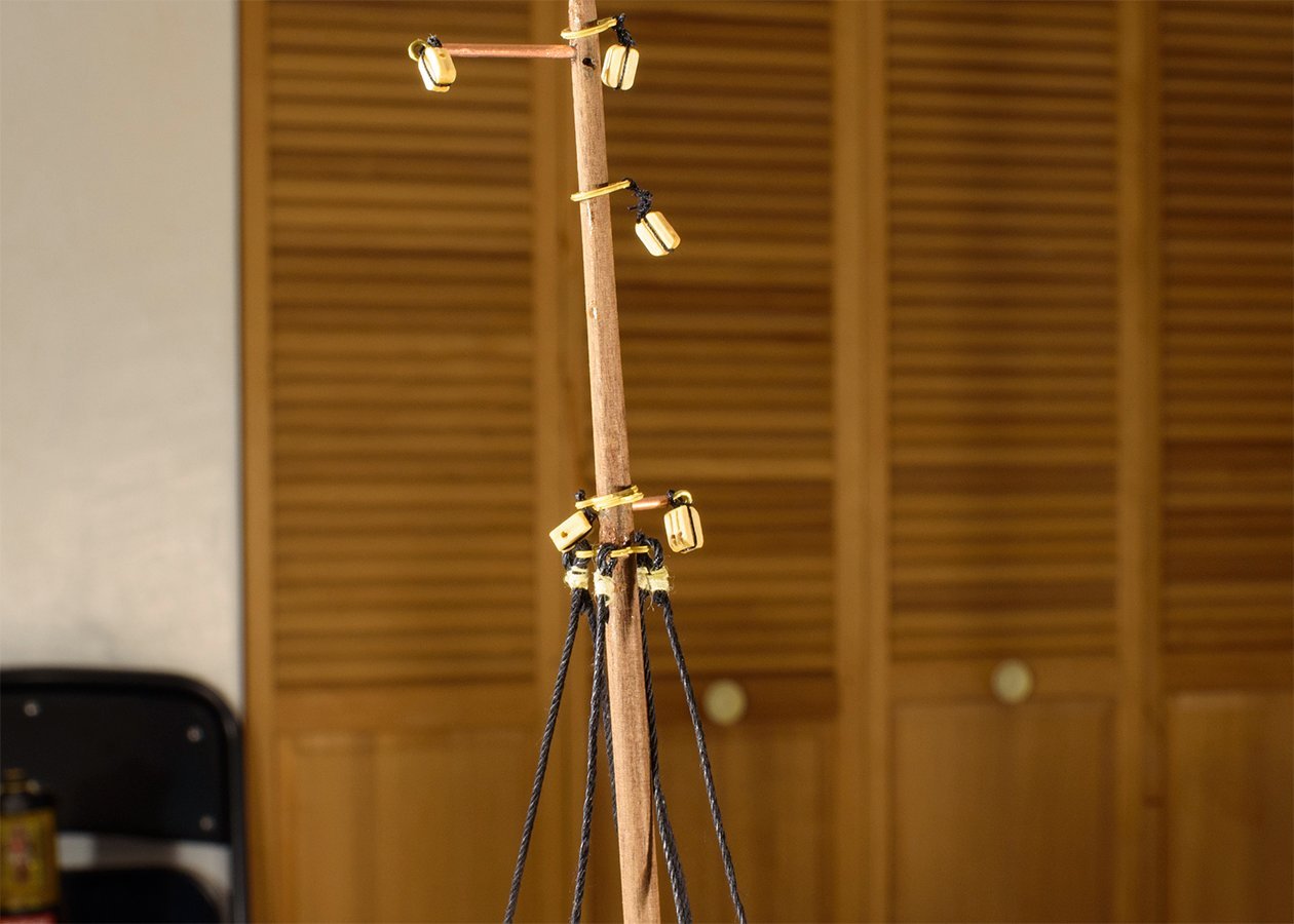
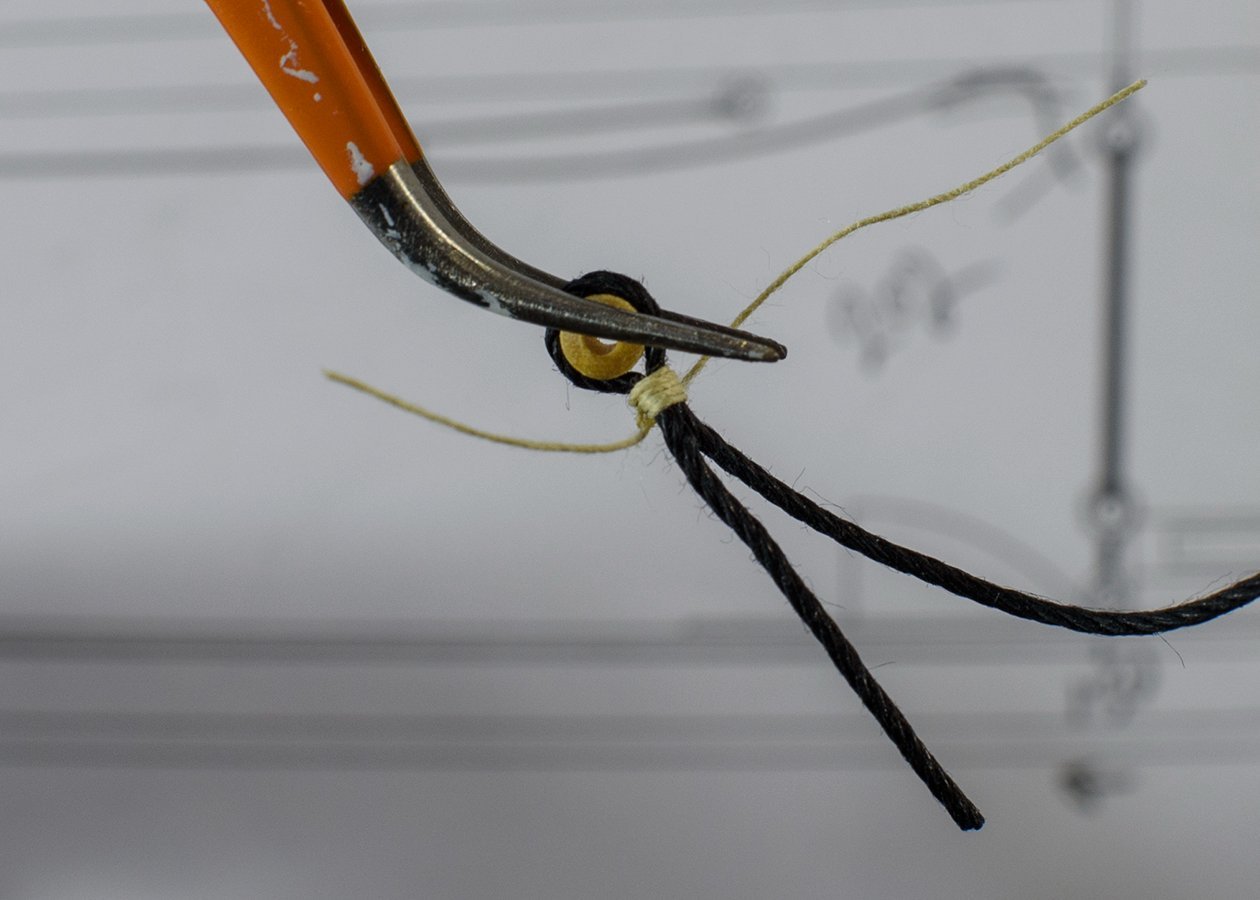
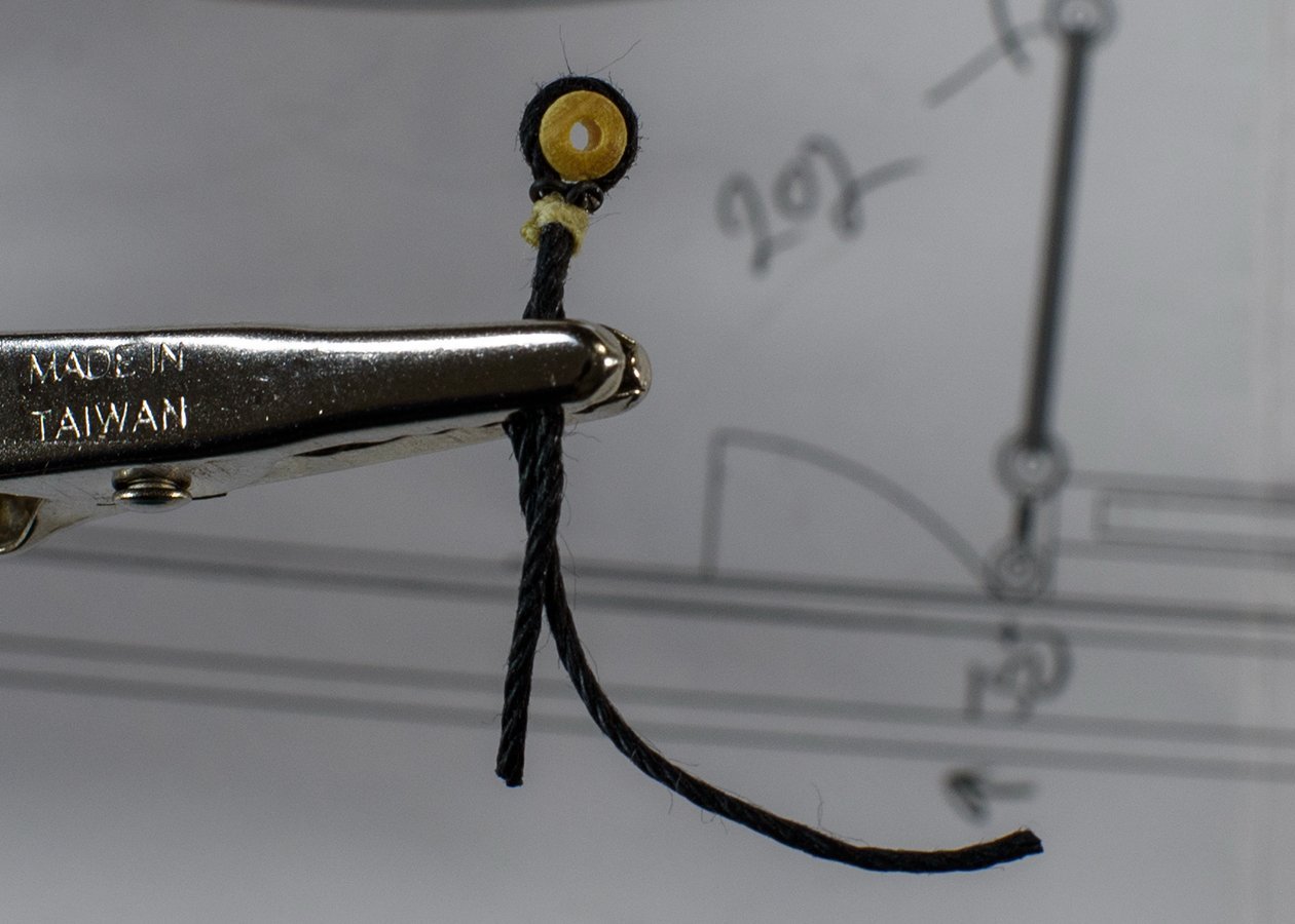
I decided to install the two masts onto the boat before I add other equipment. These masts seemed wobbly when seated in the deck and superstructure. It seemed to me that I need to add the shrouds and stays to get the mast angles correct and secure before I proceed. I had previously added the blocks and rings to all the spars. The next step was to add the 6 ends of the shrouds to the mizzen spreader band (157). The drawings showed the lines being seizing to these 6 loops, so I practiced my seizing (see below). Once I reviewed seizing, I chose some 0.3 mm thread from another boat and seized the 6 shroud ends to the mast. Next, I decided to use the dimensions from drawing 7 to locate where to seize the wooden thimbles (202) to the lower end of the shrouds. I hope the thimbles end up somewhat even with the deck and one another. I will do a dimension check before I permanently fasten the thimbles and cut and seize the shrouds. Again, I practiced seizing rings. First, I used just the seizing thread, but as hard as I could work, I could not get the thread to provide a solid grip around the thimble. It seemed like an awkward push would knock the thimble out. Also, after time, the line will relax, become looser, and again the ring could be knocked out and worse disappear, being so small. (There were no spare rings provided). I thought about gluing the line to the thimble, but I ended up adding 0.4 mm black wire. Next will be the stays, and this should create a firm and stable aft mast, mounted to the Super structure. After this (a week or more) will have to study what comes next. Any suggestion about better assembly methods or the future sequence of events will be appreciated. Comments or suggestions are appreciated, even if I have finished the task - I try to use lessons learned on future boats.
-
I’m not sure of the next steps of the assembly sequence, but I will focus on assembling the superstructure onto the boat. The rudder chains needed installation first. Then I added the “fish pen” and then the roller assembly for the nets. The roller assembly is fragile, so I will remove it from the boat until the boat is completed, where I will determine the display configuration, and likely put them in then.