HOLIDAY DONATION DRIVE - SUPPORT MSW - DO YOUR PART TO KEEP THIS GREAT FORUM GOING! (Only 53 donations so far out of 49,000 members - C'mon guys!)
×


Ken_2
-
Posts
150 -
Joined
-
Last visited
Content Type
Profiles
Forums
Gallery
Events
Everything posted by Ken_2
-
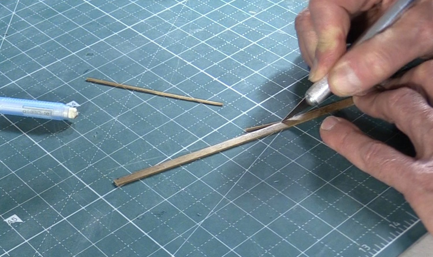
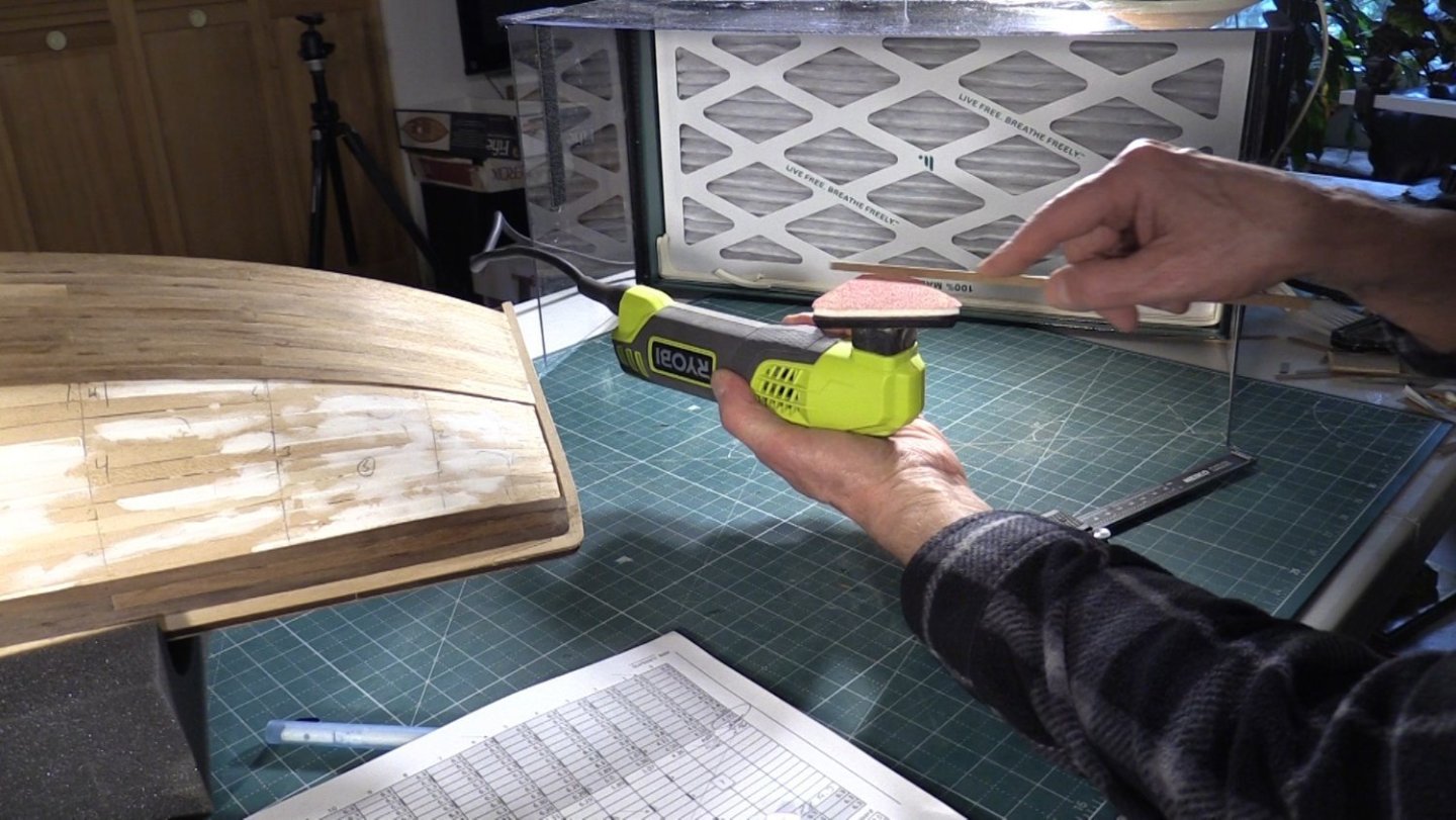
My goal was to keep the top layer of walnut planks as close to each other as possible. I have achieved much better results than previous builds. I took my time, figured out things I was doing wrong, and corrected my planking process. There were close to 300 planks that make up the 106 strakes for both layers, so there was plenty of time to practice. I can summarize my improved planking process as a 3-stage trimming process. The 1st stage is a rough trim. I used my digital calipers and I marked each plank with the desired widths and drew a line close to the desired width of the plank. Using my Exacto blade, I cut away parts of the plank that required significant sanding. The 2nd stage of trimming utilized a small orbital sander which was used like a planer to sand away the remaining parts of the plank, measuring 4 or 5 positions between frames and being very careful to not sand past the desired width (sanding too much results in a dreaded gap). Thus, there was a lot of “sand – measure - repeat”. The 3rd stage consisted of spot hand sanding. Once the plank was sized, it was put in the final position. Then 2 things could be determined. First, I looked for gaps caused by high spots. These were hand sanded out. Gaps caused by low spots (too much sanding) often resulted in a redo (start over). Second, I looked to see if an “edge bend” of the plank was needed to fit the curvature of the hull. All of this resulted in a much tighter fit. Once all of this was completed, I put a small bevel on the back top of the plank to help it fit better with the abutting plank.

-
A gorgeous model. Makes me want to go fishing on one! Ken
-
I love your detail work! You set the bar very high. Keep it up! Ken
-
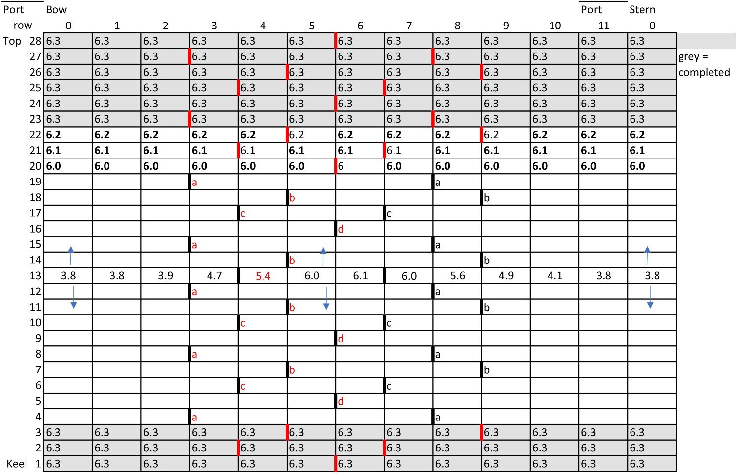
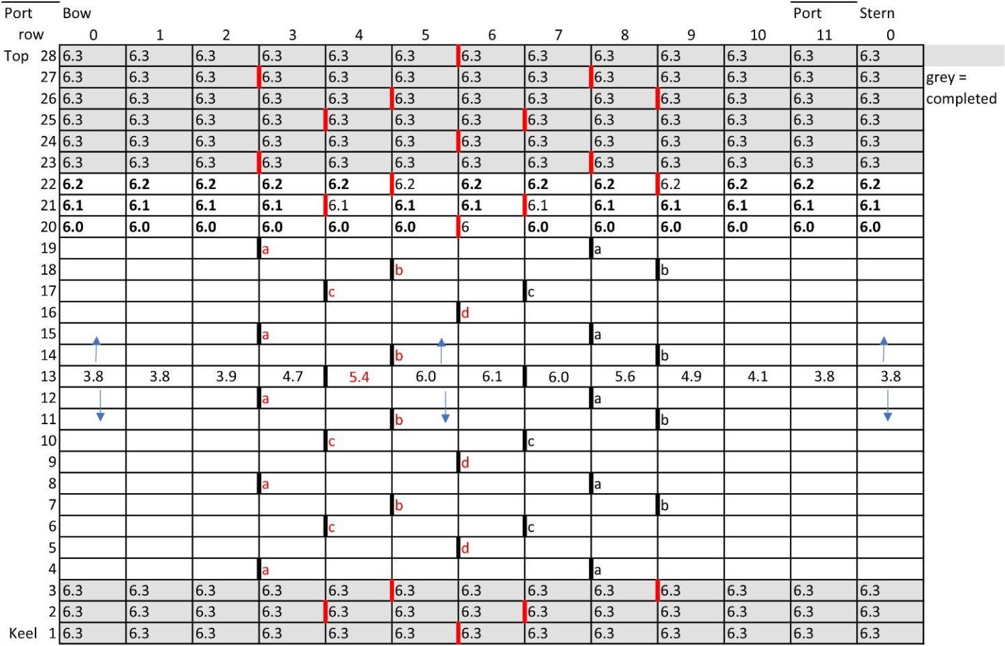
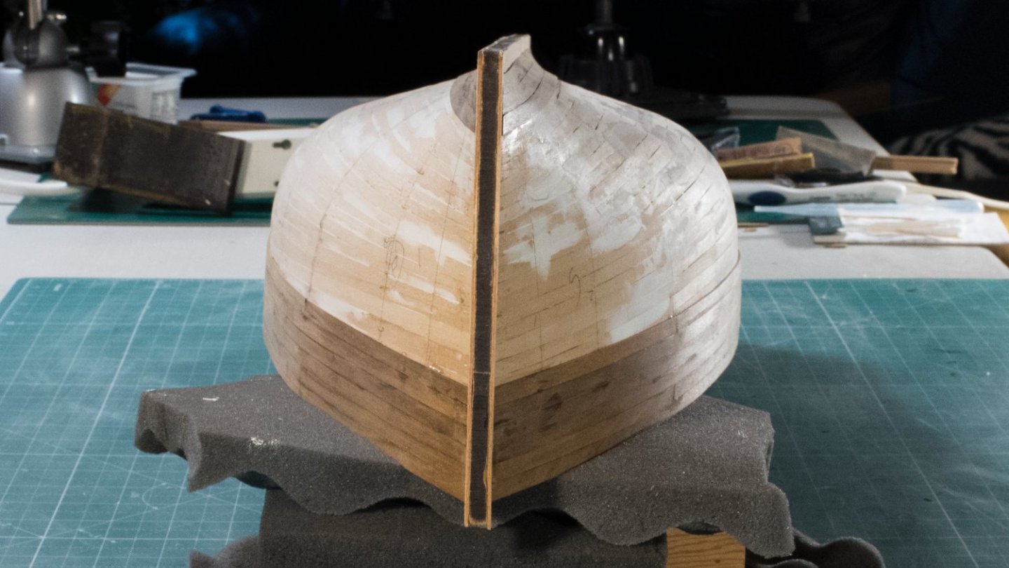
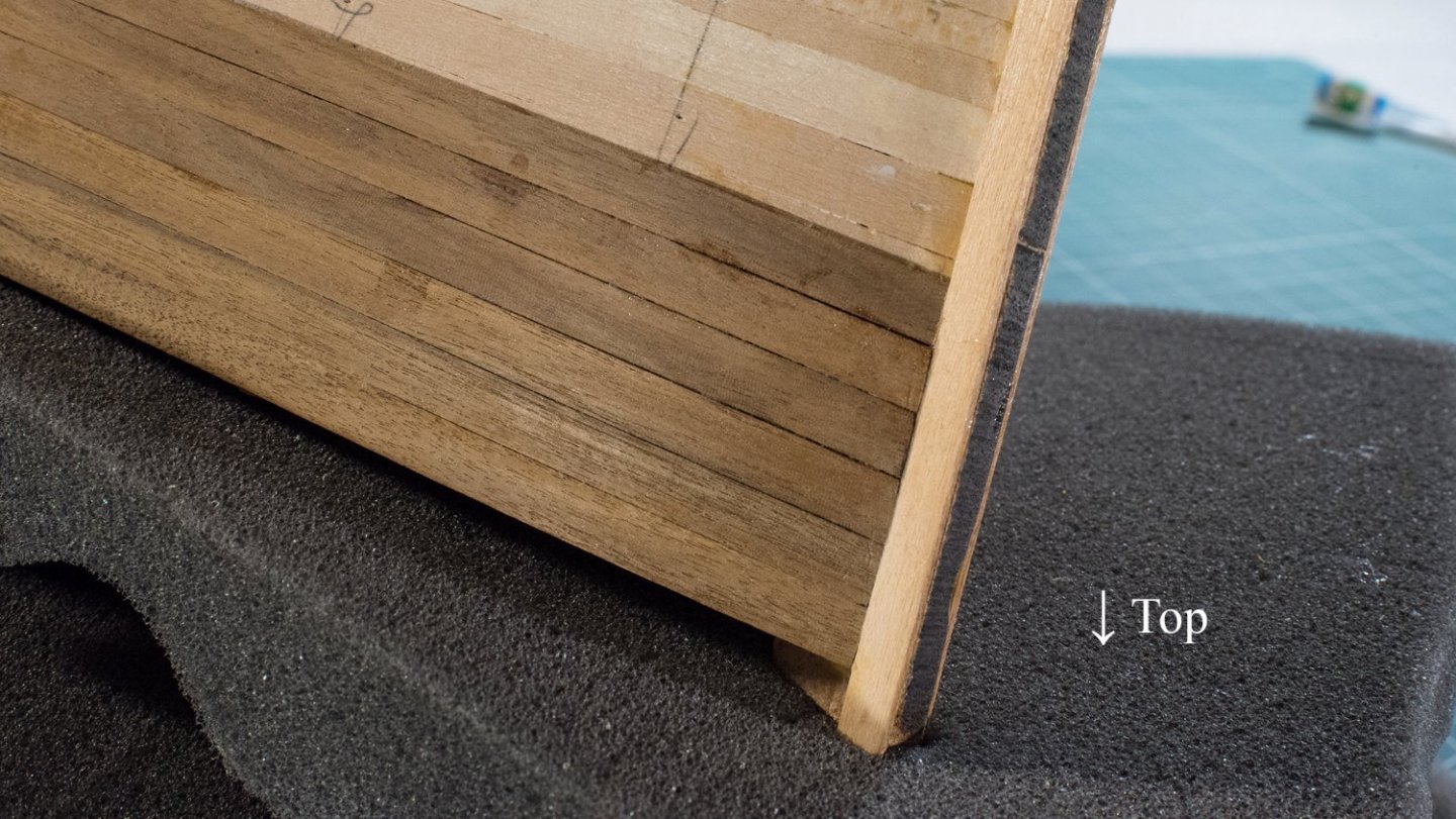
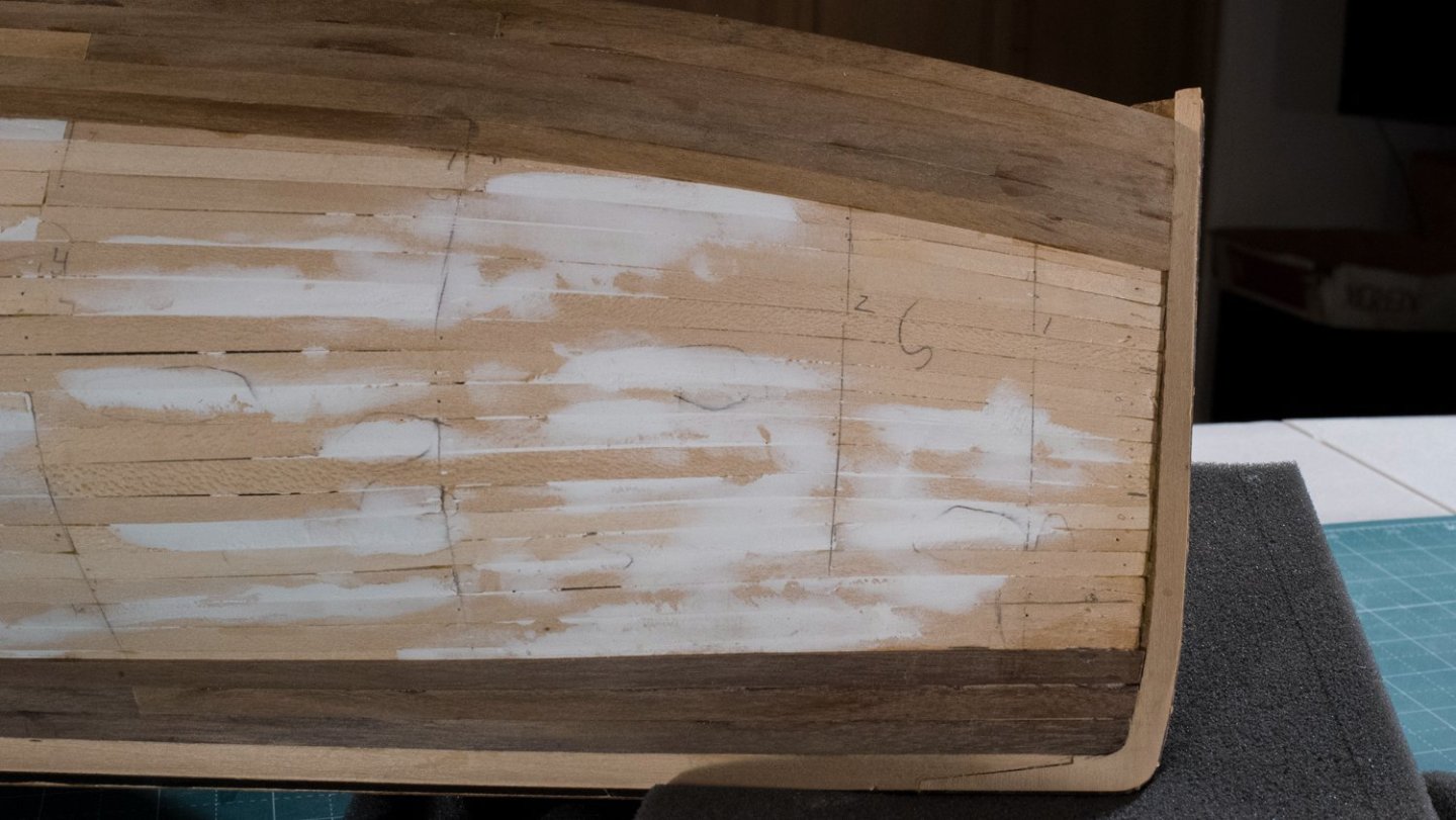
Thanks to Dsmith, I spent some additional time sanding and filling the first layer of planks. I am sure the 2nd layer of planks looks better because of this extra care. I am using Excel to plan my plank width along with the 4-rowshift pattern for the butt joints. As a reminder, I would like to have my planks run fore and aft with no drop planks nor pointy ended planks. Since the distance along the frames from the top to the keel is greatest at the beam and least at the bow, the ends will need to be narrowed to maintain planks that run fore and aft. The Excel picture shows I use 6.3 mm for my plank width. I measured the distance consumed by 4 rows of installed planks and divided by 4 to get 6.3 mm. This includes any gaps, Glue, and curvature. The individual planks vary between 6.2 and 6.25 mm. I plan to paint the boat just like the box, with the top rows of planks to be natural wood, followed by a white strip, followed by a red bottom paint. Thus, I selected the lightest colors of mahogany from among my pile for the first rows. I have tried to figure out where the white strip will be relative to planks, but this location seems illusive to me. My boat is several mm shorter than the 1:1 drawing depicts. I will remeasure again, and I can deal with this variation, but the location of the white paint allows me to loosen up my tolerance for gaps and compensate with a little filler (less rework for me). In addition, the paint is where I will start to transition to the narrower planks. I played with the excel file to see how many full-size planks I can put on top, before the follow-on planks in the middle become too narrow and are so narrow, they look funny. Another option is to use drop planks, but that is not my plan. My current plan allows the top 9 planks to be wide, and the “middle planks” to be 3.8 mm at the bow and stern. I am hoping 3.8 mm is not too narrow (3.8 mm = 60% of 6.2) so it should be fine. I remeasure the remaining space to be planked every few planks to replan my widths. To explain the file: The grey cells are the planks currently installed, (rows 28-23 and rows 1-3). My next task is to install custom sized planks (rows 22-4) shown as white on the excel. Rows 22,21, and 20 are uniformly narrowed by 1 mm each, hopefully making the transition to the more narrow planks less obvious. The remaining white cells are to be narrowed - differently at each frame, using the widths shown in row 13. Any gaps from my imperfect sanding for these truly customized planks will be painted. Paint will hide a little filler, and planks many will be on the underside of the hull, which is less visible. Thus, after my next 3 rows, I will need to know exactly where the paint starts!. As for the currently installed planks, I used Titebond II wood glue for a few planks, but for the first time, I am using medium thick CA glue (which dries slower) and I’ve had some good success. I’ve had to remove a few sections of planks due to gaps etc. but overall, it is much easier than pins, nails, paperclips etc. I’m impressed. The pictures below show signs of this glue since I have not done much sanding. After completing the planking, I will do a thorough sanding job before painting.
-
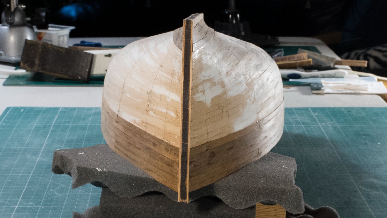
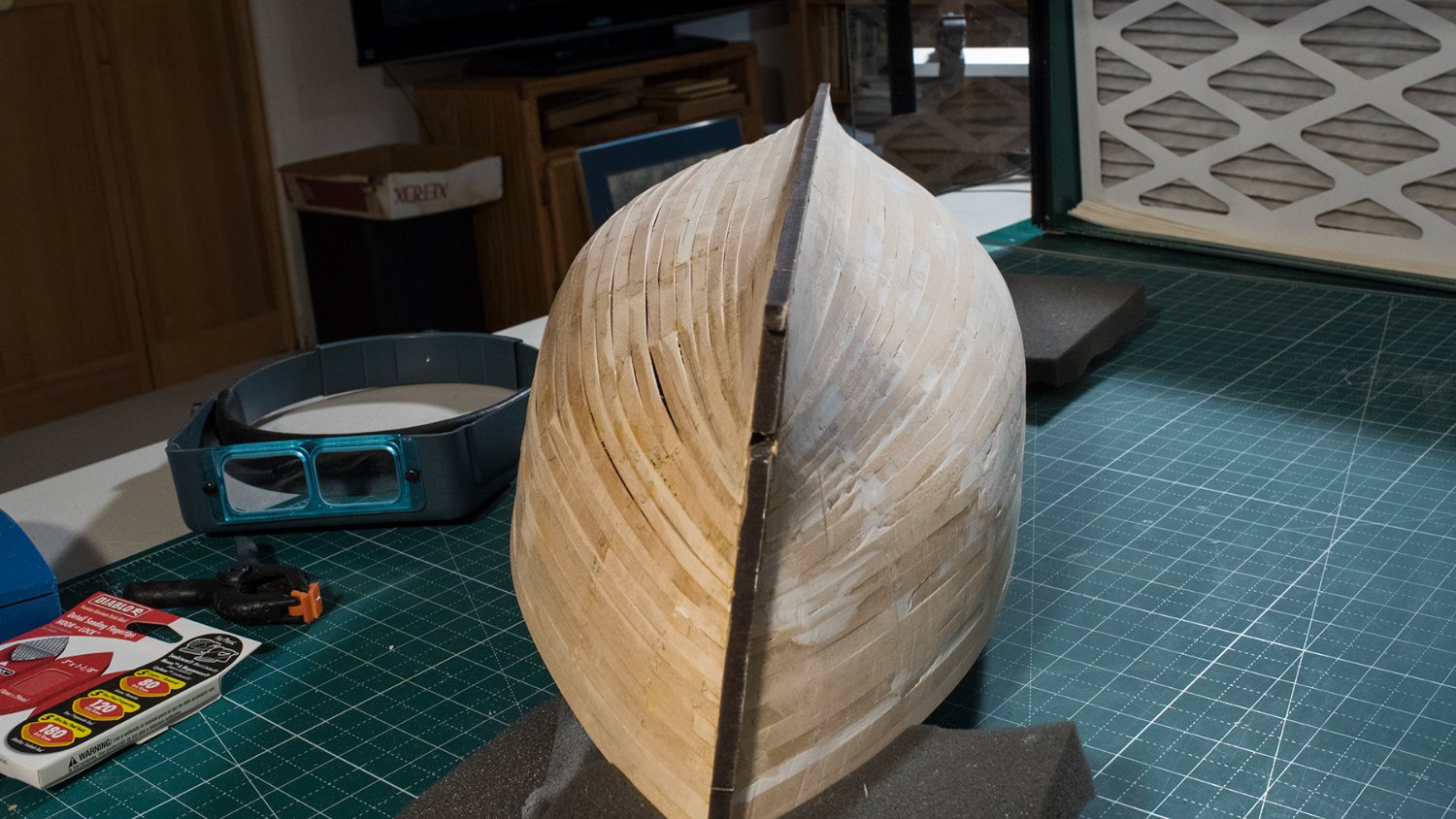
I have finished my first planking layer. I started by using planks that scale up on a real boat to be 15’ to ~30’, along with a 4 shift butt scheme, and carefully fitting them together with minimal gaps. After about 10 planks on top, and 4 planks on the bottom, it became clear this was going to take too long, especially since this first layer will not show. So, I finished using as long a plank that would edge bend gracefully, and an assorted set of shorter planks where needed. This still took a long time, but it was a shorter effort. It seems like my hope of filling and sanding will result in a smooth enough surface for the 2nd layer. As you can see below, I am not quite finished smoothing the Port side, and have not started sanding the Starboard side. I will finish both sides, and then start the 2nd layer, using planks that scale up to 15’ to ~30’ as well as using a 4 shift butt scheme, and carefully fit them together, hopefully with minimal gaps. ? What I am not sure about is how smooth the first layer should be. I will sand the obvious remaining large discontinuities. But many areas may be ready. They are smooth fore and aft, but I can feel an occasional slight ripple as I drag my fingers from the keel to the bulkhead. I laid a couple of the walnut planks on these areas, and it looks like they will cover/hide any slight irregularities. Does anyone have experience with what is "smooth enough", and what will make the 2nd layer look bad?

-
You hull looks good. I like your idea of full planks from the bulwarks down 10 planks, and 3 up from the keel, then tapering the remaining planks fore and aft. I plan to do something (if not exactly) like that. I use excel to determine the tapering dimensions. Any lessons learned on using CA glue for the final layer? Ken
-
That’s a good question, Don. I’d not thought that far ahead! So, I mocked it up, and thankfully it seems to fit. Since the top of the underlaying planks are near the top of the real keel, there is an edge where the false keel sticks up above the 1st layer of planks. This edge seems like it will mate well with the top layer. There is variation in fit, where the bottom layer planks meet the false keel, so I will try to manage that fit in future plank installment. And sandpaper or filing should provide a good finial fit! Whew! I’m glad I looked – Thanks – Ken
-
The planking is going OK. I must install more short planks rather than fewer long planks, but these shorter planks are easier to shape (i.e. bend, narrow and fit with the adjacent plank). It is good practice for me, since this is how full-sized wooden boats are built and I think this practice will make my future models look better (especially those kits which only have one layer of planking). I have never tried this before, and I am finding all kinds of little things I never thought of, so there are some gaps and re-work that do not look the best. Good thing this is an underlayment. I chose a 4-row shift pattern for the planking, as discussed in the instruction manual for the NRG Half Hull planking kit, found in the NRG Store. It took a while to figure out the spacing scheme (e.g. Butts on adjacent rows must be at least 5 feet apart, and others rules to prevent weak spots in a real hull). Finishing this first set of planks will be a task! I have 4 rows on each side complete – only 21 more underlayment rows to go, then the final layer (jeepers). I think it will be a while before I post again (or I go crazy) :-).
-
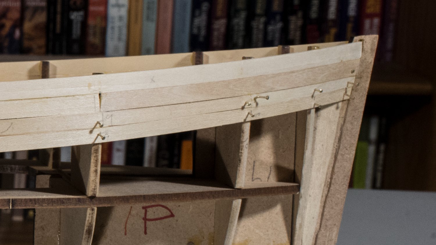
With the decks and spacers installed, I used a short plank along each of the surfaces to check the fit. The kit provided extremely long planks and the manual shows how to use them. The scale of these long planks is not realistic (63 ft long when scaled up 1:32) but they are OK to use since these are the underlayment for the top planking, and these longer planks will not show. I have elected to make my first layer of planks like the typical length of wood found in the day. I cut these longer planks shorter so that they would scale up to 2 x 10’s between 14’ to 29’ long, depending on the kit frame spacing. It also seemed simple enough to narrow these planks fore and aft so there should be no need for stealers drop planks or pointy planks. I also decided to carve a rabbet on the stem and keel to make the planks transition smoothly as they end at the keel. Another dry fit of planks after the rabbet was cut required another round of fairing of the frames and spacers. I am also finding I need a third fairing of the spacers as I install each plank.


-
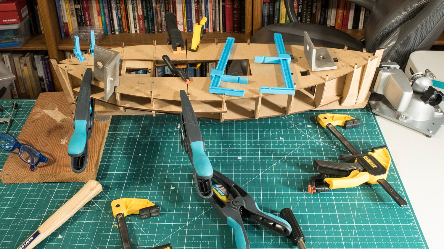
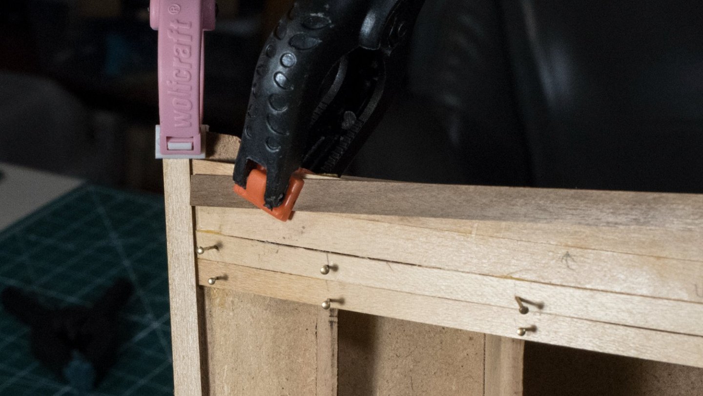
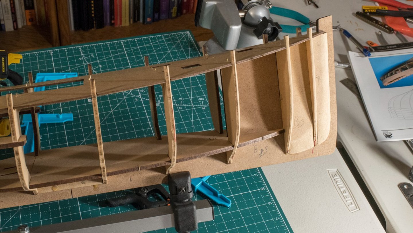
I glued all the frames onto the keel, and then dry fit the decks to keep the frames aligned while the deck glue dried. While waiting, I started shaping the spacers. I sanded them and dry fit them until they looked like they would align with the future planks and glued all the spacers on. I then glued the lower decks, and dry fit the upper deck while they dried. Installation of the upper deck caused me some trouble. It must be pushed down to mate with the sheer line of the frames. The MDF decking was stiffer than I am used to and required more strong and larger clamps than I have, to hold the deck down while the glue dried. So, I nailed the upper deck to the frames and beams (many nails missing the beams below). The nail pusher required a lot of force due to the thickness of the MDF, so I had to move the boat from my keel clamper and on to the desk for support.

-
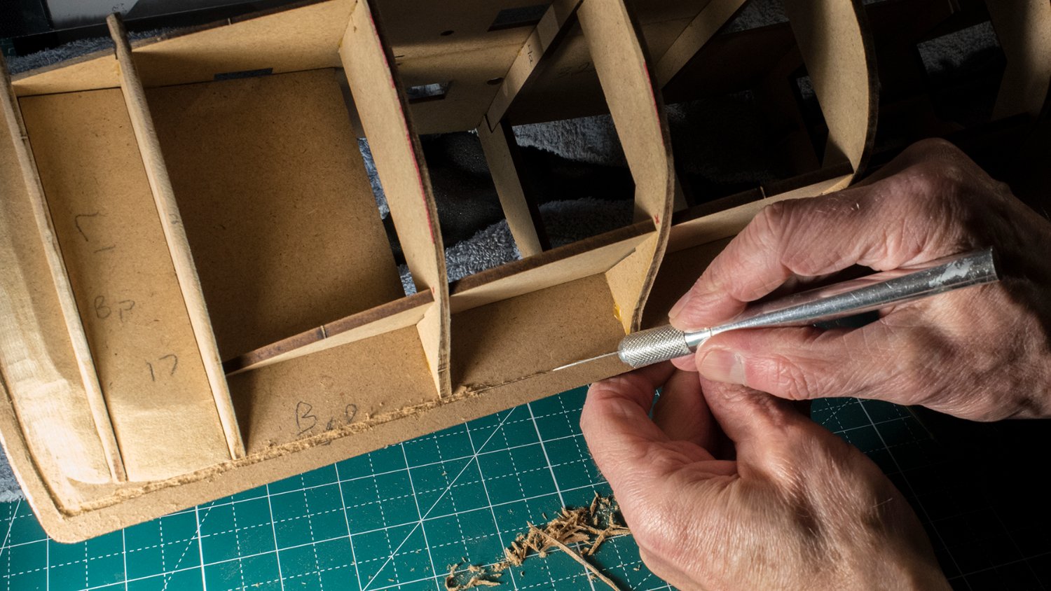
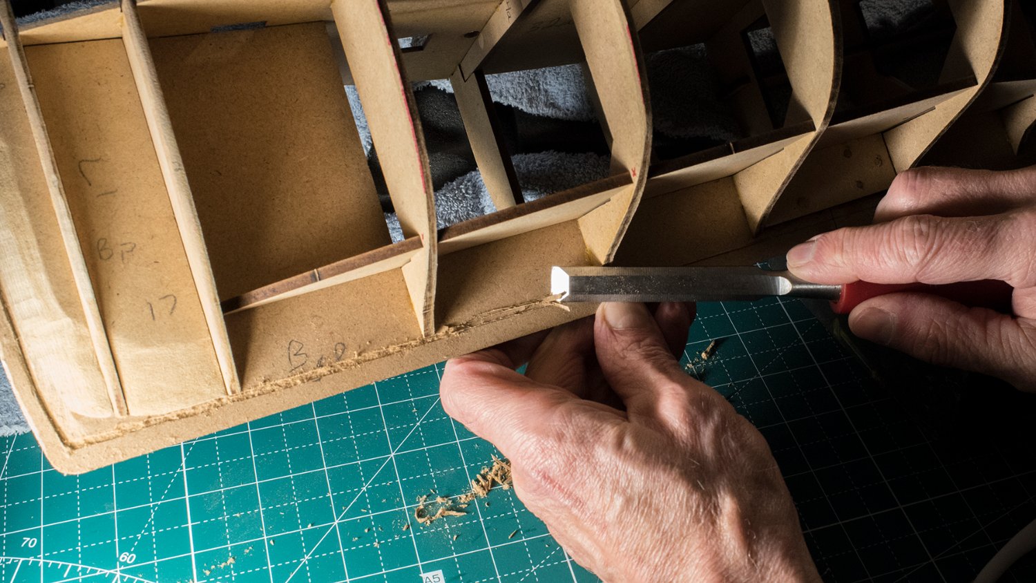
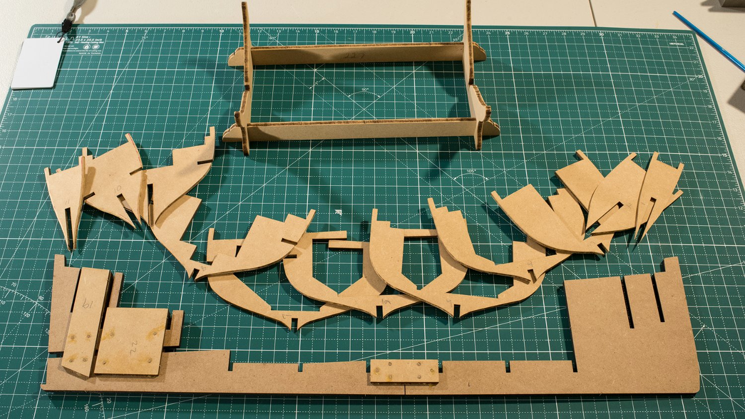
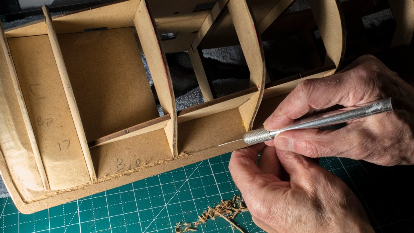
Next, I dry-fit as many pieces as I could to see if there are any problems before I start gluing. And I found several. Dried wood glue cause several of the frames to not fit and fit crooked, and one of my clamps (part 19) was aligned slightly aft by 1 mm causing ½ of the deck (Part 32c) to not align with the other half, (32d). I disassembled and sanded several times. In previous boat builds I have had trouble with slightly skewed frames causing extra work with planking and deck work. So, one of my lessons learned is to be very careful in the early stage assembly. I’m sure I’ve missed something, which can be fixed later, but I’d rather build it “square”.
-
The keel came in 2 pieces that are to be glued together via clamps and dowels. I sure appreciate reviewing the other build logs of this kit, as they help guide me. For my heavy sanding, I use my spray booth enclosure built in my garage. This setup exhausts air outside through a window and includes a filter in the booth. I also used a personal N95 mask and gloves. Most of my dust was created in beveling the fore and aft bulkheads along with sanding the worst of the laser char off the surfaces that will be glued. I will do a more thorough sanding job on surfaces with laser char that will show after assembly, such as the cradle, so that paint or varnish will not be affected by a rough charred surface (looks nicer).

-
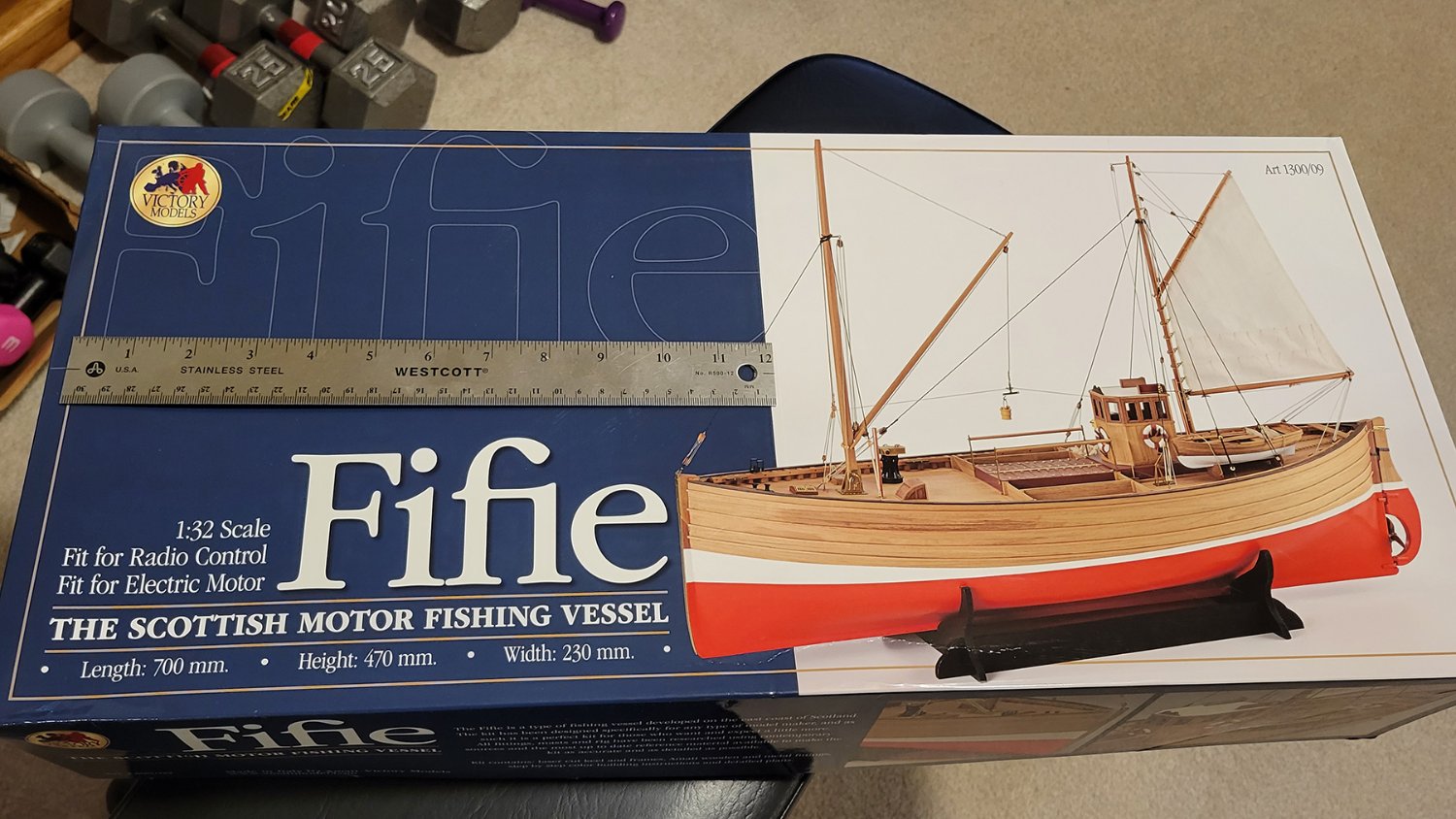
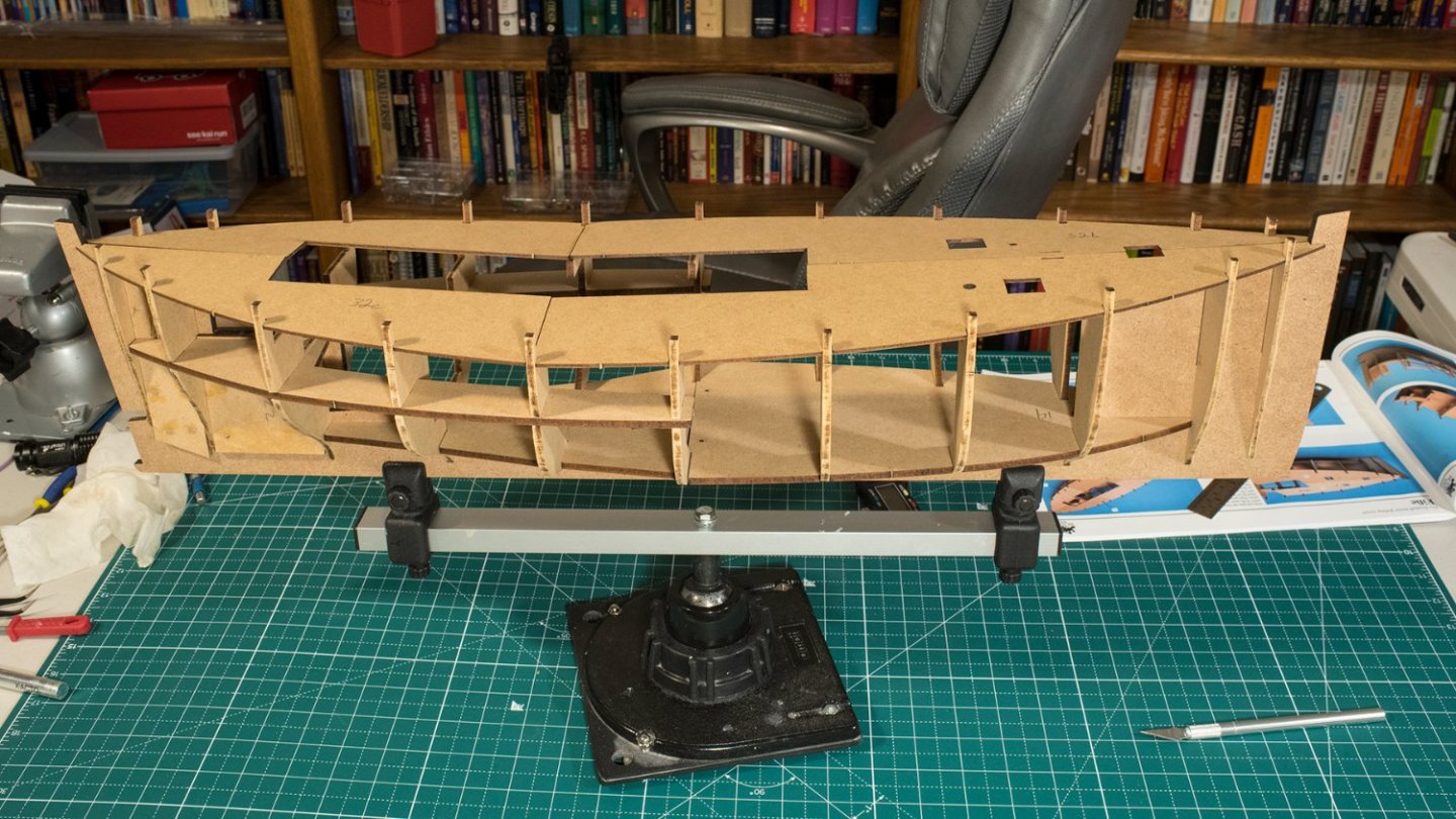
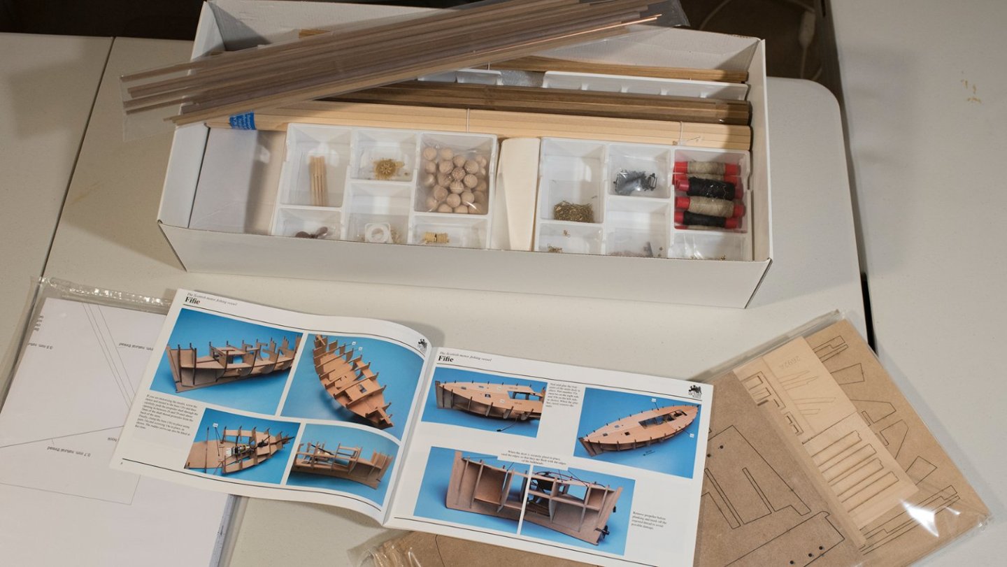
The Fifie is a design of sailing boats that was a traditional fishing vessel used by Scottish fishermen from the 1850’s until well into the 1900’s. Their vertical stem and stern, long straight keel and wide beam made the Fifies very stable in the water. In the 1900’s many were converted to motorized craft. As and aside, this model will be the longest boat on my shelf when I am finished (at 27.5” long by 18.5” tall and 9.1” wide). As I progress in my boat building hobby, I am beginning to wonder where I will put all the boats I have built, and plan to build. I would like to know if you people are displaying all of your boats? I’m thinking my early creations will end up in a box in a closet, and my latest will be placed - . . . I don’t know where! . . . since I am running out of shelf space. The previous models are collecting dust, and I would like to continue building for many more years. I guess I will have to either buy enclosures or learn to build them. Still, the question stands - as to where I put them. Since the Fifie is larger than my previous boats, I need to determine my storage/display strategy very soon. I would like to know what all of you are doing with your boats! Back to the subject: the Kit itself looks like a quality set of components and instructions (so far).

-
kit review 1:32 Fifie – The Scottish Motor Fishing Vessel by Amati
Ken_2 replied to James H's topic in REVIEWS: Model kits
This is a very nice-looking boat! Ken -
You are making good progress! Ken
-
Todd, Bruce and Dsmith: I will follow along with all of you as well. I will be starting my build of the Scottish Fifie in early January. Ken
-
I just pulled the Scottish Fifie off of my shelf and I am planning to start assembly in January. I found your build log, and I find it most instructive. Your pictures are wonderful, and I am sure you have already forewarned me about several problems I am likely to face (broken frames, wear a mask, etc). Thanks. Your boat looks great so far. Ken
-
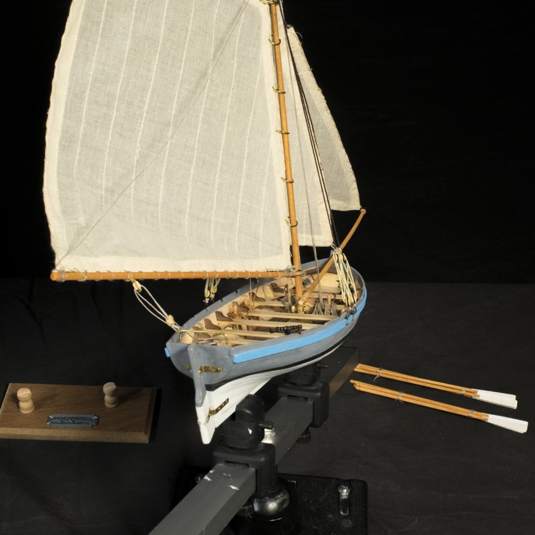
I have finished all the details that I have time for. I am calling this build log complete. 🙂 I will mount this boat later, using wood glue, which will take time to dry. As well, I will place the oars on-board. It’s been fun watching all the other boats that were built and are being built, and fun chatting with some of you. I will look you guys up in the future to see what boats you will be building. Ken


- 62 replies
-
- 6
-

-
- Bounty Jolly Boat
- Artesania Latina
- (and 1 more)
-
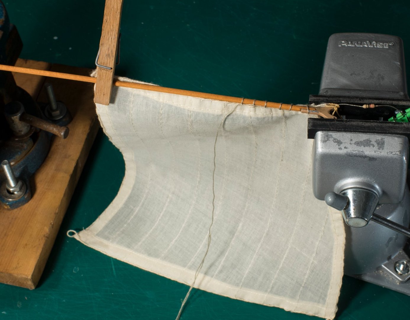
here is what it looks like so far. Now that I see it up close, I think I am working on the show side (or front) whereas I should be working on the backside. I think I will take out all the stitches (again) and start over. Dooh. But at least you can see how I am planning to attach the sail.
- 62 replies
-
- 2
-
-
- Bounty Jolly Boat
- Artesania Latina
- (and 1 more)
-
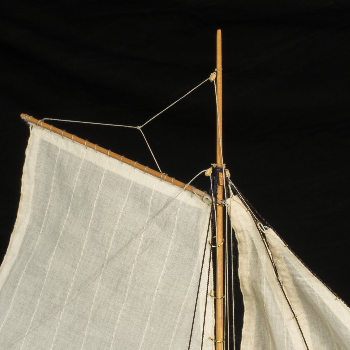
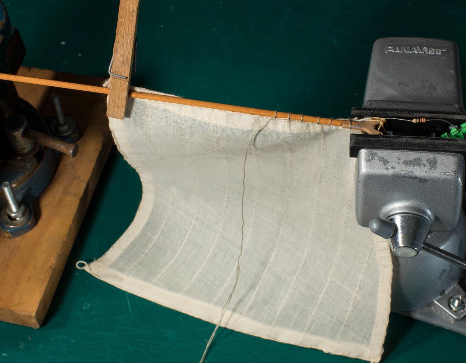
BTW, Kev: I am stitching my main on the gaff using the process described by John Aliprantis in the following link. This guy has a lot of videos!! and his > 15 ships look excellent. He must be a professional. How else could anyone find time to accomplish all of this? It took me a long time to figure out how to do this. He makes it look simple, but it was not simple for me (I must have two thumbs and apparently dyslexic 🙂) https://www.youtube.com/watch?v=gVYStQmDinI&list=PLmoS1cmOImghy14MocWkRNTHDQtmMnA-f&index=77 Ken
-
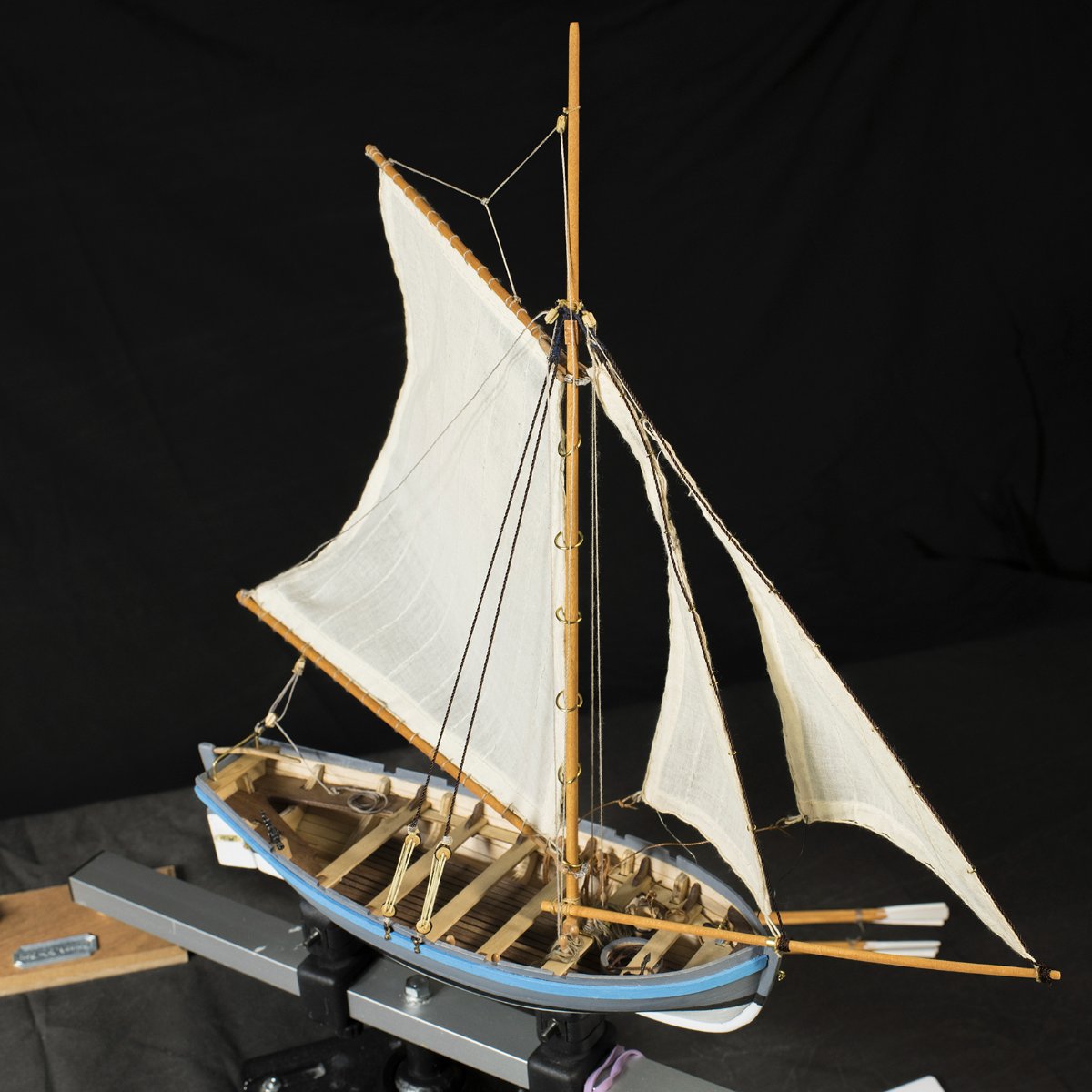
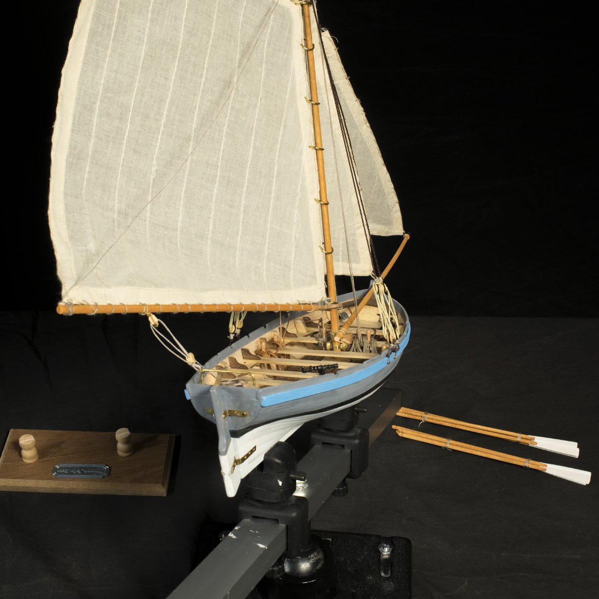
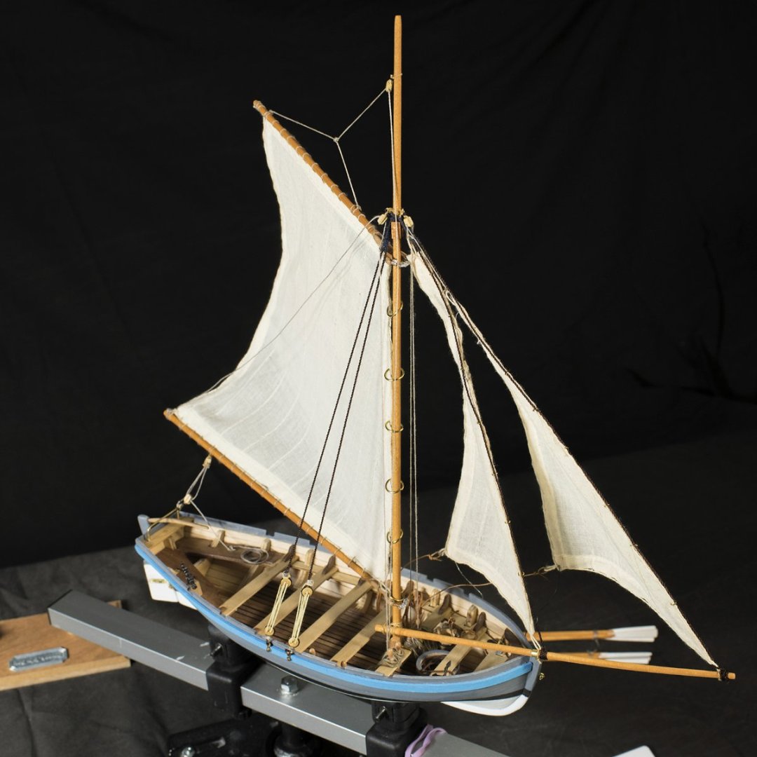
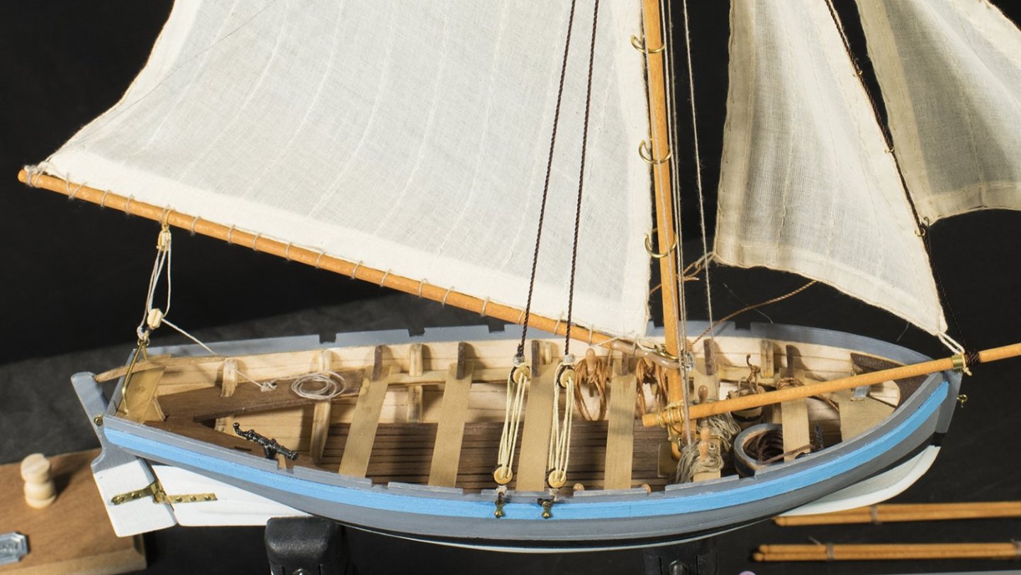
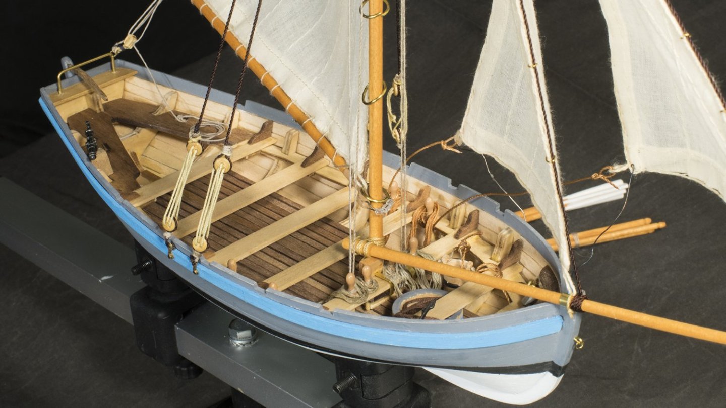
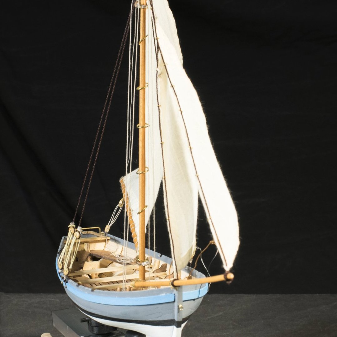
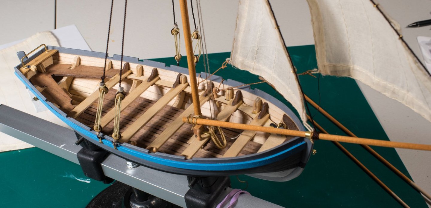
Kev, here are some photos. Sheets, lines and knots take me a while to get right, so what you see is temporary for this photo. But I like the placement of the belaying pins. They are a bit large for the scale, but it is what I have. Ken
- 62 replies
-
- 3
-

-
-
- Bounty Jolly Boat
- Artesania Latina
- (and 1 more)
-
Allan: Thanks for your information on boat styles, oars, and rigging. I've been so busy working to assemble my kit while improving my skills, I've not really focused on the bigger picture. You are providing another aspect of model kits that I have not focused on. Keep your insights coming when you have time. Ken
- 62 replies
-
- 1
-
-
- Bounty Jolly Boat
- Artesania Latina
- (and 1 more)
-
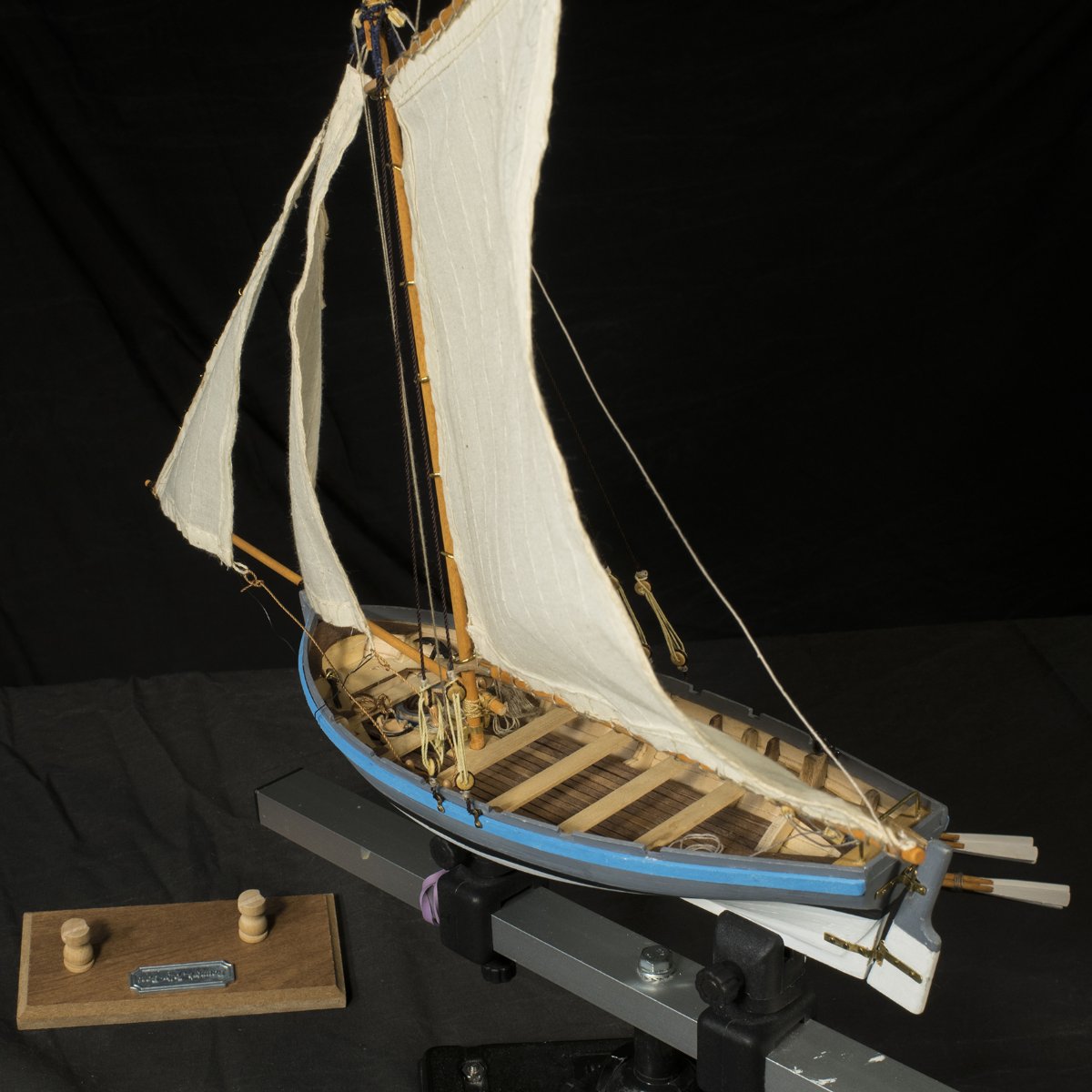
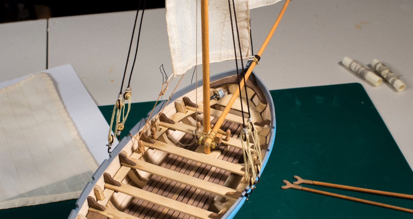
Kev: Thanks for your encouragement. Yes, I will post some closeups. Basically, I think the sheets should be lead as far outboard as one can, and far enough back for good leverage when sheeting in. I choose to place the belaying pins on the seats, since there were no other reinforced places. Sakcha added a wood platform, which is a really good idea, but I choose not to do this. I placed the 3 belaying pins for the halyards next to the mast, on the seat (sort of what you did). I see you waited for the good thread (boat lines) to be delivered, which was a good idea. Good line makes working on the rigging easier and it looks so much better. I was using existing line but I did not have the patience to wait for black line from a supplier. I would have used this black line to serve the halyards at the mast but, instead I used sewing thread (and too much). Not the best choice nor best result on my part. I've not had much experience with serving and I look at my work as a great learning experience. Next time, I will do better, and know more. 🙂 Ken
- 62 replies
-
- 1
-
-
- Bounty Jolly Boat
- Artesania Latina
- (and 1 more)
-
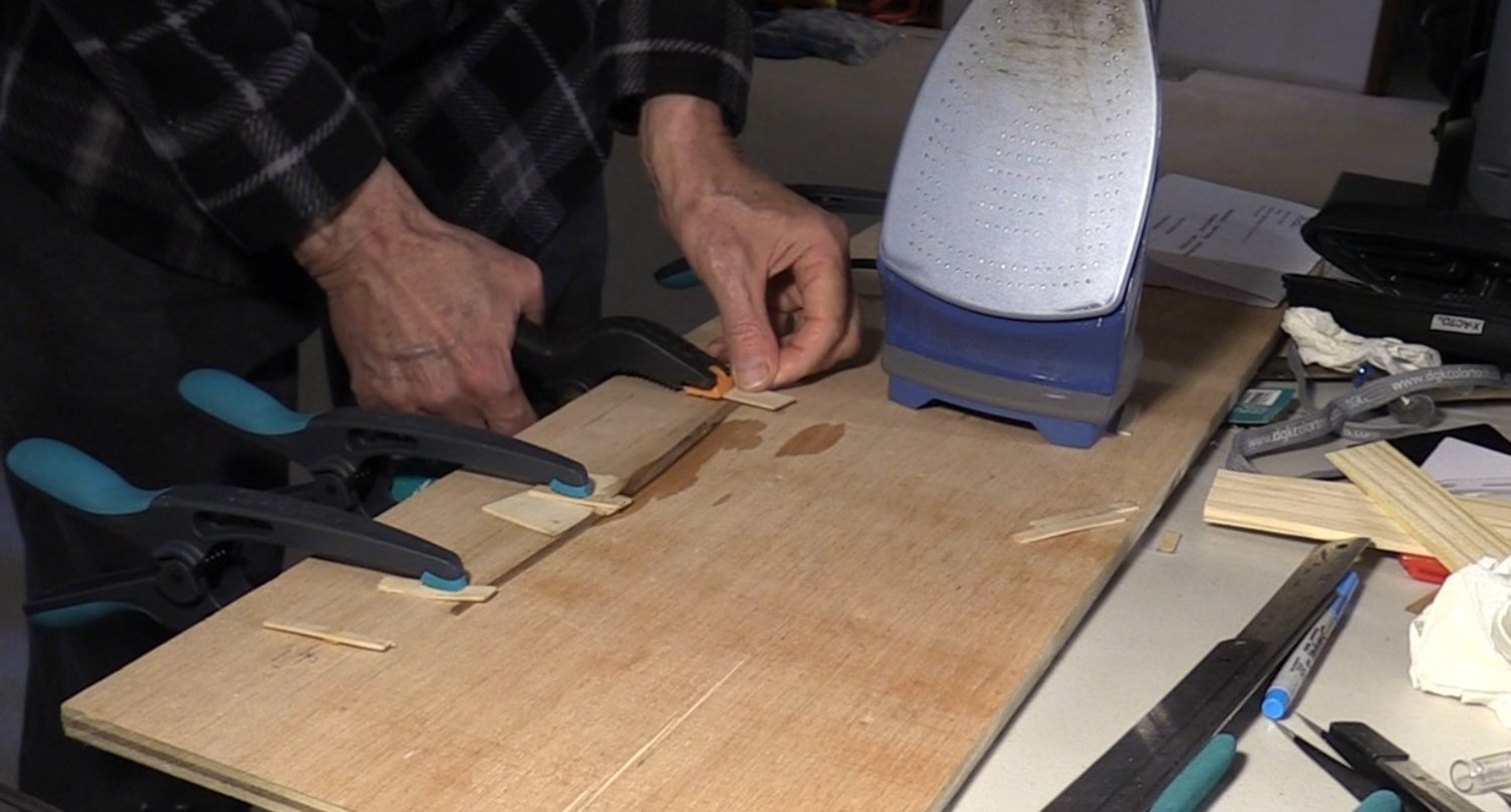
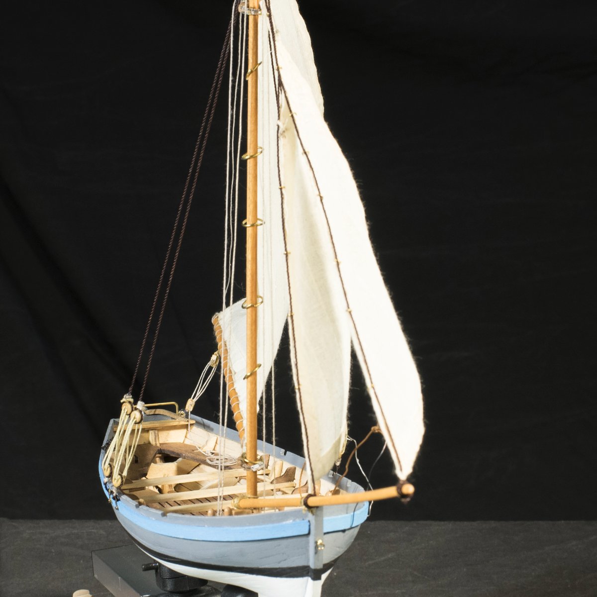
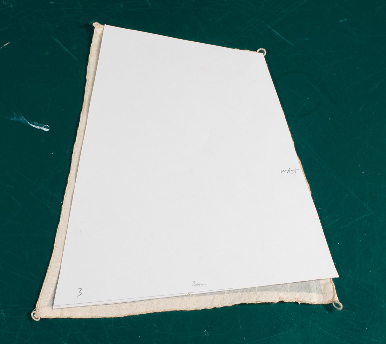
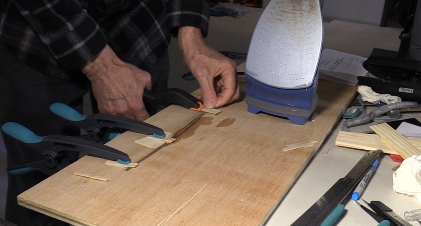
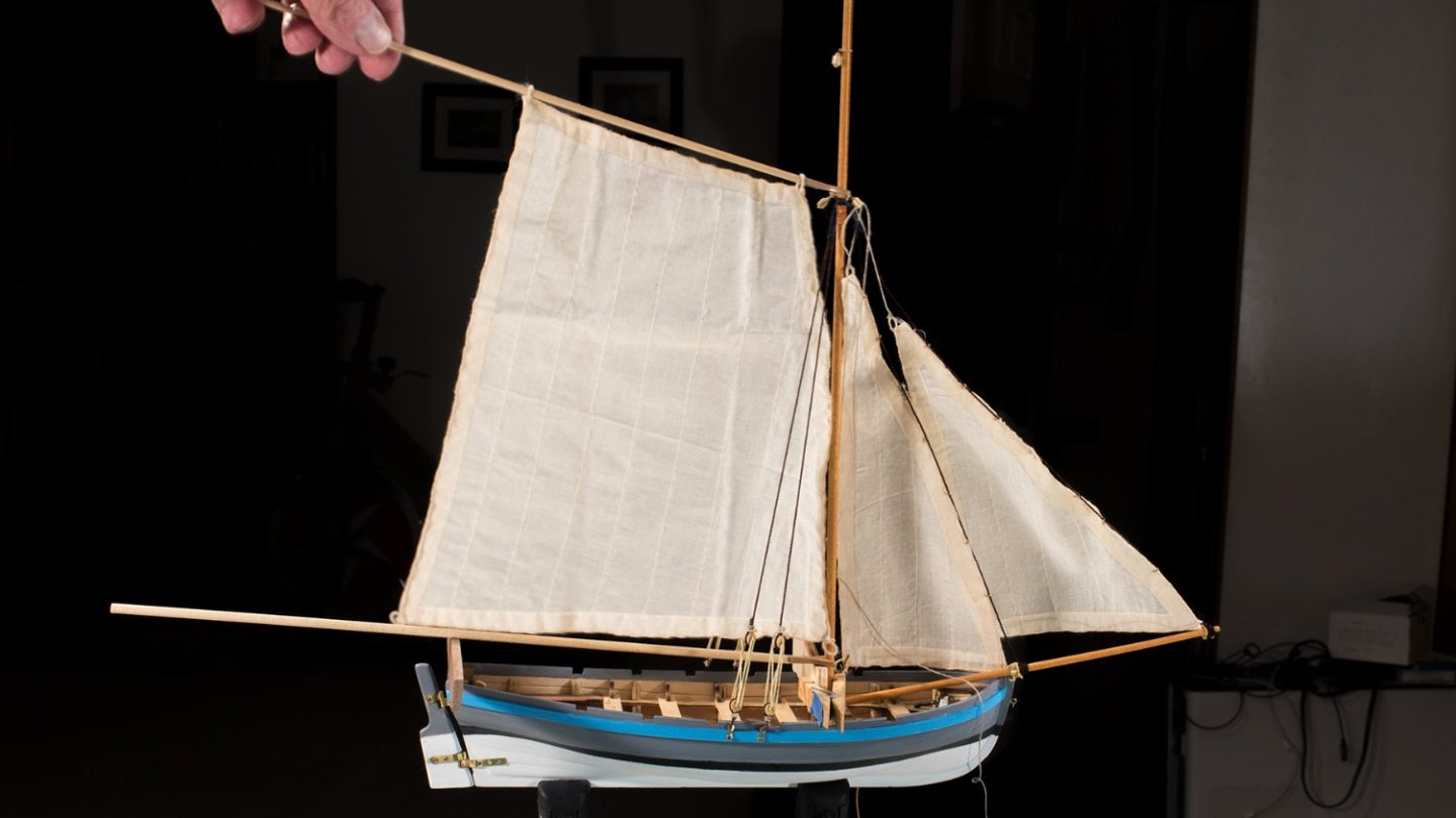
Next, I tried to hoist the main sail. But it was too large, as others have noted. With the boom as low as it can go, the gaff rides right at the level of the cleats. Since I wanted the boom off the deck, to represent room for the crew to move, and as shown in the pictures, it rode even higher. So, when I lower the gaff to be below the upper rigging, the main sail really sags at the main mast. My wife offered to shorten the mainsail, so this is my plan (aren’t I a lucky dog?). I cut a piece of cardboard to represent the size sail I wanted, then overlaid this on the sail trying to figure out where to cut, shorted and re-stich. To get a good estimate, I had to iron the sail, which made a big difference, and recut the cardboard several times to get it right (I hope). We decided she only needs to cut the bottom, even though the front is not straight and the trailing edge is longer than my cardboard. The goal is to get the sag out because it is too high. I'm thinking the boat will be complete very soon.

- 62 replies
-
- 1
-
-
- Bounty Jolly Boat
- Artesania Latina
- (and 1 more)