
My Fathers Son
-
Posts
259 -
Joined
-
Last visited
Content Type
Profiles
Forums
Gallery
Events
Everything posted by My Fathers Son
-
The gig turned out to be too below par due to the transom being twisted. Had to start again. Did much better this time. It's a good job it has turned out better as the model was stuck to the former and I had to break it to get the model off it. So next is the first lifeboat. I will have to prebend the stakes on this one. Simon


-
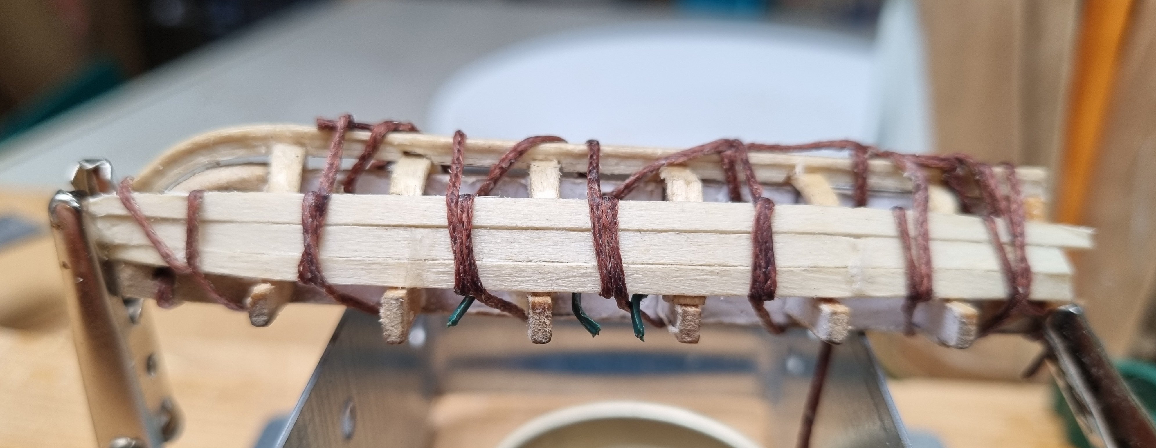
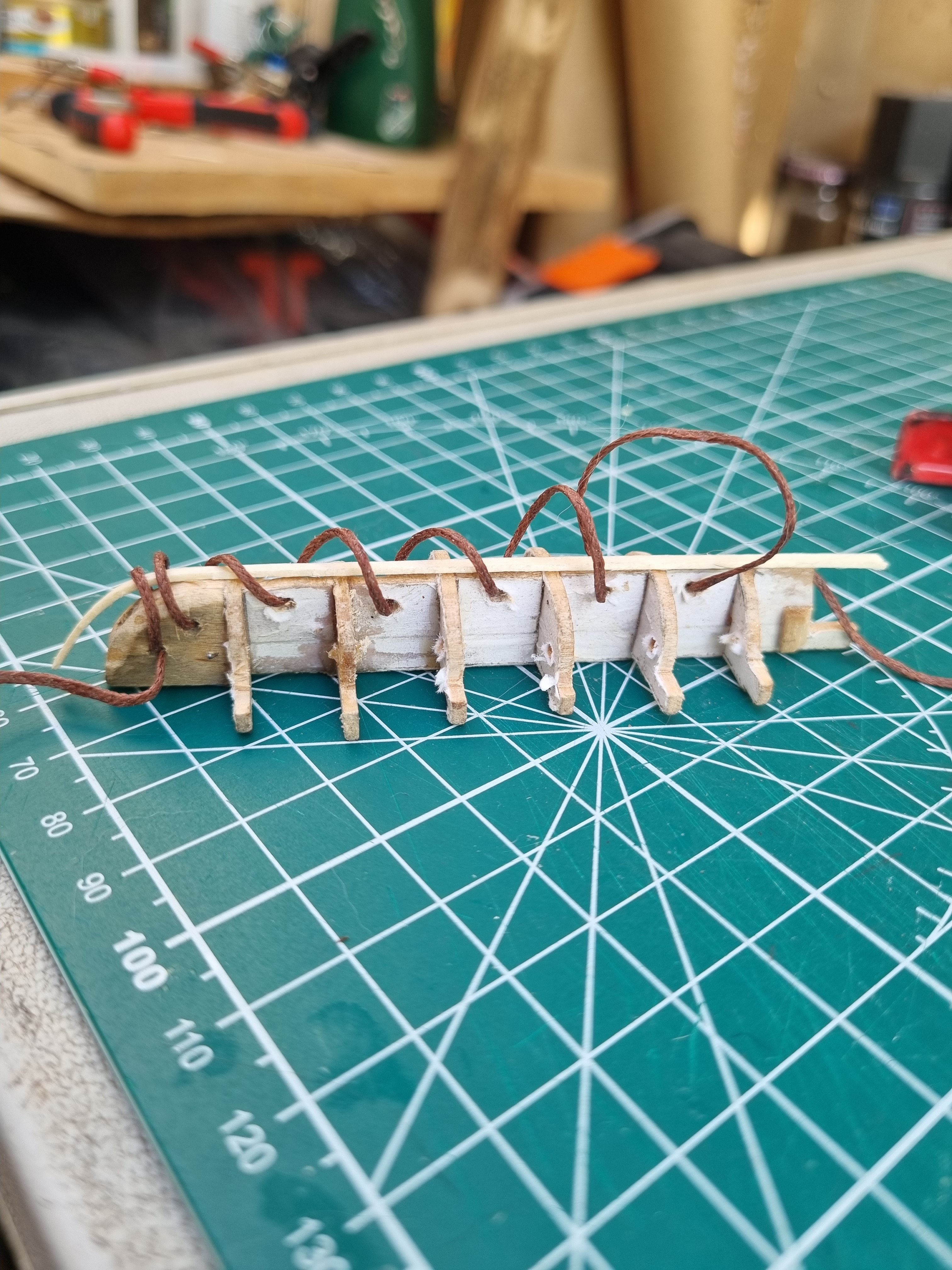
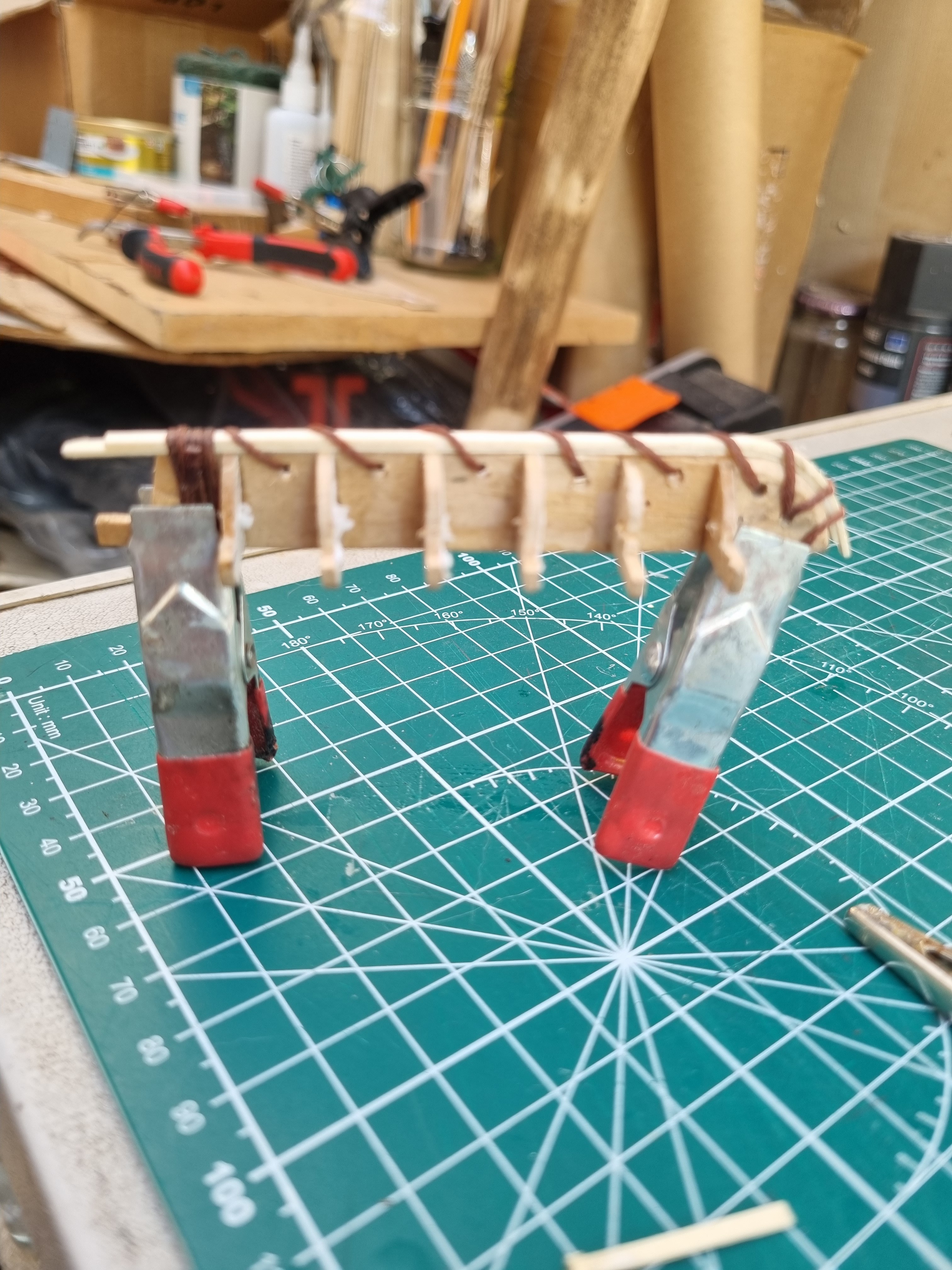
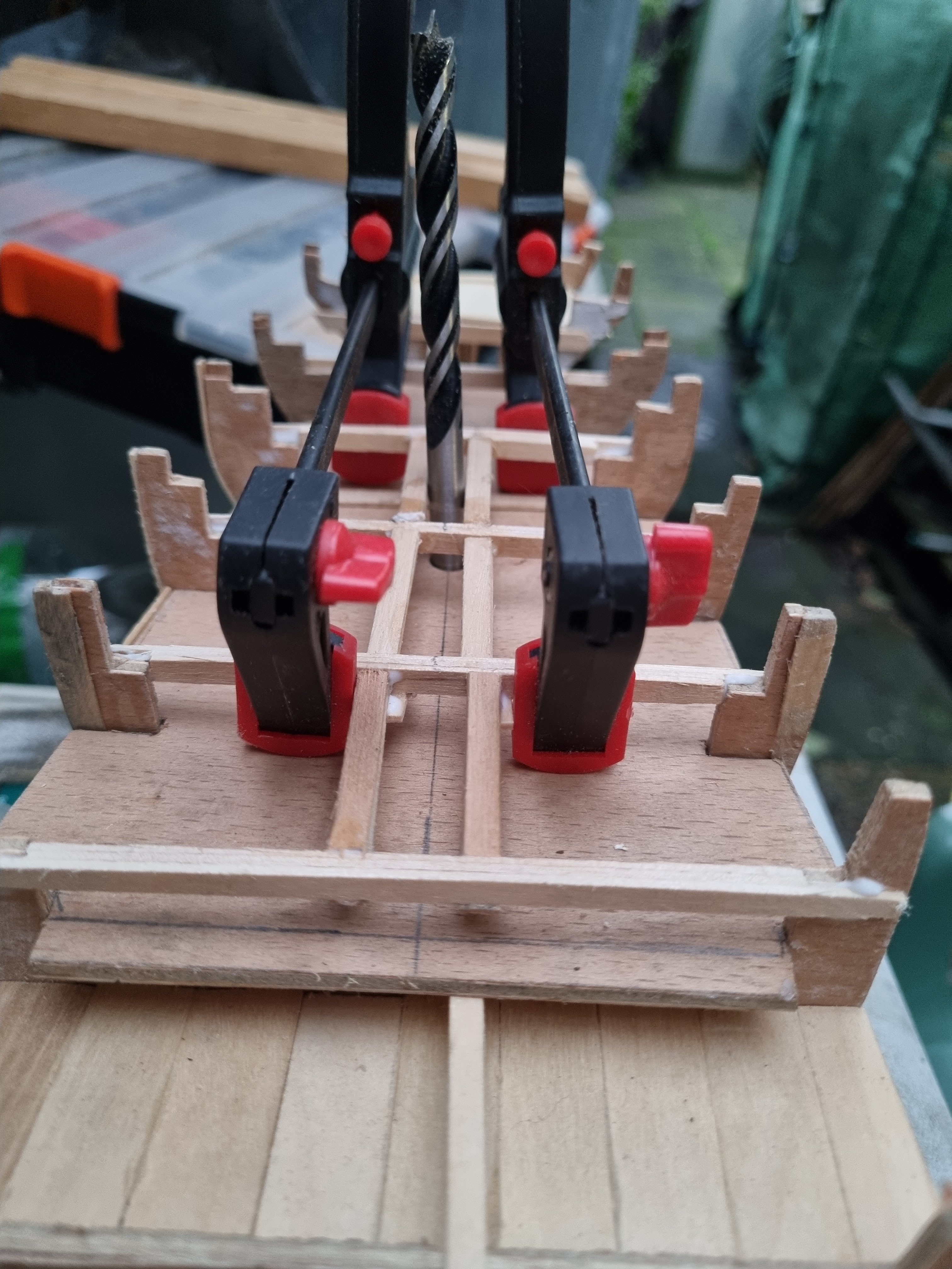
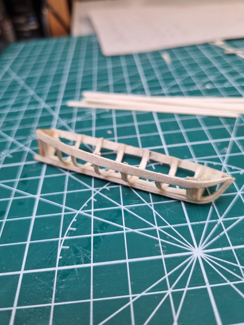
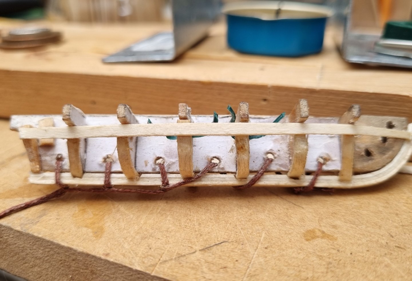
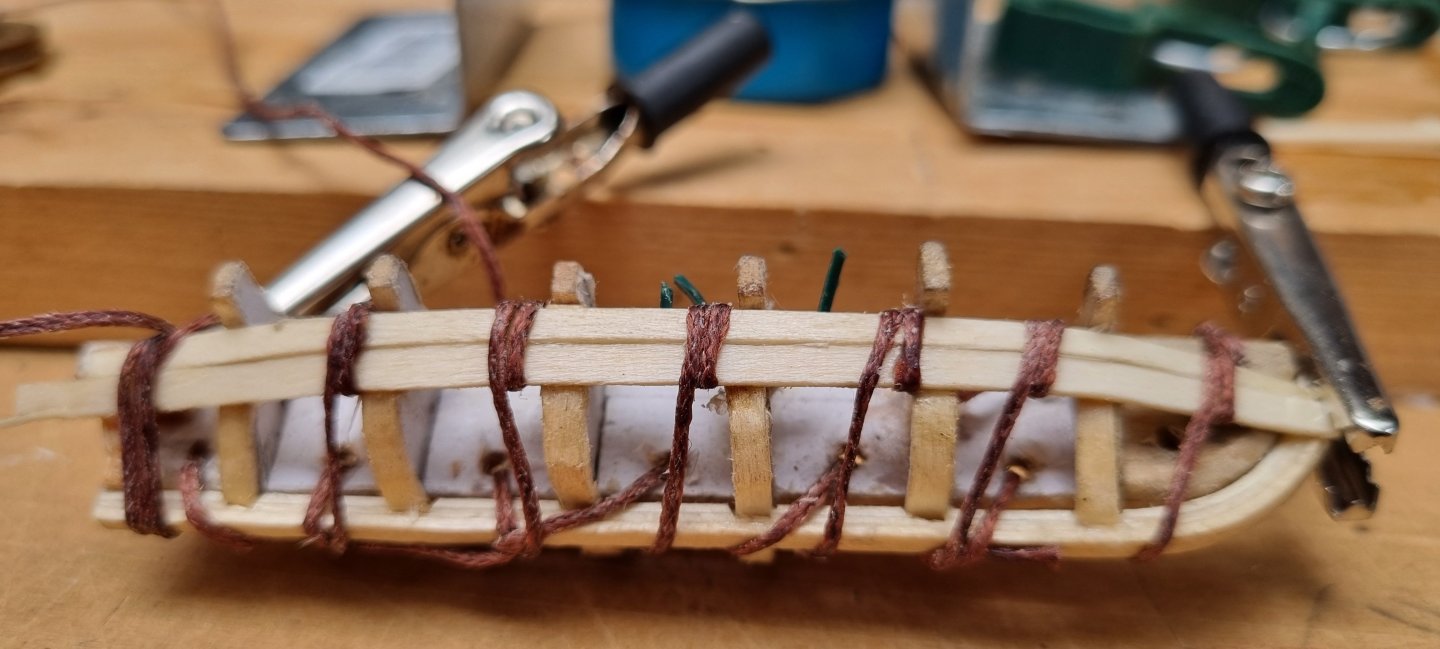
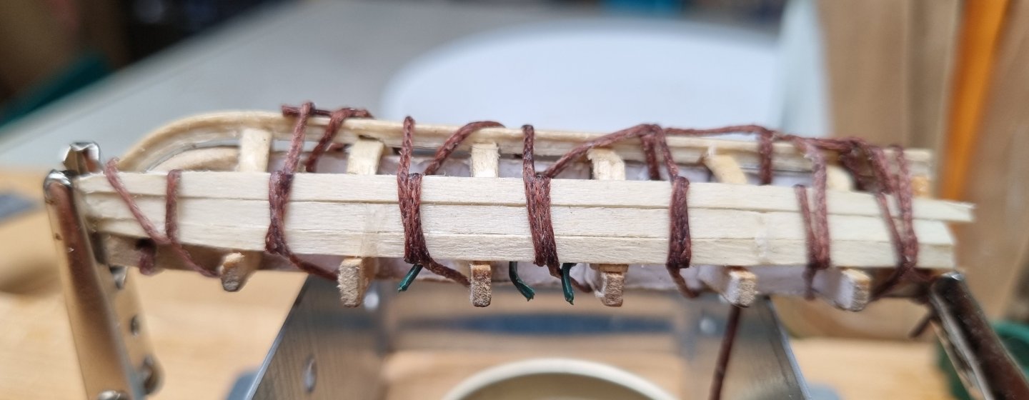
Last night I laminated 3 strips together to create the keel. I have drilled holes in the former and am using the same cord as I am using for Stays on CS. This is prewaxed but I have run it over my beeswax block for good measure. I have then secured the keel to the former using a simple running stitch. This will not get in the way until I have to do the final 2 strakes on each side but by then, the boat will be pretty solid in its shape. The top most strake has been secured on both sides. I know I say "you can't have too many clamps" but in this instance, clamps are not working for me. I saw a video the other day of someone building a canoe (full size) and he strapped each longways strake to the ribs and this made me think, hence I am using cord. This is where patience comes in. Each time I lay down a fresh strake, I run a cord from a knot or clamp around the boat, this is then run around the glued in strake and the new strake to hold them together. The cord then is run around the model moving on to the next frame and rib and repeated until you reach the end, securing the end of the cord with a clamp. I then touch a small amount of ca glue between the strake and each rib. You then have to wait for the glue to set up. So wrap, glue, wait, repeat is the order of the day. I am trying not to mess up the planking so here are 4 strakes cut and sanded to taper identically. Simon
-
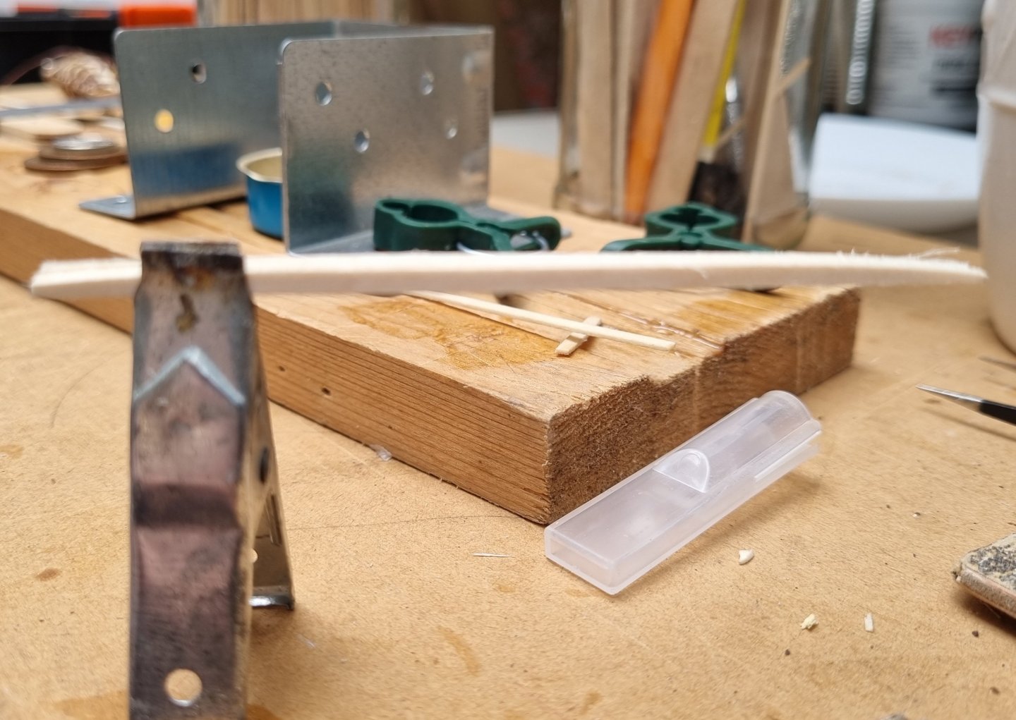
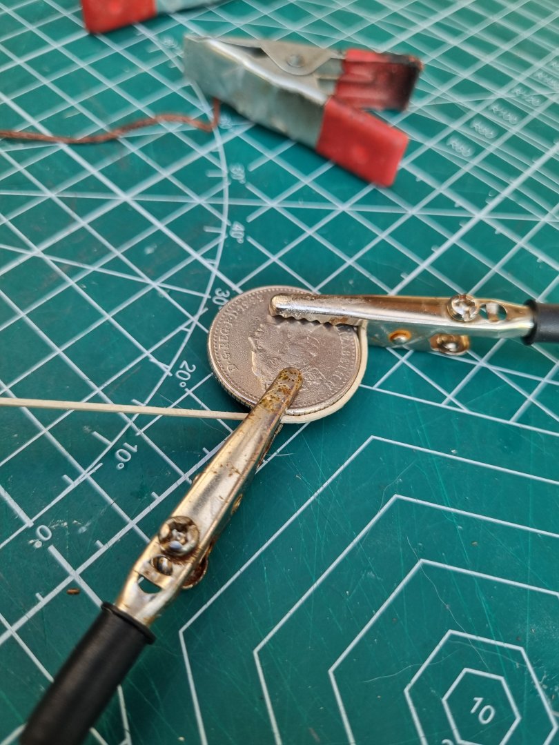
It's not bad but I am not happy with the Stern, the transom twisted. I am having another go at it. There is way too much overspill of glue for stain to be an option anyway but you are right, it would look good Stained, I can try this on the interior to see how this might of worked. I have started again on the Gig and on a new jig for the lifeboats. Trying different ways to secure it to the jig to see if that helps. Also experimenting with bending methods. Obviously, the coin gave the best curve and I used that to add the next lamination to the keel. Just need to find a coin the right size for each frame. Simon


-
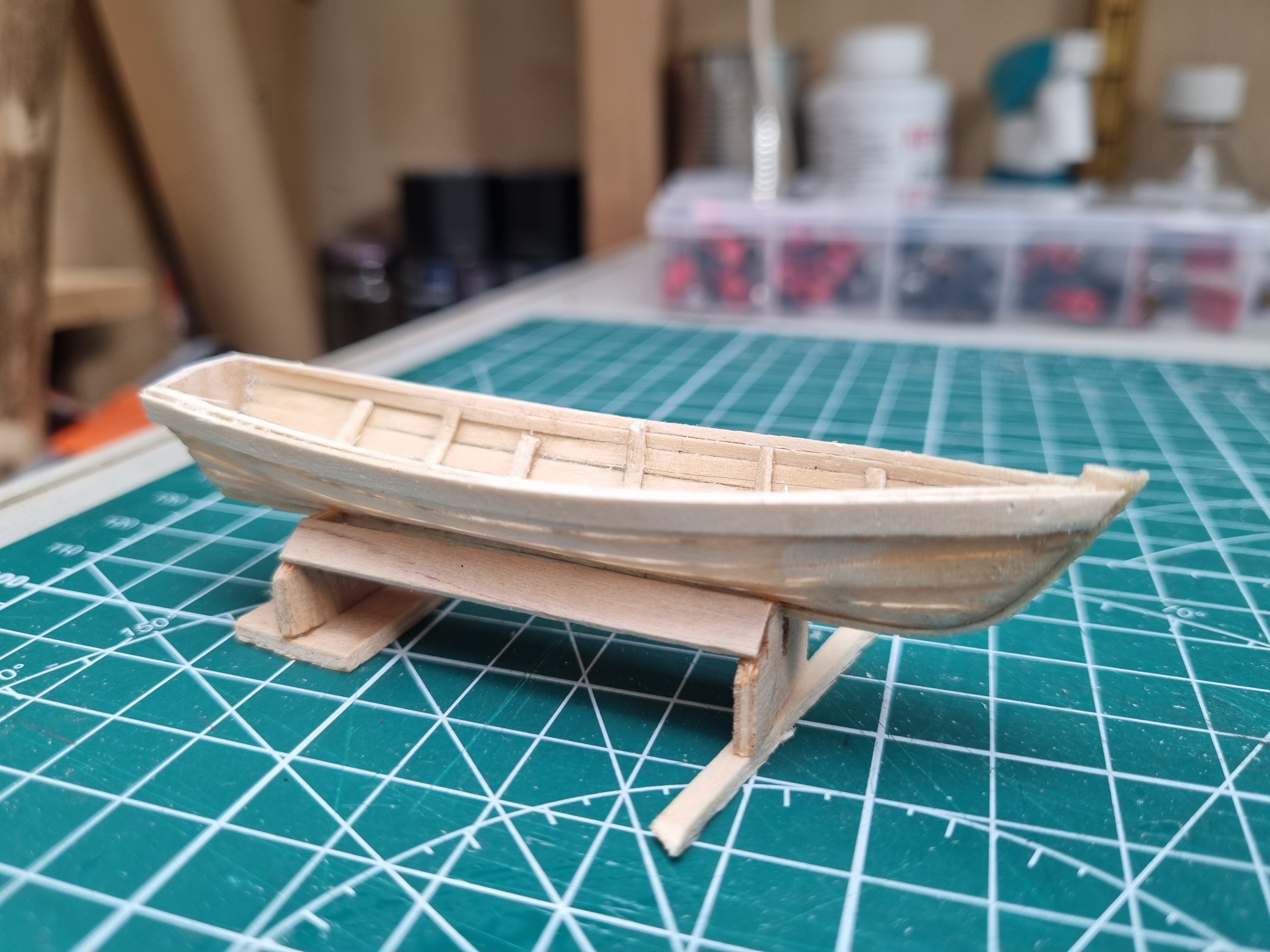
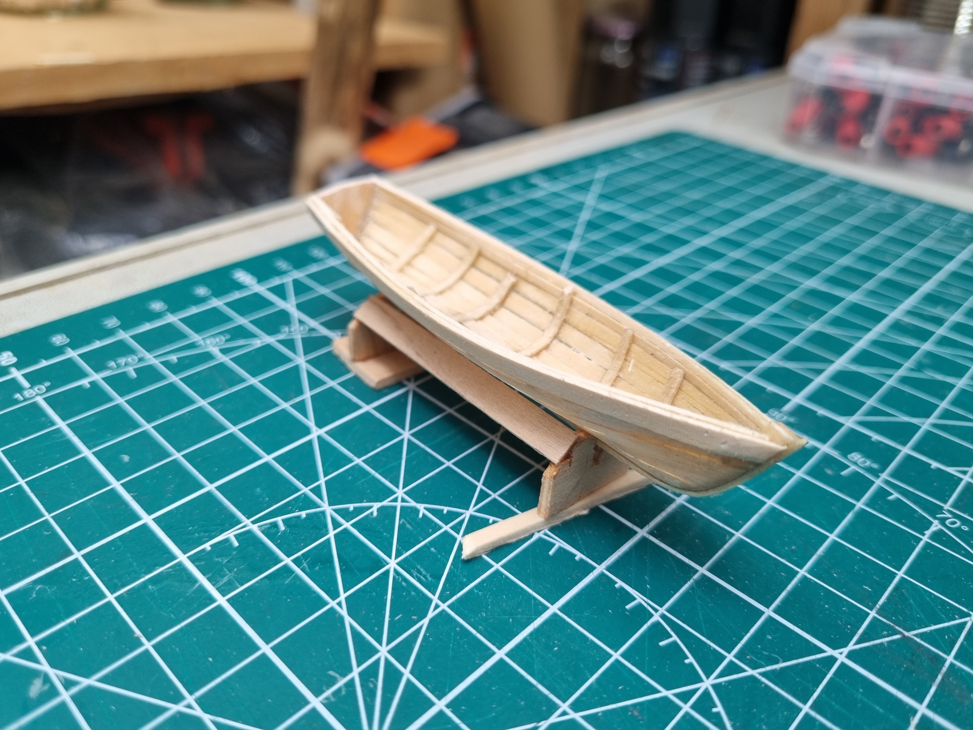
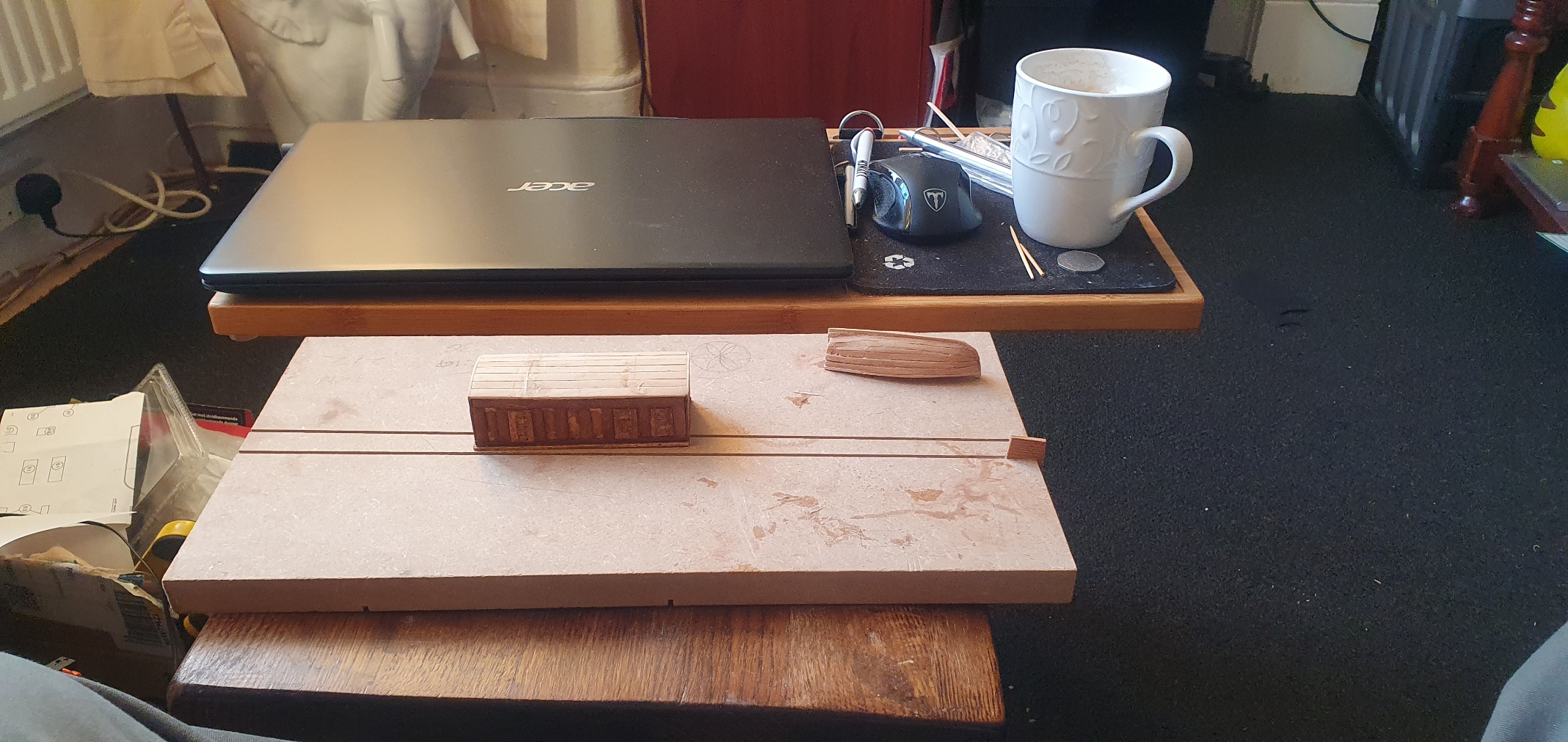
Ready for some paint. Simon


-
Indeed Rob, I also read that they were only able to create the forge down to a young stowaway who emerged from one of the ships boats who had worked in a smithy. Big T set the record for that year but CS beat it the following year. Soon after that they both became obsolete due to the opening of the Sue canal and the steamer became king. Simon
-
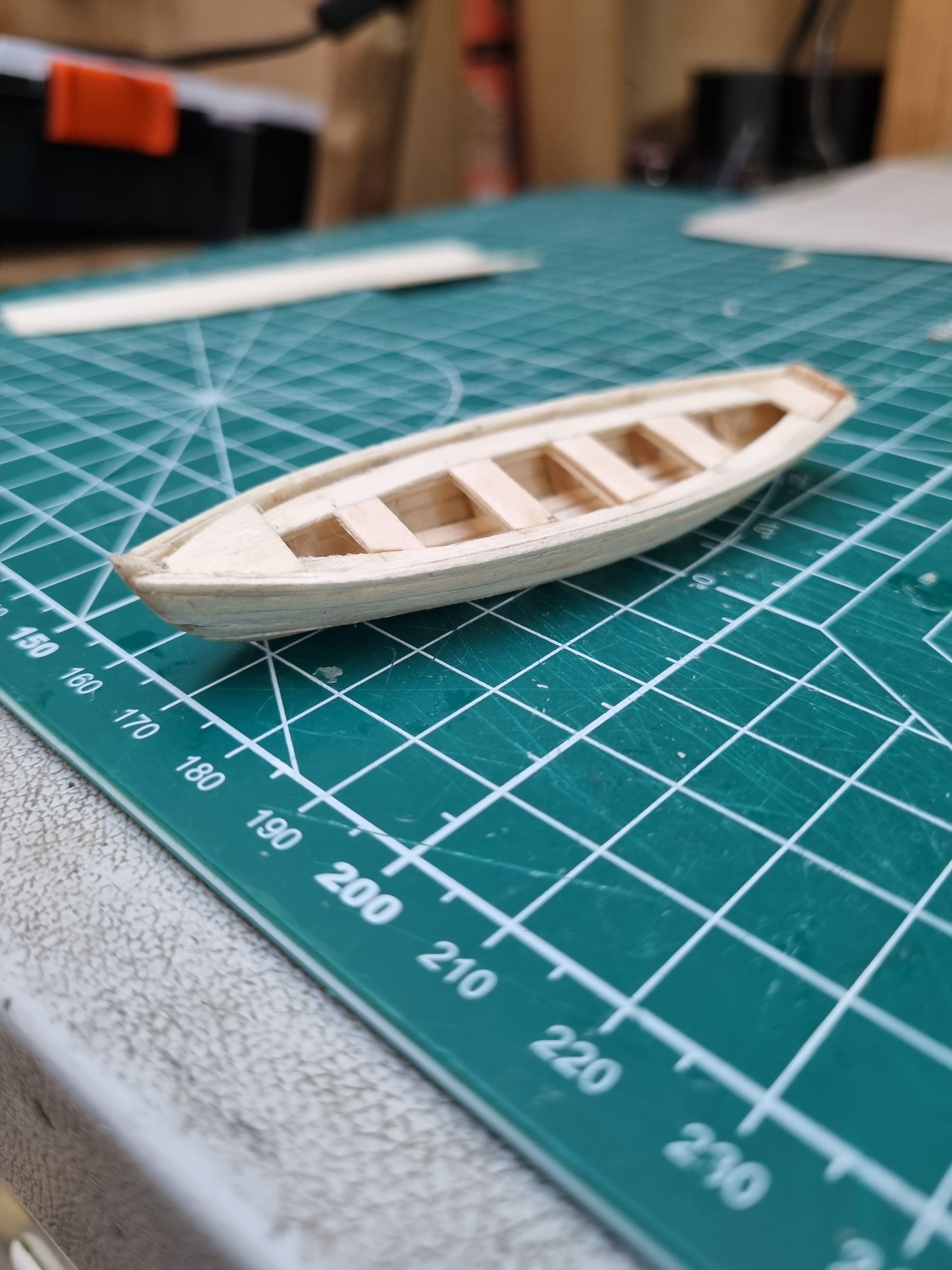
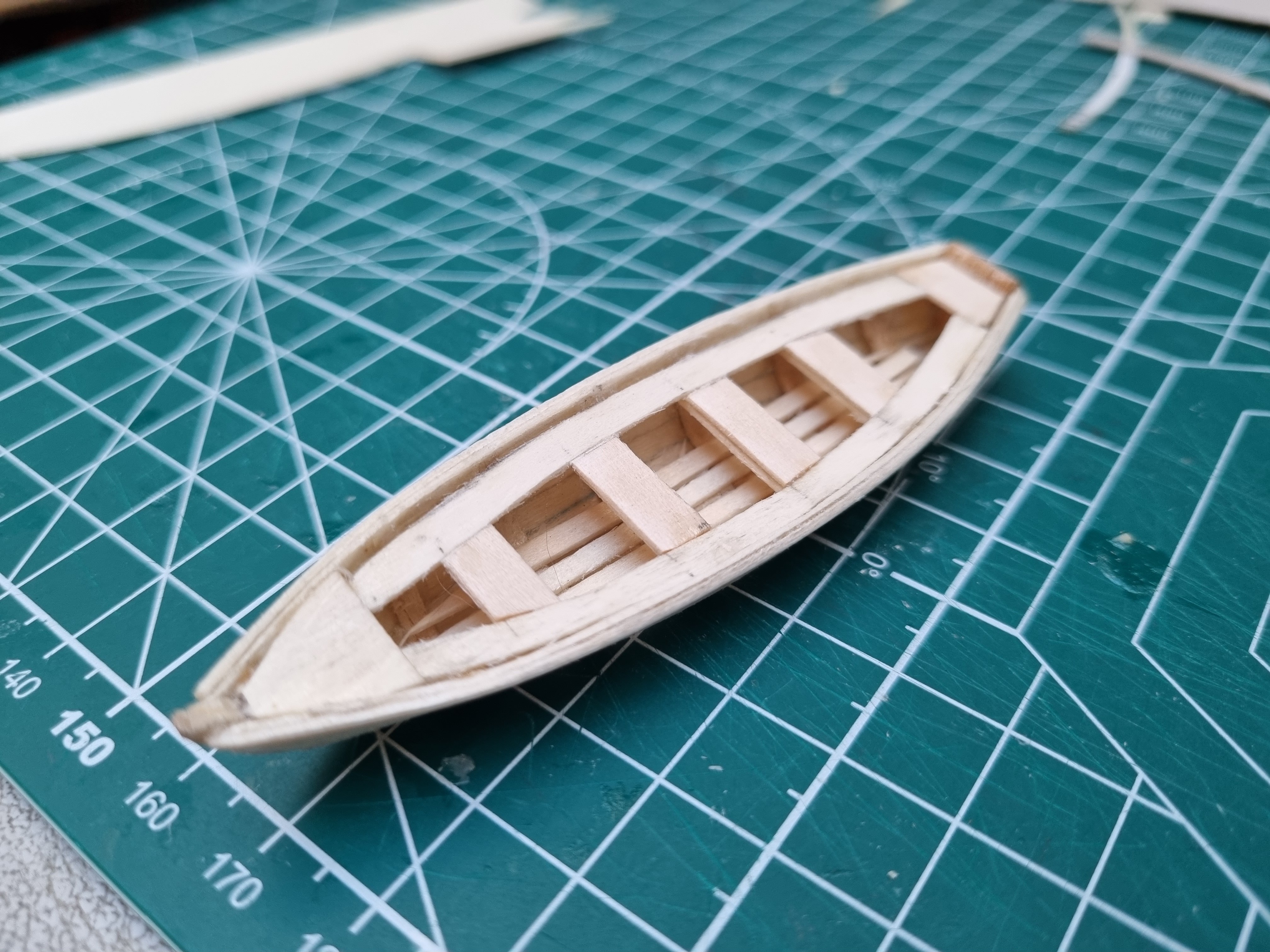
Made a little progress on the Jolly boat this evening. Just needs a bit of a rub down and a coat of paint before I fit the boards and seats. Too small for me o fit rollocks. This will be mounted up side down so nt much point in going in too much detail. Simon


-
I agree, I saw that on the small mock up I did as a practice, it's a bit like the difference between a 2 stroke engine and 4 stroke. 2 strokes are all about torque and acceleration but can't keep it up, where as 4 strokes are about stamina. Take longer to get to top speed but when they do, can stay at that output until the cows came home. Having read up on some of their history, there first opportunity to go head to head, both left Foochow on the same tide but CS got to te pilot boat first. She actually got a cross the southern ocean first and was a week ahead when she was hit by a freak wave rounding the horn which ripped off her rudder. This gave Big T the opportunity not just to catch up but overhaul her and get back to London a clear week ahead of CS. Unfortunately, there is no way of knowing what would have happened in the lighter Atlantic winds on the journey North after rounding the horn if that freak wave had not caused a that damage. Simon
-
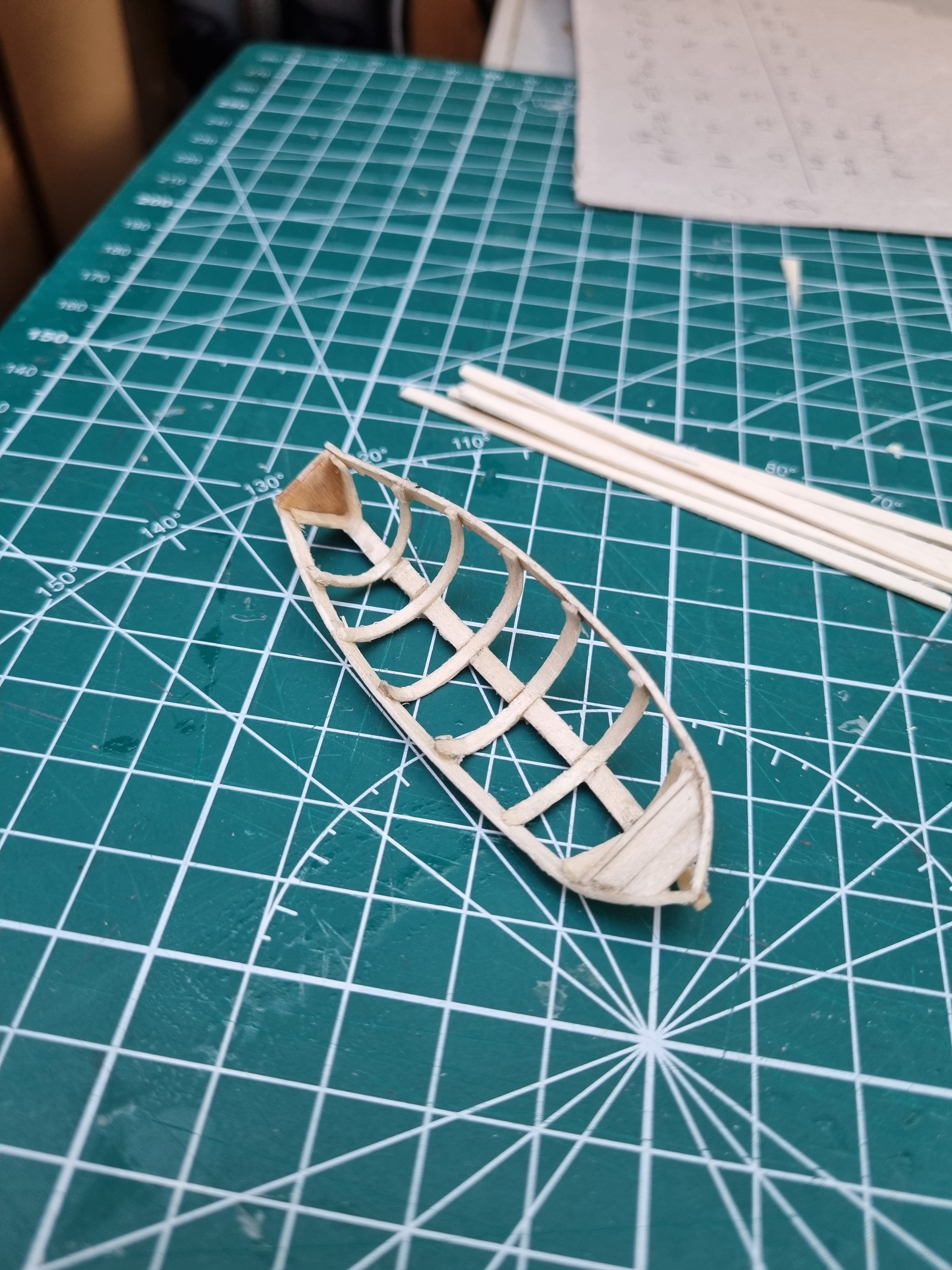
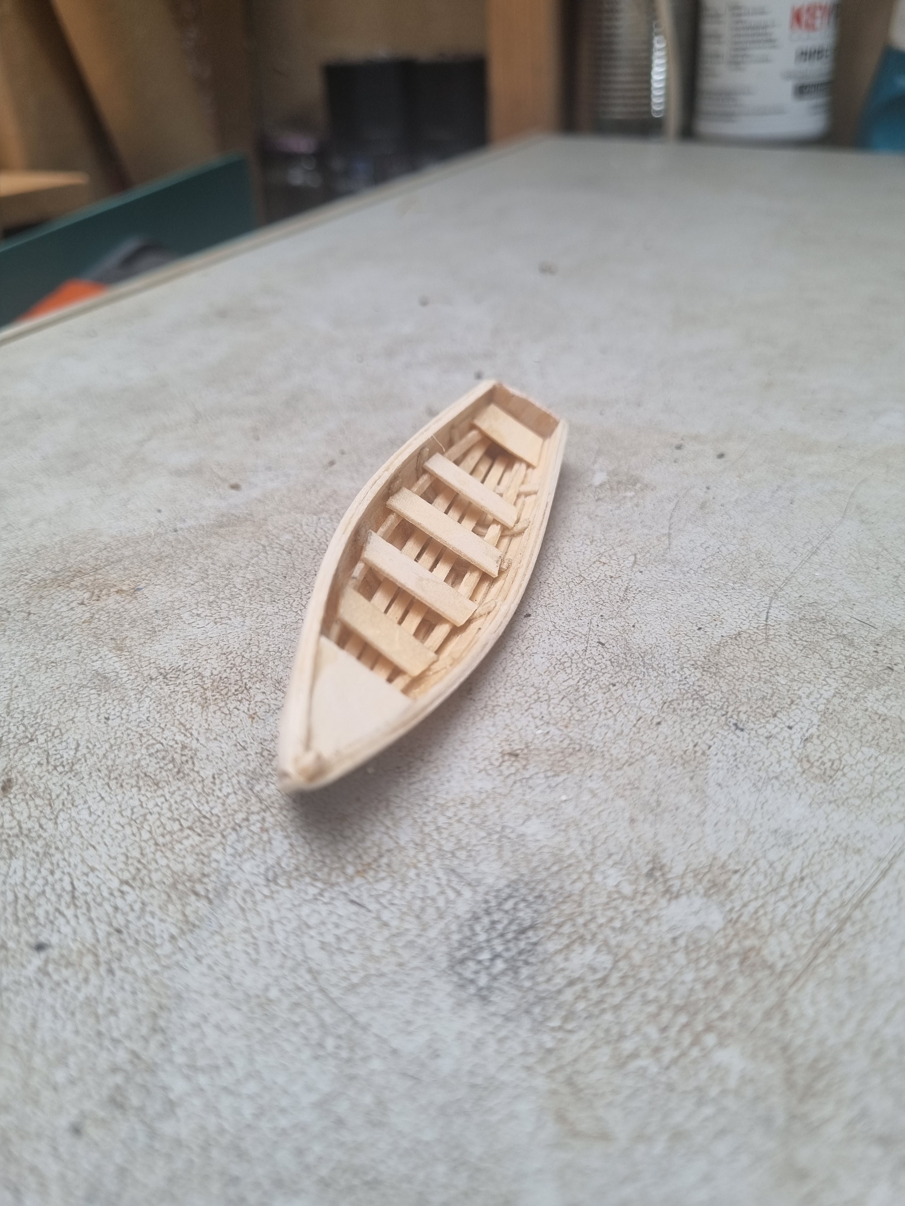
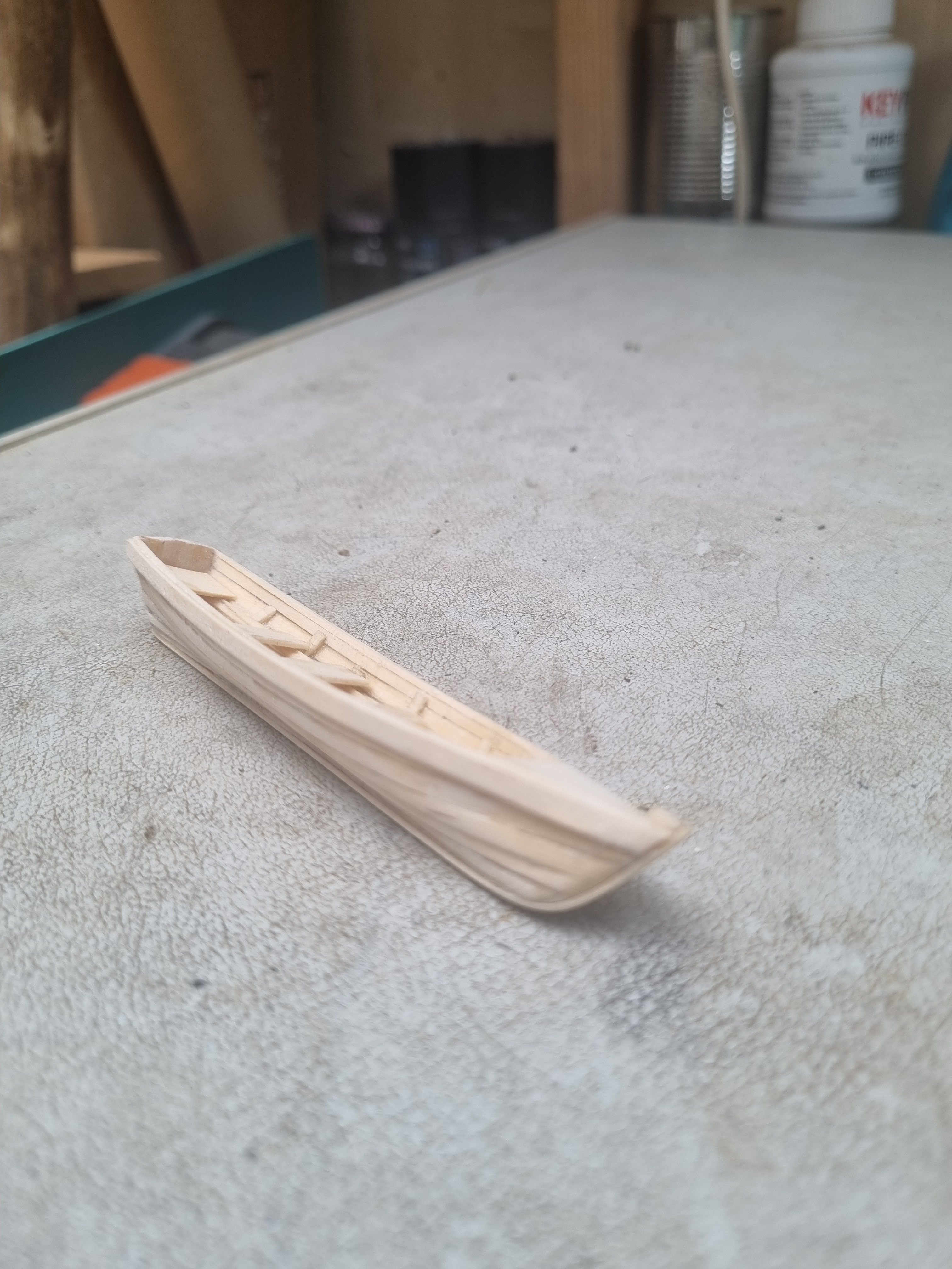
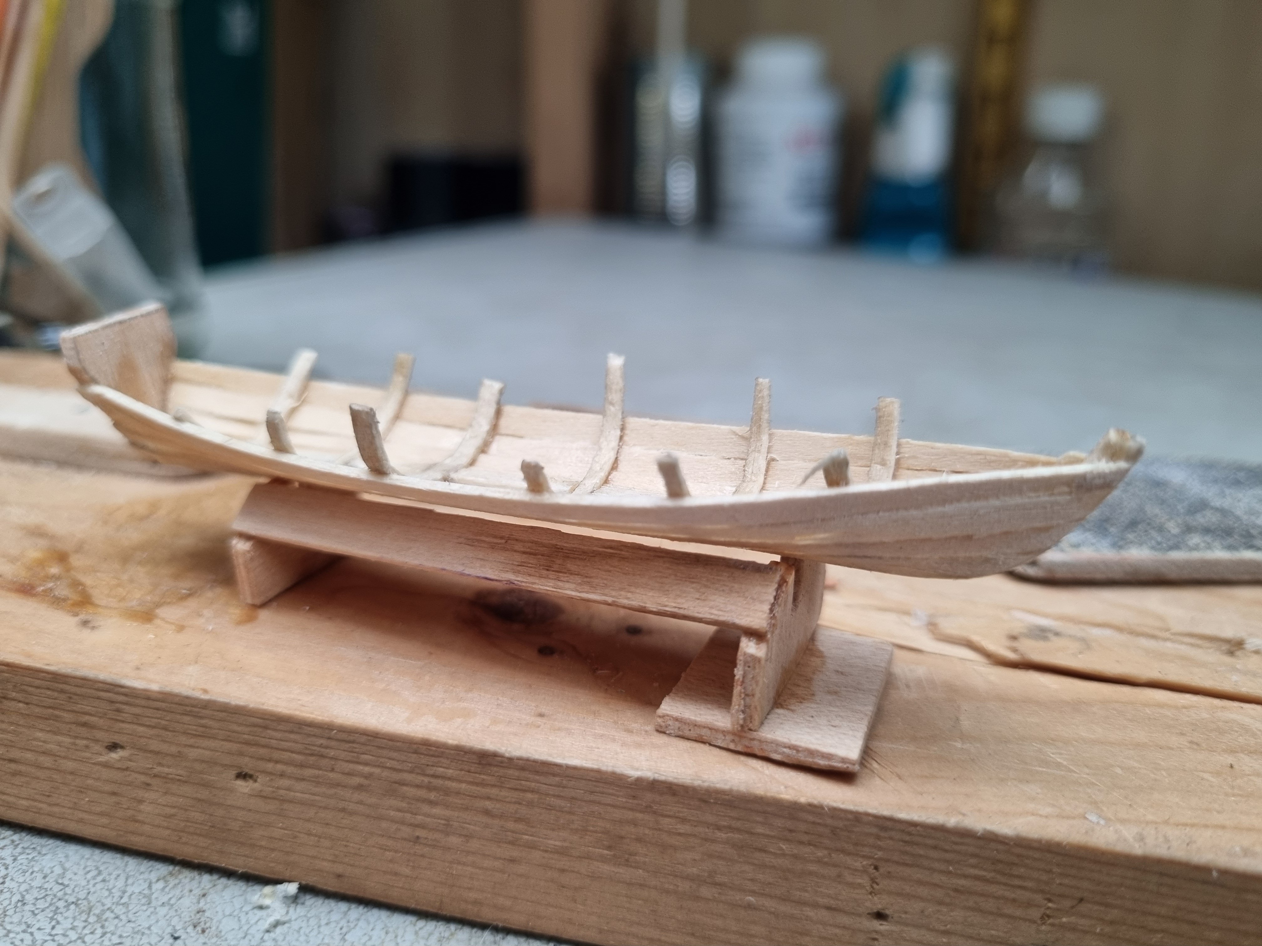
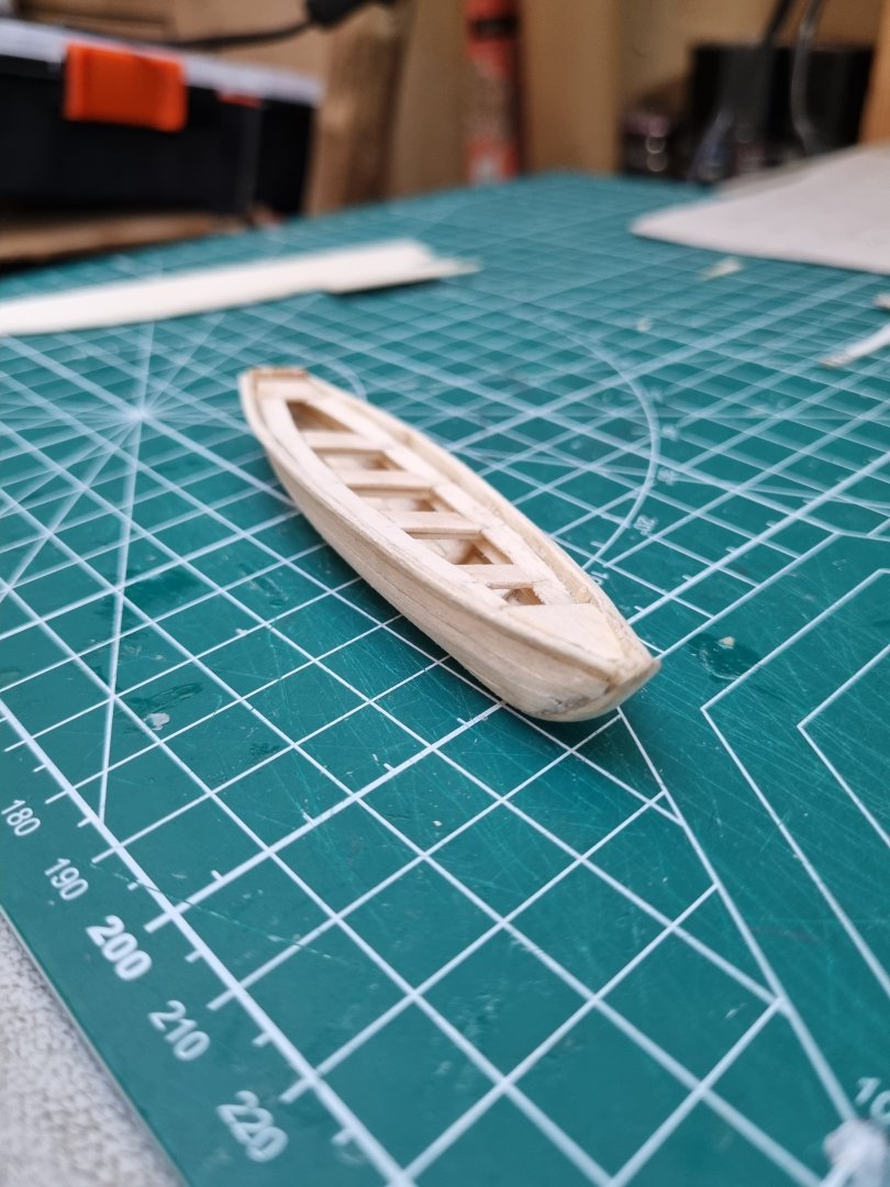
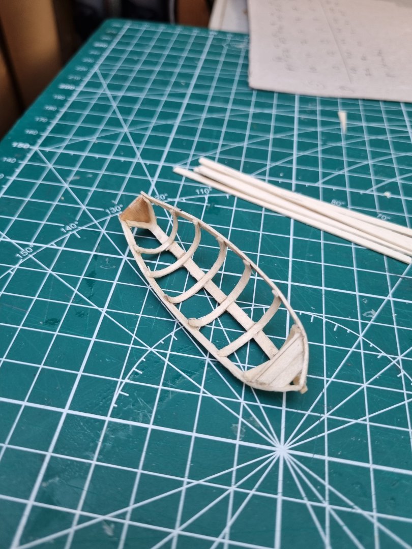
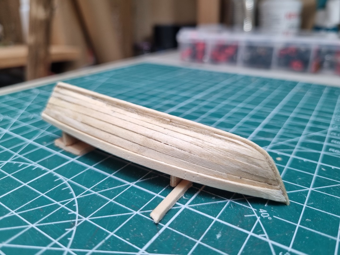
Took a day off from the main hull and started the jolly boat. I need a new jig for the life boats. This was originally constructed by creating the keel and then bending frames at strategic intervals with a notch in the inner edge of the keel for each one. I then stretched strake across the frames gluing only to frame and keel so it would come away from the jig. Now the shape is set, I can taper in the remaining stakes to pull the sides upright. I probable should have started tapering one strake earlier. At 90mm this is a litteon the long side for a 27ft ships boat but the smaller you go, it is proportionately harder to fashion and I should be able to fit this out with seats and boards, which would be a real test if it was just 10mm smaller. Simon

-
Rat lines are a good exercise in patients, I still have one mast to do on CS and I look forward to getting back to it but my furry friends are still way to interested in what I do. All yesterday, they sat within a couple of feet right next to me. Hate to think what they would do if a claw got hooked in any rigging.
-
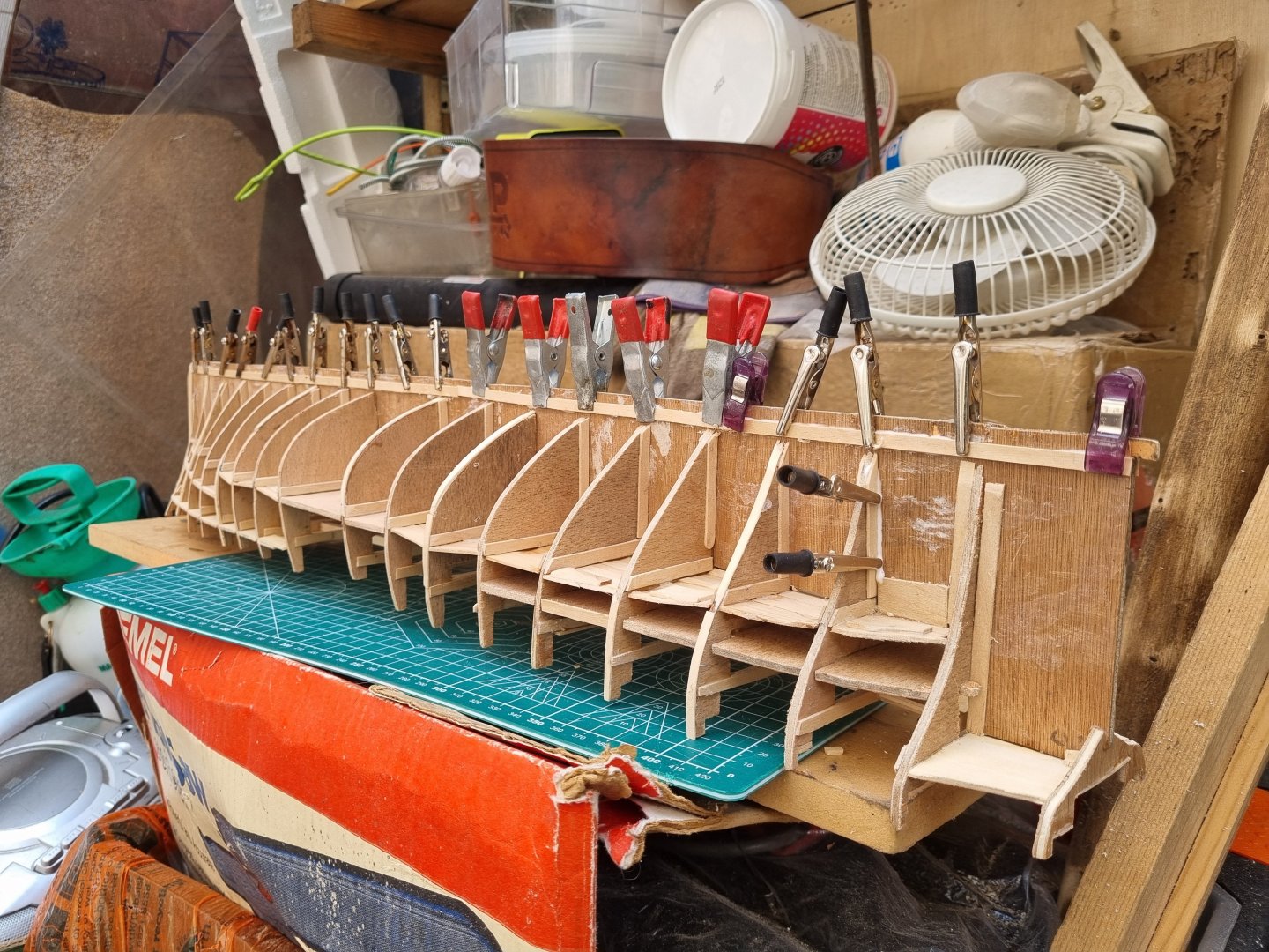
Seems like I spent hours on her today and you can't see the difference. What you can't see is where I have added additional wood to the bulkheads and then sanded them back to blend it in. Still not finished but I don't think that I need to add any more, just sand down and blend in the last ones. Still have the aft deck to construct and create the supports so the is no sagging. Still need to make my mind up on the material for the decks.

-
Bought more 1/16" basswood - - managed to cut out and glue the 'main deck in place

-
Rabbits set for first strake. Not ready to start planking but have run out of timber for decks. Plus this helps to show where I have to reduce or build up the bulkheads. I the end, there will be no plywood visible, it will all be planed over or veneered. Can't decide on mahogany or cherry for the decking. Hull will have to be painted anyway so not too fussy about that. Simon
-
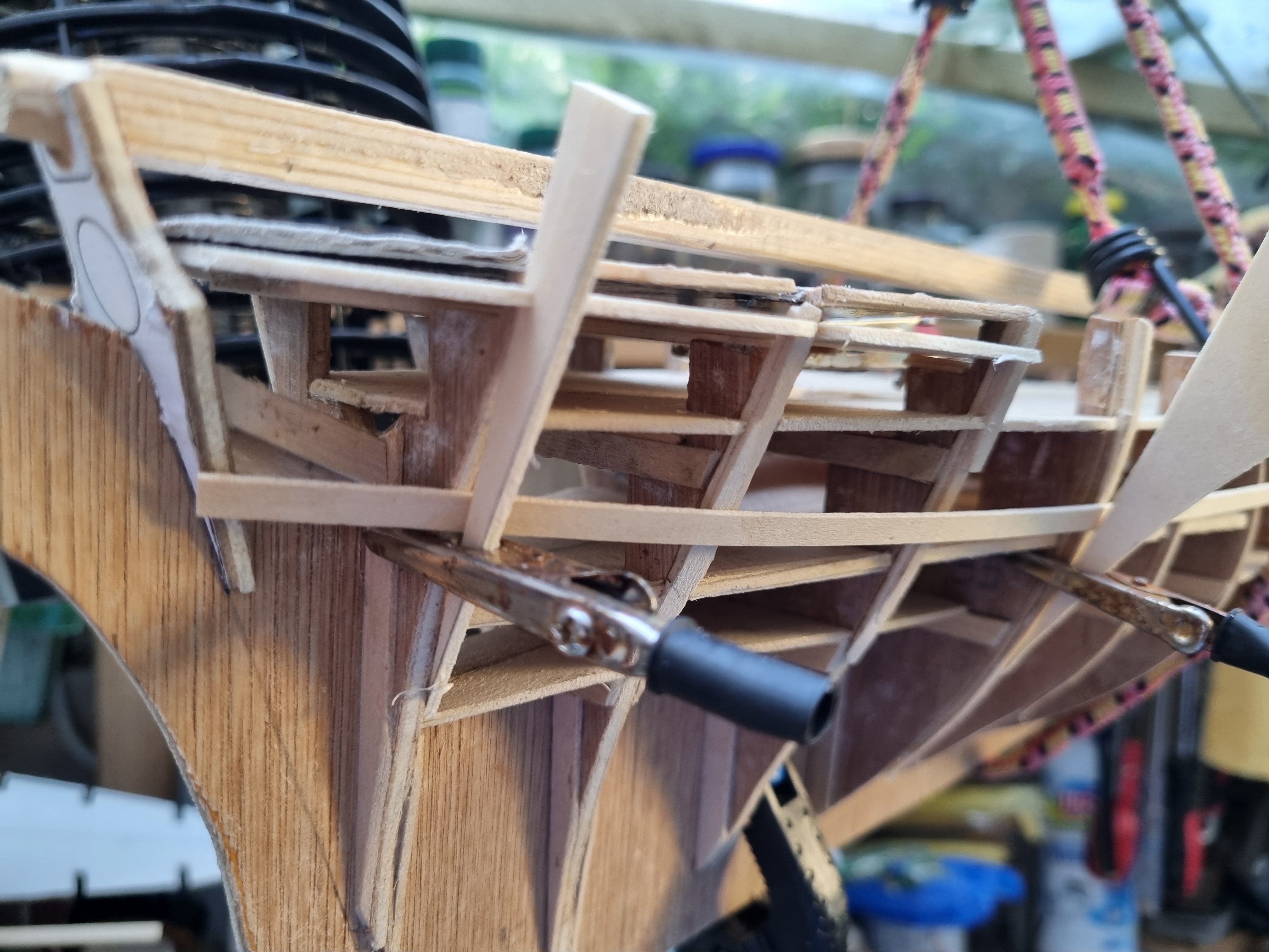
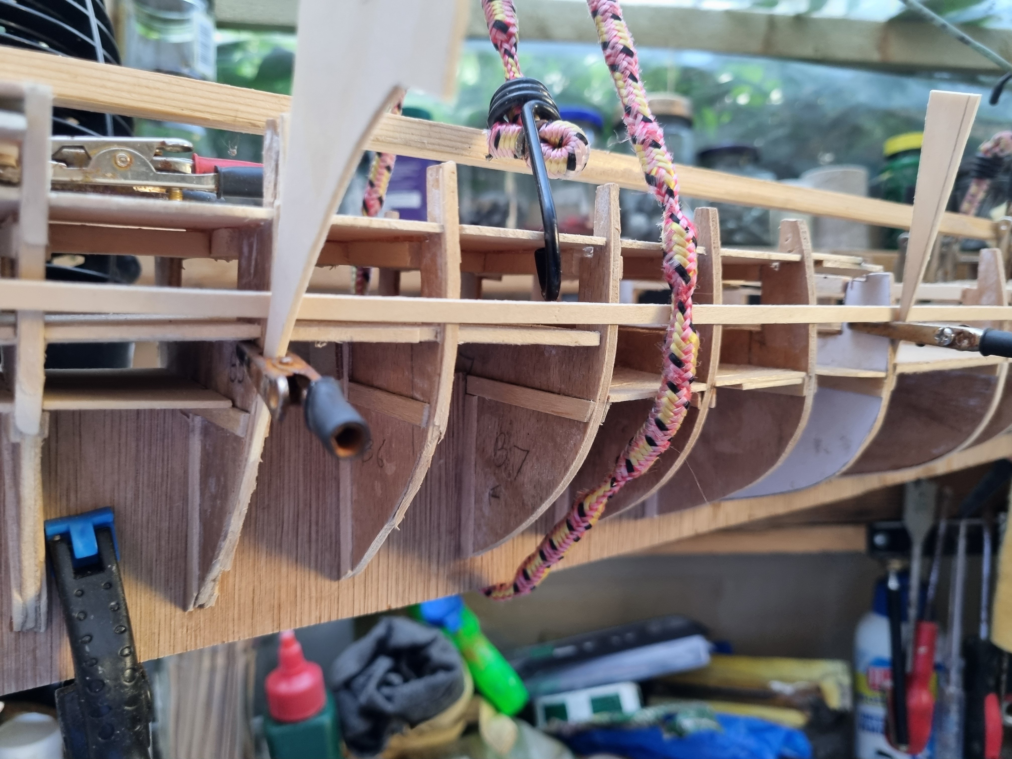
Using a strip of 1/32 bass wood to check the shape. As you can see, B4 needed to be brought in line. Simon


-
My old mum used to do crosswords to keep her brain active. She made it to 90 but the last 3 years were a trial for her, she knew something was up when she couldn't do the Times or Telegraph puzzles anymore. When she finally crossed that final frontier, it was a mercy for her. Did a bit more this evening, glued in the forward section of the main deck and cut out the forcastle deck. Bit more shaping to do as the forecastle is oversize. Simon


-
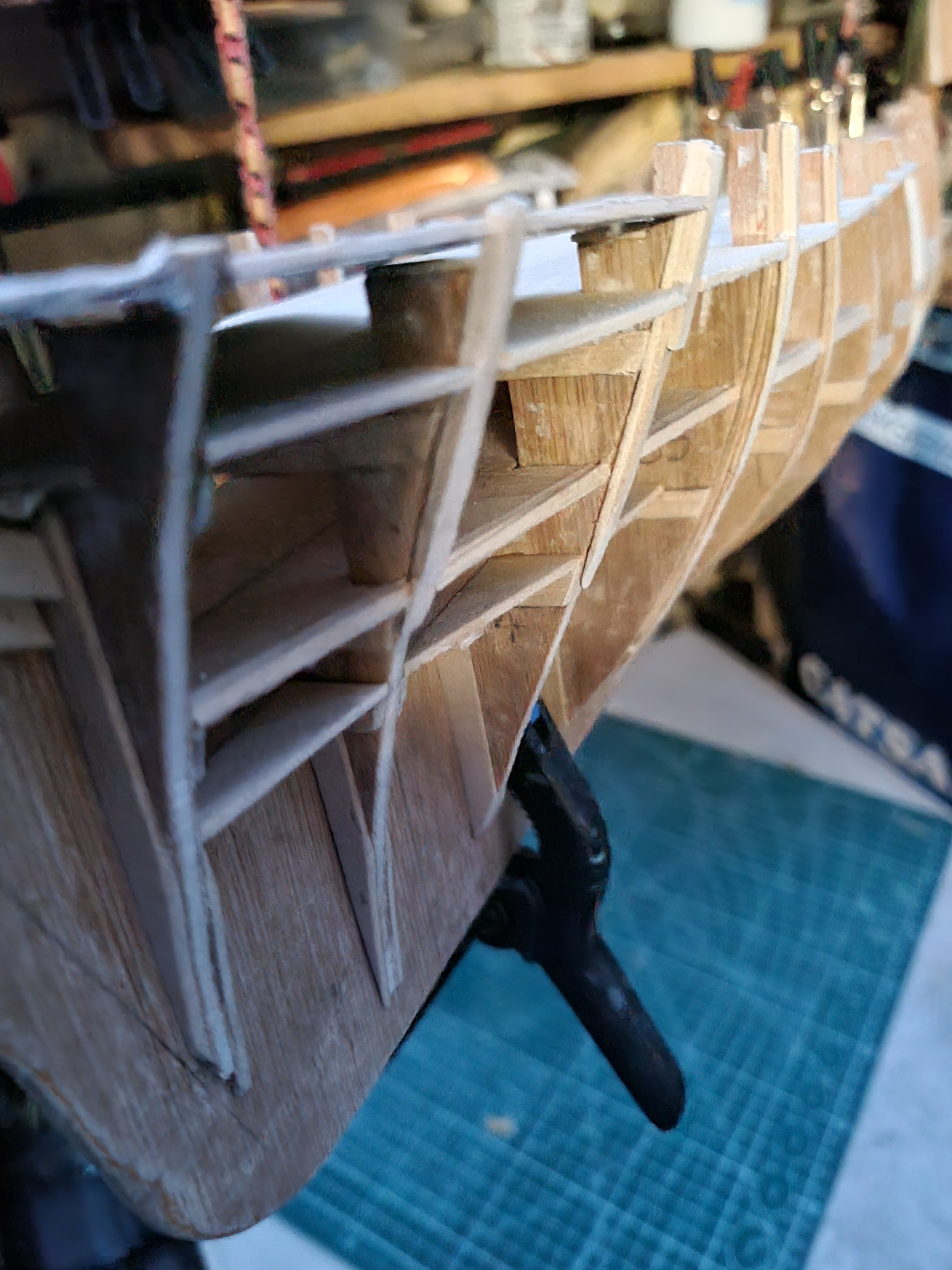
These three bulkheads are the most complex as the curves transfer from convex to concave shapes. I am happy at the deck levels of the shape but lower down, not so much. I am using a very flexible strip of 1/32" bass wood to check on the shape. I am also going back to the original drawings and the cad interpretation to check I am heading in the right direction. Simon
-
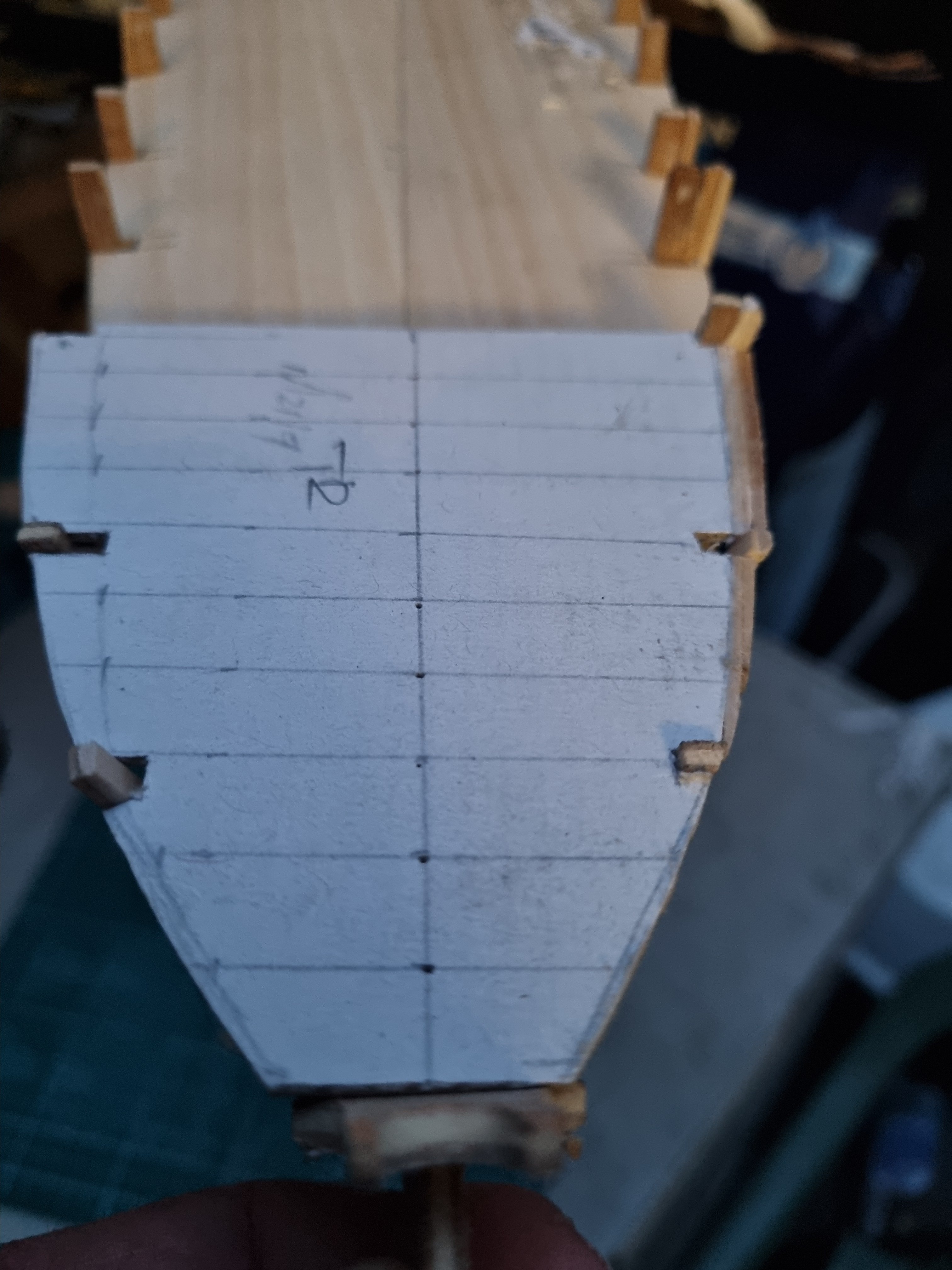
Not my best bit of photography I have taken the template for the fore deck and adjusted the port side by adding strips of wood. I will then use the dimensions for the port to reduce the starboard side to match. This means I had to add to the first couple of frames, still a bit of shaping to do there. Bit to wet outside this evening due to the persistent rain this evening. Simon


-
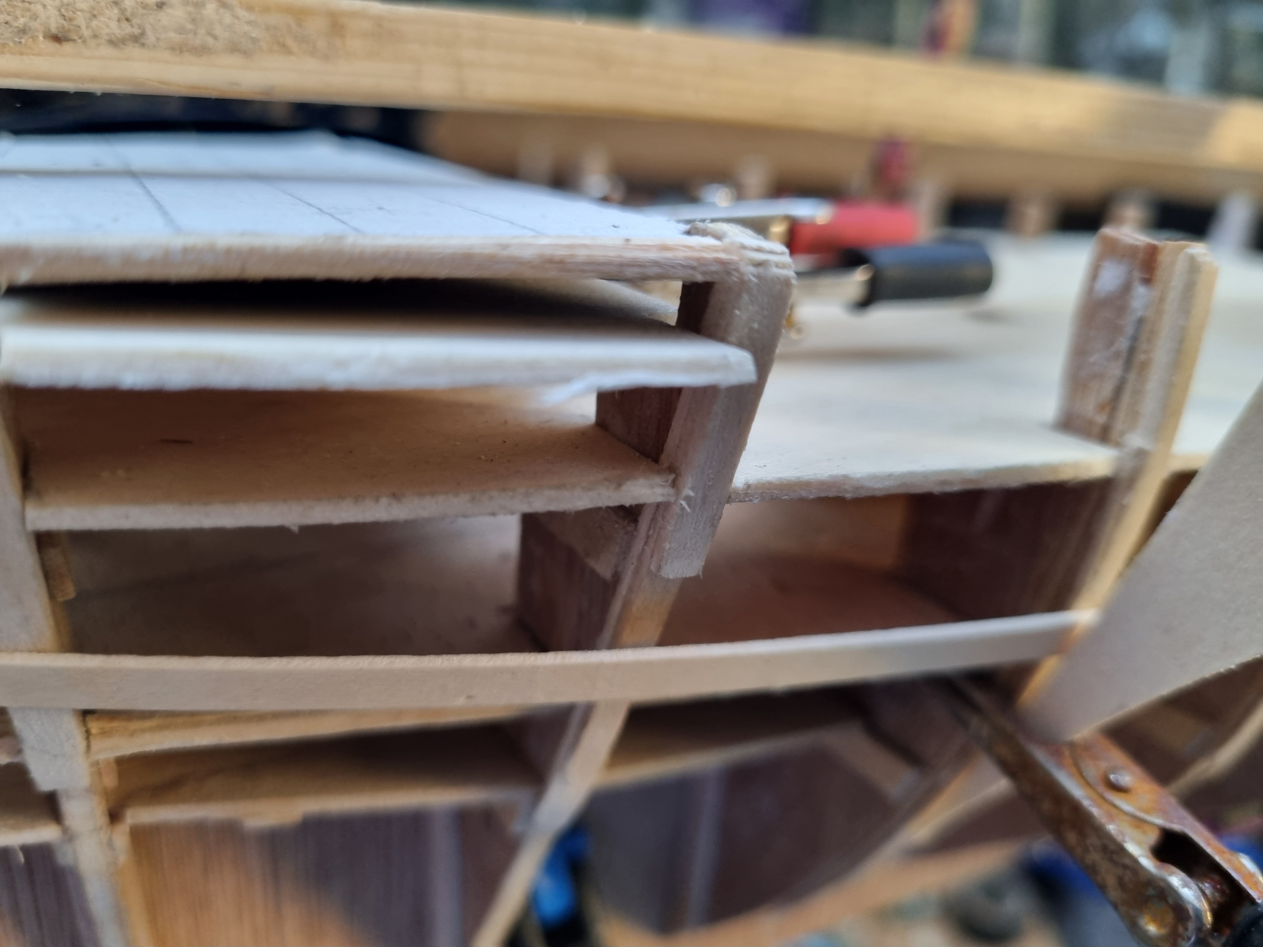
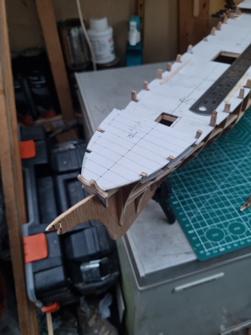
The broken tabs are not proving to be a problem, as you can see, I have managed to create templates for the main, fore and aft decks. I have erred on the side of caution and they are all slightly over sized so I can sand the actual decks once they are cut out. The main deck was made in three parts and after getting them lined up, I have glued strips over the joins. This is shoebox card so it's quite sturdy. Frustratingly, she is not symmetrical, some of which can be rectified by building up or filing down excess but there will be a case of "so be it". I will know it but I doubt any casual observer will. One of those annoying things is the bow, the ply has warped, I am taking steps to correct this but there may still be a slight twist to port in the end. I suspect once the decks are fixed in place and the hull planed, most of this will be sorted. Simon

-
Cutty Sark by NenadM
My Fathers Son replied to NenadM's topic in - Build logs for subjects built 1851 - 1900
Not really, it's just how the sit because of the knot. Work out how they need to present the orientation. The lower deadeye has to have a single hole at the lowest part. So when attaching the line run this around the deadeye and instead of noting the two ends, use a much lighter line to bind the two ends together. Once installed, the lines need to be bound to the mast in the same order as they sit on the platform. It will still not look right until you do the rat lines to pull them in line. I really like your dedication to being fully scratch built including the components. I have to recognise that this is outside my current capabilities and accept that I have to source these for Cutty and Thermopylae. Simon- 4,152 replies
-
- 2
-

-
- cutty sark
- tehnodidakta
- (and 1 more)
-
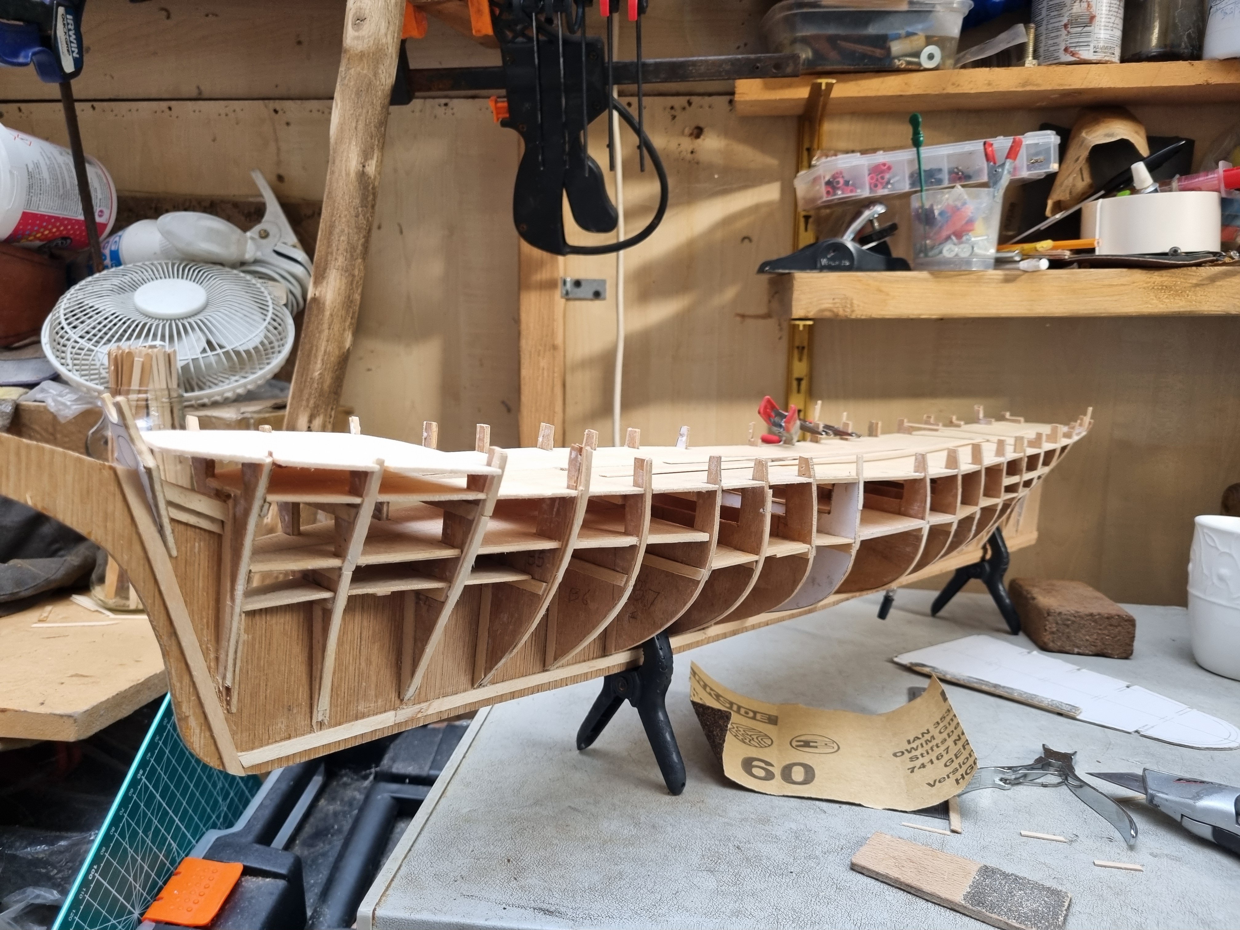
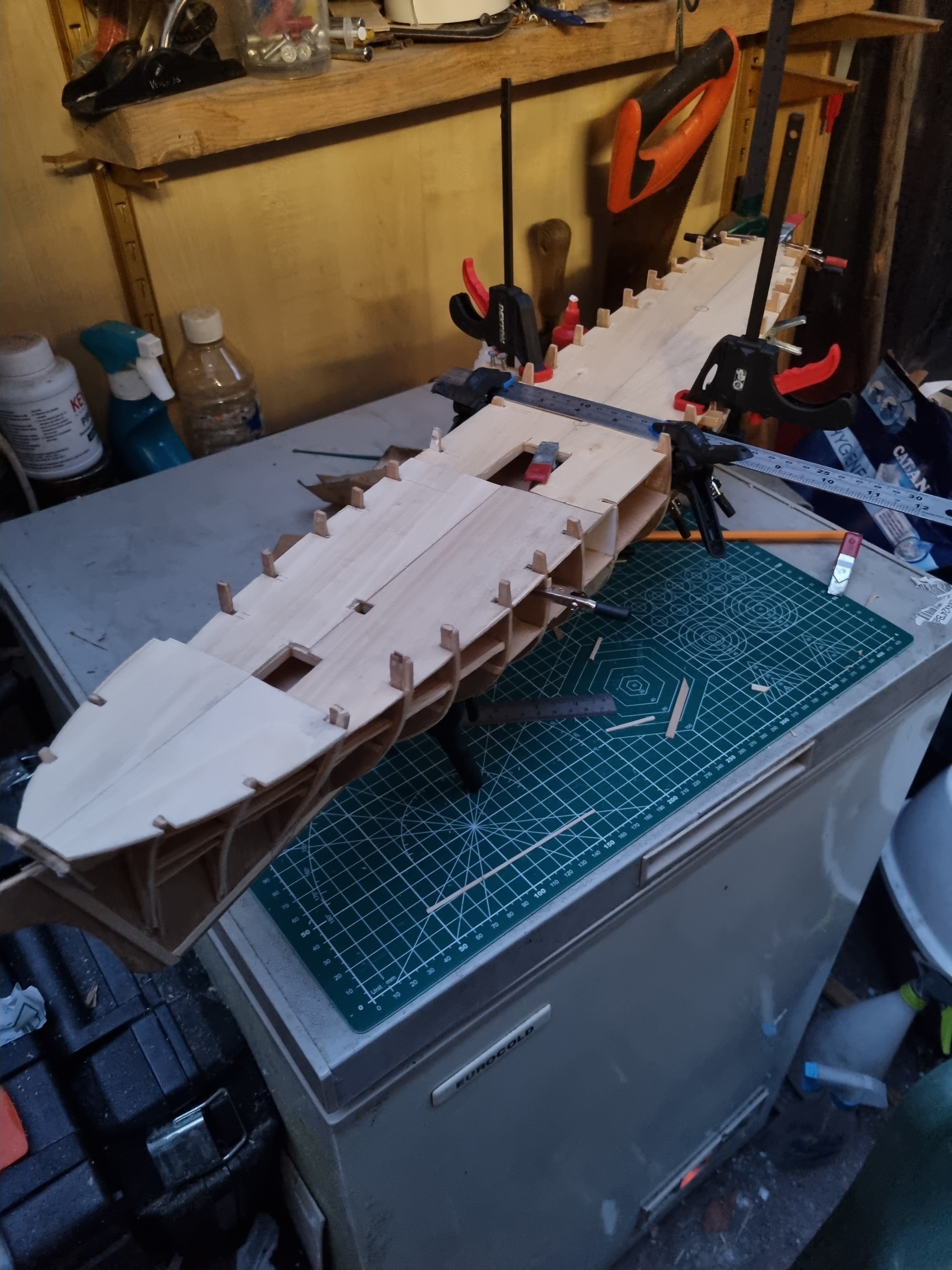
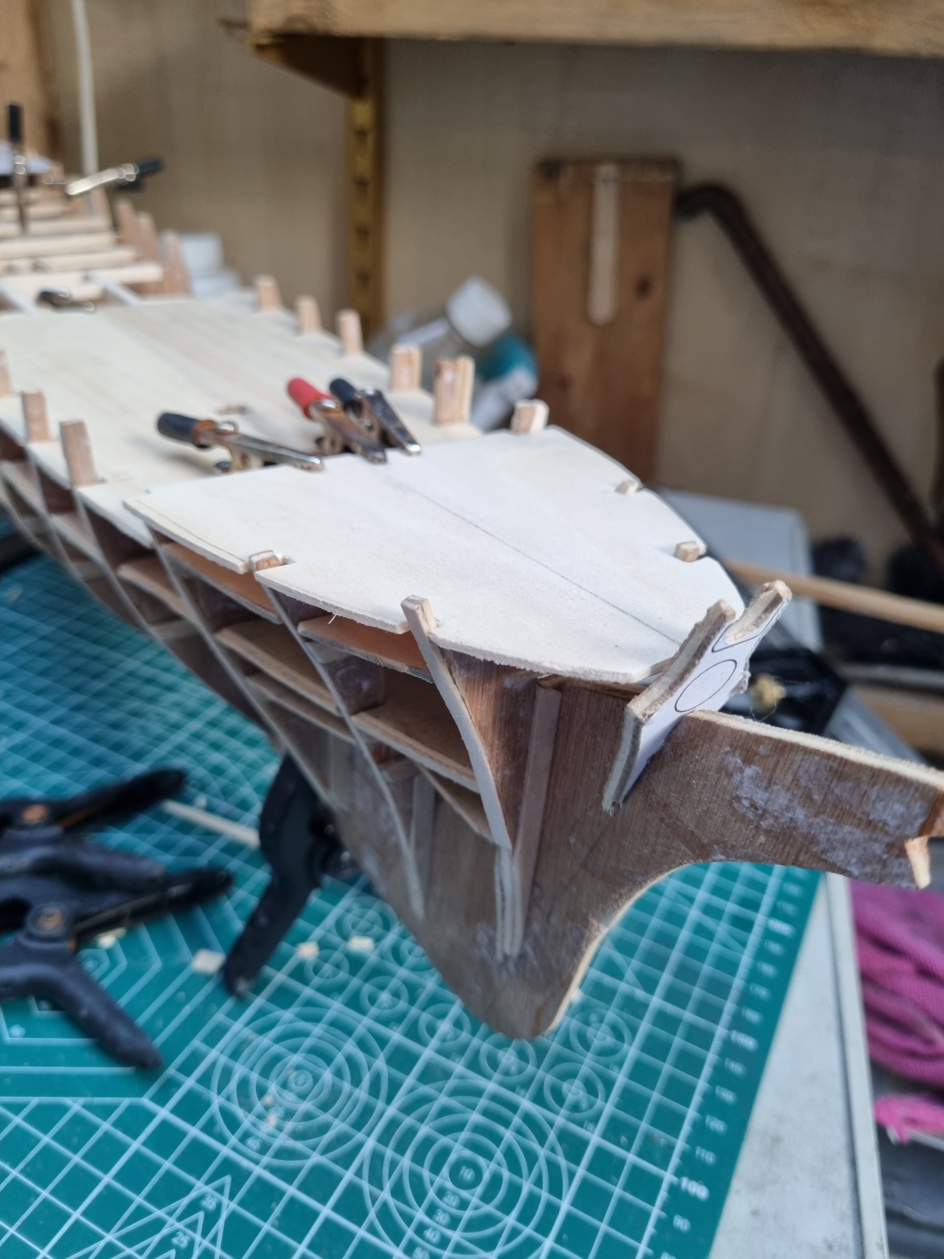
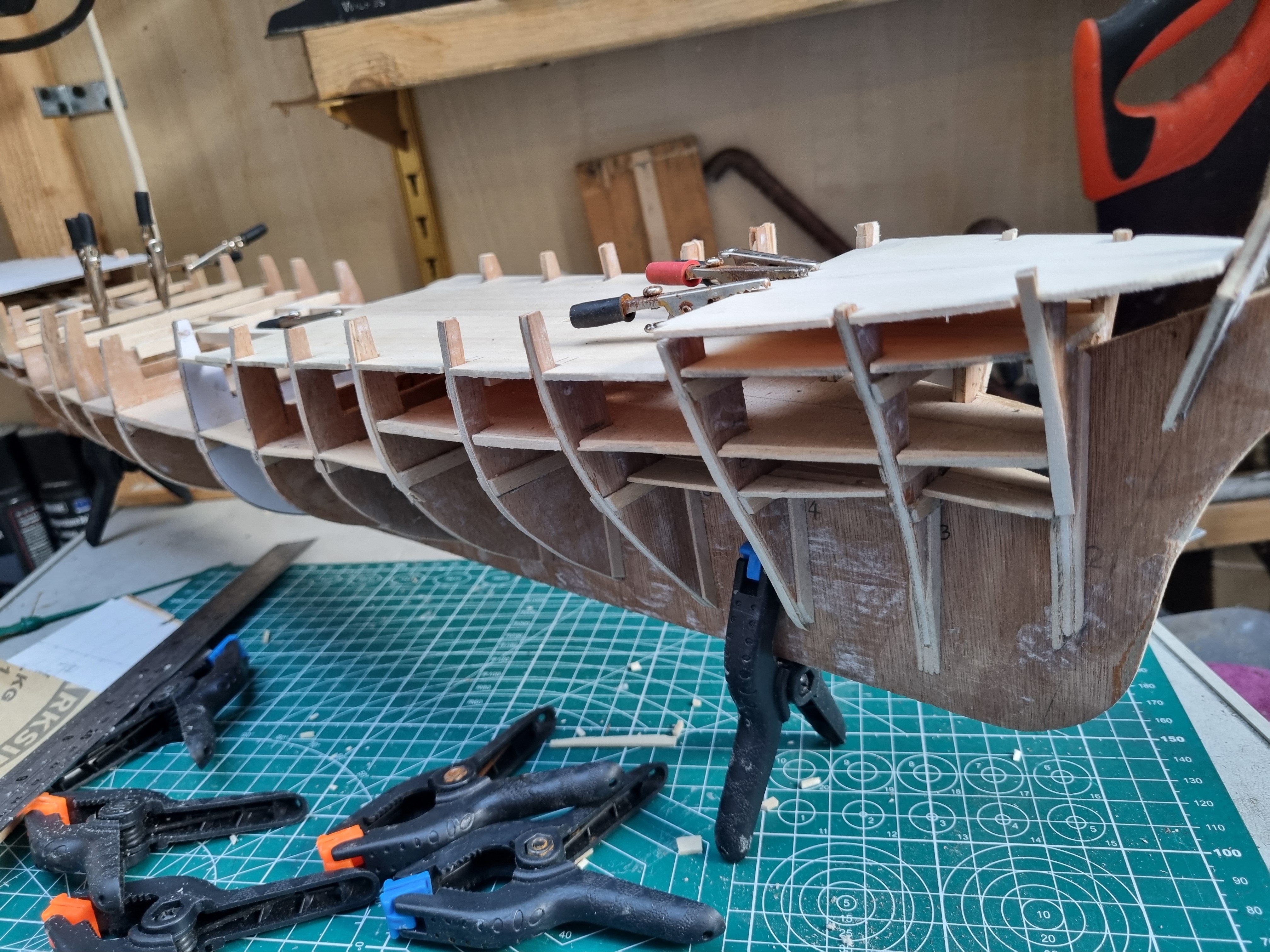
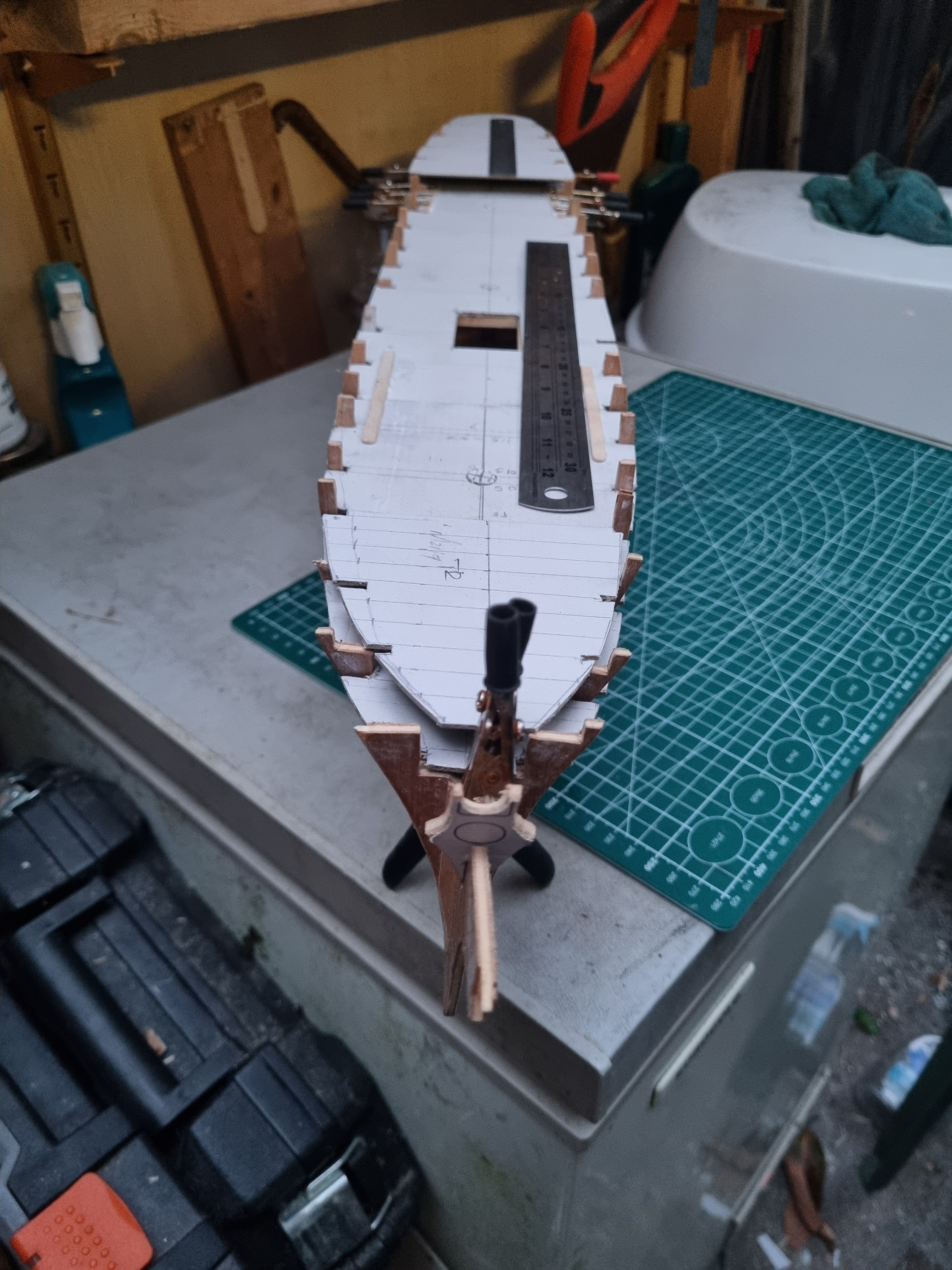
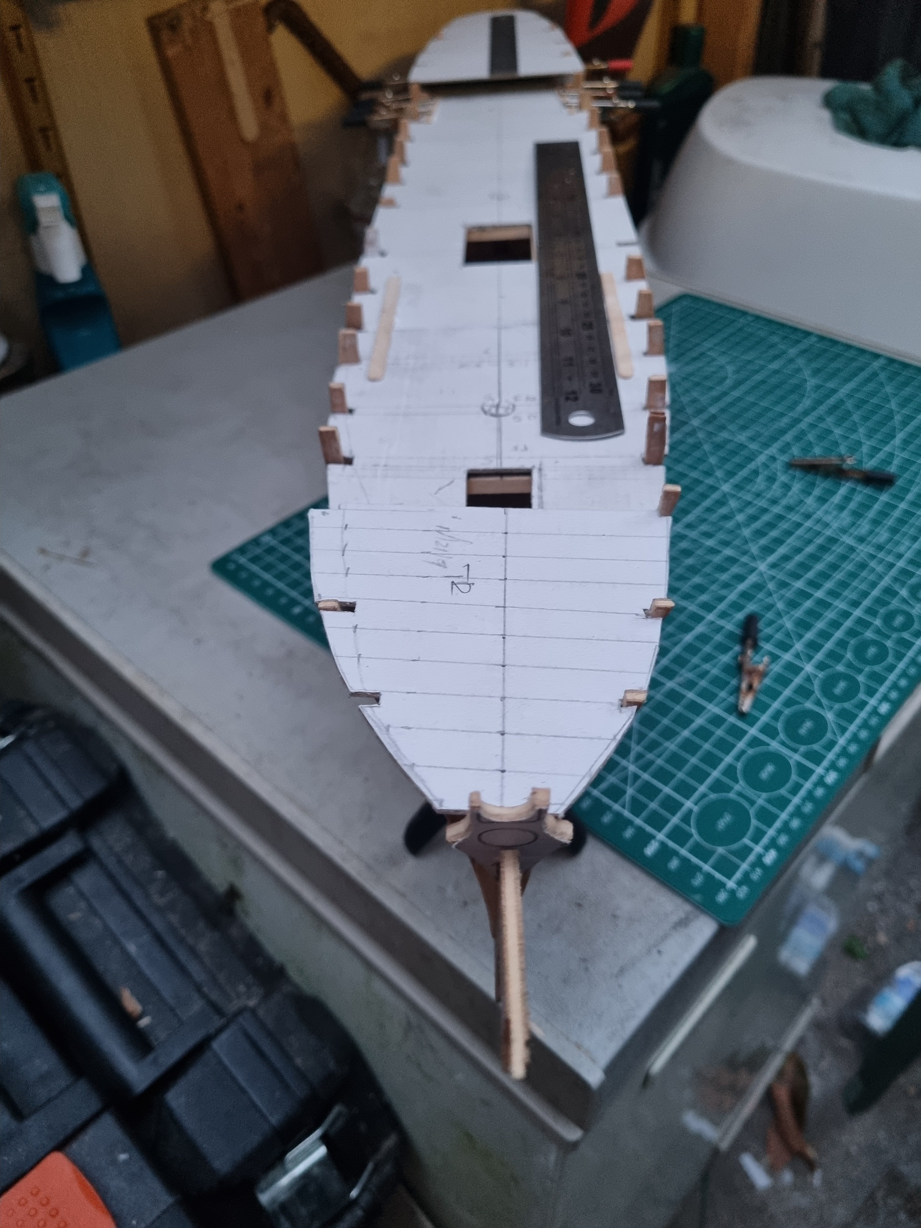
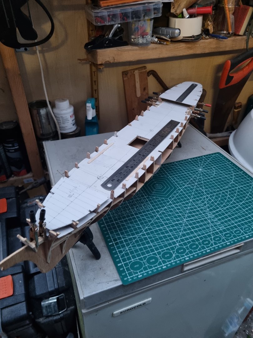
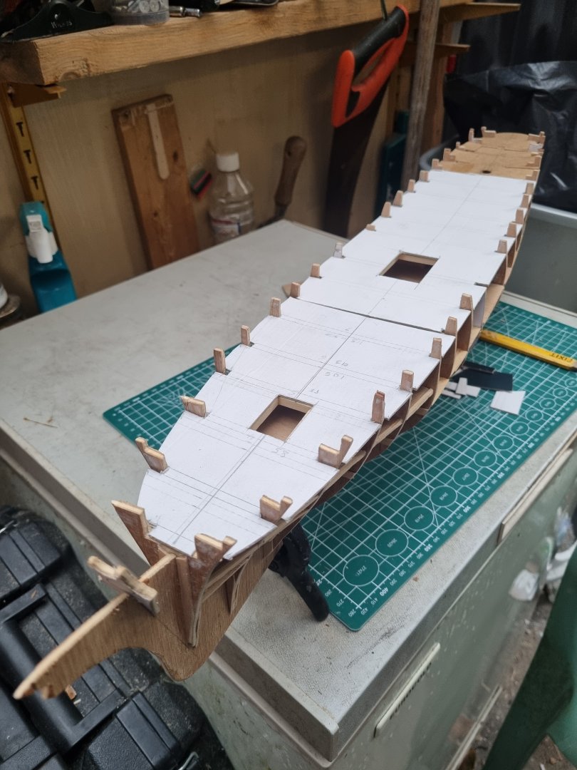
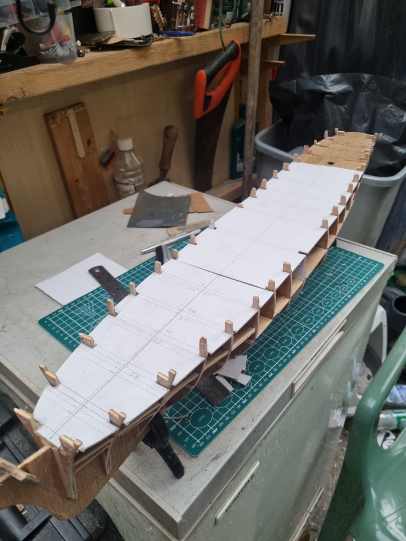
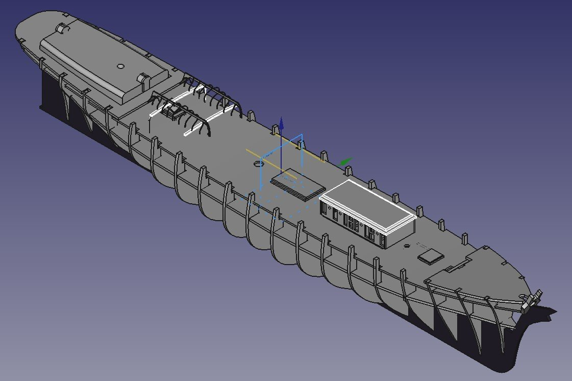
So I have been working on getting the templates set up for the main deck. Having got the general shapes sorted out I can set out the locations of the various items that come through this deck. The mizzen location is sorted for this level. However, the Fore and Main masts are located on the false deck but I now have to calculate the location on the main deck taking into account the degree of rake of each mast. I will clean up the pencil marks on these templates and redraw some guide lines for the final ply deck to eradicate the errors on the templates. The more observant will notice there are a few bits of damage to the tabs on the frames. Two down to my heavy hands and the other two down to my four legged assistants.
-
Had to work today so didn't get round to big T but this is where I got to last night

-
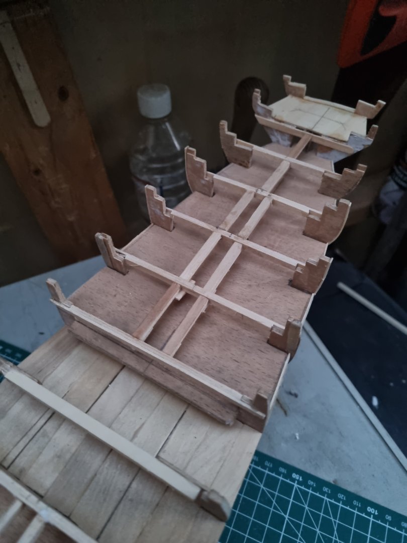
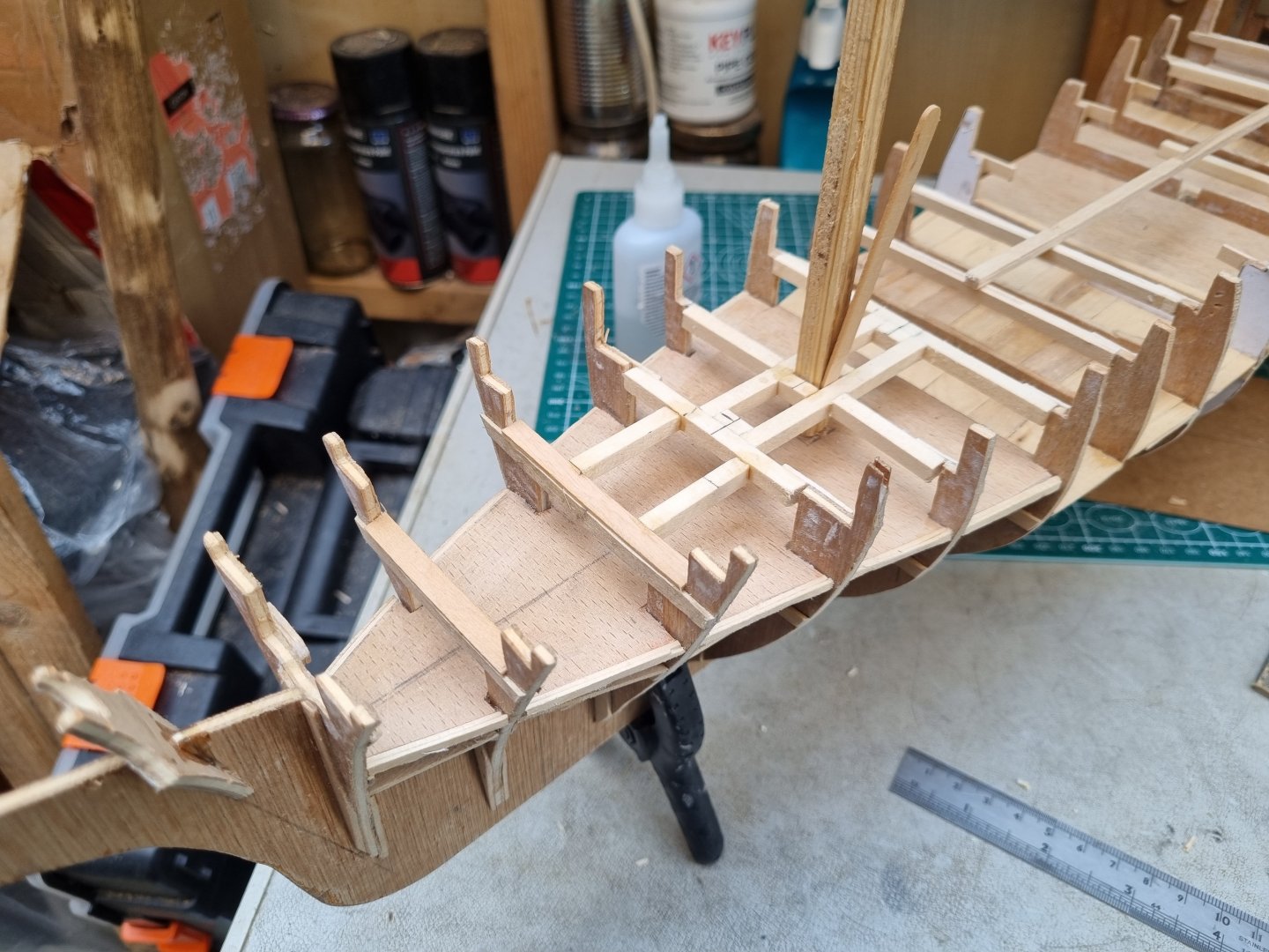
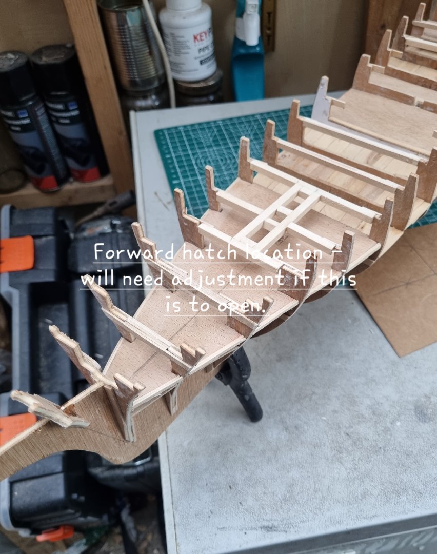
Well, I have roughed out the plan for the forward hatch and it's a bugger. It intersects frame 5 and as 6 is already compromised I am. Louth to do that to 5 as well. A temporary mast is in place so I can be sure it is vertical and has the correct lean aft, set at 86 degrees. Photos as promised. I should be OK with the main hatch as the main mast is immediately aft of frame 11 and I have not set out the beams 10 through 12. Simon
-
Worked on the deck beams again this evening and was under the impression that I had finished the fore section. I was aware that I would have to design a frame for the central hatch but I had forgotten the forward hatch. It looks like it's between frames 5 & 6, in front of the foremast so I should be OK there. On the other hand it looks like the central hatch spans 11 & 12 forward of the main mast. I need to take the dimensions for all these and rough out a cunning plan. Actually getting to construct this is fun but can be quite challenging. I promise photos tomorrow. Simon
-
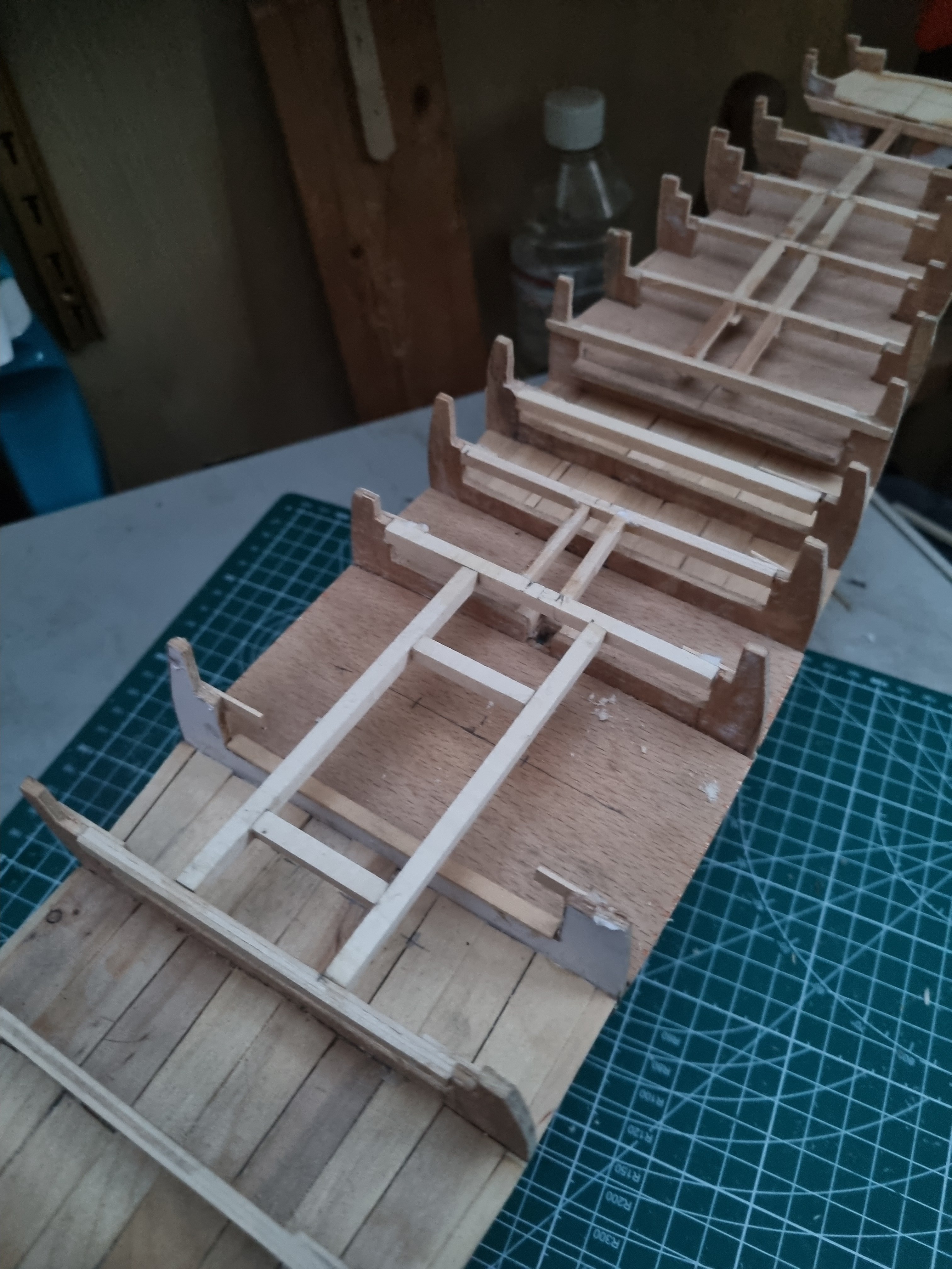
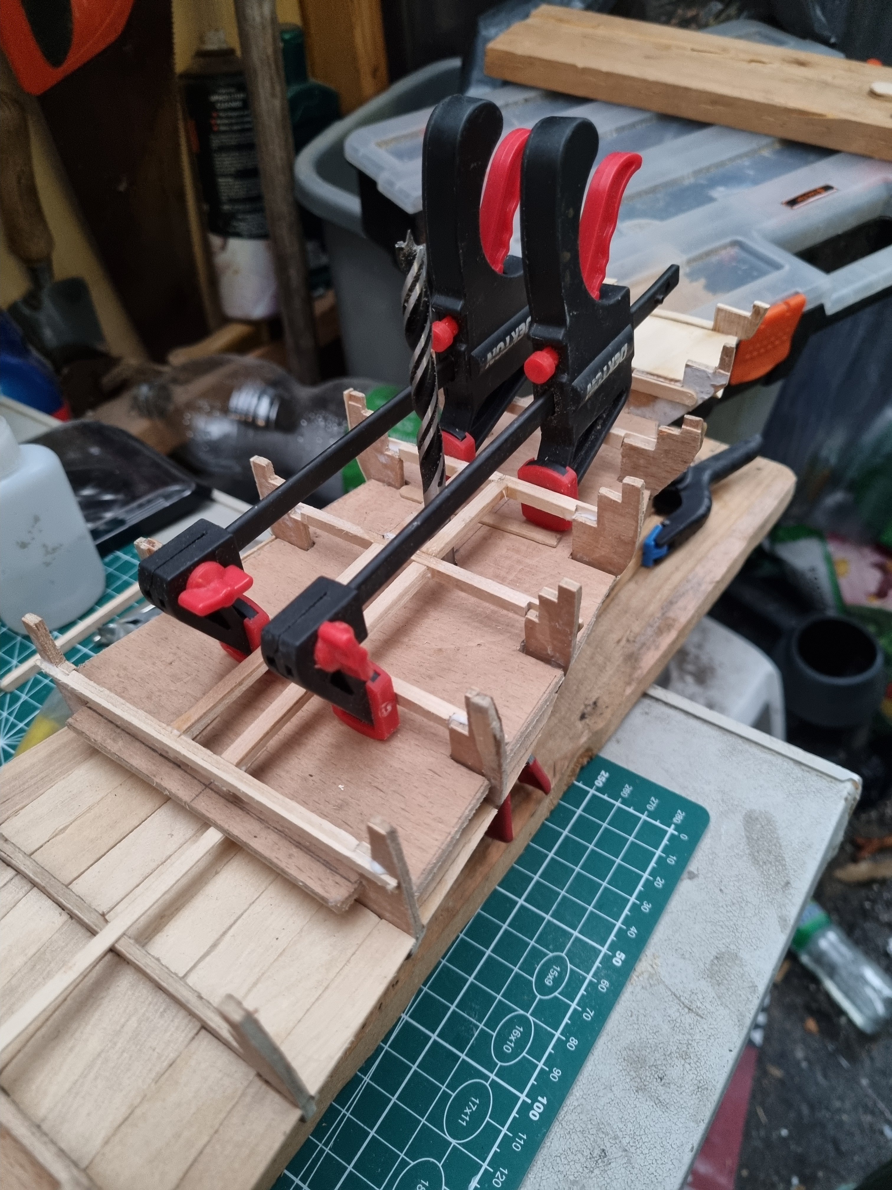
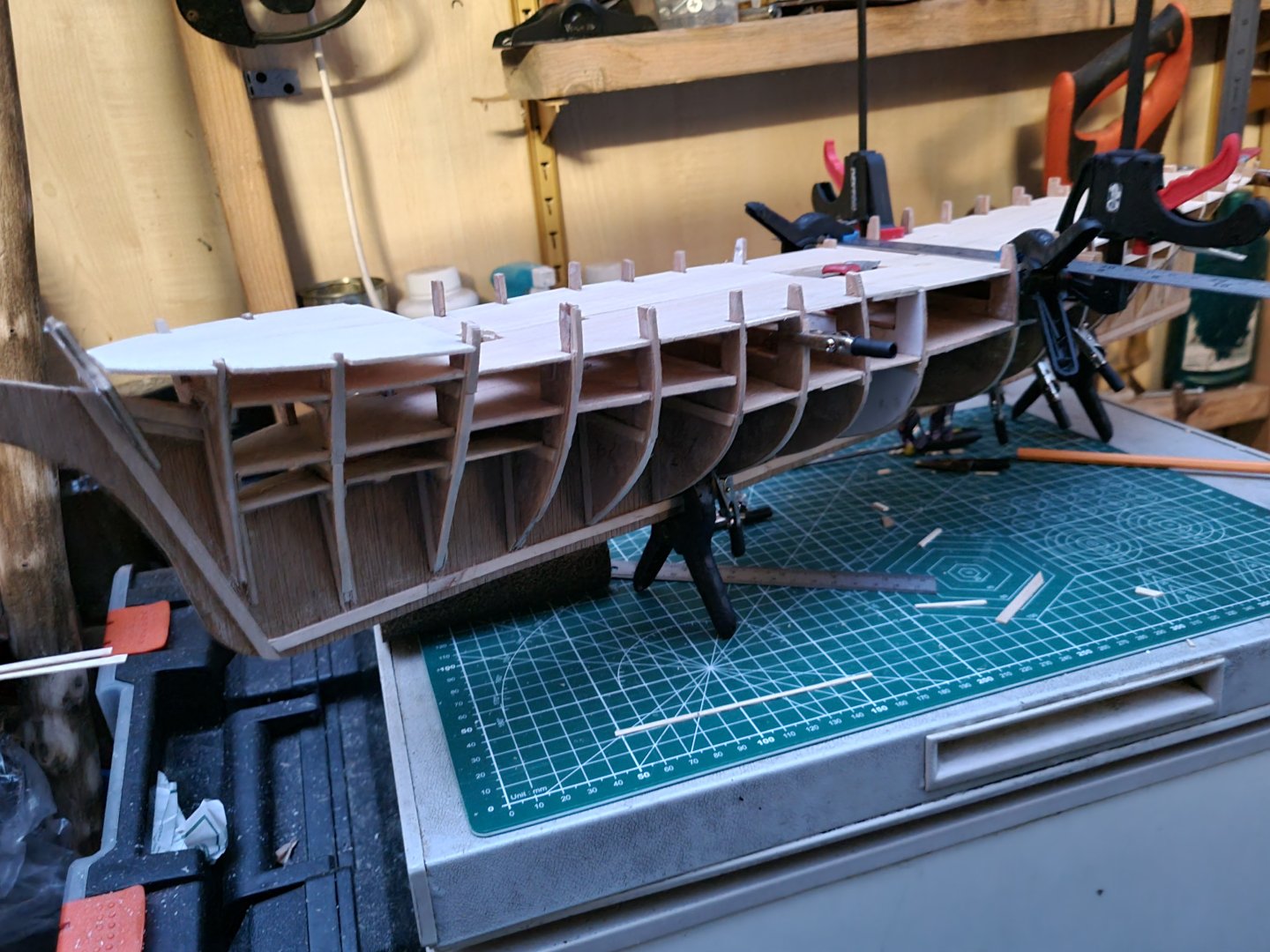
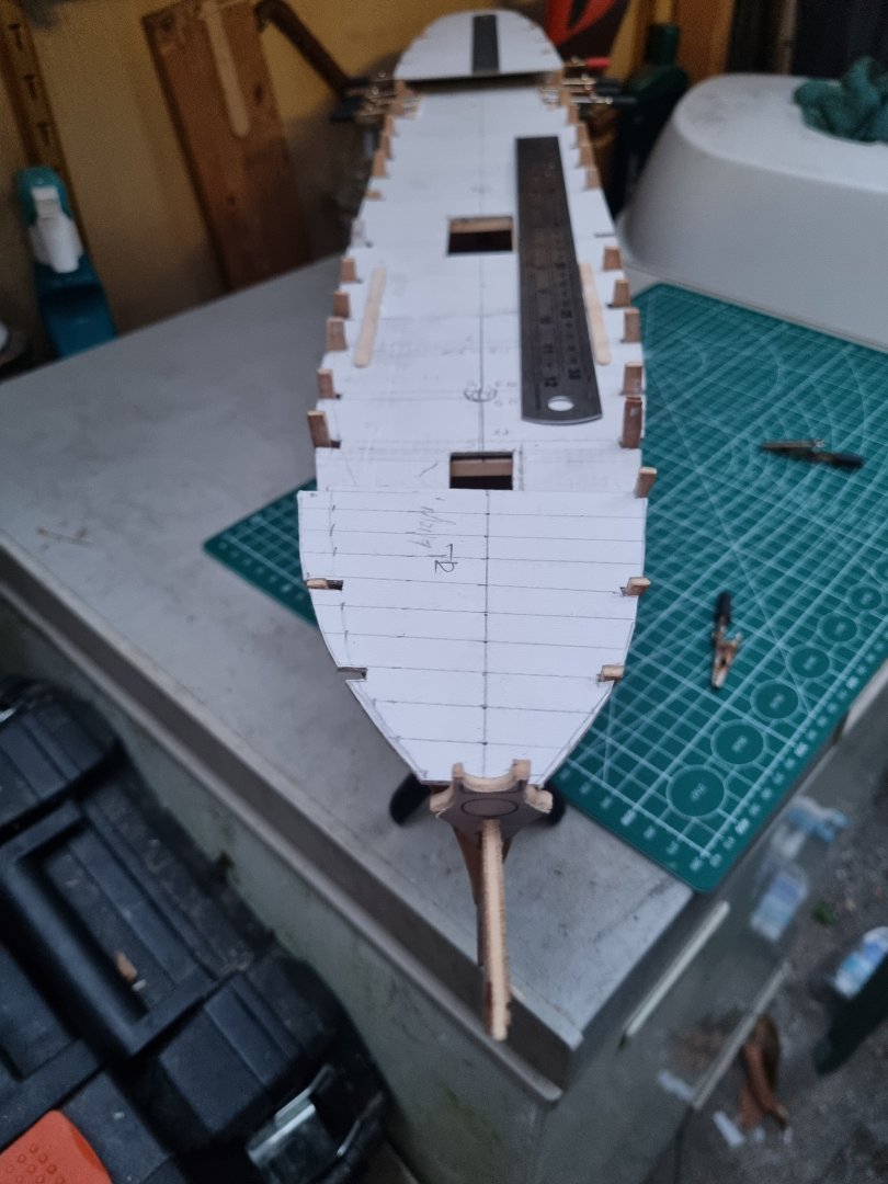
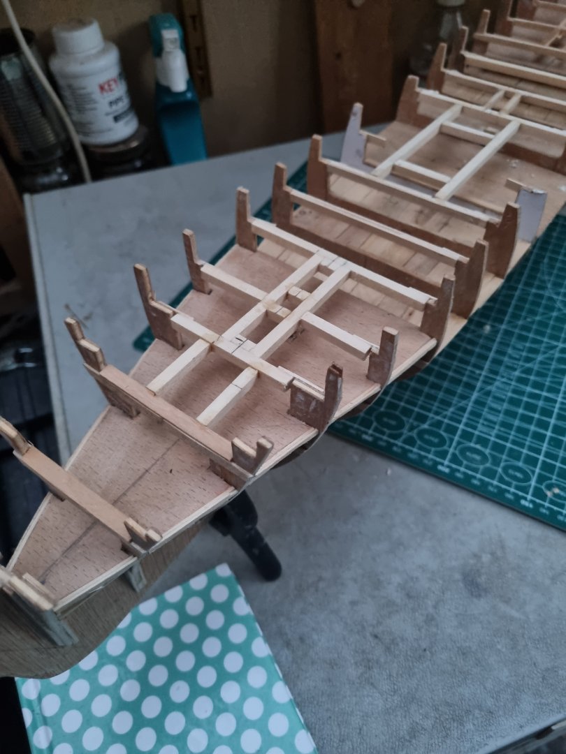
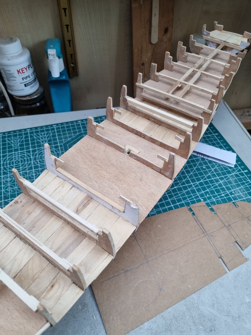
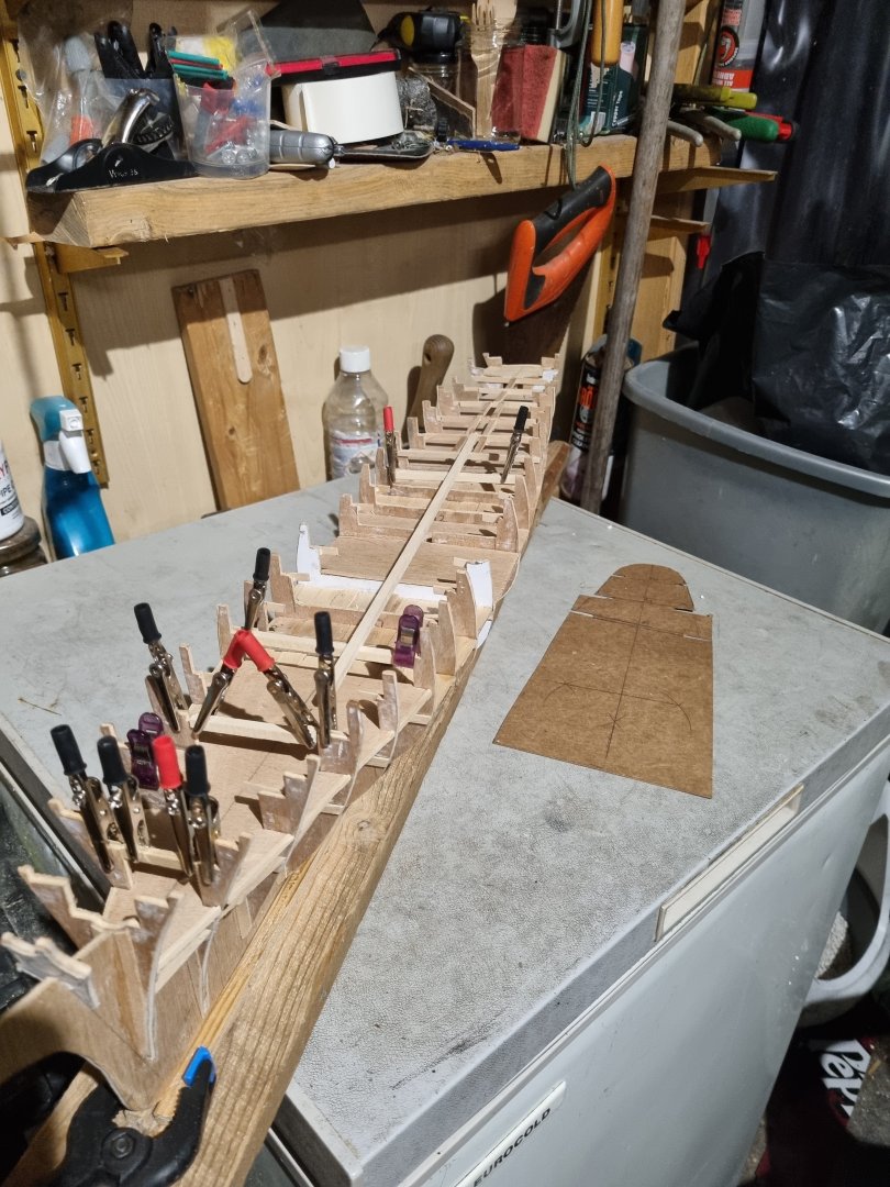
Worked on the cross beams again this evening. They are lining up nicely but I need to work out where the the hatch entrances will be located so I can set up frames for them. All three masts will clash with the cross beams in some way so I will be doing the same thing for them. Cross beams that might be visible through hatches are in new 3/16 square bass wood but the rest will be laminated coffee stirrers. You can see a cardboard stencil I am preparing for the aft section of the main deck. Simon
-
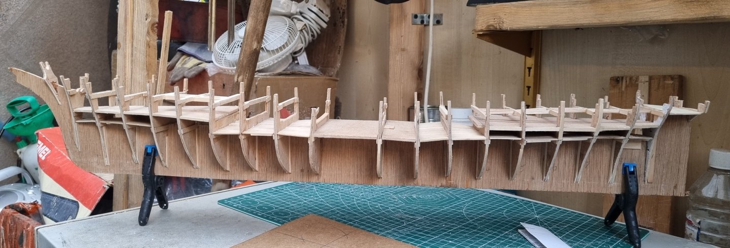
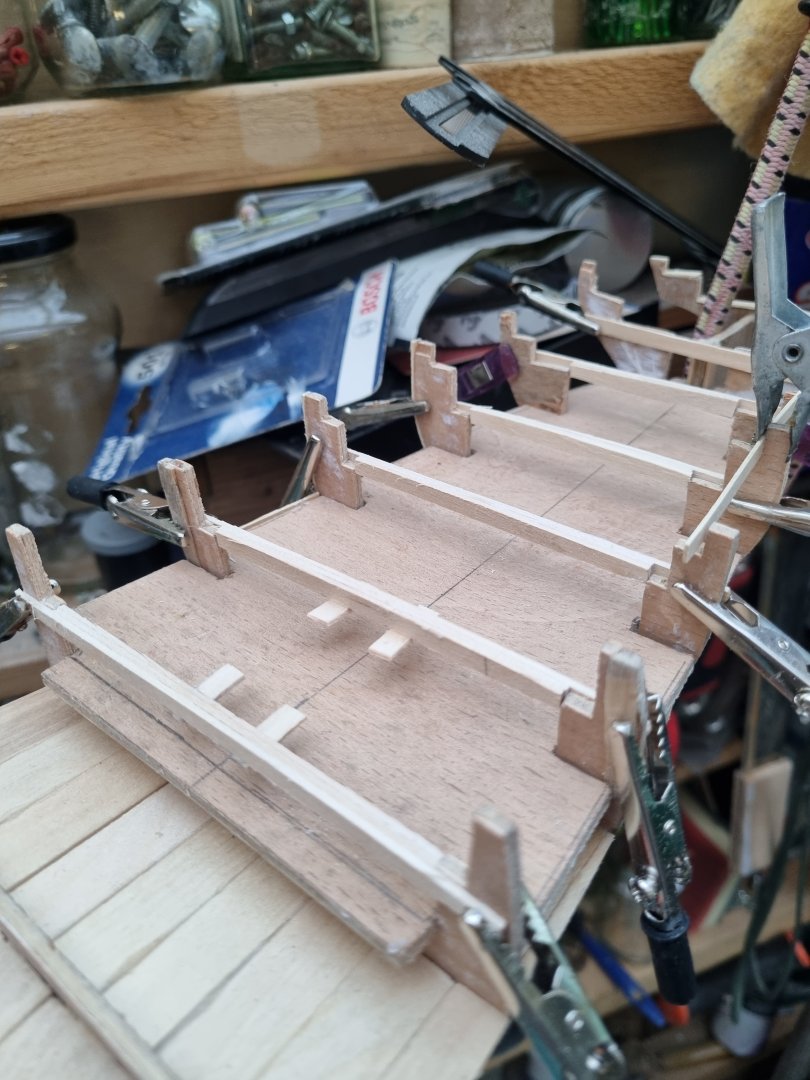
Been a busy day today and haven't found too much time for the boat this weekend. So this is the aft end the dummy deck is locked in and the support cross beams for the main deck are temporary clamped in place. The cross beams are lined up and glued in place. I have drilled through the false deck to the bracing below for the Foremast and the Mizzen. The central supports for 14, 15 and 16 are in place. I will add additional bracing for and aft of the mast. This mast will go through the aft deck and deckhouse. As long as I am careful to be accurate, this mast should finish vertical with a rake aft of 84 degrees. A different angle view, judging by the list to Starboard of the mizzen mast, there is a little adjustment to do. Simon


-
I did think of looking for a second hand kit but I don't intend to spend too much on this boat, hence my use of materials that I get for free. I did have to pay £9 for the sheet of ply and I spent £10 on some Bass wood today but that's it so far. I do have some set aside for decent strip wood from Cornwall model boats but at 27p to the dearer woods at 37p per strip it should not cost more than another £12 to plank the hull. I hope you create a log for your build, I will tag along when you do. Simon