HOLIDAY DONATION DRIVE - SUPPORT MSW - DO YOUR PART TO KEEP THIS GREAT FORUM GOING! (Only 13 donations so far - C'mon guys!)
×


Capella
-
Posts
138 -
Joined
-
Last visited
Content Type
Profiles
Forums
Gallery
Events
Everything posted by Capella
-
 Thanks, @Dziadeczek the pvc tube method sounds intriguing. And I'll look for that video.
 -
Recommended pins for planking?
Capella replied to Capella's topic in Modeling tools and Workshop Equipment
@Oldsalt1950 what are my options regarding clamps? Thanks! -
I just finished my first kit and during that build, one of the struggles that I had was to keep the water warm while soaking planks. I use a plank bender: the standard version with the block of wood with two different curved sections and an electric heater with a 1 inch roller. I read here that soaking the wood in warm - vice cold - water will make it more pliable, as this will loosen up the fibers better. And I can confirm that based on my experiences with the aforementioned first build, I found that, even after soaking the planks for a good 15 minutes in cold water, and then using the bender, the planks didn't bend as easily, but if I filled up a small 12" x 6" tub with hot water from the sink and then soaked planks in that, they were much easier to bend however I needed them to. My question, really is, does anyone know of a tub of some sort that can hold long planks and keep the water warm - instead of refilling a tub of water with hot water for every other plank that I need to bend? Or maybe some sort of home-made contraption for that purpose?
-
I'd appreciate it if you guys could offer suggestions on methods of pinning planks to bulkheads to hold while the glue dries. I'd imagine they'd have to be very thin pins - not the "bulletin board" pins from the office - so they don't split the planks or make ghastly-large holes. Also, when planking the second layer, is pinning recommended - especially if the hull will not be painted? Thanks!
-
@RossRGood to know! I grew up in Maplewood. Small world!
-
Initial disclaimer: I just ordered the kit yesterday. For now, I thought I'd introduce myself, talk about my first build in terms of my experience with my first kit, about what I'm looking forward to for this second build. My first build was the US Ranger by Corel (no build log). I actually bought it about 12 years ago, started it, got the deck planked and the first hull layer done. I then shelved it - mainly out of frustration - until COVID happened. Good time to get back into it! Unfortunately, for someone's first wood model ship experience, it was a hot mess: poorly translated and confusing instructions. inaccurate drawings, some of the pre-cut parts were cut in the wrong position. Case in point: the forward mast hole in the deck was too far back. Not realizing it at the time, I mounted the mast and when I got to placing the main sail, it was squeezed between the mast and the rigging. The blocks were just bad and I ended up buying my own. I also ran out of some planking, so I had to purchase that. There were a lot of steps that were logically out of order - especially for the rigging, forcing me to work around a lot of rigging that could/should have been done later. But, through all of that, I learned a LOT. To go over EVERY step before getting started, make sure every part is there and is cut/manufactured right, do a lot of dry-mounting before gluing; plus I learned a lot of helpful tricks and strategies along the way. Fortunately, I had you guys to help me get through the challenges, and in the end, I'm proud of what I accomplished! Looking for my second build, I wanted something equally challenging (but not challenging in terms of the poor quality of the kit itself), but made by a MUCH better company and with lots of resources to utilize. After hours of research I decided on the HMS Beagle purchased from OcCre and in my initial build log research I found NINE build logs, so I have a lot of resources to use from others' experiences with the same ship. While I'm waiting for the kit to arrive (can anyone speak to how long OcCre's orders typically take to arrive? I live in Central MN, US.), I'm going to research the build logs available and maybe pop in a question here. Looking forward to the kit arriving and getting started!
-
Just ordered this very same ship from Occre about an hour ago. I'll be watching your log VERY closely. 😉 By the way , how long did it take to arrive after you ordered it?
-
@Bob CleekaMakes perfect sense. Thanks!
-
Thanks so much for providing that link. In all of my searching for lathe information - including here on MSW, I don't know how I missed it. I particularly like the idea of a "second" or "middle" tailstock, as while I was test-sanding dowels during the construction of mine, I was coming to the realization of the issues that will arise when sanding longer dowels.
-
Could you provide in more detail what you're describing? Particularly the "for long parts" comments. While testing my lathe with a 20" (or so) dowel, I came to realize that sanding the middl of such a long dowel would be difficult at best. It sounds like you're addressing such a problem, but I'm just not able to picture what you're describing.
-
@Jaager Thanks for the explanation. I'm only just finishing my first wood model ship, so I'm still learning the jargon and terminology of the hobby. Maybe this lathe project gave the impression that I have some experience in wood model ship building, and/or mechanical or electrical experience - which couldn't be further from the truth! I simply saw a need: I had much difficulty tapering the various masts and spars for my ship (having used the method of chucking the dowel in a handheld drill and sanding it with a towel between the sandpaper and my hand). I broke - and purchased - too many dowels to make what I needed for my project, and then came up with the idea that I originally posted at the beginning of this thread. I appreciate you taking the time to address my qquestion!
-
Okay, if that works with your budget, great! Not to be snarky, but I said in my original post - the very title of this thread, in fact - was that I was on a budget. Considering the fact that I spent a mere $58 on the entire project, $225 is a lot to me - especially since I accomplished the same outcome.
-
I'm interested in the information you provided, but there are some terms and points that I'm not familiar with, or have different experiences with: I understand that the dowels may curve - that's been my experience with the ones that I've purchased from Walmart and Menard's. But, "Froe"? "Dog leg spars"? Do you mean spars that are angled in some way? What type of application would that entail? I just built this for tapering wood model ship masts, spars, etc. My Irwin clamps have been sufficient in clamping things for keeping them secure while working on them, and for securing two pieces that I glued together. I'd be interested in some clarification. Thanks!
-
I definitely don't have the engineering or electrical experience or ingenuity to do something like that, but hey, if that's a "better" route to take for the goal, then if you can do it, go for it!
-
I got it from Amazon, like every part listed, except for the pillow block. Each of those items in the list is linked to where I purchased it. And I definitely didn't want a cordless drill for this particular project, as I needed the ability to control the speed, and wanted a foot switch, neither of which you could do (well, **I** could do) with a cordless drill. But yeah, things like drills (and most everything we buy now) are NOT going to last 30 years!
-
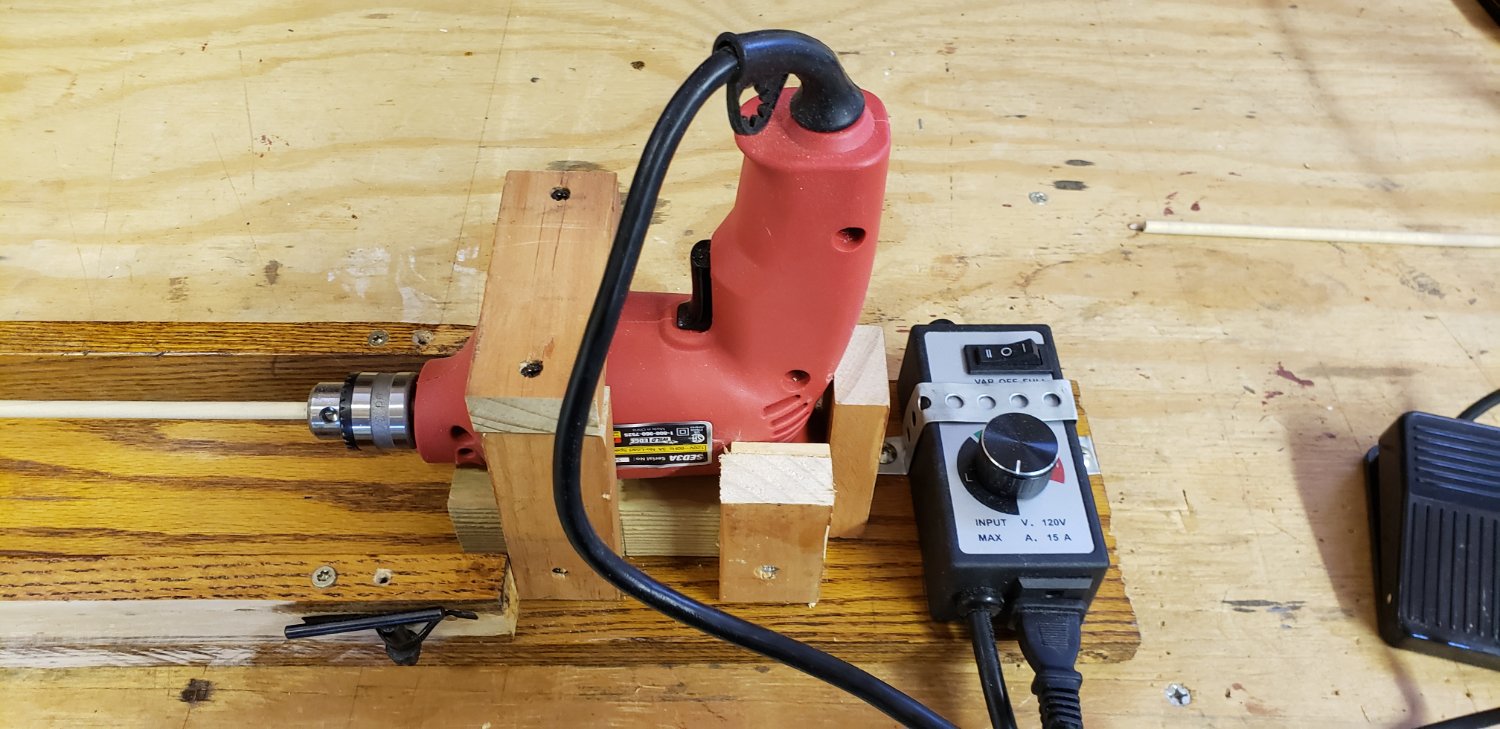
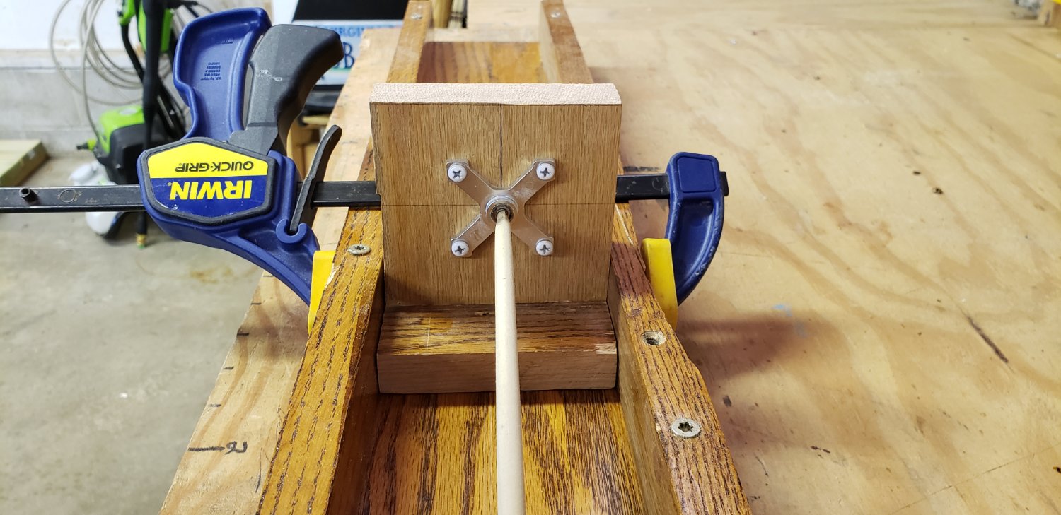
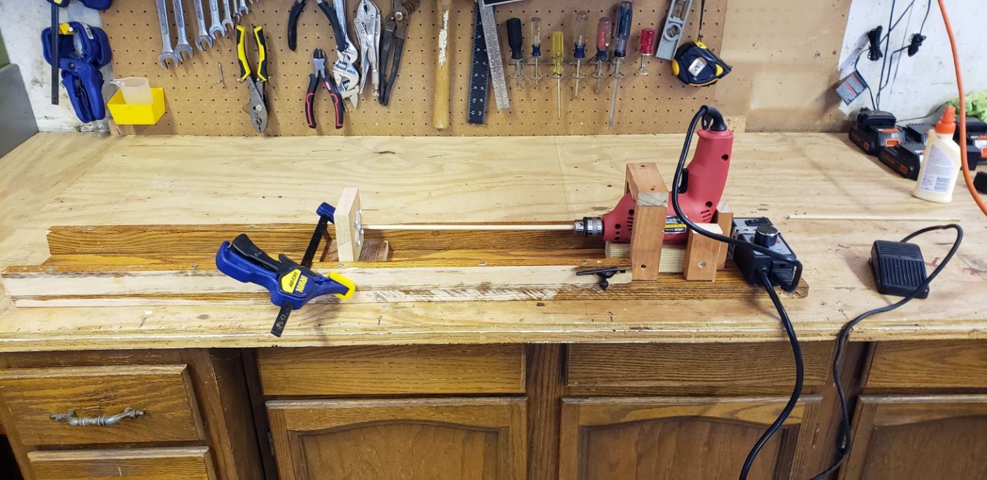
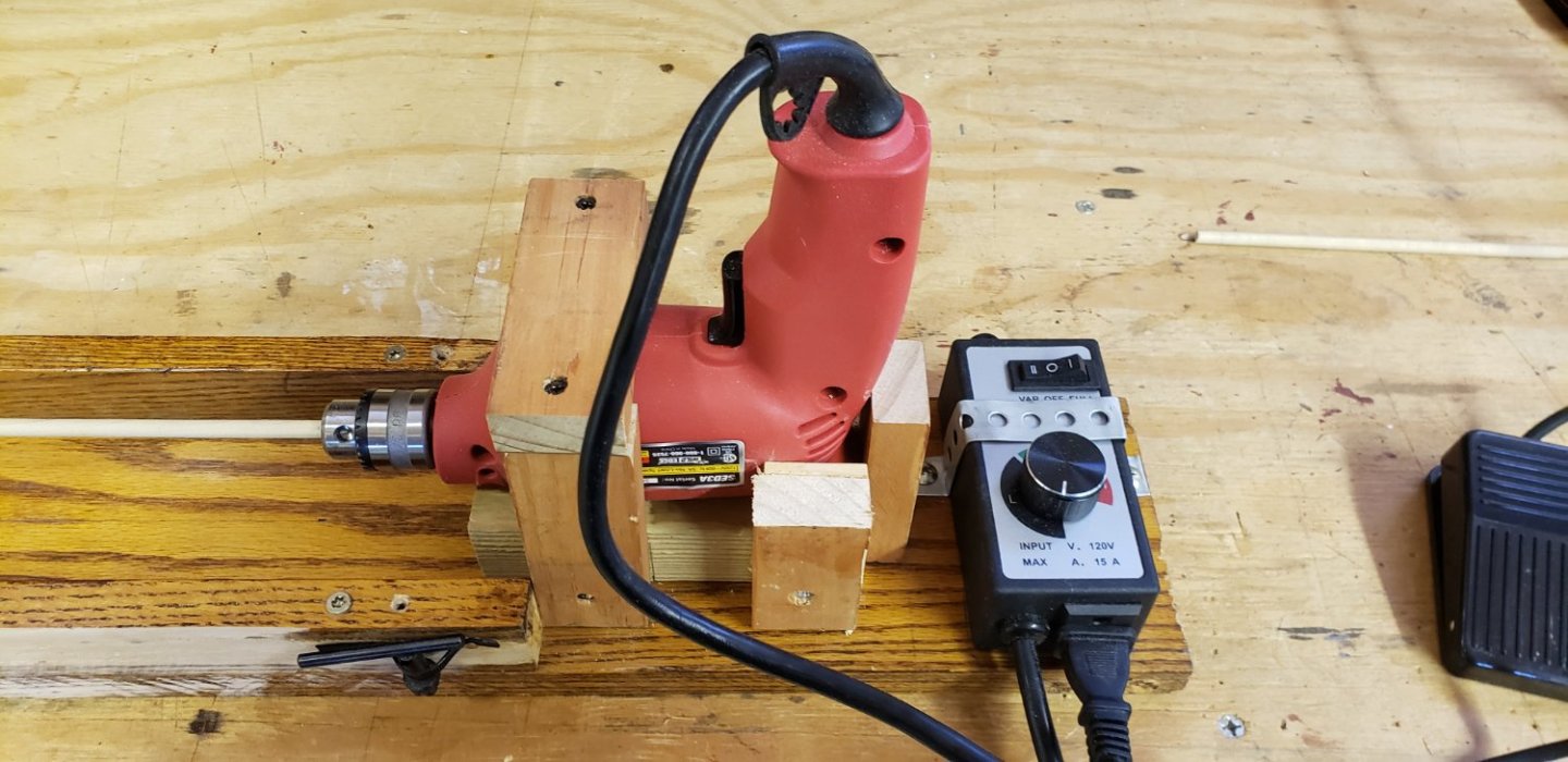
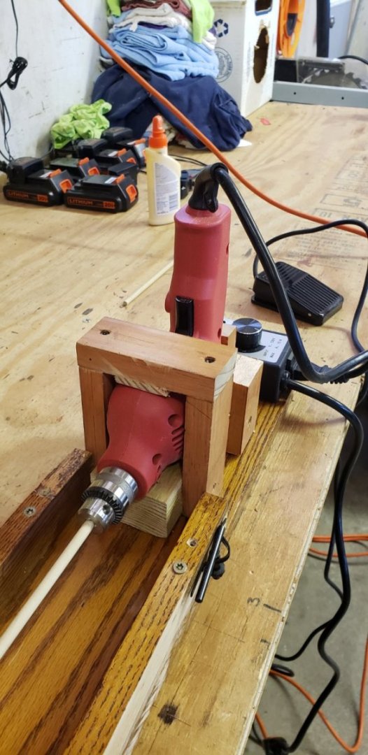
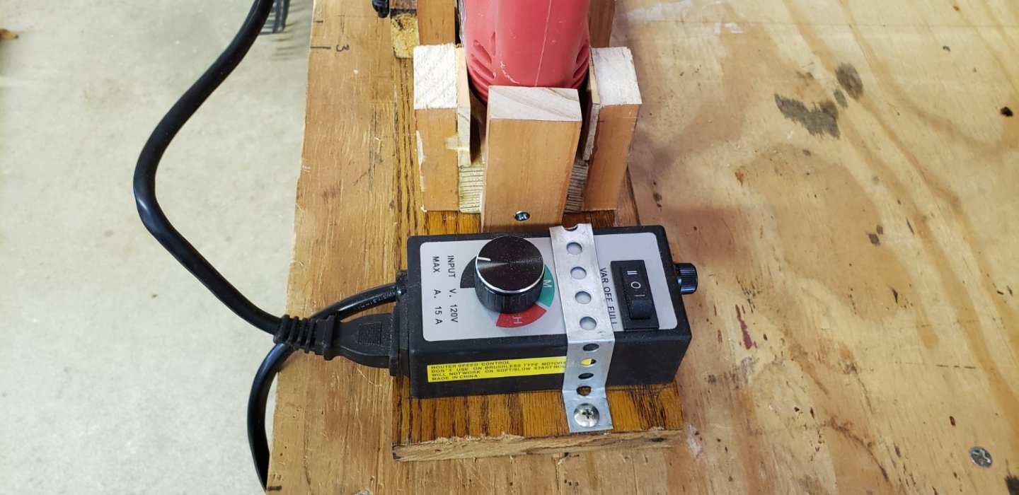
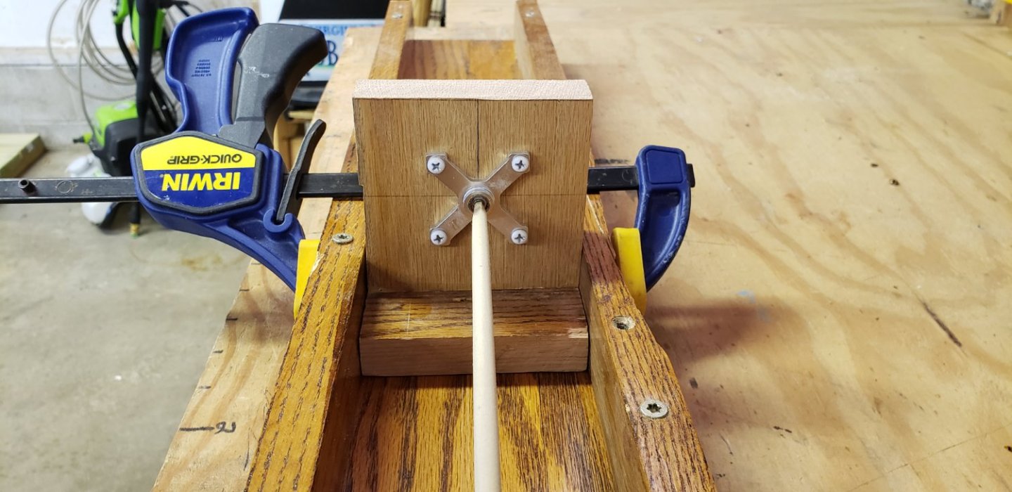
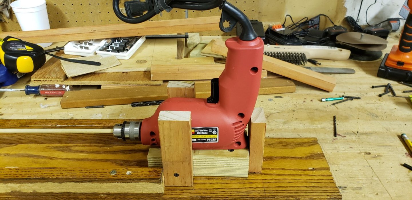
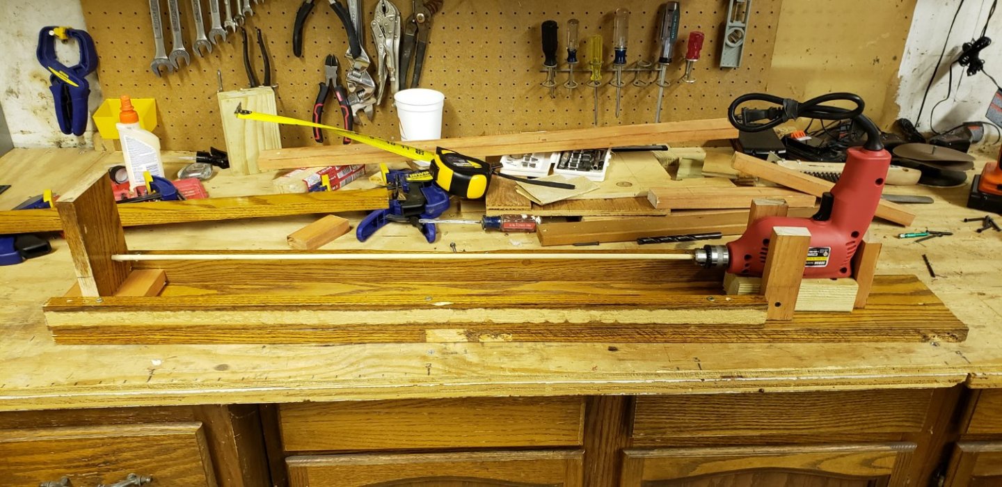
The Finished Product. Behold: "FrankenLathe" By the way, that's the cleanest my garage workbench has been in a looooong time! I'm sure many of you can relate. I wanted to build this as cheaply as possible, but without compromising safety and the effectiveness of its purpose: sanding dowels of various lengths and thicknesses for wood model ships. With a LOT of great advice provided in this thread, I purchased the following items, as I felt their particular "roles" in the operation of the lathe were too important. Links for where I purchased each part are provided in the part name. Prices are in USD as of early November '22. Cheap, corded hand drill with locking trigger: $19 Variable Speed Motor Controller: $22 Momentary Foot Switch: $10 3mm bore Pillow Block: $7 Total purchase: $58 USD The rest was just wood I had laying around. Base length: 42" Base width: 5" Rail length: 32 1/2" Rail height: 1 1/2" Max dowel length (including what's in the drill chuck): 29" The base: The base was as-is: a 42" x 5" length of finished oak that was from a built-in bookcase that was in the house when we bought it. I'm questioning if I needed to make the overall length that long, but I figured I may do taller ships in the future. The masts on my current - and first - project are only 10". I can always move the tailstock close to the headstock for smaller projects. If the base were too short, it's be a lot harder to make it longer! The rails were the same length as the base, and I cut those to stop before the drill mount/headstock assembly. The headstock assembly: The drill is set on a piece of 2x4 that I narrowed to be just the width of the drill at its widest, as I knew that I would need vertical wood supports on the side of the drill to keep it in place. As you can see from the pictures, I used a lot of shims to keep the drill steady in all directions while being used. The stained blocks of wood that you see are from lengths of pine 1x2 cut to various sizes depending on what I needed it for. I glued and screwed all connection points, except for the shims - I just glued those. I ended up redoing each of the parts of the frame structure several times to get each part just right so the dowel stayed centered in the tailstock and the drill did not move while I was sanding. I measured and test-sanded a LOT to get the headstock to stay steady to my satisfaction. The tailstock assembly: The Pillow Block (I had no idea such a thing existed), suggested by @RichardG (Thanks, Richard!) was perfect. The center bore is only 3mm, and I'm wondering if that might cause issues for larger size dowels in the future, but it serves the purpose of my current project and my next planned ship. There are, of course Pillow Blocks with different size bores, so an option in the future might be to get a couple of various sizes and just build more tailstocks and switch them out as needed. That's about it. I started with a basic, rough idea of what I wanted to accomplish - as you can see in the image in my first post, I got great advice here, and I'm very happy with the outcome. I like the name "FrankenLathe" (courtesy of Mrs Capella), as the whole thing is just a mish-mash of purchased items and different pieces of wood and hardware that I had laying around. Oh! I also want to give shout-outs to @Dr PR @Jaager and @wefalck for their suggestions about momentary foot switches and variable speed motor controllers. Really, everyone here had great advice. If you have any questions about some particular point regarding the lathe, I'll be happy to answer them!
-
Another concern that I just thought of: for my current ship project (my first ever, actually) I had two spars (not sure if that's the correct terminology) that had to be tapered at both ends. I really struggled with those and ended up going through several dowels until I didn't damage an already finished end. I ended up using a small piece of cloth and wrapped electrical tape around it. That protected the finished end, but it was pretty wobbly in the drill chuck. Of course, at the time I was holding the drill in my hand, so maybe with everything mounted on the lathe, it'll be more stable even with the cloth/tape method of protecting a finished end.
-
Whether brushless or not, I couldn't say, but it was only $18, so going by your assumption, I'd guess it's not. The motor is 3 Amps.
-
I think that would be a great solution. Thanks, Richard!
-
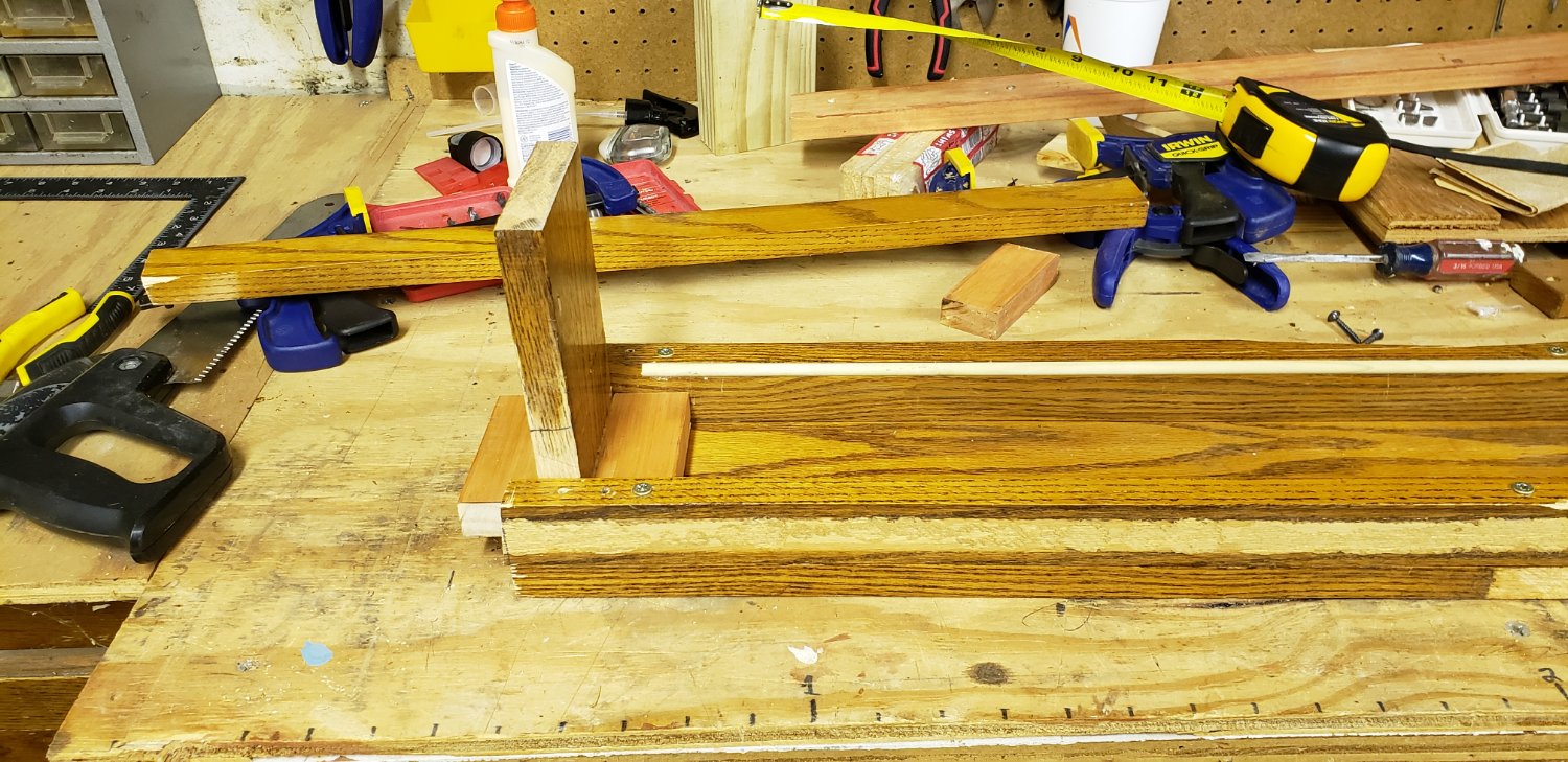
My progress today: I've attached pictures for reference. I had a good 5 hours to work on the lathe today. The house we live in had a large custom-built finished oak, built-in cabinet/bookcase in the living room when we bought it. It didn't fit with our furniture and decor so I tore it down and fortunately had the foresight to keep all of the wood, which proved to be good material for the lathe base and guide rails for the sliding tailstock. I've been using anything from my plethora of wood pieces and hardware to build the lwood, my goal being to keep the budget as low as possible. I don't have any electrical hardware (or knowledge, for that matter) on hand, so that's been bulk of my purchases. Speaking of which, I started with an $18 USD corded drill (with a trigger lock, but no variable speed), and I just ordered, per adamant advice in this thread, a variable speed motor controller for the single-speed drill, and a momentary foot switch. I ordered both from Amazon for just under $40 USD. So, the base of the lathe is 42 inches, and the max length of the dowel is 27 1/2 inches. The extra space to the right of the headstock is reserved for mounting the variable motor speed controller. I spent a LOT of time working on getting the drill perfectly level in terms of the axis of the drill's spin and the point of contact of the tailstock. As is, it's as perfectly level - to the max dowel length of 27 1/2". I have a crosshair marked on the tailstock that matches up with the axis of spin of the drill. My main concerns at this point are how best to **PERMANENTLY** secure the drill such that there is no 1) side-to-side movement, left to right along the length of the lathe base, or 2) clockwise/counter-clockwise rotation, along the axis of the spin of the drill

-
@Bob Cleekh Thanks for the tips. Yes, I was a Boy Scout MANY years ago, but I don't remember ever building fires that way! 🙂 The upright-drill-in-a-vice method is a reasonable solution - unless you live in Minnesota, your vice is on the workbench in the garage, and you only work on your models during the winter! Get the picture? 😉 I know that heat created between the spinning dowel and the tailstock is a concern that I need to resolve. $750 for a good, new lathe - even $250 for the used one - is waaaay above my budget, so I'm going to have to do some research and find a different solution.
-
@bruce dhThanks for all of the great information and tips. Obviously I've given this project a lot of thought, but at the same time, I recognize that there is a lot that I don't know - that's why I posted this here. I knew I'd get lots of helpful information. I know that the mount for the drill MUST keep the drill absolutely stable - which will be a bit of a challenge, as there is no flat surface on the drill body. Likewise, the tailstock must be able to keep whatever diameter dowel I am using as stable as possible, preventing any significant "whipping of the dowel. Those two points will be my biggest challenges. Building my own is partly because I have a limited budget, but also because I look forward to the project itself - making something that I know little about and will be useful to me.
-
Dr PR, is this something like what you are referring to? https://www.ebay.com/itm/153931419939?hash=item23d7071123:g:zIsAAOSwn8dh4Nxq
-
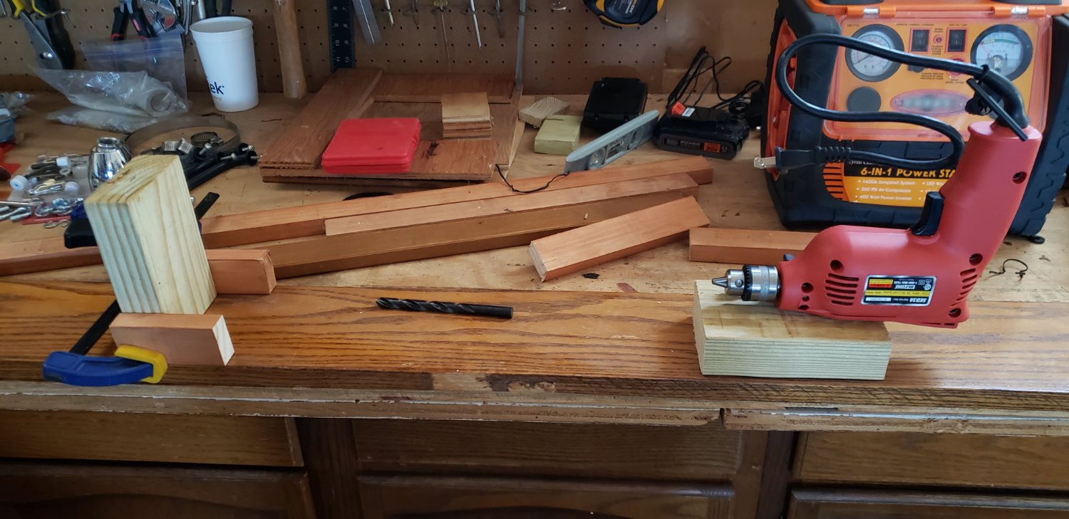
The attached image shows a VERY basic mock-up of what I plan to do. But it shows enough to give you an idea of where I'm going with this. Plan bullet points: - Headstock and drill (on the right in the image) -- Mount the drill upside down -- Build a frame around it to keep it perfectly level and steady in terms of the tailstock's "depression" that will hold the other end of the dowel (more on that in the "Tailstock" section below) -- The drill's trigger will be easily accessible, and -- The drill must be perfectly level in relation to the point on the tailstock that will keep the dowel steady (more on that below in the tailstock section) -- Mounting it upside down allows for the cord to keep out of the way. go where I want it to, and -- The trigger and trigger lock are still easily/comfortably accessible with the drill in that position. -- The drill does not have variable speed control and runs at 4800 rpm, so I'm going to get a dimmer switch (switch is 5 Amp, drill is 3 Amp), cut the drill cord, and wire the switch inline between the drill and power source -- The dimmer switch will be mounted to the right of the drill on the platform/base of the lathe - The Tailstock -- Obviously this needs to be adjustable in terms of the distance between the headstock/drill for the length of the dowel that I'm working with -- The clamp (on the left in the picture) is doable, but I'm wondering if there is a better solution, as currently I feel that it is a llittle too easy to rock the upright 2x4 block laterally in relation to the length of the platform -- The drill bit laying on the base in the middle of the picture is a 3/8" bit with a tapered tip. My thought is to use that bit to drill a shallow hole into the tailstock (the short, upright 2x4 on the left) as a means to keep the dowel that I am working on steady to prevent wobbling Questions and concerns: 1) What overall length should I make the base to allow moving the tailstock to extreme lengths for longer dowel tapering? (I understand that question must be qualified with information about how large of a ship might I build in the future) 2) Will a common 5 Amp dimmer switch - available at a typical hardware store - really work for this with the drill that I have? Somewhere in this forum I ran across a post last year (not necessarily posted last year) from a guy who built a similar corded electric drill-based lathe, but for the life of me I couldn't find ii. He included a dimmer switch in his design 3) Doing the tailstock right, I think, is paramount. Will the concave hole of the tapered tip of a 3/8" drill bit into pressure treated wood be sufficient? Might it need to be larger? Should I get some other, more heat-tolerant material to handle the heat created via the spinning of the dowel against the tailstock? 4) I'm thinking that the drill needs to be raised up a bit. Just a thought... ANY advice and/or suggestions will be greatly appreciated!

-
Thanks! I need to remember the great resources available here.
- 96 replies
-
- 2
-

-
- topsail schooner
- revenue cutter
- (and 3 more)