HOLIDAY DONATION DRIVE - SUPPORT MSW - DO YOUR PART TO KEEP THIS GREAT FORUM GOING! (Only 13 donations so far - C'mon guys!)
×


Peanut6
-
Posts
342 -
Joined
-
Last visited
Content Type
Profiles
Forums
Gallery
Events
Everything posted by Peanut6
-
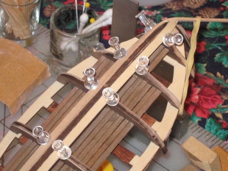
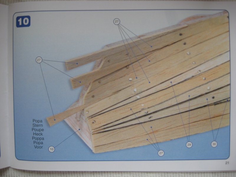
 Now I’m attaching what I’m calling my top planks. I just couldn’t get over the trimming in Step 11 posted earlier. I decided to run my planks even with the top the transom, the top of each frame member and the top of the bow cap. I’m aware that I’m getting a bit of an “upward turn” here and I’ll have to deal with it accordingly. The only thing I picked up here was using a rubber band in order to get the plank to really wrap around the corner of the bow.

- 129 replies
-
- 4
-

-
- Bounty Jolly Boat
- Artesania Latina
- (and 1 more)
-
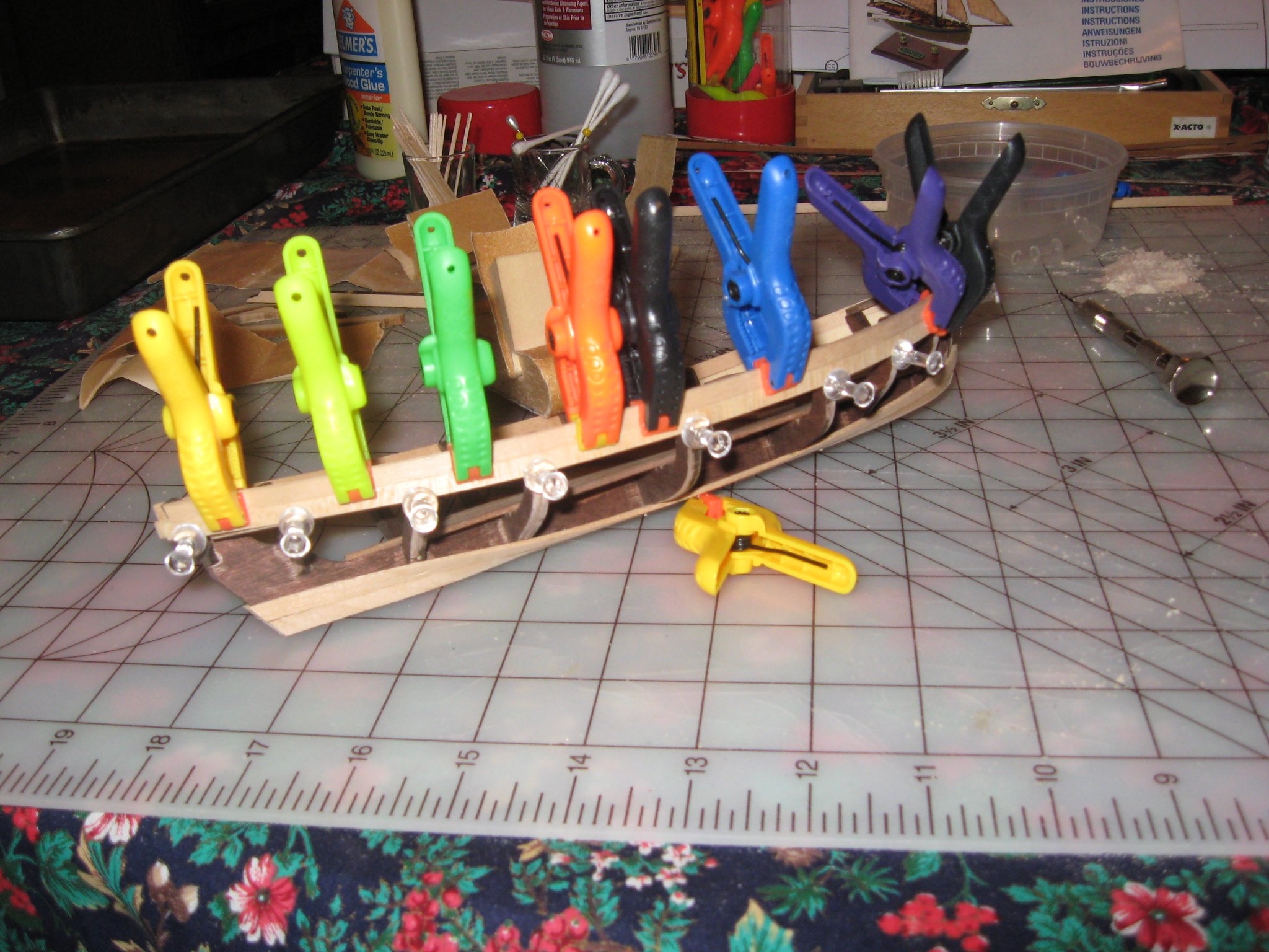
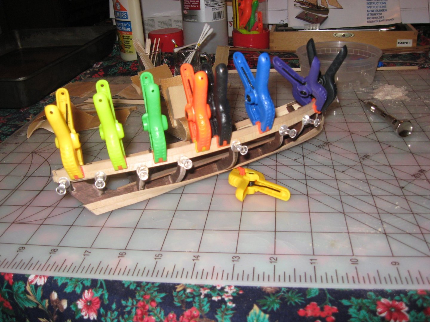
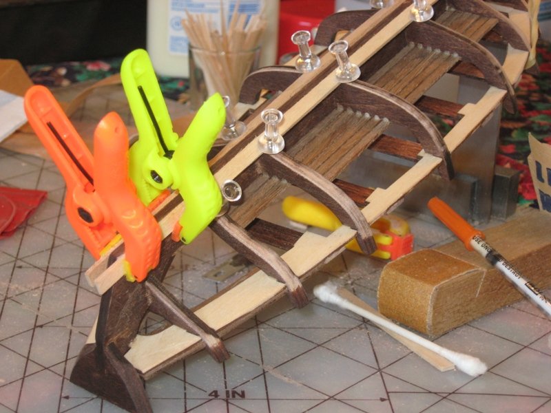
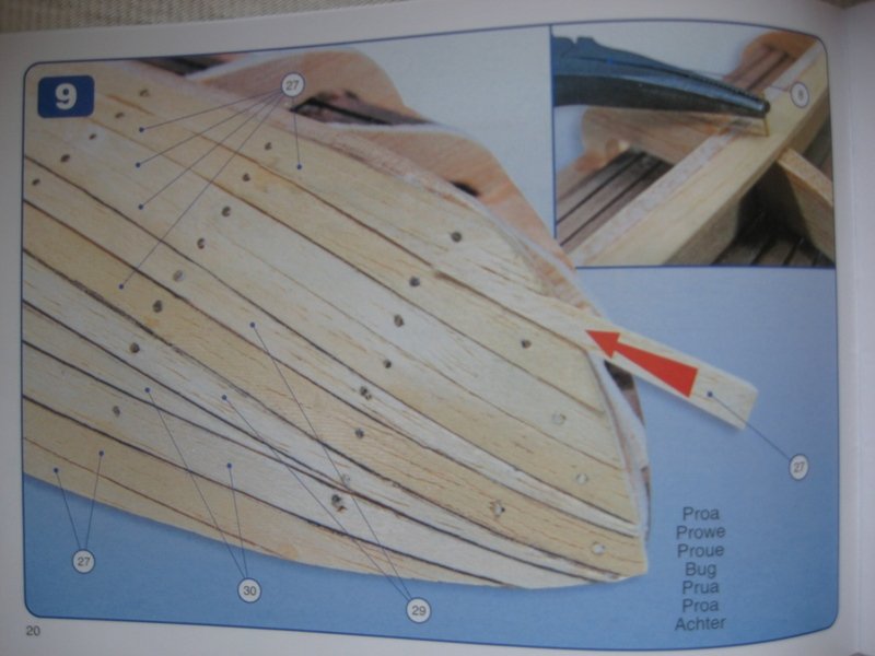
If I didn’t know better I would think my photography is improving, even if I do say so myself (I apologize for the self-promotion). This next set of pictures show bending and attaching my garboard planks. I have read many posts about how soaking planks makes them much more flexible. But it doesn’t really hit home until you experience it for yourself. But the real magic comes when you unclamp the plank after it has dried. If I was impressed at how flexible a plank becomes after being soaked I’m totally mesmerized by how it keeps it’s shape after it dries and is when unclamped. That was soooo cool. I don’t have much else to add other than a thank you to Dan Vad on the heads up about push pins and the modification thereof. Even though it may be a given to many of you, it was very enlightening and made all the difference for me. Obviously you can see my fairing and the extra drops of glue I added to the flooring battens. I also did some touch-up staining on any frame sections that I thought might possibly be visible after the hull planking.
- 129 replies
-
- 4
-
-
- Bounty Jolly Boat
- Artesania Latina
- (and 1 more)
-
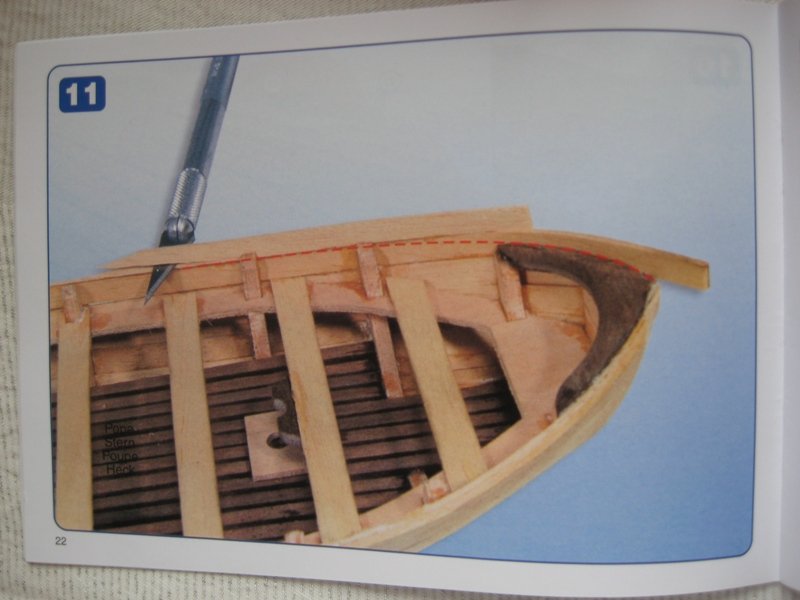
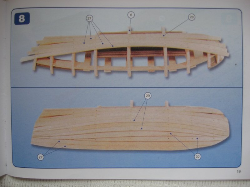
Steps 8-11 deal with hull planking. I’ve read enough to know that what they are telling me to do is no where near accurate (as if this kit is accurate) and I don’t like the look of it anyway. I can’t get over the insertion of wedges shown in steps 9 and 10, not to mention the preshaped planks. Granted I’m very new to the hobby, but it just doesn’t make sense to me to trim the top plank down as shown in step 11. Whether that would truly be done or not is beyond me. From the very beginning I knew I wasn’t going to paint the hull. I just love the look of wood and the contrasts they can present. So with all that, I’ve decided to try something different. I’m sure my approach is just as inaccurate but I’ve made up my mind, especially since I can see it when I close my eyes. I’m going to try to incorporate some best modeling practices, some pseudo accuracy and because I’m not painting my hull I hope that the end result will be more aesthetically pleasing than what is being offered. I’m going to use the planking they provided, accurate or not regarding size. I’m going to go 1 plank, bow to transom, not tapering a plank less than half the provided width and work stealers and/or drop planks where I need them.
- 129 replies
-
- 4
-
-
- Bounty Jolly Boat
- Artesania Latina
- (and 1 more)
-
Ok, back to fairing. During this process I continued to pop loose the flooring planks. I finally decided enough was enough. I loaded up a hypodermic needle and hit both sides each floor plank to frame interface with a drop of glue. Something I should have done earlier, but that combined with a continued effort to look at how I was handling the boat seems to have put an end to that issue (I certainly hope). I finished the fairing and hope I haven’t made a big mistake. After the fact I took a look at the plans. The placement of the top plank in reference to the upper most portion of the frame members start to show a bit of a gap between the plank and the deck as you go back to the transom. I look at my boat and I don’t see that same gap. It could be the angles working with my head since I don’t have it planked yet. I guess we’ll see when all is said and done. I feel pretty good about how it came out since it appears that I’ve taken care of any bumps, dips or doodles using my temporary battens as a guide. I’m hoping that if I have taken the frames down to far it won’t pose a serious problem. Like I said earlier, I was so excited about my batten discovery that I forgot to get pictures.
- 129 replies
-
- 3
-
-
- Bounty Jolly Boat
- Artesania Latina
- (and 1 more)
-
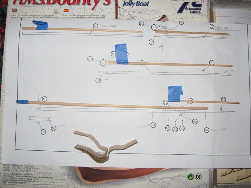
During my times of contemplation (ok, scared to continue and I’ll admit it) of the fairing I looked a little forward into the build to see what I could do to clear my mind. I decided that I could be turning down the 3mm, 4mm and 5mm diameter dowels that make up the mast assembly, bowsprit and spars. Advisory note #1: The instructions discuss making/sizing your sails per the included plans. My kit, as well as others, came with pre-made sails which are larger than the dimensions of the plan. This means that at the very least the boom and halyard need to be longer that what the plans state. Be sure to double the check provided sail size versus plan sail size and make adjustments at least to the halyard and boom accordingly. And it wouldn't hurt to take a look and bowsprit and mast length. I'm my case I hadn't yet cut the bowsprit to length so I was able to use it as I had originally turned it and I decided to go with a single piece mast rather than the two piece mast per the instructions and adjusted accordingly. I’ve read many ways that this can be done. With the materials/tools at hand, I decided that my cordless drill would do the job just fine. There was only 1 thing that happened that totally surprised me, and 2 I should have thought of. As far as “should have thought of” goes, number 1 is I didn’t realize it doesn’t really take a lot of pressure to dent wood. Even though I wrapped the end of the dowel with a few layers of masking tape prior to chucking it up I still went a bit too tight, which left dents in the wood. This of course leads to point number 2, if you need a 200mm dowel tapered and the kit provides a 200mm dowel you might as well get a longer dowel to start with. Giving yourself extra length before and after allows you to take care of any unforeseen events. I started by getting a sheet of 150 grit sandpaper and ripped me off a strip about 30mm wide and the full long length of the sandpaper. I took that strip and folded in half and then in half again. Basically I wound up with a sandpaper pad 30mm wide by how ever long the folds came out to be. I carefully wrapped the sandpaper pad around the dowel closest to the chuck using my thumb and index finger and work my way to the free end. As time went by I was able to adjust the speed of the drill to find the happy medium of making good progress yet still being in full control of what I was doing. I kept taking measurements with my calipers and getting a fresh surface of sandpaper as I needed it. One thing to be very careful of, if you are getting close to your desired tapered dimension and present a fresh surface of sandpaper you can very easily taper too much. It almost cost me a dowel. I was able to get within 0.02mm of my desired dimension and then I switched to 220 grit to take care of the last little bit. And on one dowel that is where the unexpected happened. I was making my last pass at the far end when all of a sudden the last inch or just bowed. The only thing I can figure is that I hit that perfect place at the perfect diameter where the wood grain changed. Fortunately I had enough at the chuck end of the dowel to make the adjustment and still use what I had. Advisory note #2: What I've learned since this post is that heat has a fantasmigorical effect on wood. If you were amazed, as I was, by how flexible a piece of wood becomes when you soak it in water, wait until you see what applying real heat will do. I'm now firmly of the belief that the instant radical bowing of my piece was due the heat created by friction. In hind sight I think I want to remember feeling the sandpaper getting warm/hot but not enough to prevent me finish up the pass (boy was I wrong). When the hot sandpaper hit the warm wood everything went wacko. In turning my new pieces I took extra care to ensure that the wood wasn't getting very warm and as soon as I felt any heat in the sandpaper I moved to another section. Following this practice I had no issues even getting down to 2.2 MM in diameter. Advisory note #3: This is a follow through from the Advisory Note in post #6. Take note of the location of the bowsprit support (item #58) shown in the mast portion of the picture below. The instructions advise us to take measurements from the plans for tapering of the items shown below. On my turning of my single mast, adjusted for the larger sail issue, I got it turned to the appropriate diameters per the plans (again you need to refer to post #6). I added the cheeks at the plan scaled location from the top of the mast. I also took this opportunity to add the the bowsprit support (item #58) located as scaled from the plans. Here is where the rub is. I aligned the bowsprit support to be centered on the mast, in line with the cheeks as shown in the top view on the top left of the plans, at the elevation as scaled from the plans. This posed a problem at the mast installation, as I had oriented things. The elevation, as scaled from the plans, aligned with the cheeks does not account for the truss reinforcement installation. If you look at the side view of our Jolly Boat at the top right view of the plans you will notice that the bowsprit support is located just aft off center. Does offsetting the bowsprit support, as shown in the plans, clear the truss support (item #58) when located from the bottom of the mast when measured? I don't know as my location was unacceptable and I had to remove it. I've decided to reattach the bowsprit support after I get thru my hornets nest of problems at the mast installation step. The plans show conflicting information so be careful where and when you position/orient this piece to take full advantage of all possibilities available at the time you decide so to avoid problems.

- 129 replies
-
- 4
-
-
- Bounty Jolly Boat
- Artesania Latina
- (and 1 more)
-
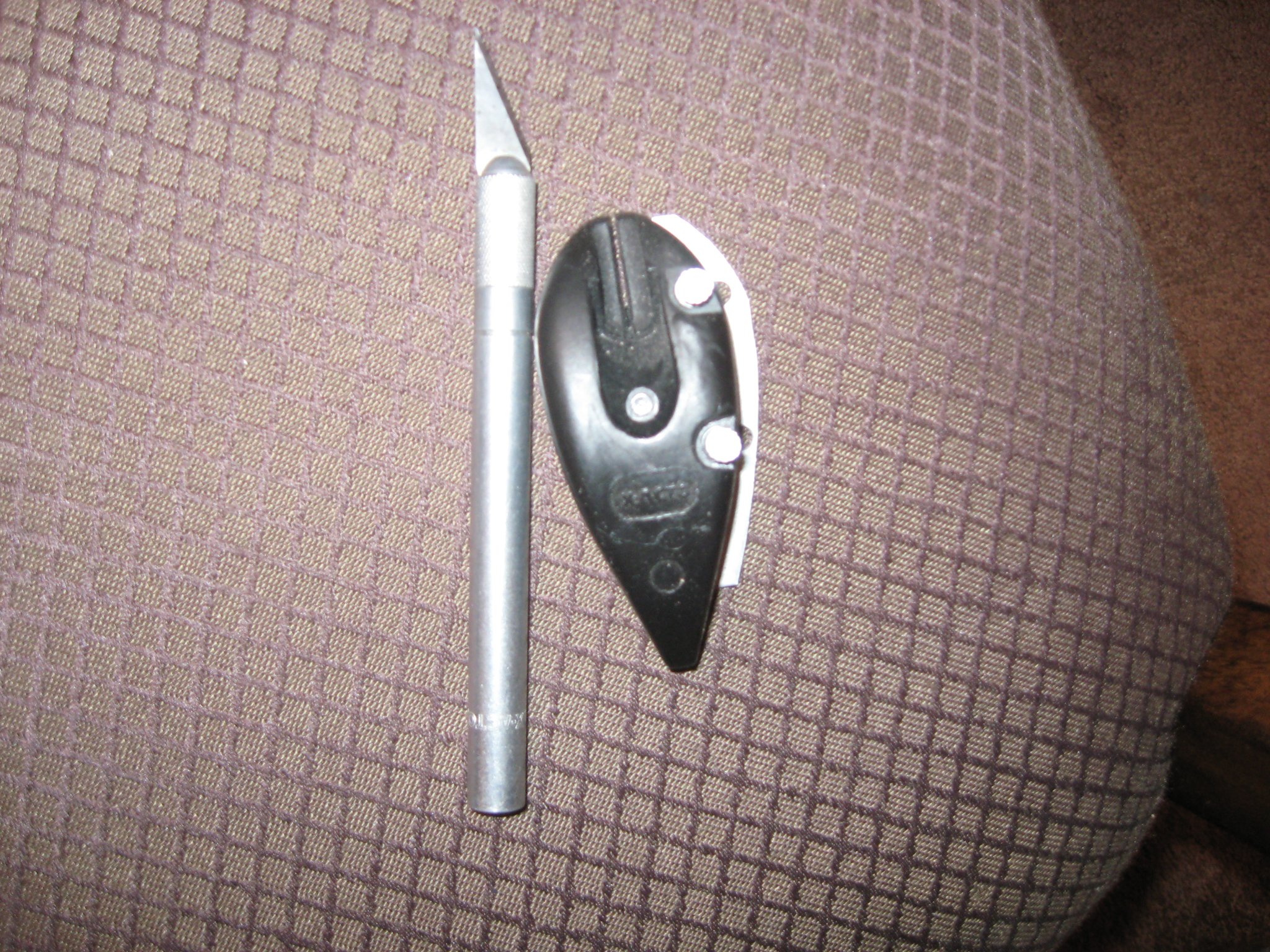
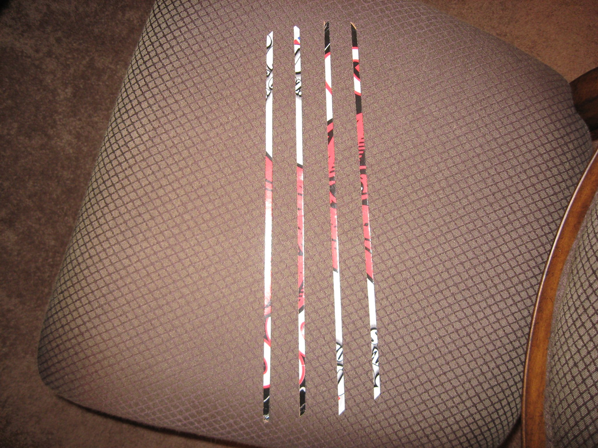
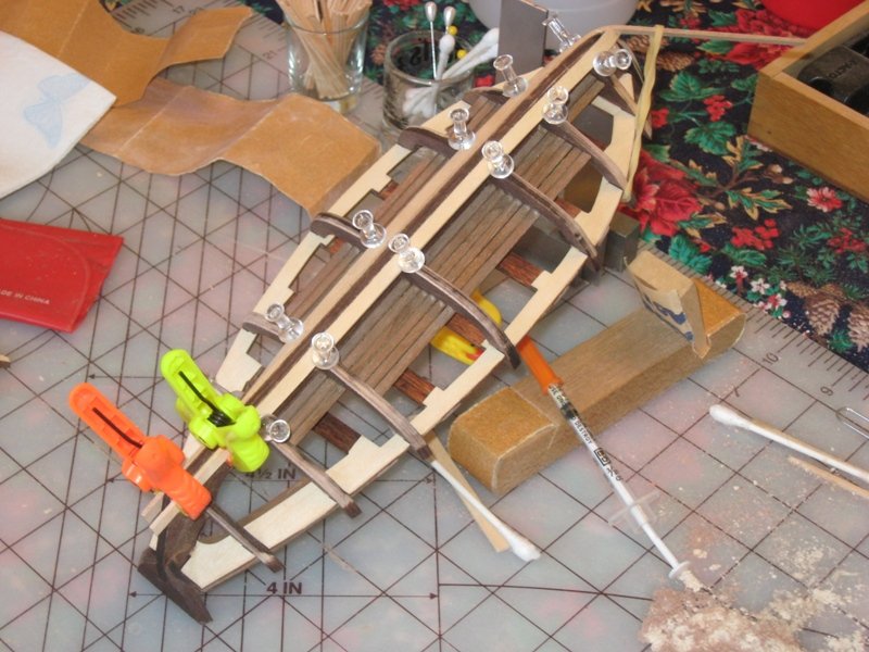
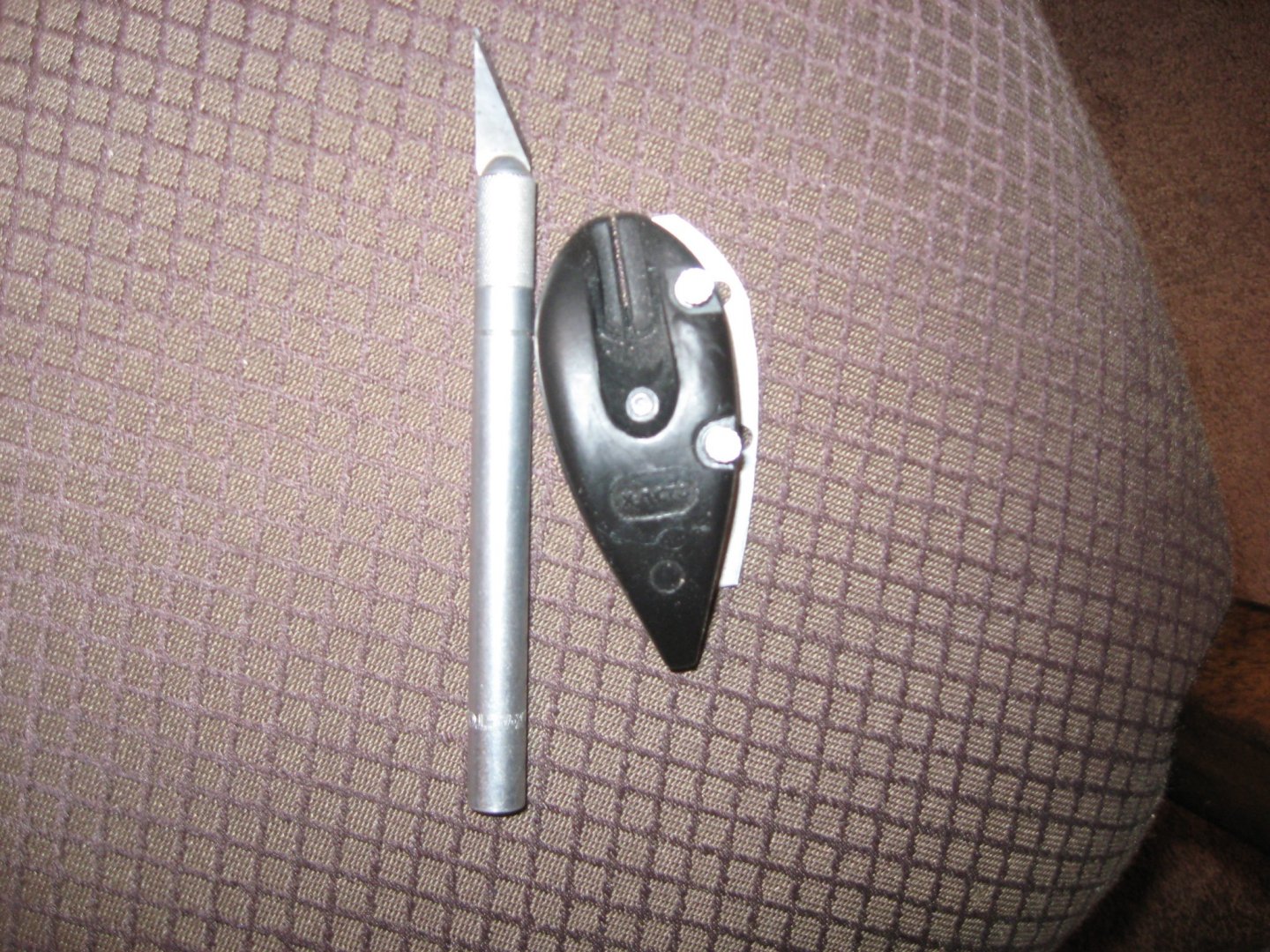
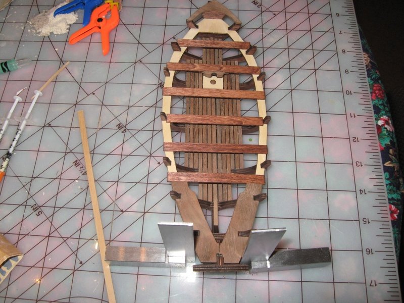
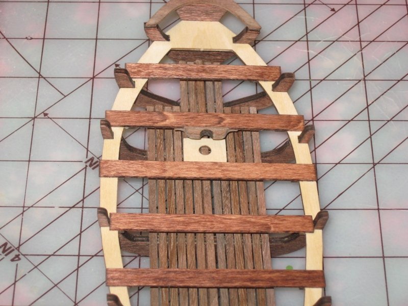
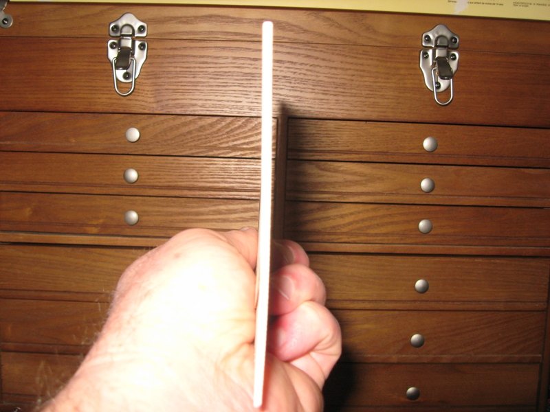
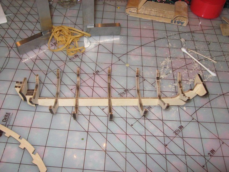
Steps 6 & 7 are where we fair the frame starting at the bow and working toward the center of the hull. Then we go from the stern to the center. With everything I had read this was going to either make or break the appearance of the boat especially since this is a single planked hull. So of course I’m scared to death. I do more than enough reading than one should be allowed without ever touching any type of abrasive material/device. I finally decide I’m being a baby about this whole thing and start making sawdust. I wound up going against the instructions in that I did one entire side first. I was using a plank to check my progress. That worked fine over the distance of 3 or 4 contact points. I don’t have a keel clamp of any sort and my little hands just aren’t big enough to hold the boat and the plank in enough places over a greater distance to get a good idea of what I was doing. And like I said, I was using a less than an ideally flexible plank. Because I’m anxious about this whole fairing thing I decided to walk away to have a smoke and a frosty mug of the golden nectar while I think about how I can cover a greater length with what I have available. As luck would have it I was close enough to the end of the 30 pack in the garage frig to move the few remaining cans from the box to a shelf leaving me room to put the next box in its place. So here I am staring at the empty box while I’m sucking my suds and burning one. I get to thinking and the wheels start a turning. I bet the cardboard of that box would be flexible enough yet still have some rigidity to work as a temporary plank. I finish up my smoke and tear off a section of the box, straight away to the shipyard. I find my balsa stripper (that is what X-Acto calls it) and cut some temporary planks. I can hold one end at the bow with the other end at the transom and with just a bit of tightening I can see every bump, dip and doodle along the entire length of that section of the frame. Wow, I just amazed myself, this just might work after all. Even though I have that worked out I was really getting concerned at how much I was having to take of the transom to get a smooth run to the 2 frame members leading up to it near the keel level. Unfortunately I was so excited about this discovery that I neglected to take any pictures of my progress.

- 129 replies
-
- 3
-
-
- Bounty Jolly Boat
- Artesania Latina
- (and 1 more)
-
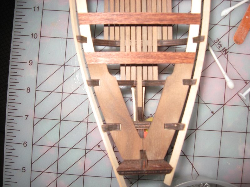
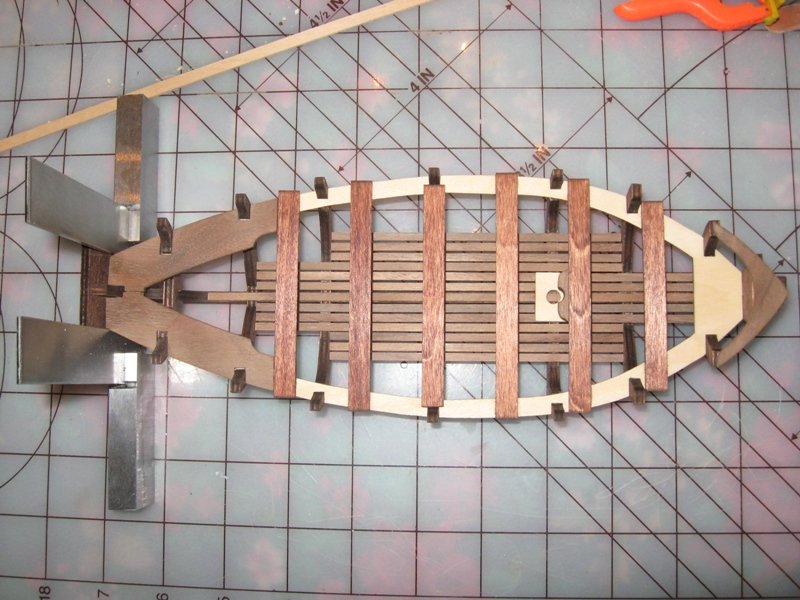
Steps 4 & 5 add the mast hole cover, thwarts, the mast base and reinforcement. These steps were pretty straight forward. I decided that I didn’t like the look of the thwarts and the deck being the same wood tone. I cut them just a hair longer than required and stained them the same as I did the frame. While they were drying I The mast hole cover is centered at the intersection of the center line and frame 5. The instructions tell you to attach the mast base to the bottom the thwart and then attach the reinforcement on top of the mast base butted up against the thwart. Like I said, pretty straight forward and not difficult. Just make sure you get them all aligned. I continued to pop loose a floor batten now and then. When will I learn to pay attention to what I’m doing. Advisory Note: This is what I did and it posed problems when it comes time to install the mast. I installed the mast base and reinforcement prior to installing the mast hole cover. I used the 5mm dowel to help me align the mast hole cover. I put the end of the dowel in the hole of the cover and then snugged the dowel against into the radii of the base and reinforcement. My thinking was that the base and cover surfaces would present a sufficient surface to ensure the mast would be perpendicular. And that it did, but . . . . later on at the tapering step you're instructed to measure off the plans to get the taper. What I did was take measurements along the length at various points to guide me to the final diameter. What I didn't know at the time was that the tapering actually starts after the mast passes the thwart, base and reinforcement section (I went back and double checked the plans to be sure). When I came to tapering the mast I started the taper right away just a hair past the 5mm point. By the time the mast gets to the base and reinforcement section you have taken enough material away so that when the mast is snugged against them you have a forward rake on the mast which is wrong. At this point in my build I'm trying to decide if I want to try and shim the area between the mast and the base and reinforcement section or detach the hole cover and reposition it. At this point in my thinking either method could/should eliminate the forward rake but I don't know for sure. Would hate to see someone come across the same problem(s) I've had especially if I might be able to help them avoid the problem. I didn’t pick up anything new nor did I have any problems.
- 129 replies
-
- 4
-
-
- Bounty Jolly Boat
- Artesania Latina
- (and 1 more)
-
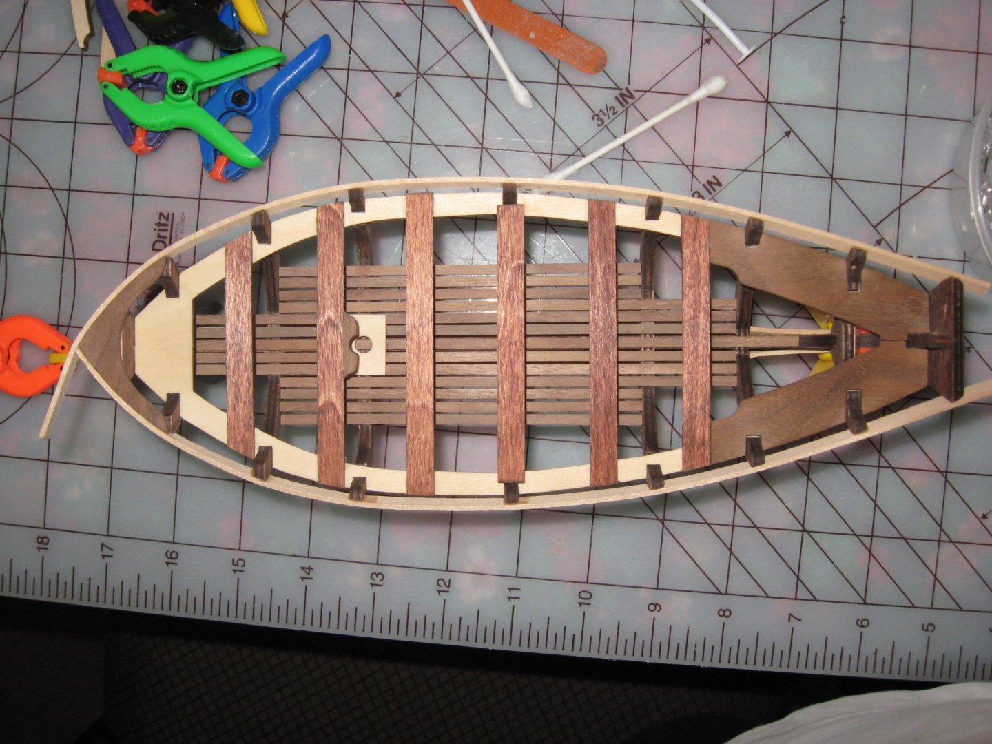
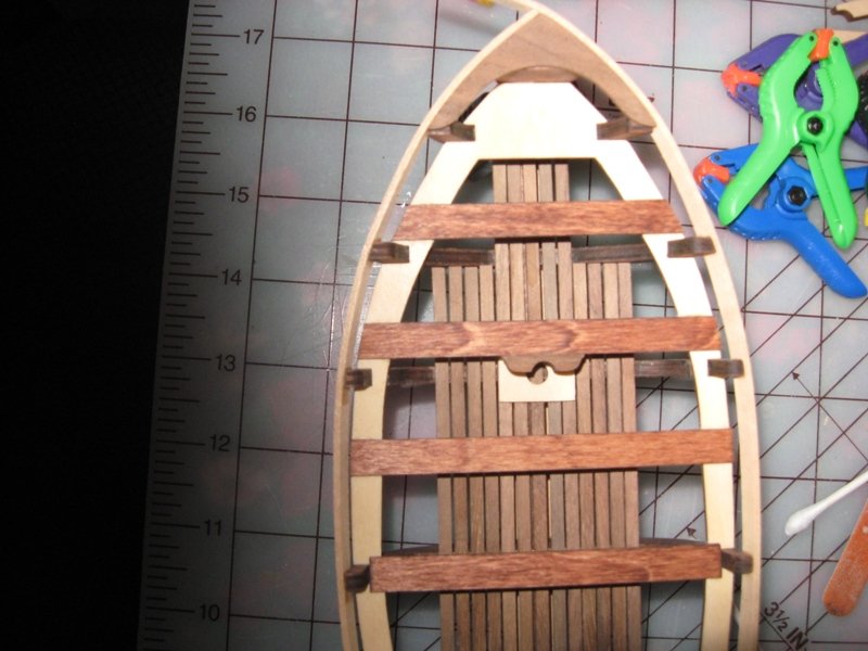
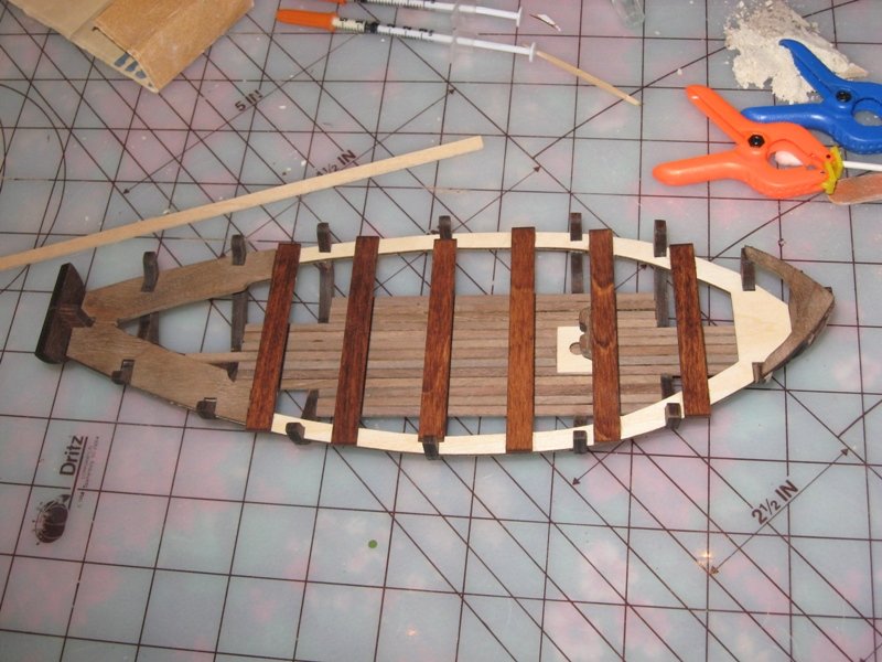
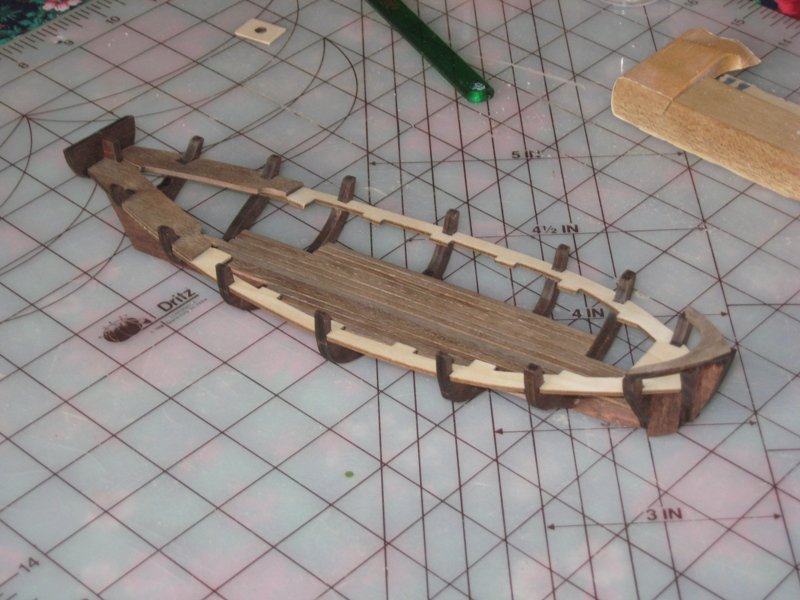
Step 3 installs the centerline, flooring battens, batayole (their description) and the stern thwarts. All pieces are African walnut. I cut all the flooring battens just a hair long and sanded each one individually to desired length for their location. I measured the spacing from the plans and figured I would need a spacer to ensure consistent spacing. I used the left over piece from the centerline, sanded it to the appropriate thickness then cut it into thirds. After the centerline was set I glued down the first batten. The spacers worked as I had planned. After the first batten was set I placed its counterpart on the other side. This time one of the spacers got clued in place, and this turned out not to be the only time. After getting a couple battens in place on each side I abandoned that method and just went by eye with no problems. The only issue I had was discovering how you must be very careful what you are holding on to. I kept popping loose battens because I would be holding or pushing on them. The stern thwarts didn’t fit into position exactly as I had wanted. I decided trying to get them to fit exactly the way I wanted them would make the look worse than how they currently fit so I just went with it. I thought I had made a major error when I went to attach the batayole. The instructions show that it rests at the very tip of the bow and back to frame number 3. Frame 3 sits lower than the bow and I went into immediate panic. I looked at the plans and saw that the bow and frame 3 would need to be co-planar since the batayole sits at a slight angle. Got things sanded down so the batayole rested on the 3 surfaces indicated in the instructions. Lessons learned: need to be more careful in how I handle the boat, popping pieces loose is very frustrating. Repercussions: None, other than loosing time having to reattach flooring battens.

- 129 replies
-
- 4
-
-
- Bounty Jolly Boat
- Artesania Latina
- (and 1 more)
-
Step 2 is where I attached the deck. When I found the sheet that contained the deck it looked warped. I believe it was due to the shrink wrap. I set it down on my work surface and went to refresh my memory on the best way to straighten a warped sheet. Wasn’t able to get back to it until the next day. I was surprised to see that just letting it sit over night it flattened itself out. Removed it from the laser cut sheet and sanded the nubs down. I looked at the singe marks and decided the exterior edge wasn’t an issue since it would be covered by the planking but the inter edge was a different situation. There are short tabs where the thwarts sit and I saw the same situation of those corners being rounded down if I tried to remove the singe marks. In hind sight it wouldn’t have been a big deal because the thwarts would have covered them. Why I could recognize that for the exterior and not here I can’t tell you. Regardless, it was a snap decision to leave it alone and let it be. The deck is symmetric so I only sanded the side that I decided would be showing and marked the opposite side with an “X” in pencil. I did a dry fit and all was good. After the dry fit I set the deck down on my work surface sanded side up knowing that was the orientation I wanted. I figured that I could easily use rubber bands to attach the deck to the frame and promptly applied glue to the mounting surfaces of the frame. I get the deck seated and start applying rubber bands and find that the majority are either to large or too small regardless of how I position them, doubling them or not. Now I’m in a bit of a panic, during this process I’ve smeared glue just a bit and it is starting to set. I pull off the deck and start cleaning off glue. Got the frames and deck cleaned up nicely. Now since I was cleaning the gluing surface of the deck (the side with the “X” on it) it was left on my work surface “X” side up when I was done, opposite of what I had imprinted in my mind (yeah you see it coming don’t you?). Based on what I learned on my first attempt I identified the appropriate sized rubber bands and their locations for my second attempt. I applied glue to the appropriate mounting surfaces of the frame, attached the deck and secured it using the size rubber bands. I set my modest assembly down on my work surface after making sure all was right, or so I thought. Turned off the lights anxious to see it again tomorrow. What I see the next day is very discouraging. Half of the mounting surfaces didn’t take or if they did they do so in the wrong place, meaning they had crept up the frame no longer in contact with the correct mounting surfaces. I used isopropyl alcohol to neutralize my glue and clean things up. I had learned that isopropyl alcohol is just as effective as water in neutralizing water soluble wood glue but doesn’t cause the wood to swell which can present additional issues in disassembly. Finally get things cleaned up and clamped down appropriately using spring clamps where the rubber bands just weren’t working. I was able to position the spring clamps with one jaw on the outside of the frame, flip the flexible pad out and position it on the deck. With a little work I found just the right location along the frame to ensure the deck was in full contact with the frame mounting surfaces. After all was set I removed the clamps and rubber bands only to see my wonderful little “X” staring me in the face. Nothing left to do but carefully sand down the deck with it in place. After all the trouble I had getting the deck correctly attached there was no way I was pulling it off. Evidently I didn’t get any pictures of this step other than the warped sheet. I suppose it was because this step kinda’ put me in a tizzy. My inexperience really came to the forefront and every little problem that I had was of my own doing. Lessons learned: The dry fit of parts is a given but serious consideration should be given to a dry clamp. If you are not 100% sure that your dry clamp is secure, walk away and let it sit a while and then check it again. Maybe a bit longer than it takes the glue to set up. Rubber bands have a tendency to travel if the surfaces aren’t parallel. Might only be just a little bit, but that little bit can make all the difference in the world. Learn about your tools and what they are capable of. I found, by accident, that by flipping the flexible pad on my spring clamp in the out position it presented many new clamping options. Repercussions: I was able to overcome everything that happened but due to my mistakes it cost me 3 days of forward progress.
- 129 replies
-
- 4
-
-
- Bounty Jolly Boat
- Artesania Latina
- (and 1 more)
-
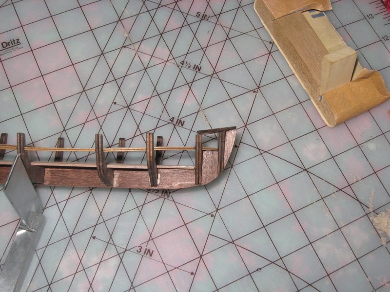
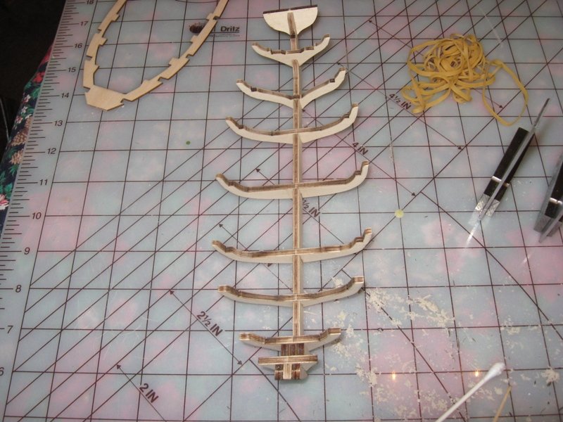
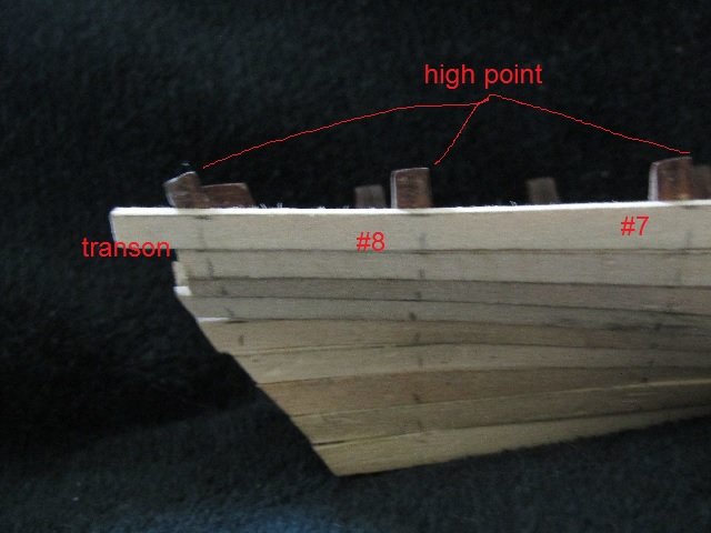
Step 1 has me attaching the frames, transom and reinforcements to the “outer keel”. These were provided in laser cut sheets. I thought this was pretty cool, only had to cut thru the little sections left to retain the piece to the sheet. Simple task and I sanded down the nubs from the bridges. Before doing any additional sanding I tried a dry fit of the frames to the keel and was very surprised how tight the fit was. I actually had to work a bit to get all the frames fully seated. I figured now was the time to find out how square things were fitting together. I pulled out both of my hobby squares checking every surface. I then borrowed some of the kids Lego’s to figure out that method. I was amazed that my naïve eye was finding everything was straight and true. With a bit of work I was able to disassemble everything. I recall reading somewhere that it was advised to remove the singe marks left behind after the laser cutting because it poses problems for gluing. It appeared that the singe marks actually impregnated into the end grains of the ply of the keel and frames. There are a couple very subtle surfaces on frames 2 (nearest the bow) and 8 (nearest the transom) which are used to mount the deck. The other frame members have larger surfaces. As I was trying to remove the singe marks I noticed that I was starting to round off the defining corners those surfaces on frames 2 and 8. I couldn’t very well leave odd colored wood due to singe marks so I decided that I would stain the keel and frame. I selected Minwax red oak #215. Glued everything together, wiping away excess glue with a cotton swab (Q-Tip) as I went and let it dry. Once it was set I stained my frame and let it dry over night. ADVISORY NOTE: You need to take notice of the chamfer at the top of the transom and the high points at the top for frames 2-4 and 6-8. The high point of the chamfer on transom should be on the outboard side. Frames 2-4 need to have the high point on the bow end and frames 6-8 need to have the high point on the aft end. The top of frame #5 is horizontal so no worries there. I noticed I had something wrong at the transom when I was nearly done with my planking, see post #28. Hopefully the picture below will show you what I mean and what not to do. Lessons learned: Just because you use a wiping agent doesn’t mean you got all the glue removed. Best to hit it with a damp wiping agent and then some sandpaper to ensure you’ve got it all. Repercussions: None, I was very lucky this time because all locations where the stain didn’t take because of glue residue will not be viewable.
- 129 replies
-
- 5
-
-
- Bounty Jolly Boat
- Artesania Latina
- (and 1 more)
-
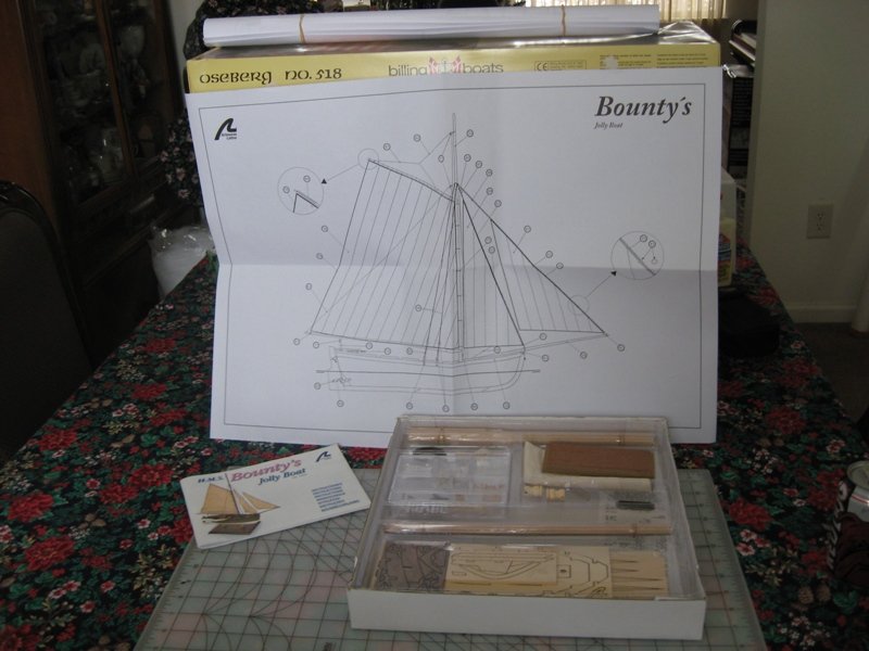
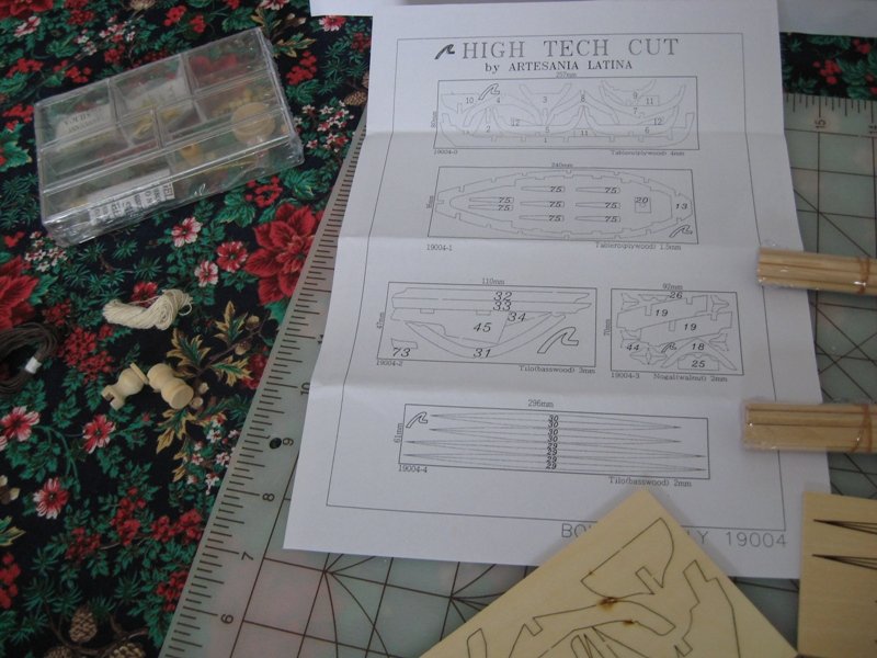
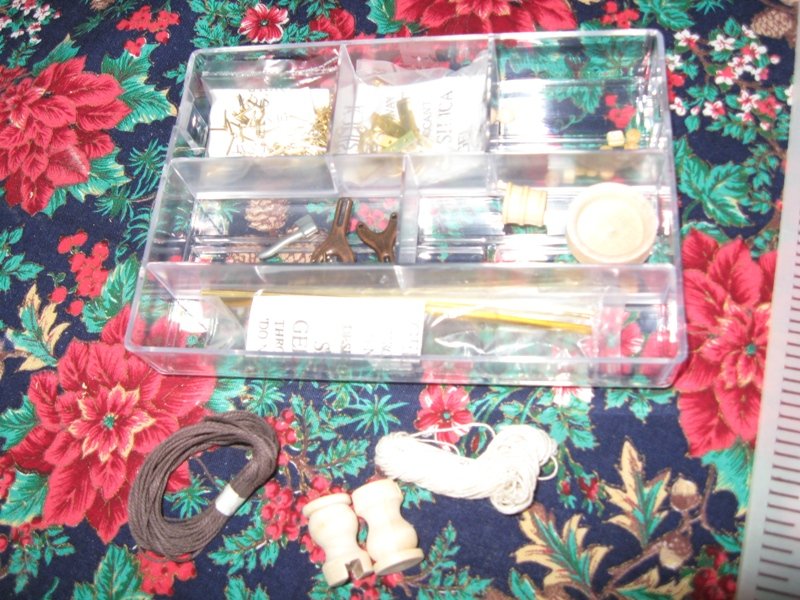
I’m finally getting my build log started. This is my first build so I’ll be asking many questions once I get my log caught up to my current state. As I understand it, one of the greatest benefits of a build log is providing a source of reference for other builders of the same model. I’ve read many logs and get a bit dismayed because the majority of the time because you only see what was done and not how it was done. I believe success is always found in the finest of details, the things that one of experience just knows or is so basic that it’s assumed to be obvious common knowledge is often omitted or glossed over at best. So from that point of view I’ll be including what I’m thinking, wondering, questioning during each step of the construction as best as I can. I will also include all the little things I had to deal with, silly things I learned or should have taken into account if I had been thinking. I didn’t despair because I know this is a learning experience and the only way to learn is by doing. Whether my thoughts/concerns and the little things I find out are valuable or not, I think it still might be of help to others, if nothing more than to give them something to laugh at. So with all that being said, enough of the preamble and let’s get on with the show. AL’s Jolly Boat is supposed to represent the boat that Captain Bligh and his followers were set adrift in by Fletcher Christian and his mutineers of the HMS Bounty. I’ve come to learn that Model Shipways Bounty Launch is much more representative of the actual boat that Captain Bligh and his followers started their miraculous voyage. Here are the specs of AL’s Jolly boat: Length: 415mm (16 5/16’) Height: 363mm (14 3/10”) Beam: 340mm (13 3/8”) Scale: 1:25 (12/25” = 1 ft) I really can’t give an intelligent comparison of the contents of the kit since this is my first build. What I can say is that all planks and dowels were banded and shrink wrapped separately (meaning all dowels together and all planks together). All the sheet material was shrink wrapped together as well. All small components were in a compartmentalized plastic container with all like brass components bagged along with a silica gel packet in each bag. Regarding the quality of the wood, good I suppose. I didn’t see any knots in the wood or rough grain areas. Inventory showed that all components were included. The one thing I noticed was that the dowels used for the mast pieces, bowsprit, spars and oar handles were listed in the parts list as being African walnut were actually a light colored wood they refer to as Ramin. The pre-sewn sails came in their own bag. Being inexperienced I have nothing to say about the sails, guess I’ll be able to give an opinion a couple builds down the road. All the components in the sheet pieces were laser cut. This is the first I’ve seen and was very impressed. Here are the customary pictures that appear to be required to start all build logs.

- 129 replies
-
- 6
-
-
- Bounty Jolly Boat
- Artesania Latina
- (and 1 more)
-
Preface: This is a recreation of the build log I started in late 2010 up to the close of dry dock in the summer of 2011. As stated in my reintroduction post, I've gotten the itch back and want to finish this project. I had saved all the text and photos from that original build log and have decided to use them as is/was. I won't edit anything and will include the photos as best as I can determine which post they belong to. My aim is to get us back up to date with the current status and then press on to completion. It will become obvious that I received a lot of help and feedback, but those posts have been wished to the cornfield due to the "Great Crash". I apologize in advance for my lack of photography skills and lengthy posts. I would greatly appreciate any and all comments plus your advice in the completion of my little Jolly Boat. Take care and be safe. kev
- 129 replies
-
- 5
-
-
- Bounty Jolly Boat
- Artesania Latina
- (and 1 more)
-
Allan, thank you for your reply. I believe I should provide more information for clarity purposes. I was planking my first build, Bounty’s Jolly boat. I was only soaking my strakes in order to bend them to shape. I was not applying heat in any fashion and was getting very good results. But when I realized my FUBAR point in my planking I closed up dry dock for about 10 years. Additional info can be found in my reintroduction post. While trying to compose my reply I believe I had an epiphany that explains a lot. That being the accumulation of a series of small procedural errors, false assumptions and the main reason why you should always band the hull. But there is just one thing I would like to know, just because. I’m aware of the need to trim the strakes as needed. So if at a frame member the strake needs to be trimmed to 4.5mm, I soak the plank, applying no heat, and clamp it down to form it. It dries and I measure the plank again at that particular frame location, will it measure 4.5mm? Take care and be safe. kev
-
I would like to apologize in advance if this post appears a bit ambiguous but it is my attempt to prevent it from becoming too convoluted. Please be patient and bear with me as I can’t figure out how to throw everything out and have it understood. I figure that offering this “meal” course by course would be easier for all those who dare to participate. 1st question, if I soak a 0.5mm X 5mm strake for a period of time, when dried will it return to its original dimensions or could it be slightly smaller or even slightly larger? 2nd question, would an “over soaked” strake present a flat spot or strake run between frame members? 3rd question, if one were to start at the garboard and work your way up, on the next strake you bevel the garboard side interior edge so that the garboard side exterior edge abuts the deck side exterior edge of the previous strake, wouldn’t the remaining distance along the frame increase ever so slightly and accumulate over each strake installment? Take care and be safe. kev
-
Permission to come aboard . . . . again
Peanut6 replied to Peanut6's topic in New member Introductions
Mark, thank you for the link. Back then I had done all my instructional reading of the available info on MSW plus I picked up a few books at the discount book store. I admit there were a couple things I did that weren’t exactly “by the book” but I found within other build logs how handle them. As embarrassing as it is to admit, the cause of my problem wasn’t procedure but execution. I was planking correctly but toward the bow I only measured from top of frame to end off lumber, not to same reference point I used for the other frames. Now to put some egg on an already crimson face, I got the measurement correct at the transom. I have no clue what happened to my thinking process from transom to bow. After talking this thru with myself and double checking what I found, we’re both laughing at me. I’ll go into greater detail of the FUBAR when I get my build log going. Take care and be safe. kev -
Permission to come aboard . . . . again
Peanut6 replied to Peanut6's topic in New member Introductions
I am greatly comforted by all the warm re-welcome comments. I shouldn’t have expected anything else based upon my previous membership, but sometimes you just never know. I’ve read every build log of the Jolly boat in hope of discovering the cause of my current planking situation, which was the last straw in the decision to step away from the project for awhile. Of course I hadn’t intended my break to be this long. I’ve picked up things I wished I would have done, things I could have done later to make things easier now, things I would like to try to do and the most important are the “be carefulls”. Duanelaker, I’ve read your build log of the Jolly boat and will have some questions for you when it comes time to attach the keel parts, especially at the bow, and rigging. It is extremely helpful to be able to see a complete build log and have the creator connect, thank you. I hope to do as fine a job as you did with you build log and that my ship turns out as nice as yours. BobG, I can’t imagine what Noblesville would have been like 50 years ago, though I have seen pictures. We’ve only lived here for 25 years and it has changed so much just in that time. Ironically, we came from California. I spent many years in the Antelope Valley area and we met in Indian Wells Valley. For those that aren’t familiar with California, we were basically in the middle of the Mohave Desert. Hot as all get out but within a relatively short drive to whatever you would want. I’ll recreate my Jolly boat build log as is/was. I won’t even fix the typos or syntax errors. I think I’ll just add a preface to explain a few things, give a current status and then just move on (hopefully this time) to completion. It’s great to be back and boy did I have a major series of “Aha moments” this morning. I’ll share those in my build log recreation. I believe they will solve all my current planking problems. Next onto the planking forum for a few questions. Take care and be safe. kev -
I originally joined MSW back in the fall of 2010 going by the name Firebirds. I had started a build log of my very first build, Bounty’s Jolly boat by AL. All these years later I’m getting the itch to pick up where I left off. I plan on recreating that build log as I saved all text and photos. I wonder if I should recreate it as is/was or edit the text to better align with my sampling of current build logs. My style was a bit different back then and even more so from what I currently see. It might be fun for some to see what was as it was back then. I’ll leave it up to those who choose to comment. What I mean is I approached my build log based upon a couple facets of my background. From my engineering documentation side I wanted to ensure that when I decided the log is complete it would contain all details of each step from the opening of the box to completion/display. From my coaching side I wanted to make sure that I not only showed what I did and how I did it, but more importantly why I was doing it that way. It also contains some conversations I had with myself. I’ve left out quite a few details in this reintroduction to the group. Specifically how I got to where I was when I closed dry dock and what happened to regain the itch to start again. Hopefully I will be allowed to fill in the blanks in later posts. Ping to the current member know as Peanut: If my current identification name gives you any moment of pause (as it could pose some confusion), please let me know and I’ll see what magic the moderators can do to take care of the situation. The last thing I want to do is be the cause of any waves. Take care and be safe, kev