HOLIDAY DONATION DRIVE - SUPPORT MSW - DO YOUR PART TO KEEP THIS GREAT FORUM GOING! (Only 13 donations so far - C'mon guys!)
×


Peanut6
-
Posts
342 -
Joined
-
Last visited
Content Type
Profiles
Forums
Gallery
Events
Everything posted by Peanut6
-
 did you happen to get the PM I sent you?
 -
I was very pleased with how Granpa's fly tying line worked out for me. So glad I got 3 spools, all of which are nearly full. Looking forward to seeing the pics of your rigged cannons when you get them done.
-
When you get finished with this build, can we consider you an armament expert?
-
Hey HHH, so what is the cannon count now (completed vs. still to do)?
-
Great suggestion, nothing wrong with getting lucky every now and then . . . but the toothpicks have been fitted, glued and should be ready for trimming and touch-up staining in just a little bit. At least I thought ahead just a bit and tested how best to trim the toothpicks down to the thwart with minimal sanding required. If my little nippers do what I expect them to do, I won't be sanding all. But if not, my #11 x-acto blade will also work just fine. I firmly believe with the ends stained and being tight in the corners, you have to be looking for them to see them. Guess that approach is where I'm hoping to get lucky.
- 129 replies
-
- 1
-

-
- Bounty Jolly Boat
- Artesania Latina
- (and 1 more)
-
This morning I came to the realization I’ve had my Thinking Cap on backwards the last couple days. I was so focused on getting my horse for the boom tackle located then bent properly I went about it the hard way. First I located and drilled my holes thru the aft thwart into the end of the transom to a suitable depth with no problems, what a relief. Then made numerous attempts at making a “bending jig” with a piece of scrap wood from the garage and some nails. I figured a jig would be the sure fire way to accurately and symmetrically bend my horse into the desired form. Got the first bend done using a pair of round needle nose pliers just right. I found that I just don’t have the skills, materials and/or tools to create a fixture for the second bend accurate to the 2nd decimal place. Got to thinking which condition would be easier to adjust the legs of the horse to the existing holes, a horse too long or a horse too short (meaning length port to starboard). Then the light bulb came on ever so bright (at least for this dim wit). Why didn’t I just bend the horse to a length guaranteed to fit the given width and then transfer the leg locations to the thwart for drilling? So my focus for the day is to plug the holes I drilled and touch them up with some stain. They are very close to the corner, which will be a bit troublesome, but I’m thinking they shouldn’t be too noticeable if I can do a half decient job. When I put the second bend in the horse I’ll have to be careful the legs aren’t too close to the plugged holes for fear of all the drilling problems an overlap would pose.
-
I find myself with very little to do but the masting and rigging . . . . I think. I started by drilling out the holes in the blocks and deadeyes to 0.75mm (.0295”) per the instructions. I opted to go one size up, .03125” just to make sure I could get the line thru. Finally taking a much closer look at the blocks and deadeyes, now knowing what I might be looking for, I found the blocks could have been better. Holes were off center on the single blocks and the holes on the double blocks were also not horizontal with the edge, plus I seriously question the spacing between holes. I was pleasantly surprised to find that the single blocks were already at my desired diameter. I had to go thru 3 bits to get to my desired diameter on the double blocks and was scared the holes would break into each other, but they didn't. And that whole breaking a drill bit thing was always in the front of my mind. I also discovered the collets of my pin vise don’t go that small. I wound up wrapping the shank of the bits with tape to create a larger diameter so I could easily roll the bits between my thumb and index finger. The deadeyes only needed just very minor “dressing up” and they were good and were in a much better condition than that of the blocks. I decided to seize my chain plates and bottom deadeyes first. I was searching on Youtube in hope of finding any additional tips/tricks that would help me. I came across one video on seizing blocks to masts and gave it a look. It was perfect, I just threaded my chain plate into one of the loops made while the other was used for the deadeye. During the instruction/description of the process the author of the video gave credit for this method to our own Bender here at MSW. I have to admit feeling a little “second hand pride” in hearing that. The one thing I was missing was the preferred seizing line. I knew the Boss had black thread in her sewing box but it is in our bedroom closet and she was still asleep. No matter what sneaky Ninja skills I thought I might posses, there is no way I was going to attempt that extraction. Then I thought I remembered seeing something I just might be able to use. I inherited my Grandfather’s fly tying kit and supplies when he passed away years ago (to this very day I regret not asking Grandpa to teach me how to tie my own flies). I looked thru the stuff and found 3 spools of black fly tying thread, the stuff many modelers suggest and swear by. Now I had everything I needed, my 3rd hand, bees wax, fly tying line and CA. Well here is how they turned out. I don’t think they are too bad for a first timer. I was able to achieve my goal in that I think they look pretty clean and are all the same length. In a previous post I talked about my completed metal work but didn’t have any photos. Since I had the camera out I thought I’d get one. As mentioned before, I’m not to thrilled with the bowsprit support (bottom left). If I remember correctly, the last time I “fitted” it up, it was too “springy”. I’m sure the nail, even combined with CA, won’t be enough to hold it down. I believe I still have enough material to try and make another one if I can’t get this one adjusted/bent sufficiently to work. I've read/seen that everything I can do prior to setting the mast and standing rigging should be done because after that it all becomes more difficult to accomplish. I've got the culverin support sanded to fit with the swivel pin hole drilled and stained (except for the bottom and hull side which are to be glued). Don't know why they call the armament supplied with the kit a culverin. My research tells me that a culverin was a long 17th century French cannon used to shoot a much smaller projectile at a far greater distance than your typical cannon with a cannon ball. I believe what we have here is more accurately described as a light swivel gun typical of the 18th century which fits the timeline of my Jolly Boat and the picture I found pretty much matches what we've got. Next up I need to handle my horse for the boom tackle. I didn't realize that the Jolly Boat builder that used this method on his boat used a second/support plate at the aft bulwark and "sandwiched" the horse between them. I don't want to even touch my aft bulwark in trying to redo it to accomidate such a reinforcement. But I think I'm still ok. I was very concerned about having enough material depth to attach the horse. The plans show the aft bulwark placed slightly inboard of the transom, but I aligned my aft bulwark even with the transom. A mistake/deviation from the plans but I think it will save my bacon here. Having placed my bulwark where I did leaves more of the top edge of the transom available below the stern thwarts. If I can drill in just the right spots I'll go thru the thin stern thwarts and into the top edge of transom giving plenty of depth for securing the horse. I'm spending so time studying the plans to fully understand the running rigging and sails so that I rig as much of the boom sail as possible and get my cleats in some type logical locations.


- 129 replies
-
- 1
-
-
- Bounty Jolly Boat
- Artesania Latina
- (and 1 more)
-
Agree with mtaylor, they work very well and I added them to my tool box long ago. Mine aren't on the foam type, just the simple/cheap two sided ones with different grits on each side. The thing I really like with mine is that they can easilly be cut/trimmed to width to hit those very tight or narrow places.
-
allanyed, thank you for the suggestion, I'll keep that in mind. I have a log book that I jot down all the "In the future you may want to consider . . . " items and links to helpful web spots I find during this build. Come to think of it I can't recall why I didn't blacken my brass. I had originally planned to as I got a bottle of "Blacken-It" very early in my build. Now I can only guess that I got excited/carried away about positive progress when I attached the bow eyelet/ring and top gudgeon and just plain forgot about it. By that time it was too late. I don't think the thickness was an issue, only .016" thick. I bet it was due to my lack of experience and/or the tools I had available to me. Heck, even if I had the perfect tool(s) for this job I didn't know how to use them properly for what I was trying to do. Definately will do much more research next time. Thanks again for your comments and visit to my build log, it is greatly appreciated.
- 129 replies
-
- 1
-
-
- Bounty Jolly Boat
- Artesania Latina
- (and 1 more)
-
Glomar, I agree with mtaylor on plank length and glbarlow on selecting a flexible batton. Check out post #7 of my build log, it will show you what I used to check fairing. I always checked in sections, say 1-4 then 2-5 then 3-6 etc. That way I was getting multiple checks between each frame/bulkhead and in overlalpping sections. I thought this method would pick up anything and everything all along the way from bow to transom. I liked the card I used because it was stiff enough to keep its shape yet flexible enough to work the curves and twists very easily, and I had a few twists to deal with. If I ever got a crease in it. I tossed it and used another one.
-
Ian, welcome aboard. Please give considerable thought to starting a build log. I can promise you it is much easier than planking the hull. It becomes a very important tool, not only for others who may build the same model but also for those who can assist you if/when you have guestions/difficulties/mistakes to work your way thru.
-
So let's say that some day I finally finish my Jolly Boat and I've used bee's wax on my rigging lines. It sits in its ventilated display case on a shelf for all to see (but don't look at the rudder because I really messed that up). When can I expect to see the affects of acidity damage to my rigging because I used bee's wax on the line? My research very strongly leads me to believe that the discussion of "which is better/safer - microcrystalline wax or bee's wax" is a moot point. The reason I say this is based upon the following reasons and/or snippits I found. And most importantly you need to understand that I mean no disrespect in any way, shape or form, towards anyone who disagrees with me. First I looked up what exactly is microcrystalline wax and I found this: "In the 1950s the British Museum, through their research department developed a product known throughout the industry as microcrystalline wax. It is a petroleum derivative that is different to paraffin wax by having very much smaller crystal structure, higher melting point and is pH neutral. Before this invention natural waxes like bees wax or carnauba wax were used, sometimes blended with paraffin, until it was discovered that these were mildly acidic - enough to cause problems over time." Second I looked at a handfull of microcrystalline wax products. They all state/advertise their product using phrases like "ph neutral" or "ph balanced" or "acid free". Next I looked up what do those phrases mean and found this: "The pH scale goes from 1 to 14 with 7 being neutral. Anything below 7 is considered to be acidic. Anything above 7 is considered to be alkaline. Because it is a logarithmic scale, each number is 10 times more powerful or less powerful than the next number." Finally I found the exact same reference that Allenyed cited above. So now I follow the trail of bread crumbs down the rabbit hole to come up with why I think this is moot point. I'll bet the variance of bees wax between species is at such a microscopic level that it is negligible at best. Kind'a like making a cake. One baker adds 1 cup of flour to his milk and sugar, the other baker adds two 1/2 cups of flour to the same amout of milk and sugar. Are the cakes different because of flour increments measured? Regardless of the bee species producer, it all contains the same elements to be bees wax, and bees wax is bees wax. Pure bees wax has a scientifically agreed upon to have a ph level of 7.0. I believe the answer to the question of why the waxes used, prior to the British Museum's development of microcrystalline wax, were mildly acid is contained with that very same sentence, ". . . natural waxes like bees wax or carnauba wax were used, sometimes blended with paraffin, until it was discovered that these were mildly acidic - enough to cause problems over time." Bees wax alone (ph 7.0) is neutral, carnauba wax alone (ph 5.0-6.0) is slightly acidic and paraffin alone (7.0) is neutral. Blending paraffin (ph 7.0) with carnauba (5.0-6.0) makes that solution slighly less acidic than carnauba wax alone and bees wax mixed with paraffin is still neutral. As I see it, you can use the organic, naturally produced product of pure bees wax or the more expensive, man made petroleum derivitive product of microcrystalline wax and get the same long term results/protection with either one you choose. And again I want to state that most importantly you need to understand that I mean no disrespect in any way, shape or form, towards anyone who disagrees with me.
-
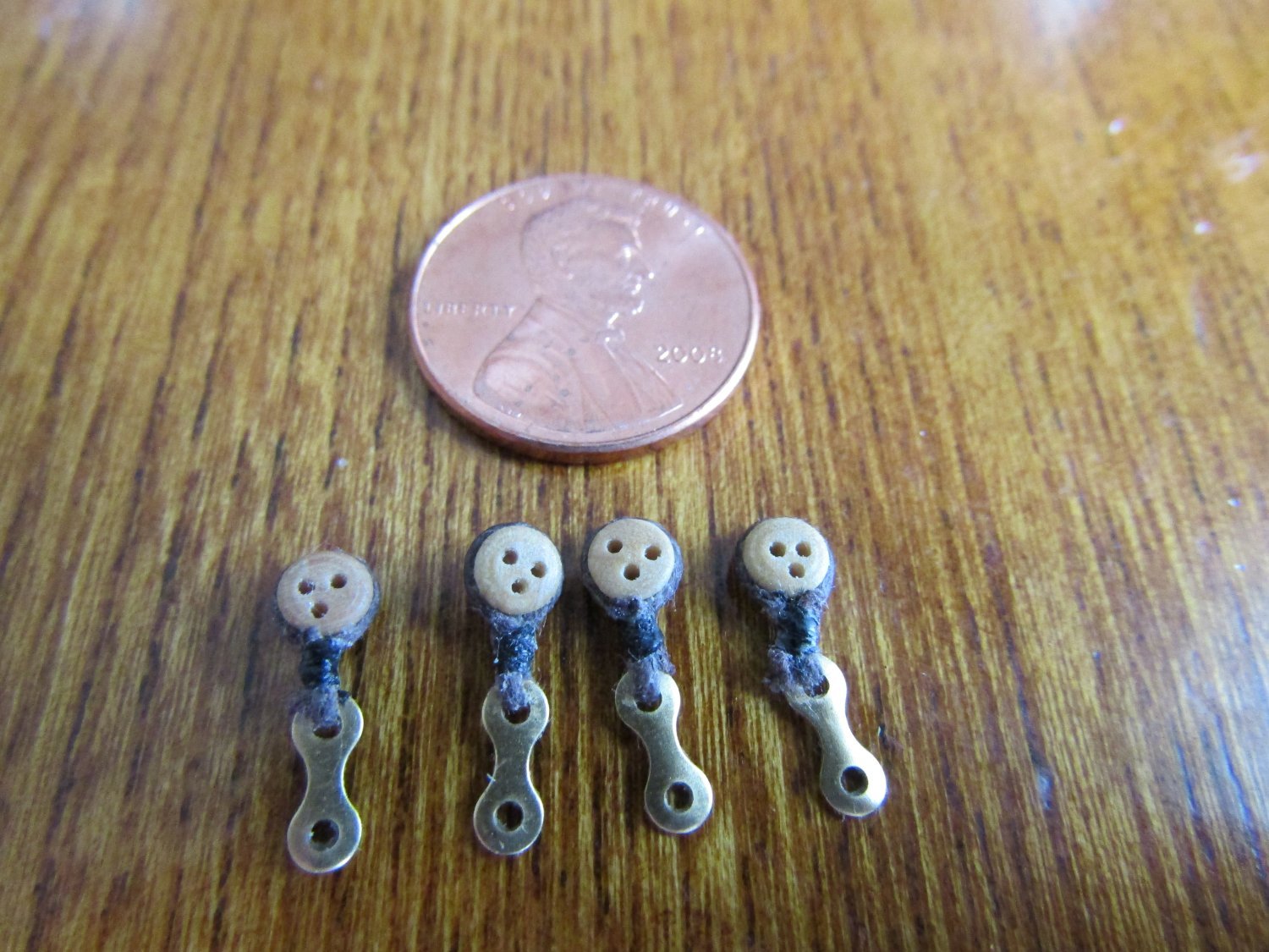
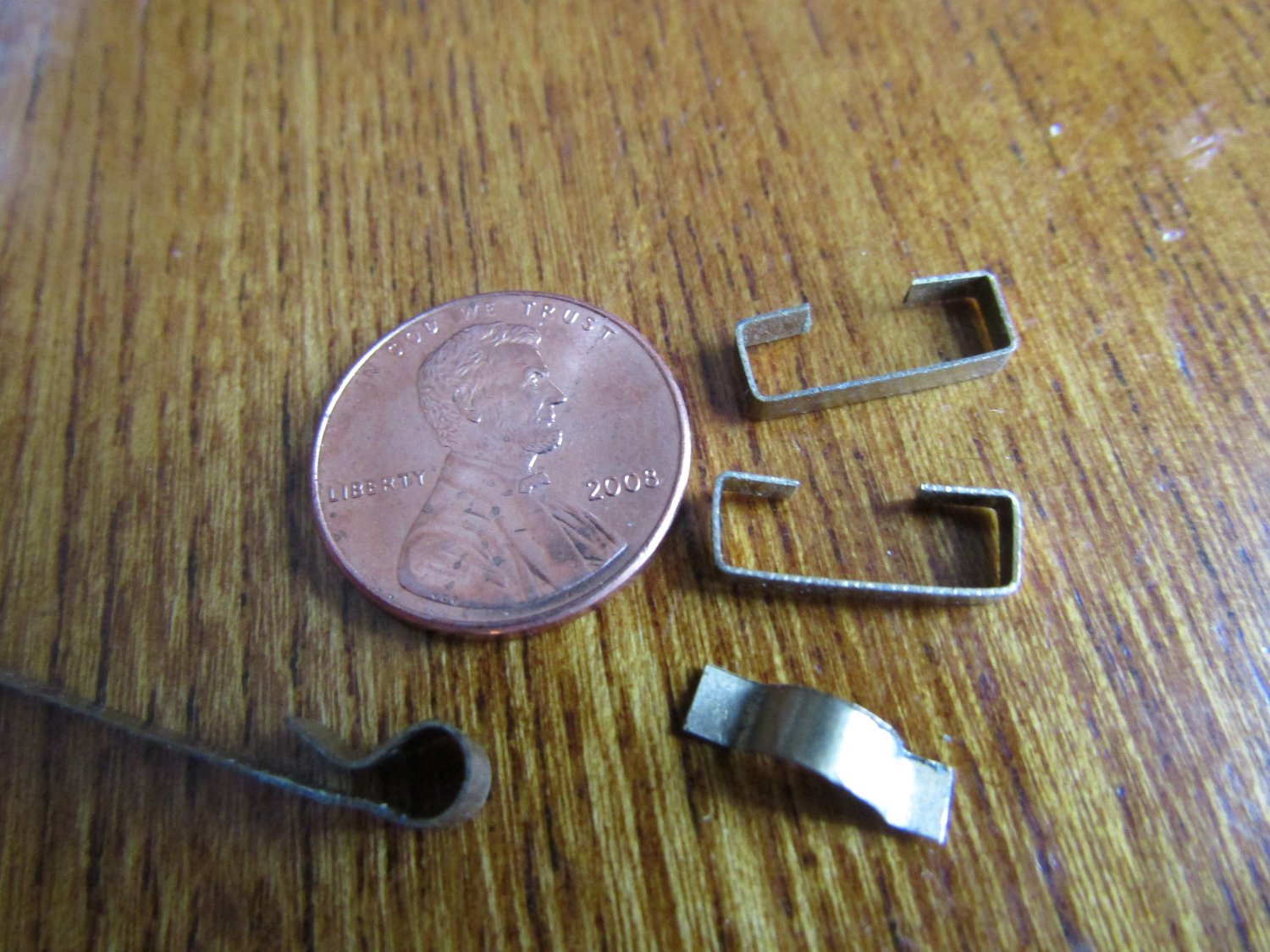
Metal work: Got the metal work done quite a while ago. Don't remember exactly when, probably during a break near the end of the hull planking or immediately after I finished it. When ever it was I wrote down some quick notes. I didn't post then so what follows is what I had in my head at that time. Between the few miniature pliers I had, the tools my son gave me from that were supplied with a "Star Wars" metal model kit he received as a gift and the loan of a couple more from the Boss's Rosery making kit she made up, I had a pretty good selection of metal working pliers to work with. I completed the metal work for the bowsprit support, mast truss and mast truss reinforcements. My first attempt at the mast truss was a complete failure. You can only bend, straighten and rebend thin brass sheet so many times before you have more pieces than you started with. I wrapped the brass strip around the mast to get the necessary curve. But trying to bend the tabs at the proper location became an exercise in futility. I spent a few hours trying to figure out how I might better accomplish this task. I remembered reading in a build log where the author used the remnants from the hull frame sheet as a guide in checking the faring of the hull. The wheels started turning and I decided to try a modified punch and die method. I took some scraps from my planking and glued them together face to face, squared them up and put the appropriate sized radius on one edge, and rounded of the sharp corners. Then I laid the brass strip across that edge. Using the appropriate section from my old mast, I pressed the brass down into the radius using a small pair of pliers. With the mast section still in place, I then bent each down to form the tabs of the truss. I didn’t turn out exactly as I had hoped (tough to hold everything in place with only two hands and the tools available) but it was much better than the first attempt. The tabs still didn’t match up with the mast support as I hoped, but it looked as though with some careful fiddling I might be able to make it happen. But the question was whether there would be enough tab surface for the truss reinforcements to secure against the mast support. I bent up one truss reinforcement to see if I just might have enough of a truss tab to make this work. Got it done without any issue, kinda' surprised myself. Gave things a test fit to see how it looked. Indeed it seemed as though I just might be able make it work after all, that is if I were super careful and very lucky bending up the second truss reinforcement. Seeing how much 3mm brass strip I had left with still the bowsprit support to bend later, I was getting very nervous about having enough material to get everything done. Especially if I failed on my second truss reinforcement. To be on the safe side I decided I should see about getting some more brass sheet. Luckly my preferred hobby supply store had the correct thickness in stock and was able to pick up a 1" x 12" piece. The metal Gods were with me, the second truss reinforcement turned out just fine. Did a dry fit and my mast was actually held in place with my completed metal work fixin's. I had just a bit of difficulty with the bowsprit support. Round things have a tendency to turn and/or roll, which is a good thing unless you don’t want them to. Finally got the bowsprit support bent and it looks just fine. I'm sure I'll know if it works when it's time to insall the bow sprit. I’m going to wait to trim it to length and drill the holes at installation. I’ll hold off on pics of the individual pieces and show them installed.
-
Welcome Glomar, I'm also a beginner still working on my first build. You are correct on both counts, the fairing of the frames/bulkheads isn't as complicated as you think and the fear you feel is real, at least it was for me. IMHO a couple of things to keep in mind, every mistake/error you make can be fixed so rest your mind there and probably most importantly is to take your time. Researching the various techniques puts you on the right path, but fully understanding the techniques is what gets you there. If you don't get it, no matter what it is, ask and somebody will step up and help you out. This community is just awesome in their knowledge and skills but probably the best at helping/teaching us rookies how its done. Everybody has their own way of doing things, I'm pretty sure none of them are wrong its just what works for them. Some people use thread to check for sufficient fairing, some use a full plank, I myself used a thick piece of card cut to plank width because it just worked for me. You do need to check every plank location, no avoiding that, but you don't have to line all the planks up at once. I would take my card and just slide it up and down the the frame/bulkhead and check good frame/bulkhead contact to plank at each location and check for any peaks and/or flats between frames. I would say the biggest pit fall is not fairing enough. During the course of planking you'll have numerous opportunities to go back (because you're always checking again and again, trust me) and hit that one spot just a little bit more if necessary. And if, just if you would happen to fair too much, you can always build it back up using some scrap wood from the kit and give it another try. Take your time, relax and enjoy the journey.
-
" . . . 99.9% of the people who see your model in the flesh won't know a rudder from an udder . . . " totally priceless
-
Allanyed, I agree completely agree with you, we definately are our own harshest critics. Prior to starting my oars I found similar info to what you provided in my copies of Historic Ship Models by Wolfram zu Mondfeld and Ship Modeling from Stem to Stern by Milton Roth. The first book mentioned had numerous examples of different oars from different eras and purposes/applications. The second book actually had an illustration of an oar used on boats the same size as my Jolly Boat and was shown at 1:24 scale (my Jolly Boat is 1:25 scale). That particular illustration showed a leather wrap which led me to wanting to do some sort of wrap on my oars.
-
Being a beginner myself, the only piece of advice I can offer is to take your time and enjoy the voyage to the best of your tolerance. Not everything is going to be as easy as it might appear nor work out exactly as one has planned. This is a hobby you really can just walk away from (that is after you've capped the glue) for a bit and regroup your thoughts and adjust your attitude as needed,
-
Thank you HHH and Kevin-the-lubber. I half figured that most people wouldn't notice the rudder (but knew eveyone here would so I just owned it up front) and hope they'll notice the better things I was able to do. I had mentioned in an earlier post about serving the knob end of the tiller but I've decided against it. Thinking about scale, right now I'm guessing the diameter is 1.5" to 2.0" and I don't feel good about it getting any bigger. But I may do some wrapping on the oars where they would normally be resting is our pseudo oarlocks. I really like the looks of a Turks Head, I think its called, but not sure if it could be differentiated with just a simple wrap. In prepping the text for this post I found another I had started regarding the metal work completion but I don't believe I ever posted it. I'll have to double check.
-
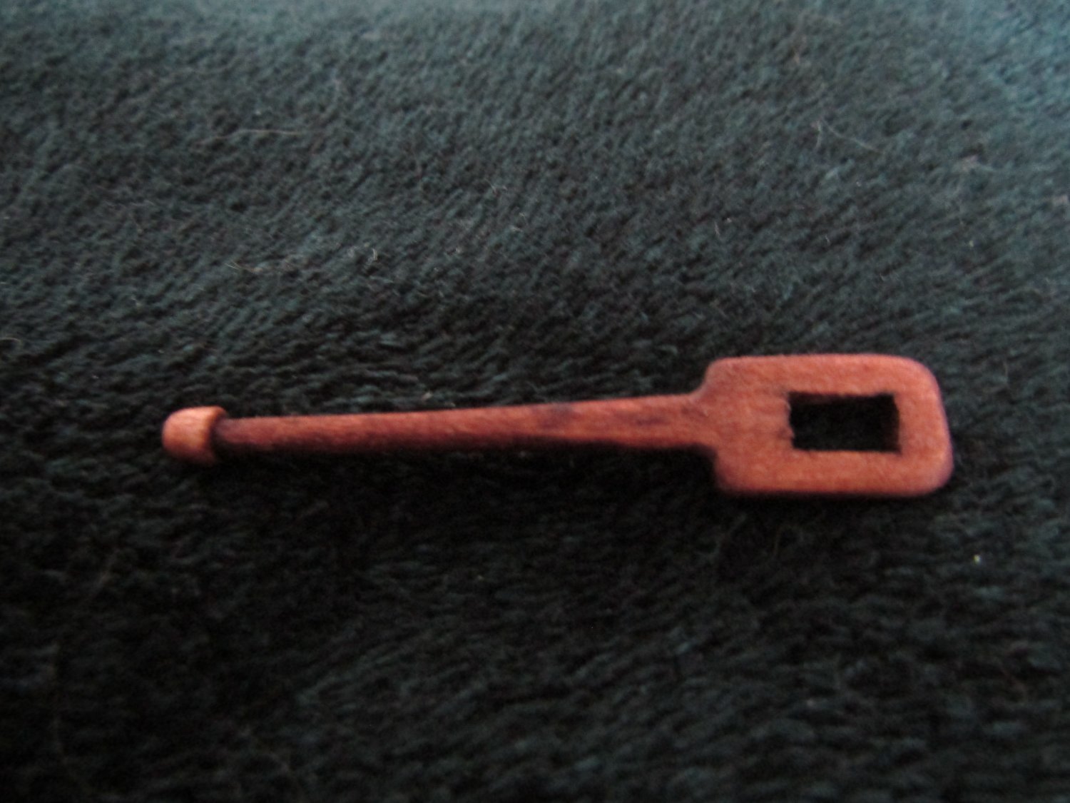
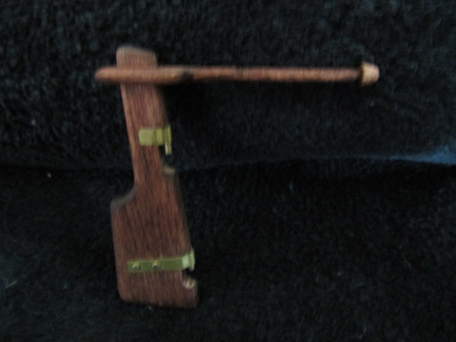
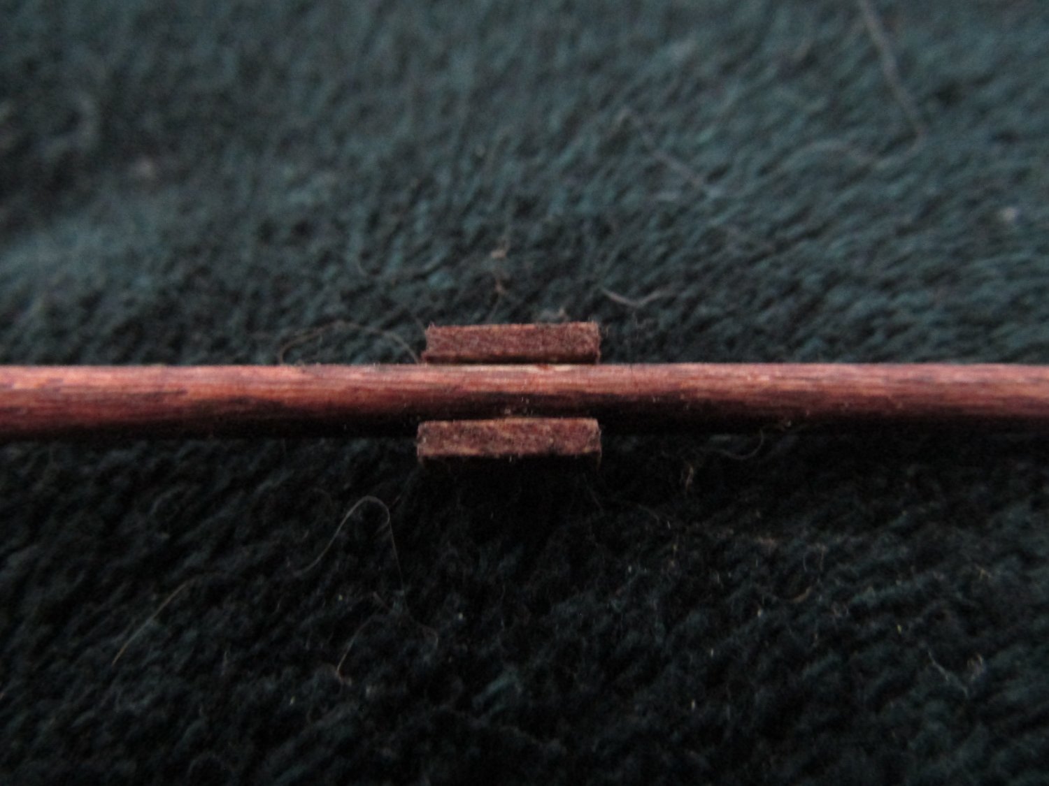
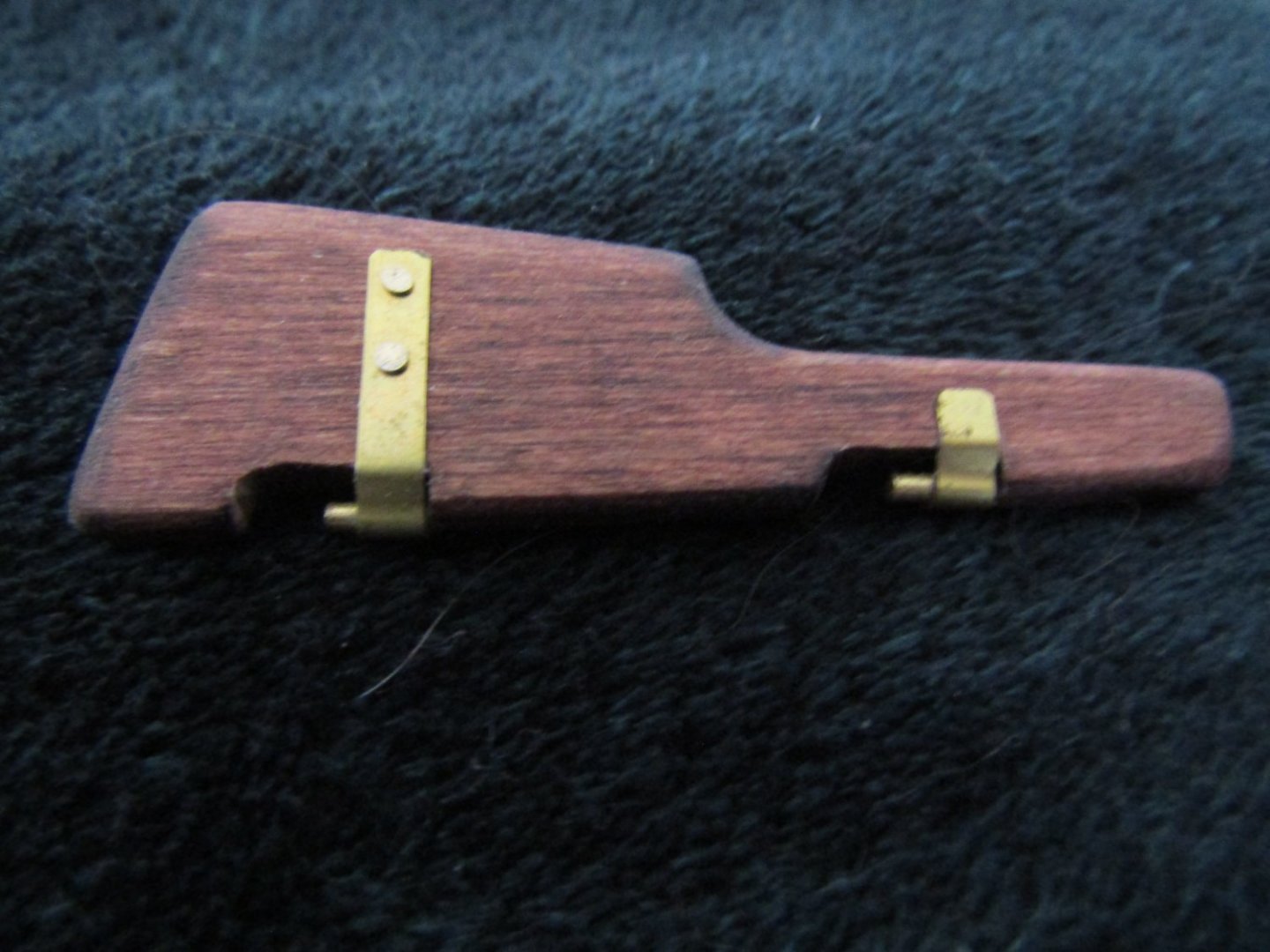
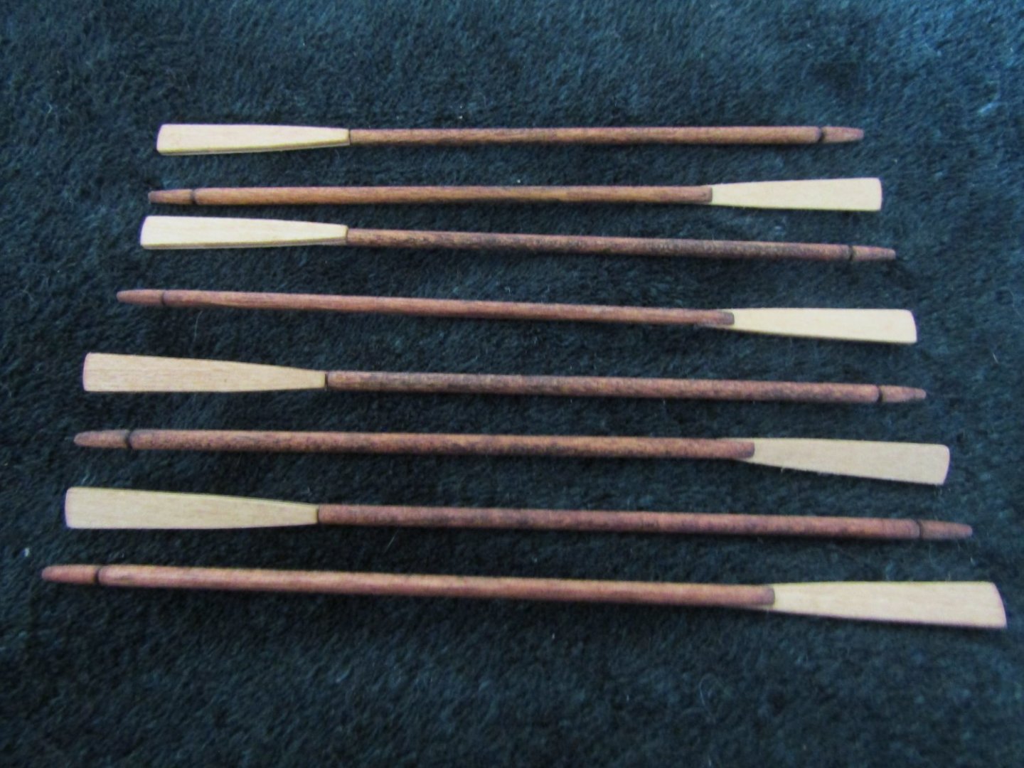
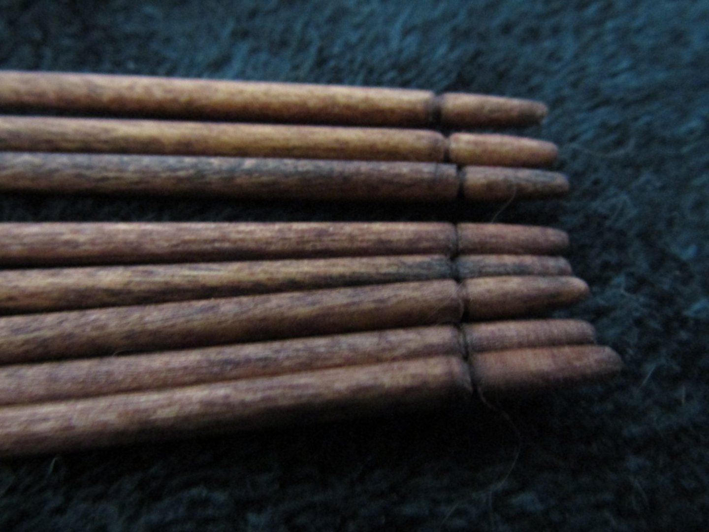
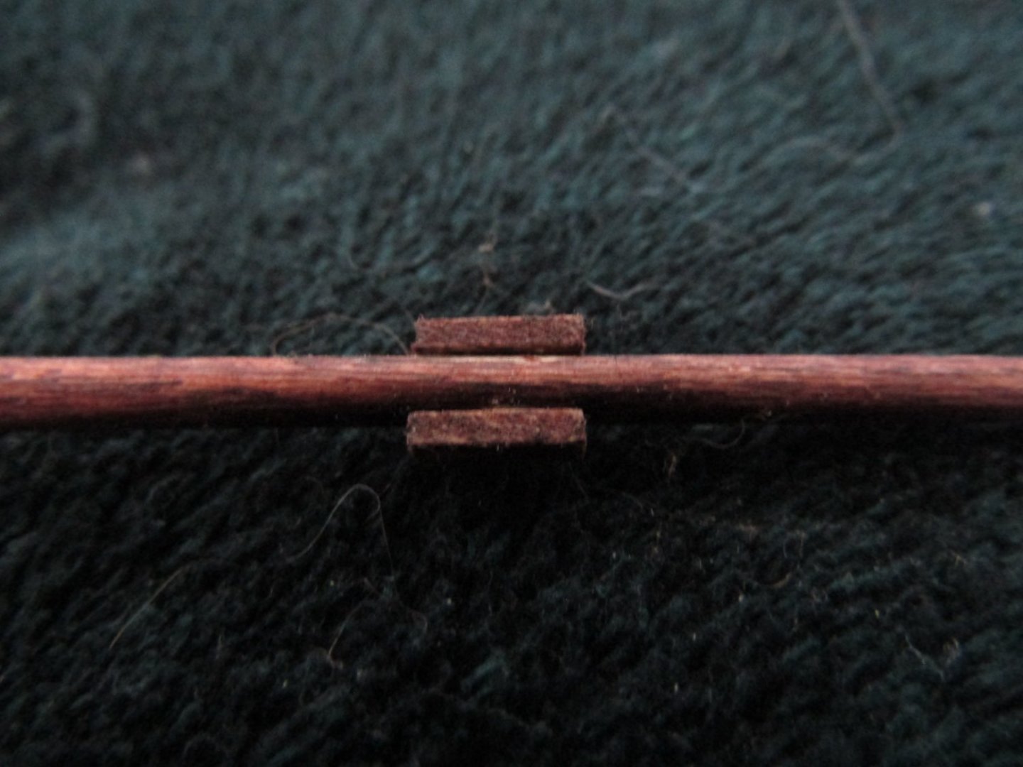
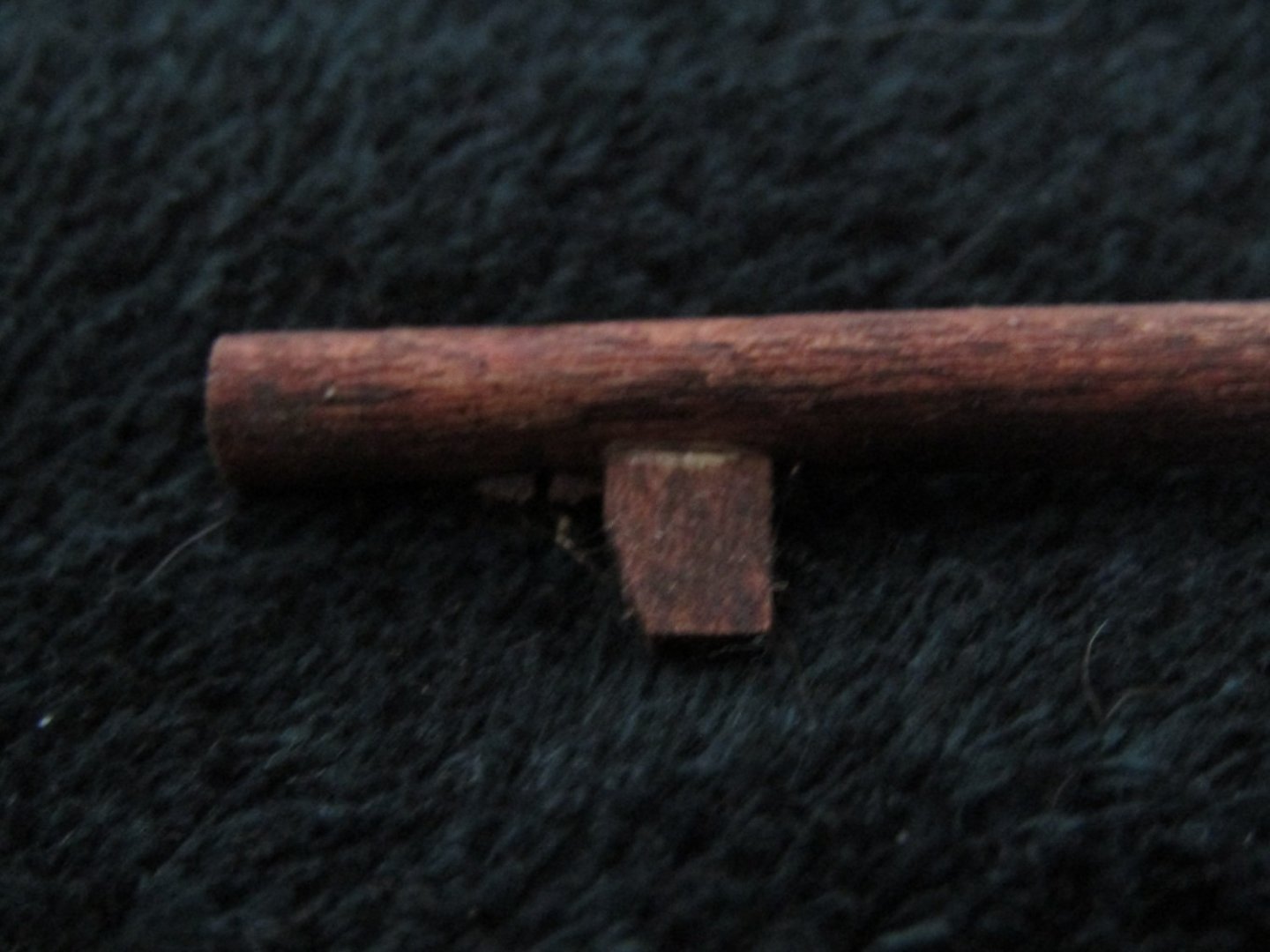
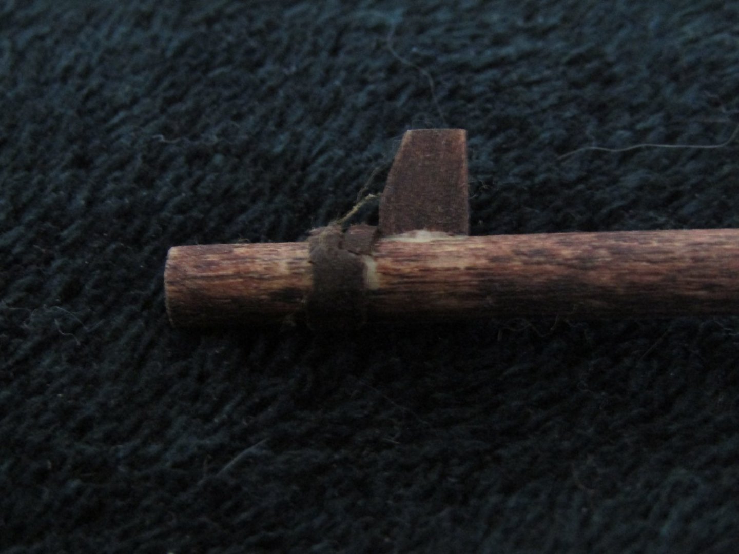
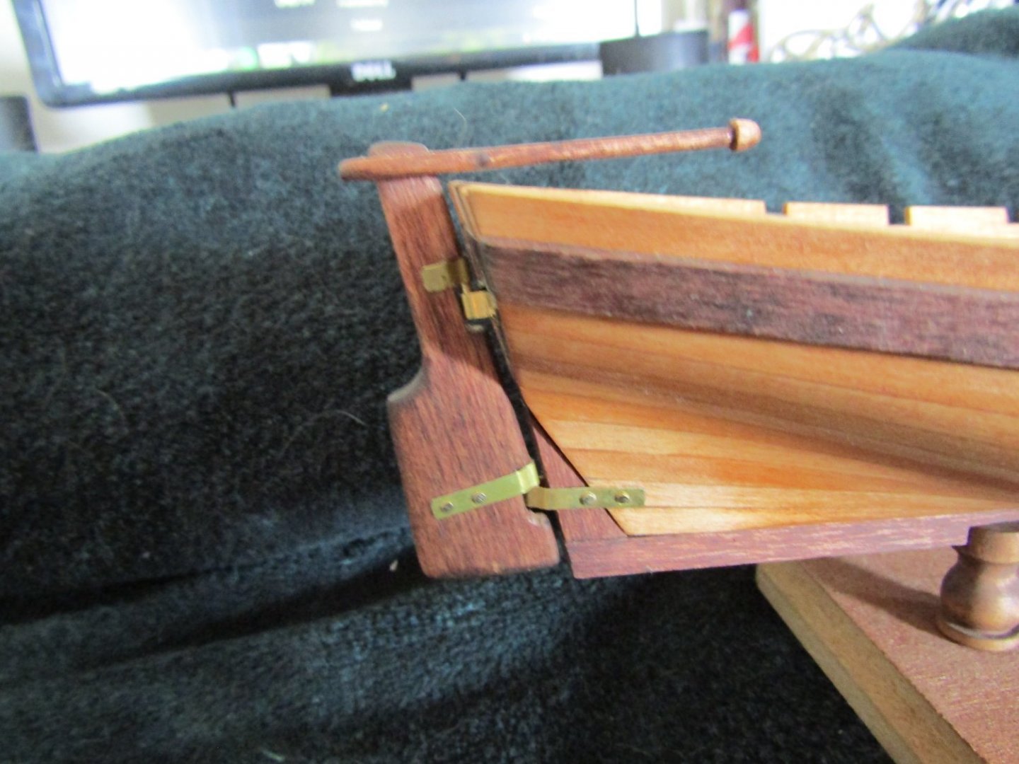
Finally struggled thru and got everything back together and holding so far. Here is the rudder showing the elongation of the slot at the pintles. Next up is the the tiller I made rather than using the brass rod as shown in the instructions. I’m saving the brass rod to make a horse to handle the boom rigging. This is a two piece assembly. The little knob at the end is a separate piece. I predrilled a hole in the flat side and followed it up to largest diameter it would take. Rounded off the corner ever so slightly. I then carved down the end of the tiller to a depth and diameter to fit into the hole. Glued it up to reassure myself my PVA was good and then stained the assembly. Yup, learned from my earlier mistakes. And the tiller on the rudder. Here are my oars, followed up by a close up of the formed handles I created. I used a triangle shaped file to create the start of the handle and sandpaper to smooth out each end. I surprised myself in being able to get them looking pretty much the same, that is if you don’t look for very long. Next is a view of the cheeks on the mast. I felt I needed to increase the mating surface of the cheeks to the mast for better adhesion. I scored a center line down the length with my xacto to serve as a guide for my triangle file. Then made a very shallow V groove. Followed that up with my round file to match the diameter of the mast. The next two show the foot of the mast with the bowsprit support in place and the “fix-it” I had to come up with to handle my mast tapering blow it. I used a file to make a small flat on the mast, again to increase mating surfaces for better adhesion. The first one shows the aft side and the second shows the bow side. That ugly looking glob just below the bowsprit support is the spacer I created to compensate for the unnecessary tapering I did. What I did was take 2 pieces from scraps of my hull planking, squared them up and glued them together. I then created a convex curve on one side to match the curve of the mast reinforcements. Then calculated how thick this spacer needed to be, in the fore and aft direction, and created a hole/curve to match the mast. I then very carefully cut the desired “C” shaped portion of the hole/curve out of the glued together boards. Then I added just a drop of glue to the mast and placed the “C” shaped piece in place. Then fitted the mast/”C” shaped piece into the curve of the mast reinforcements using the already made metal work and let it sit over night. I was quite pleased to see that I was able to remove the mast from the reinforcement piece and the “C” shaped piece came with it. And that leaves us with the last picture with everything in place at this point of my build. There isn’t a blanket big enough to cover up the elephant in the room. As is readily seen, I really messed up the attachment of the bottom gudgeon. It is so disappointing to have worked/struggled so much fixing, re-fixing and re-re-fixing my mistakes to have this as a result. I knew the leading edge of the rudder needed to be parallel to the transom, the bottom of the rudder is to be even with the keel and the bottom gudgeon needed to be parallel with the pintle. I was able to get everything positioned as needed and used a finger clamp on the rudder keeping everything in place, or so I thought. I marked the aft holes to be drilled then the forward holes. Some how, some way, some time during this process the gudgeon obviously shifted. I removed the rudder and gudgeon so I could drill the holes for the nails. Was able to get all four holes to sufficient depth without breaking through or breaking the drill bit, I was so relieved. Using CA I got the gudgeon and nails installed and gave it a look. Something didn’t look right. It wasn’t until I got the rudder to within 6 inches of the boat that I saw my error and was so angry with myself for making such a mistake, I just couldn’t believe it. At this point I believe I’m just going to eat it and let it be. I’m sure some day, after I’ve looked at it for far too long, I’ll consider looking to fixing it . . . . again.


- 129 replies
-
- 5
-
-
- Bounty Jolly Boat
- Artesania Latina
- (and 1 more)
-
Kevin-the-lubber, actually didn't need to do the "S" grooves it turns out. When I disassembled by dry fit, the transome post had come free of the transome but the keel pieces and the transome post to the keel were all firmly attached to my great suprise!!!!! I decided to just put it all back together using CA because of the brass. I figured that with the gudgeon nails attached to the transom post at the aft end and on the hull planking on the other end there was no way the transome post was going anywhere. Thank you for your comments on my hull planking, it is greatly appreciated. Being such the novice that I am, drop planks and steelers still look very challenging in being able to execute the joints correctly. Some of the more complex builds I've read still perplex me in that some locations appear to violate the "no less than half plank width" rule. Guess I'll figure it out when I get there. Saving my last little piece of brass to make my horse for the boom rigging, I've made the tiller for the rudder from scratch and have the stained assembly drying (did all the glueing required prior to staining ha-ha, believe it or not I can learn from my FUBARS). Then a bit of serving, just for looks, at the hand end and its done.
- 129 replies
-
- 1
-
-
- Bounty Jolly Boat
- Artesania Latina
- (and 1 more)
-
Ken_2, thank you so much for the visit to my build log and your kind comments, they are greatly appreciated. To be honest, I am rather pleased how my hull planking turned out, granted it took me a couple tries and had to purchase more planking material to get it done. I wound up using bits and pieces of many techniques that I researched and of those offered to me. I'm sure your hull planking will turn out great, just take your time. I can't express how much it means to me that someone finds my build log helpful. It is very humbling to actually make a positive contribution while in the company of so many great builders. If at any time I can offer an opinion, please don't hesitate to ask. I visited your build log and will be following along. Spoiler Alert: I now have my keel, transome post and bottom gudgeon attached with a removable rudder. PVA is drying on my removable tiller with just a little more work to do before I consider that task completed. Will post pics when it is done. kev
- 129 replies
-
- 1
-

-
- Bounty Jolly Boat
- Artesania Latina
- (and 1 more)
-
Welcome to the Jolly Boat club. Hope you don't mind me pulling up a chair and following along. I'm very curious to see if you run across any of the same issues I had and if so, how you deal with them. I attached my deck boards at this point and later wished I hadn't because they hindered clamping surface availability during the hull planking and kept popping off (maybe I'm just ham-fisted). With this being an open boat there is plenty of accessibility in order to attach the deck boards after the hull planking is complete. Good luck and have fun. kev
-
thanks for the info
-
That makes perfect sense and I have a follow up question. So what about the horseshoe shape? What does it signify and why that shape?
-
Kevin-the-lubber, thank you for stopping by and taking an interest in my build. To answer your questions: no the PVA doesn't peel off, it sets up hard just as the first time it was used and yes my stain is oil based. The stain was purchased very early in my build long before I learned that water based stain is what should be used for this very reason. I've been able to remove the PVA by scraping it off with the edge of my hobby knife. It kinda' dusts off or flakes off in larger pieces. This tells me the PVA isn't penetrating the wood and the only reason I can think of is the oil based stain barrier. As stated earlier, I can't drill a perpendicular hole to save my life so I'm not considering the dowel method you suggest, it just isn't within my skill set. I can't even use my pin vise for the predrilling I did for the gudgeon nails. I got some painters tape and wrapped the shank portion of the drill bit a few times, for better "grip", and turned the bit between my fingers to help prevent the bit from snapping in two. I've recieved another confirmation that my serpentine goove isn't really a bad idea, so I'm going to give it a shot. Thanks again for your visit to my build log, your sympathy of my problem and suggestions are greatly appreciated. And your positive comment of the appearance of my little Jolly Boat is very encouraging. kev
- 129 replies
-
- 2
-
-
- Bounty Jolly Boat
- Artesania Latina
- (and 1 more)