HOLIDAY DONATION DRIVE - SUPPORT MSW - DO YOUR PART TO KEEP THIS GREAT FORUM GOING!
×


Dan Vadas
-
Posts
3,261 -
Joined
-
Last visited
Content Type
Profiles
Forums
Gallery
Events
Everything posted by Dan Vadas
-
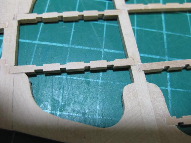
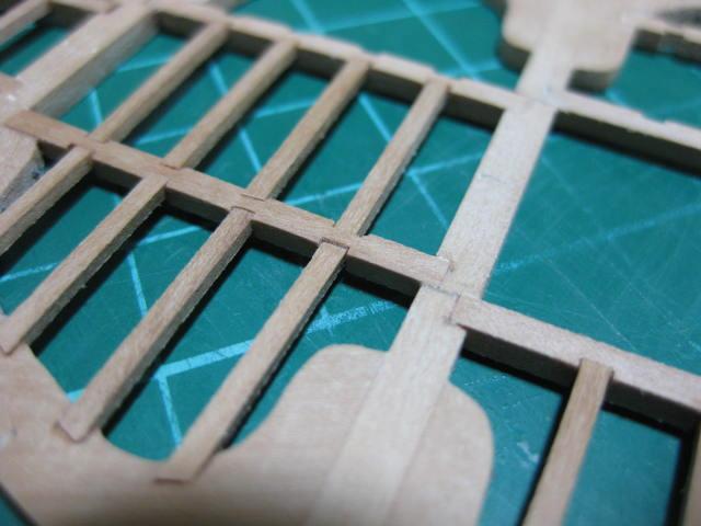
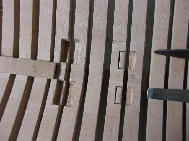
Aft Platform Carlings and Ledges The Ledge mortices in the Carlings were marked and cut into a length of (scale) 4" x 3" stock. This method worked OK for the Platforms, but came back to bite me when I tried the same technique on the Lower Deck later on. The Carlings were also morticed into the Beams : The Ledge mortices in the Lodging Knees were cut in with a narrowed Xacto chisel blade and the 3" x 2" Ledges were glued in :

-
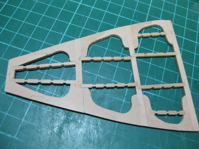
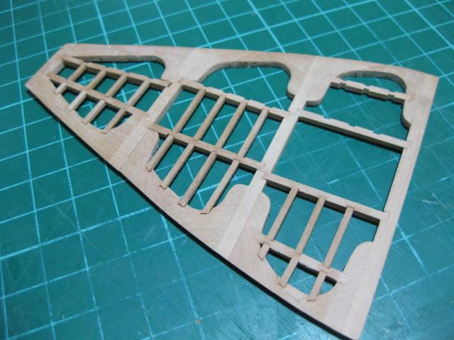
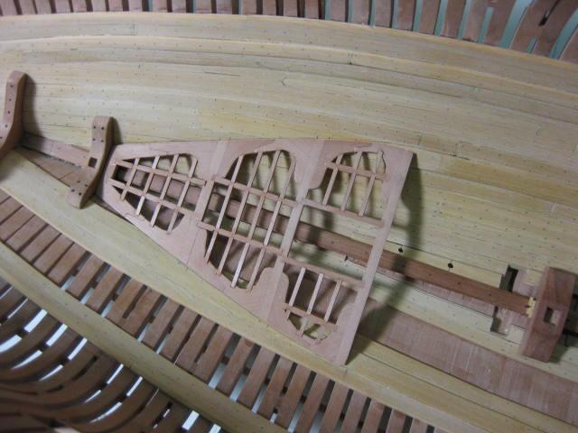
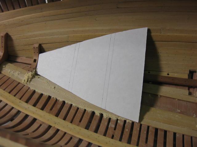
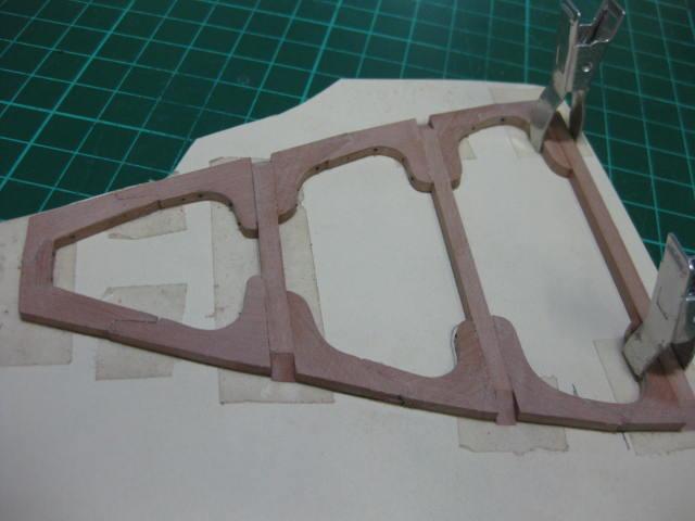
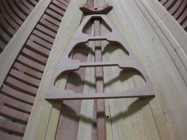
Aft Platform A card template was used to get the shape of the hull at the height of the Aft Platform : The Beams were cut and tapered at their extremities to follow the angle of the planking. Lodging Knees were traced from the diagram in TFFM and modified to suit the actual shape of the hull. The assembly was glued together : Then the outer edges of the knees were sanded fair :
-
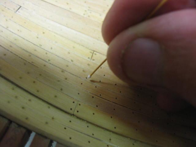
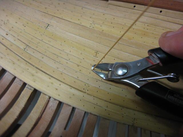
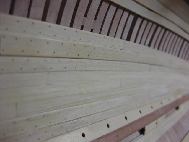
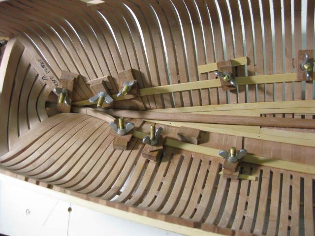
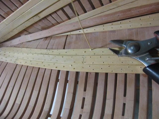
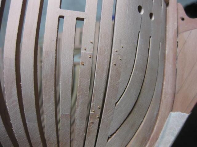
Internal Treenailing Bamboo Treenails are inserted to each frame. The Butts of the internal planking fall on different frames than the external planks for added strength.
-
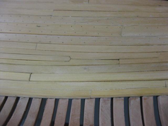
Footwaling Footwaling is the "normal" timbers between the Deck Clamps and Thickstuff. It is 2" thick. Drop Planks are used in various locations to allow for the narrowing of the planks :
-
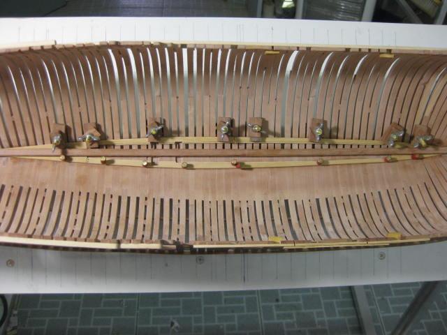
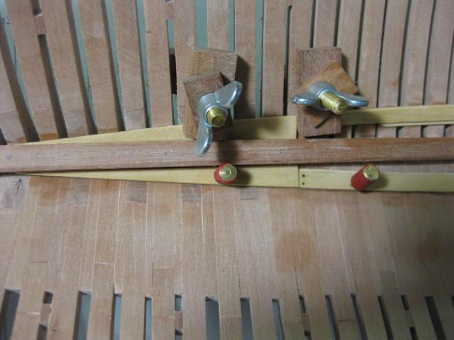
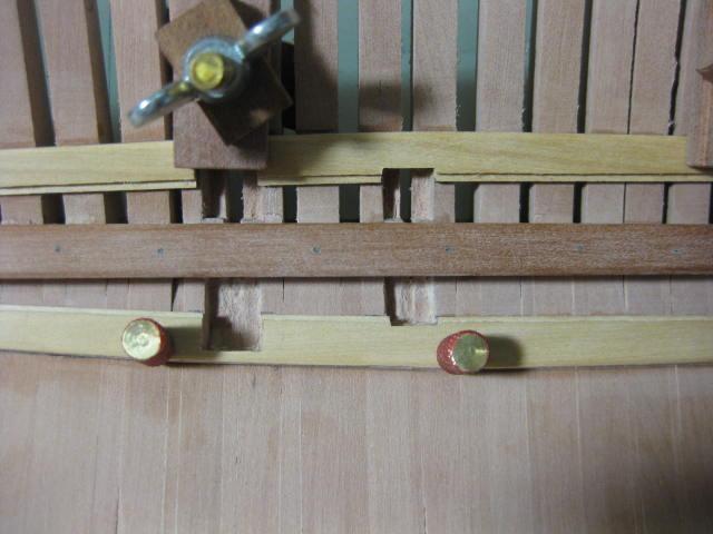
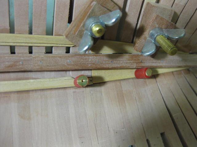
Lower Deck Clamps Deck Clamps bolt to the hull through each frame and support the Deck Beams. There are two of them each side, an upper and a lower. They are "worked" in "Top and Butt" fashion (also sometimes known as "Anchor Stock planking"). They are quite substantial boards - 4" thick at the top and tapering to 3" thick at the bottom of the lower strake. The top edges of the strakes are parallel to the waterline athwartships. Correct placement of these is crucial. I used my internal height gauge to mark their positions from the plans. The foremost end of the lower strake is cut for a Drop Plank :

-
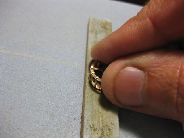
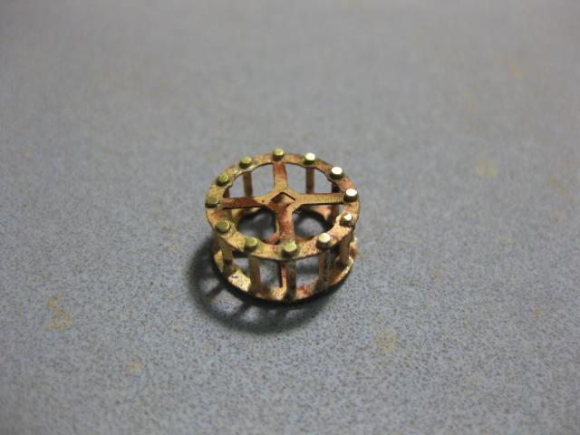
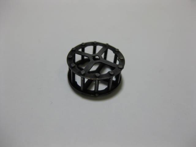
Chain Pump Sprocket Whilst I was "in the groove" with my hew-found Silver Soldering skills I thought I would make a Chain Pump Sprocket. I only need one of these as the other will be hidden from view under the Cistern. This was made in similar fashion to the Pump Inlets using the PE side parts and 0.8mm brass wire for the bolts :


-
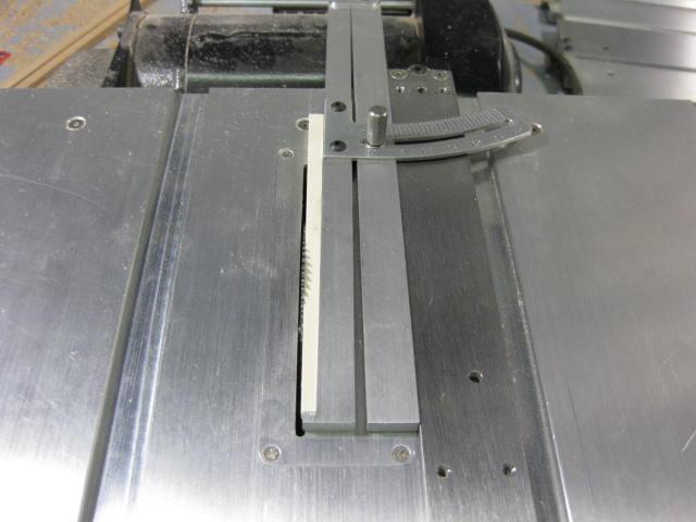
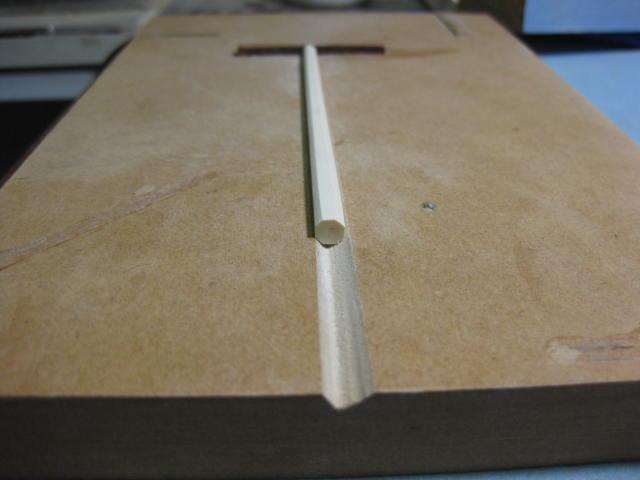
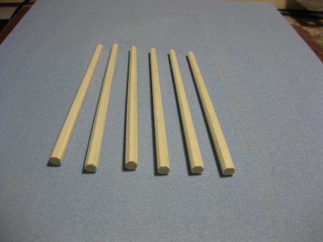
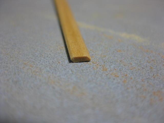
Pump Tubes The Pump Tubes are Octagonal in shape, and taper from top to bottom. I made these from Holly and cut the tapers on the Byrnes saw using the Taper Jig : Then I sanded the octagonal shape into them using a sanding block and a simple jig to hold them :

-
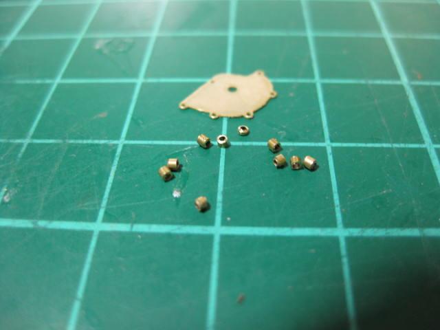
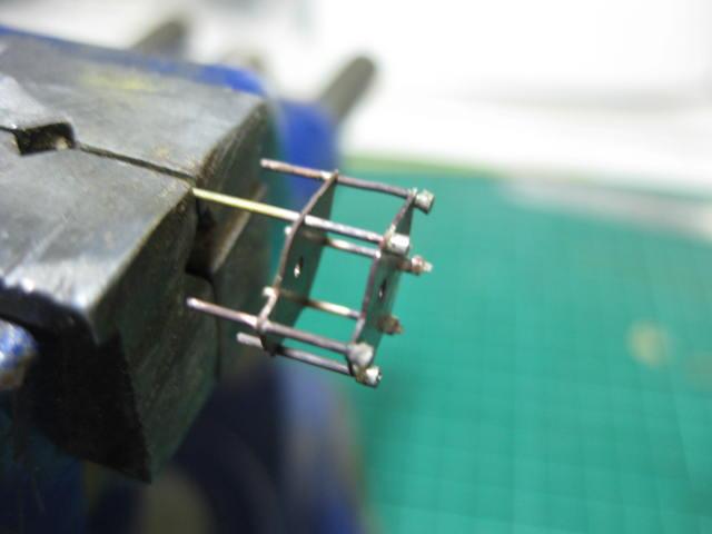
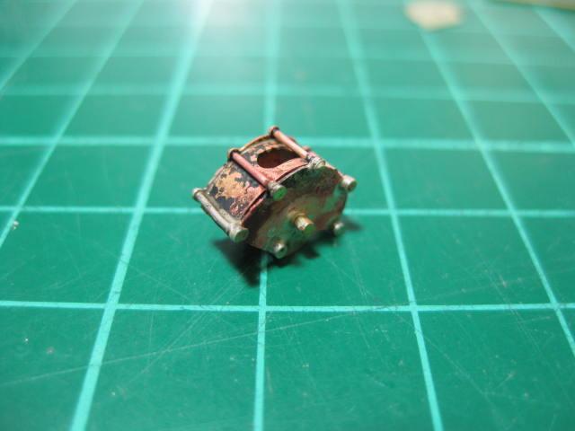
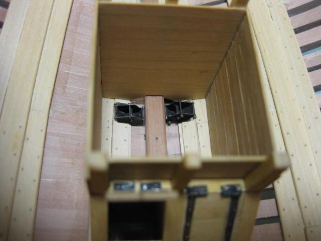
Chain Pump Inlets The Chain Pump Tubes sit in "Cast Iron" Inlets in the bottom of the well. I made the sides of these from the Photo-Etched parts supplied by Admiralty Models. I also made the bottoms from thin sheet brass, as none came with the PE set. These had to be drilled and filed : To simulate the nuts I used 0.8mm brass tubing cut into pieces with an Xacto knife. I first inserted a 0.5mm drill into the tubing to prevent it from crushing and rolled the tubing under the knife blade until it cut through : This was my first attempt at Silver Soldering, and I was very happy with the way it turned out . I used medium temperature Silver Solder Paste and a small Butane torch, about the size of a thick pen. I held the assembly in my vise while performing the operation : One of the Inlets after it was soldered and not yet cleaned up : After a pickling bath in vinegar to remove the scale and flux the part was cleaned again in Acetone and Blackened with Birchwood-Casey Brass Black diluted 1:8 with water : The Inlets in position in the well. They will completely disappear from view later, but are a good base for the Tubes to sit into :


-
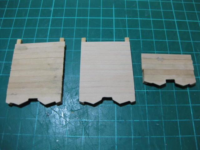
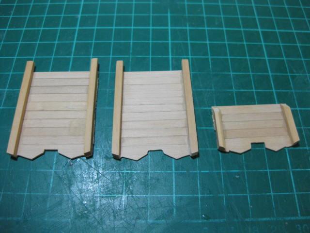
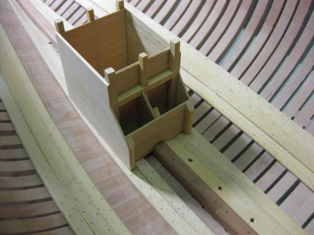
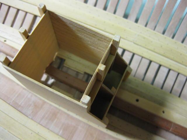
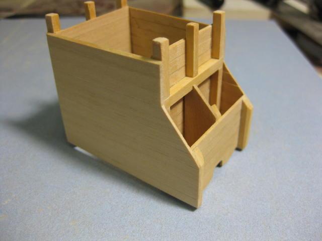
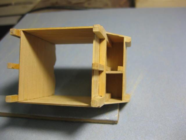
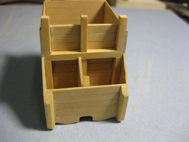
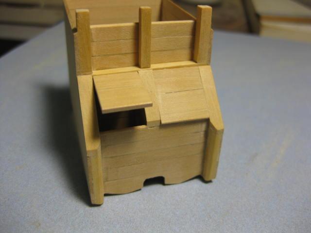
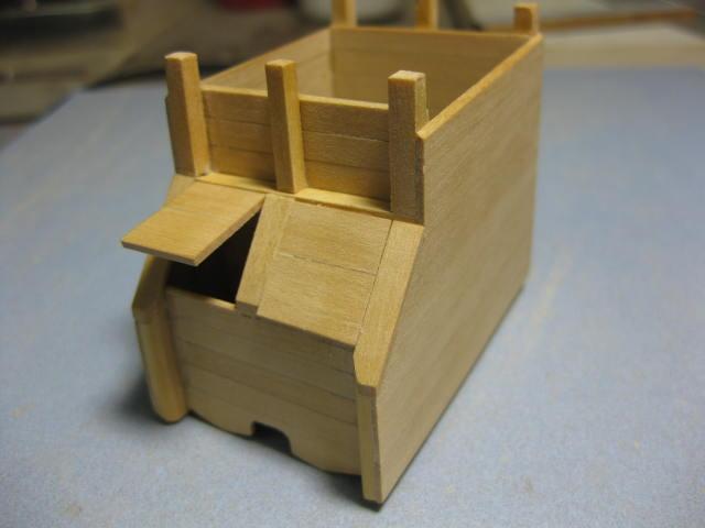
Lower Well and Shot Locker The Well contains the lower ends of the Pump Tubes and prevents any cargo from damaging or blocking them. Construction started by making card templates of the lower boards. Corner braces were cut to oversize lengths and the planks were glued to them. The edges of these were sanded flush after the glue dried : Much dry-fitting was needed to get the well to sit flush with the various timbers under it : The Shot Locker is a part of the forward end of the well : Lids were made and glued on. I'm adding the hinges etc later :

-
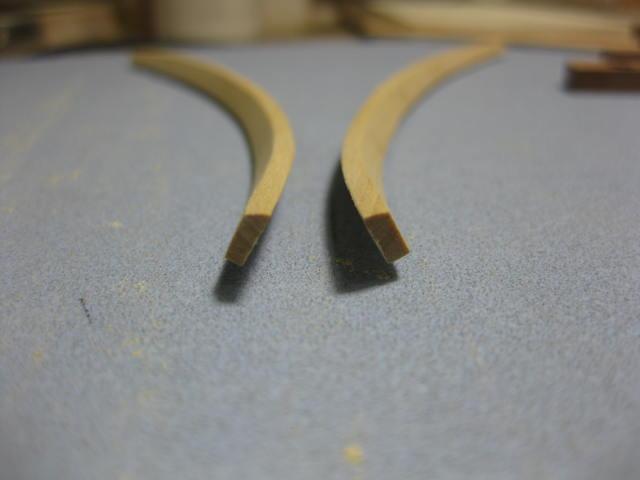
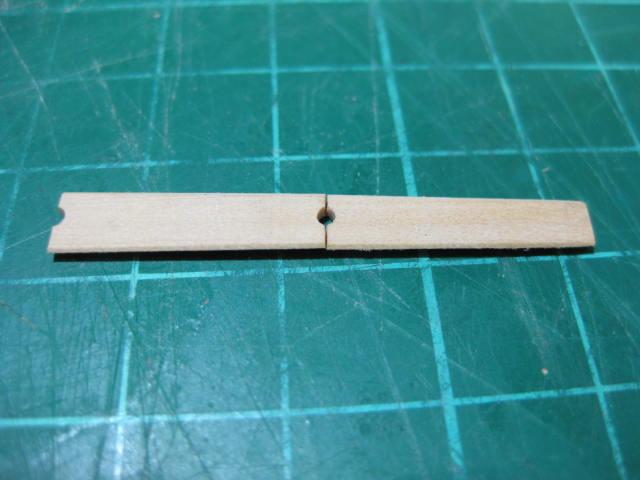
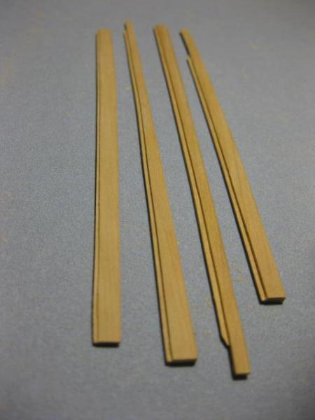
Limber Boards Limber Boards cover the channels to prevent them from being blocked. They are bevelled on each edge to fit the rebates in the limber strakes : Each board has a different width and taper to follow the line of the strakes. There are semi-circular holes at each end to enable them to be lifted out to clean the channels of debris : I am fitting all of them to the port side, but only a few to starboard to show the channels : The limber boards sit on about a 45 degree angle :

-
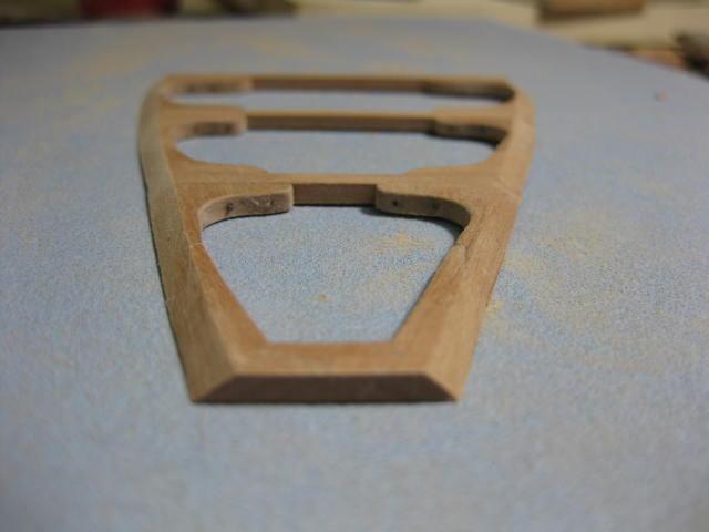
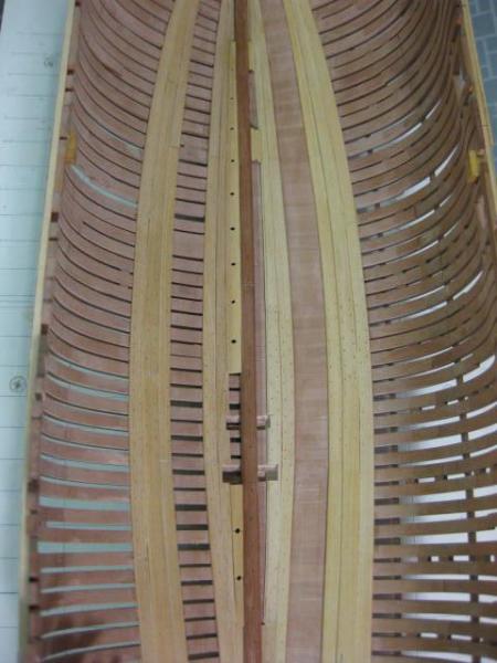
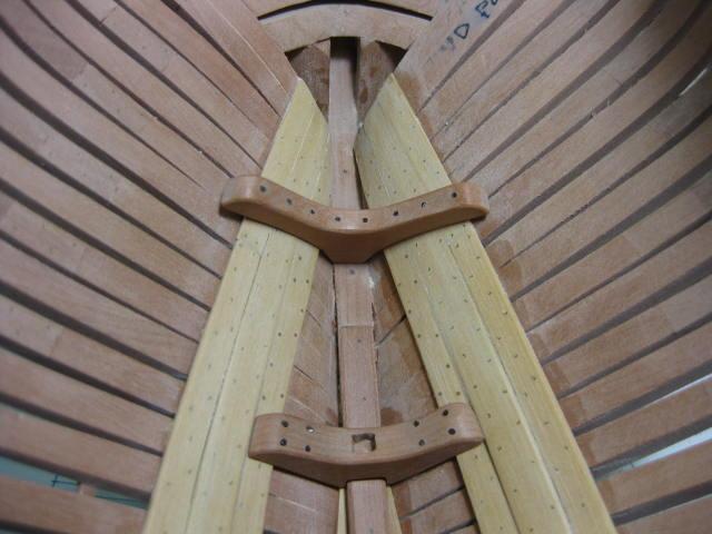
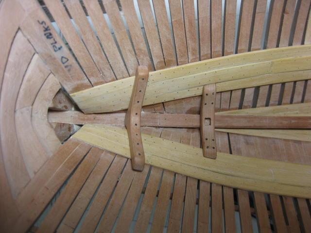
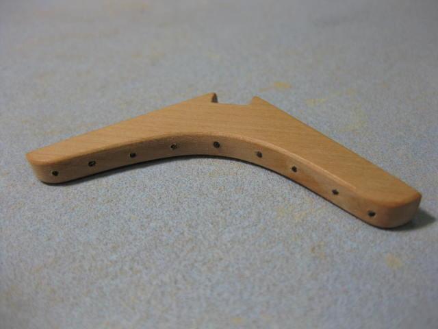
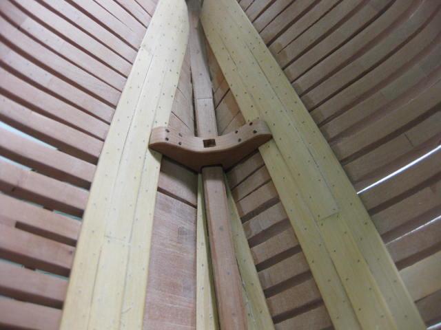
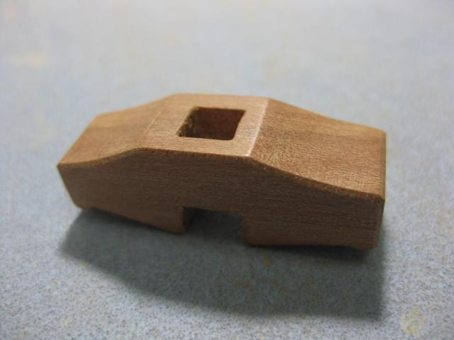
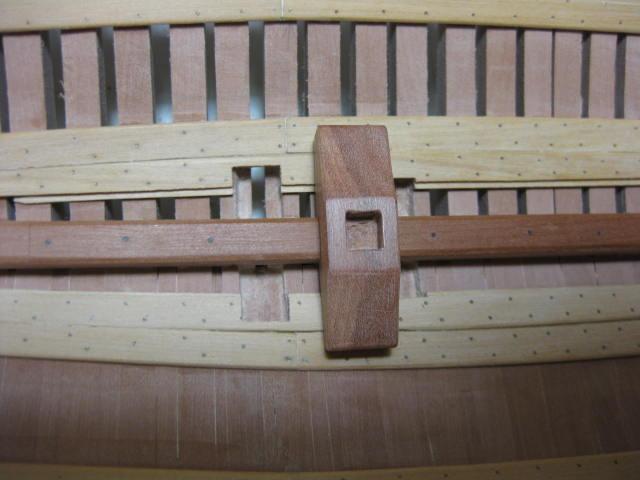
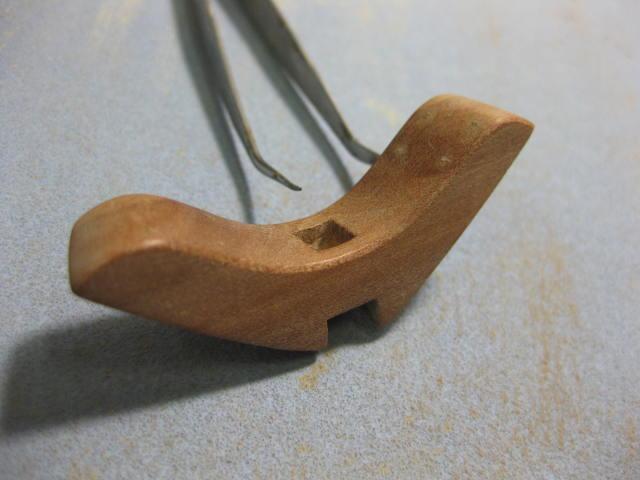
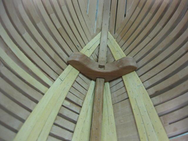
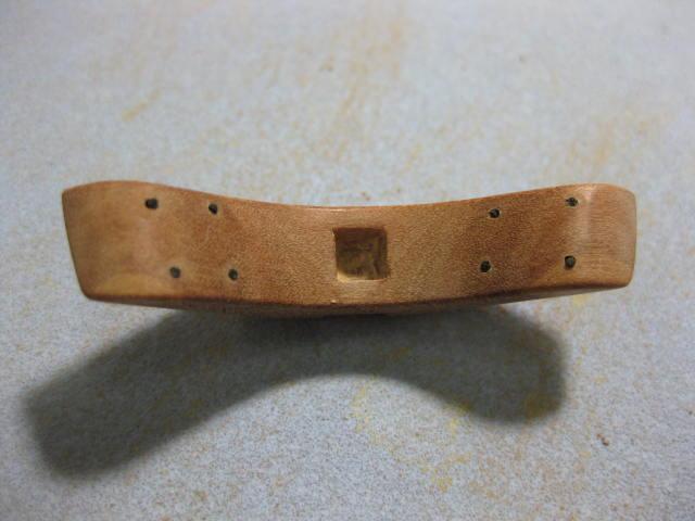
Aft Crutch and Lower Breasthook As I did with the Mast Steps, I used Cherry Ballart again for the Crutch and Breasthook. Card templates were used to transfer the shape of the hull to the undersides, and the top sides were taken from the patterns in TFFM. These two pics are the Aft Crutch : Blackened Brass wire bolts again : The Lower Breasthook in the bow :

-
Mast Steps The Mast Steps are made from Australian Cherry Ballart, as it was the only timber I had that was thick enough for the job. The color contrasts nicely with the Swiss Pear used for the frames. This is the Main Mast Step : The Foremast Step, a very tricky part to shape : Blackened Brass wire was used to simulate the bolts :
-
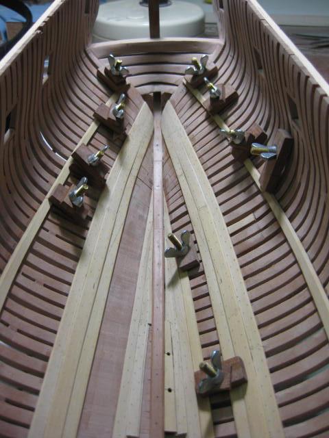
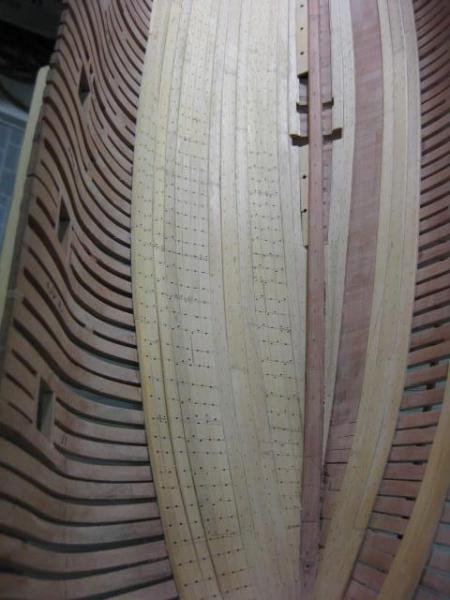
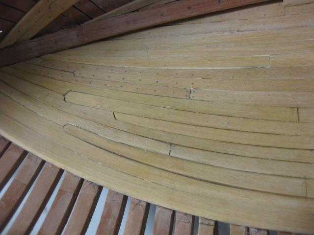
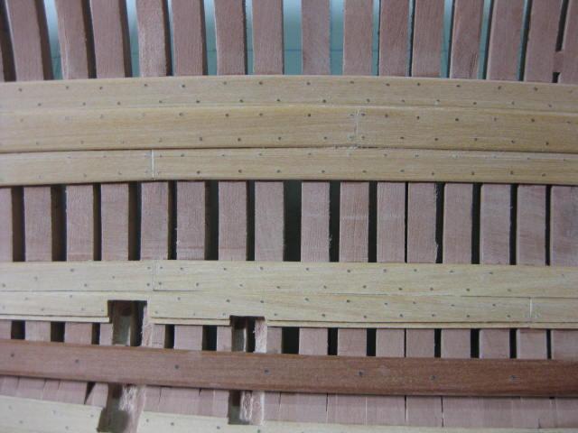
Floorhead Thickstuff and Treenails Next planks are the Floorhead Thickstuff - three planks thicker than the regular Ceiling planks. The innermost and outermost are a scale 3" thick, while the middle one is 4 1/2" thick. The Thickstuff is treenailed using bamboo.


-
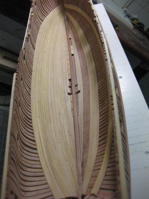
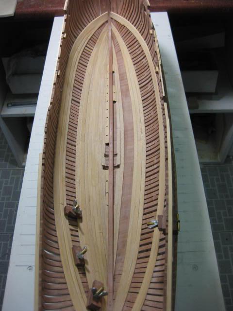
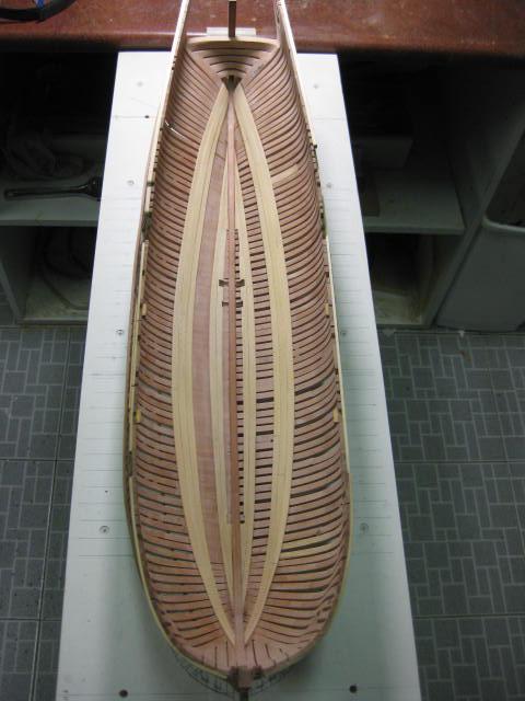
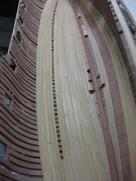
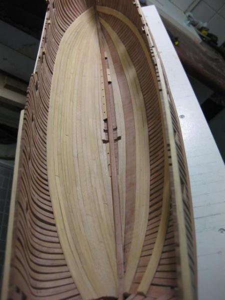
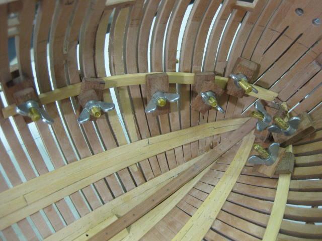
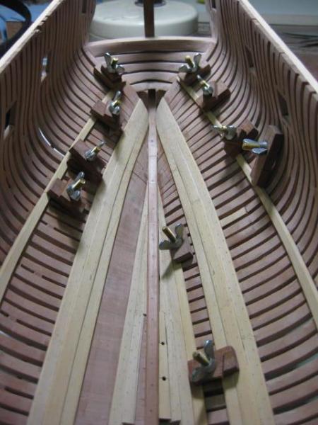
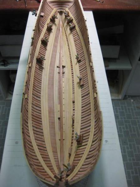
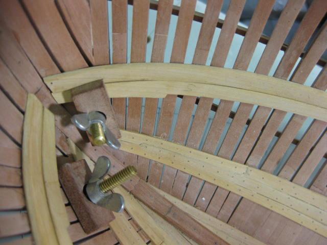
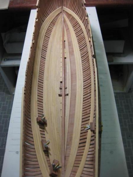
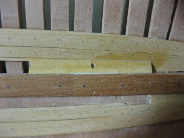
Limber Strakes The first planking to be done on the inside of the hull is the Limber Strakes. There are two "runs" of these each side, consisting of two Inner Limber Strakes and three Outer ones per side. The innermost edges of the Inner Strakes are rebated to accept the Limber Boards. The Inner Strakes are finished off with wedge shaped pieces of planking both Fore and Aft : The Pump Intake Recesses continue into the limber strakes : The Outer Limber Strakes are now fitted :
-
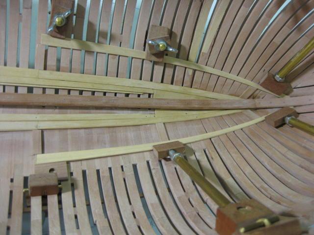
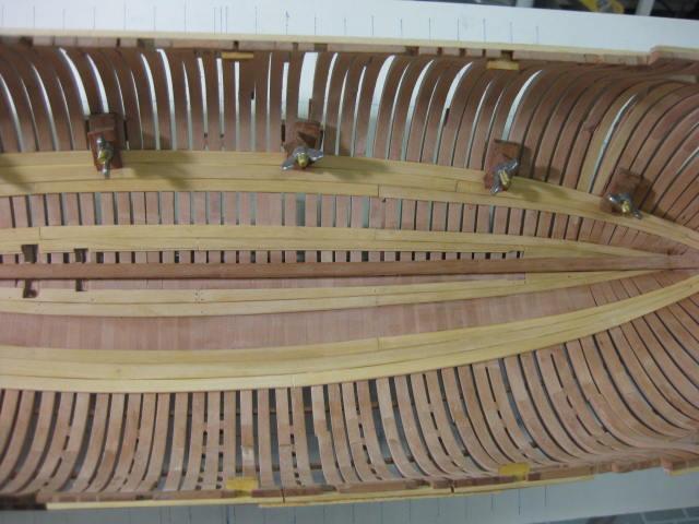
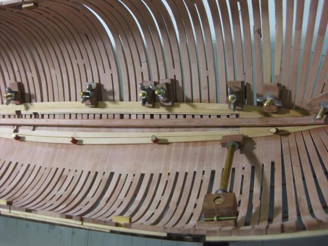
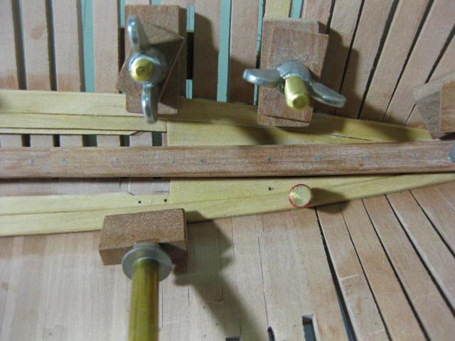
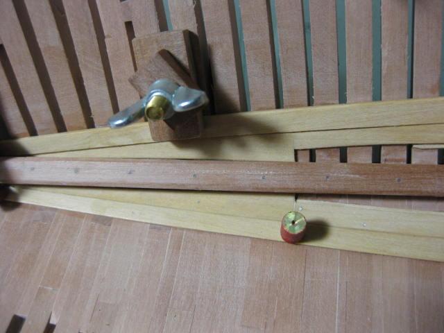
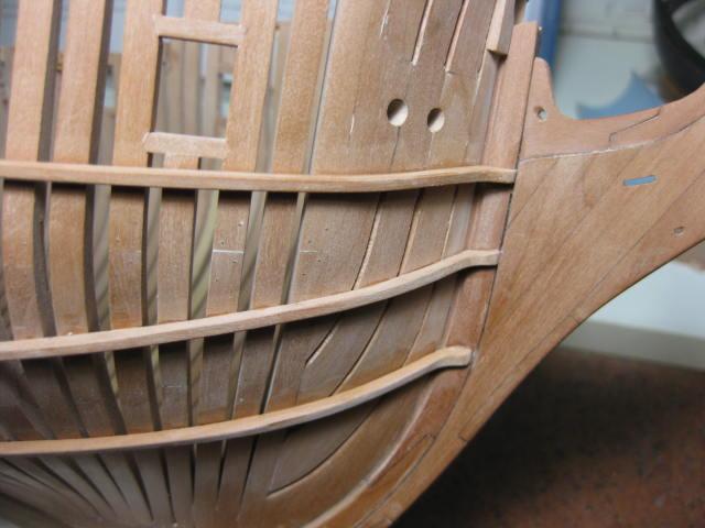
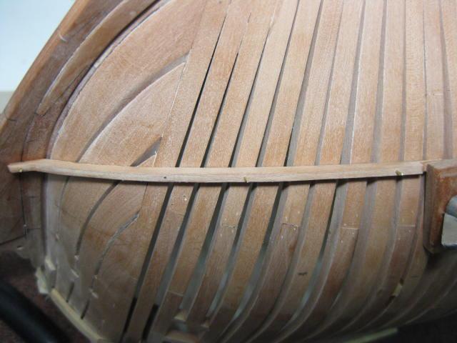
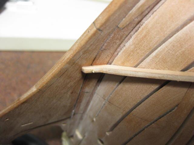
Ribbands The Ribbands are a continuation of the Harpins and run the full length of the hull. They are approximately 30 feet long and are scarf-jointed together. There were five of them on the real ship, but I am only fitting three as there will be some planking added to the mainly open Starboard side. Nails will be added later in the build - one through each frame.

-
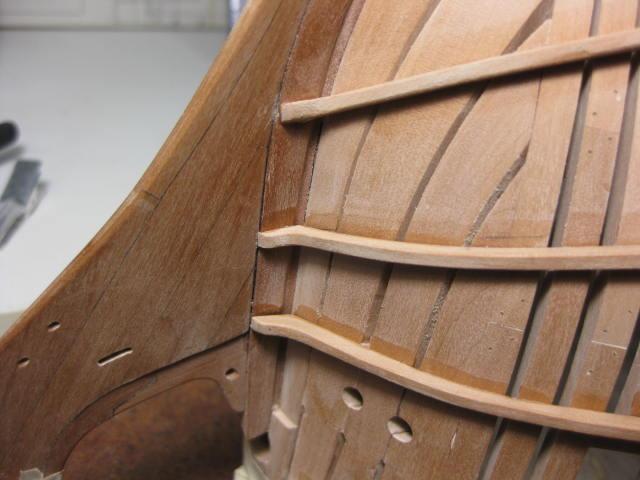
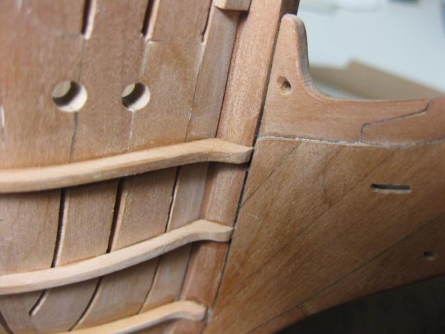
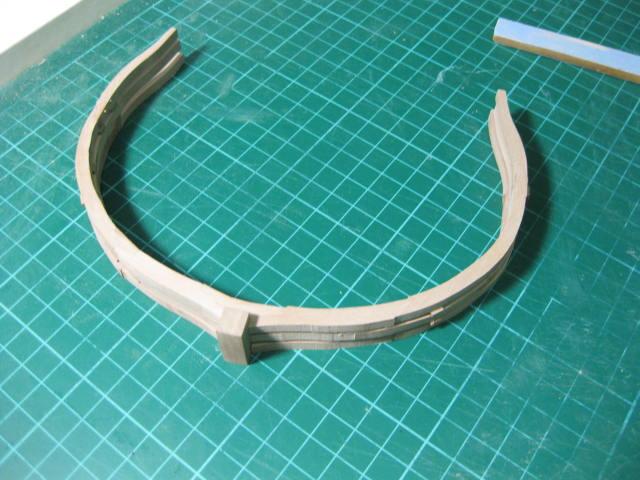
Harpins The Harpins and Ribbands were temporary Strakes used to hold the frames in position before the planking was fitted. They were progressively removed as construction continued on the real ship. The Harpins were sawn from wide timbers to accommodate the shape of the hull at the bow. They have a "toe" where they are nailed to the stem :

-
Fillings The Fillings fill the gaps between frames in the lower part of the hold to strengthen the lower part of the frames and facilitate drainage. They have varying thicknesses depending on the spacing between frames. I only fitted the Fillings to the open Starboard side, as the Port side will be covered completely - this was a BAD mistake. I took the hull off the building board for this step. When I'd finished fitting all the fillings I attempted to remount the hull on the board, but it wouldn't fit . See the whole story HERE . The Fillings were Faired in similar fashion to the hull frames :


-
Stemson The Stemson is an extension of the Keelson, and was made and fitted in a similar fashion :
-
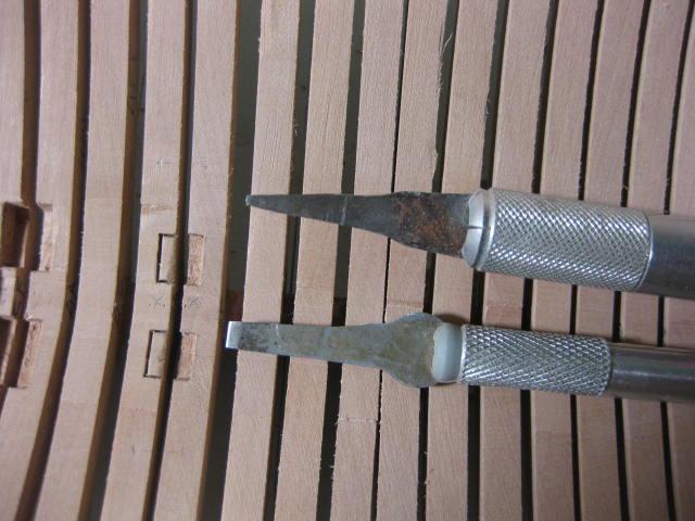
Pump Recesses Recesses for the Pump Intakes were cut into the frames adjacent the keelson with modified Xacto chisels. The keelson was only partly fitted at this point to facilitate the cutting :
-
Keelson The Keelson is made from five sections which are all Hook Scarfed together : The Keelson glued into the hull on top of the Keel :

-
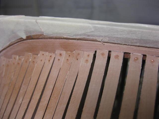
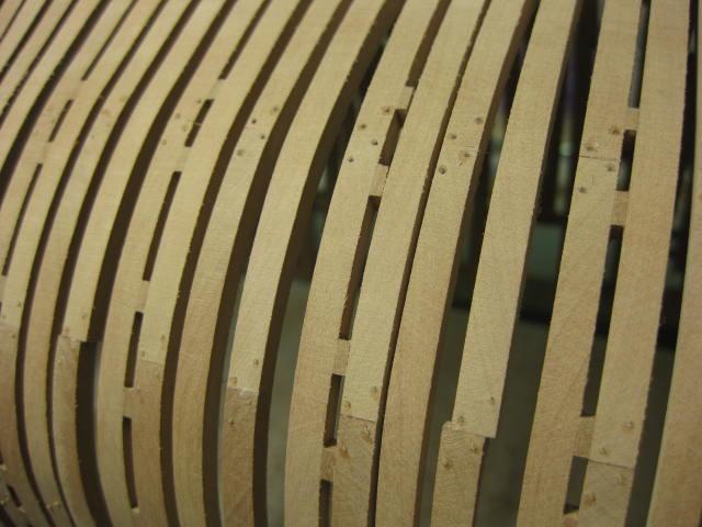
Treenailing Frames I used 0.024" bamboo (pulled through a Jim Byrnes Drawplate) to Treenail the Chocks. Copper wire was used to simulate the bolts in the Keel joints : The treenails after sanding down flush :
-
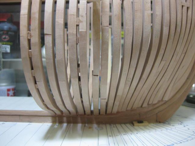
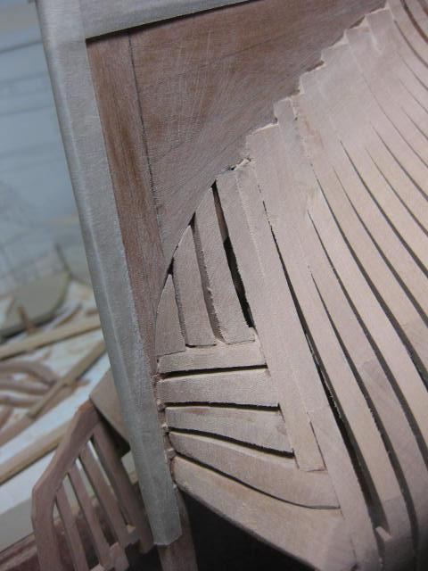
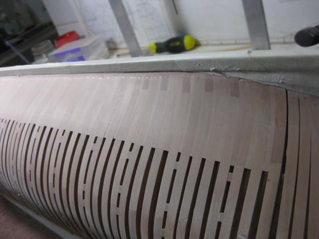
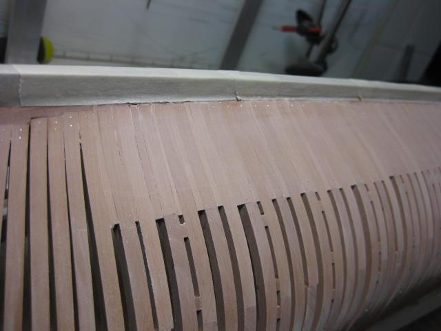
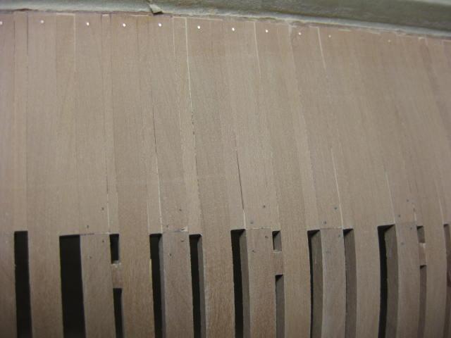
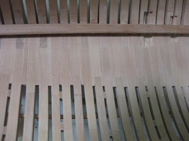
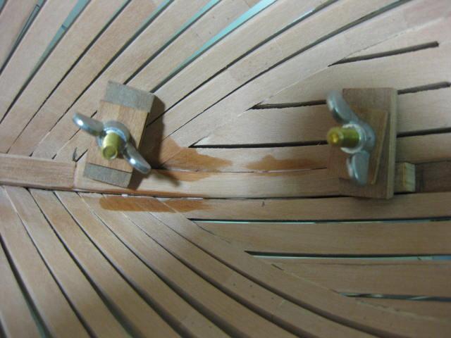
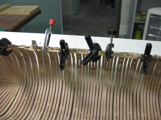
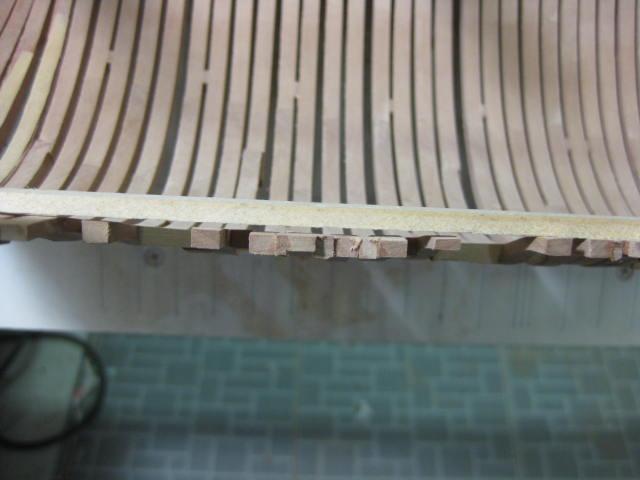
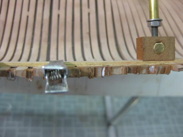
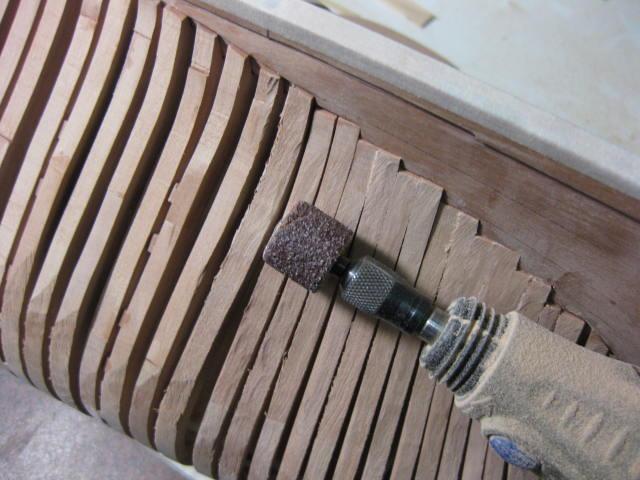
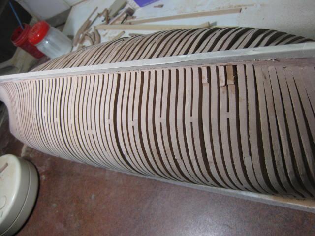
Toptimber Aligning and External Fairing The Toptimbers needed to be aligned next. I glued several pieces of planking to the tops of them, using clamps to pull the top parts together. These planks will be removed later as the real planks are fitted. The first pic shows the Toptimbers before final straightening commenced : Fairing the outer side of the hull started with a drum sander in a Dremel. A delicate touch was needed : A sanding block with 80 grit paper was used next to get the hull nicely Faired. 180 grit paper finished the open Starboard side :

-
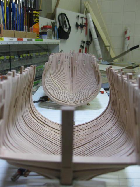
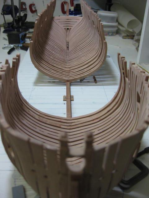
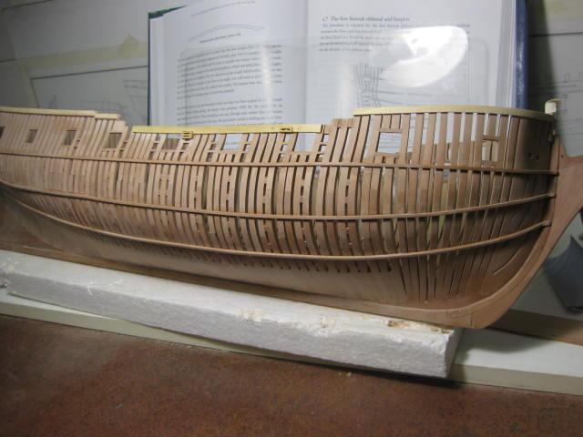
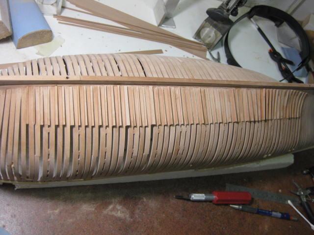
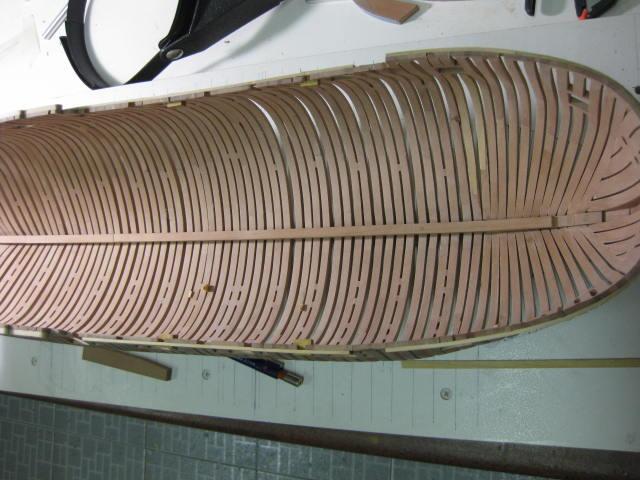
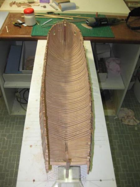
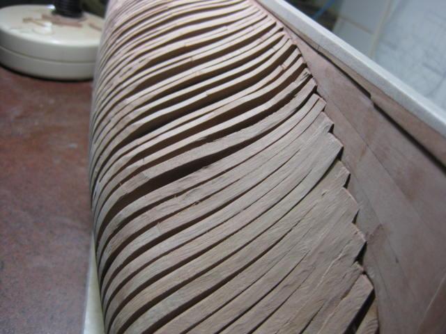
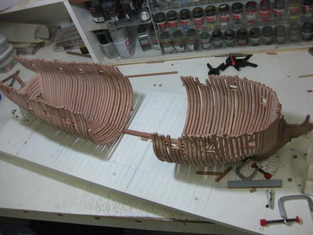
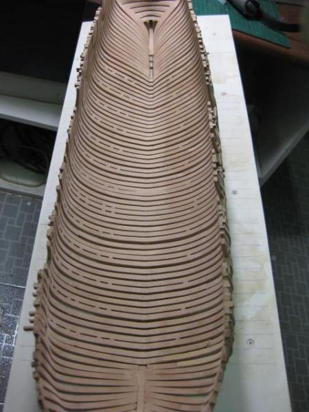
Frames all Fitted Work continues on fitting the rest of the Square Frames. I fit about 8 frames from each end at a time and Fair the insides to make access easier : The Deadflat Frames - Station 0 - are made by joining three frames together with spacers : An overall view of all the frames fitted to the keel. The Gunport Sills were all cut in and fitted as I did each section of framing :


-
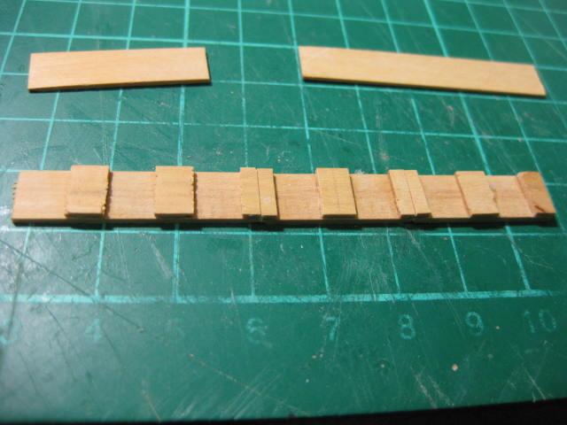
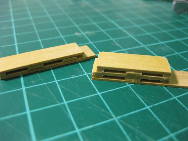
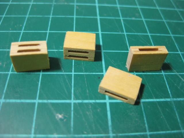
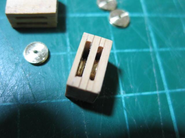
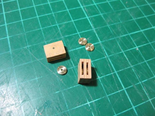
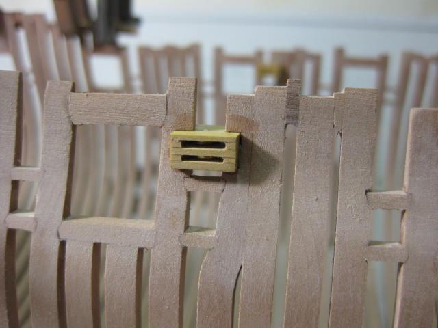
Fixed Blocks There are two Fixed Blocks each side of the hull in the Waist - one single and one double. The single block is for the Main Tack, and the double block is for the Fore Sheet and Spritsail Sheet. These were made by laminating spacers between two strips : They were then sanded to size on the disc sander and the slots were cleaned up with a thin needle file : I turned the Sheaves on my lathe. The larger ones are 0.9mm thick and the smaller ones are 0.75mm thick. They are 4.8mm in diameter : The blocks were later morticed into the frames :
-
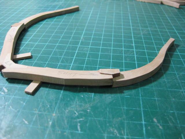
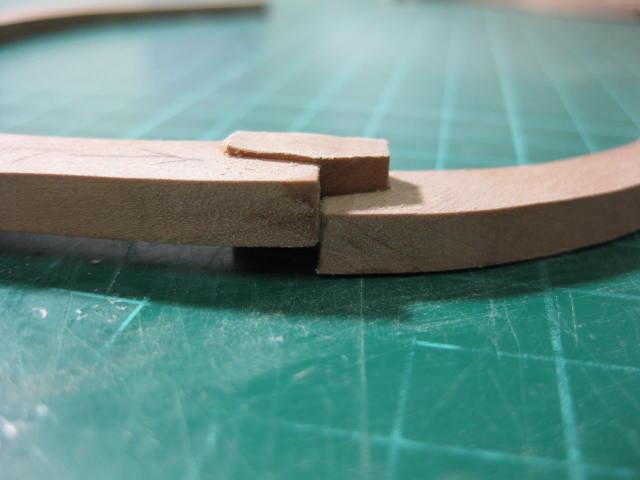
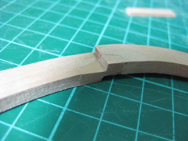
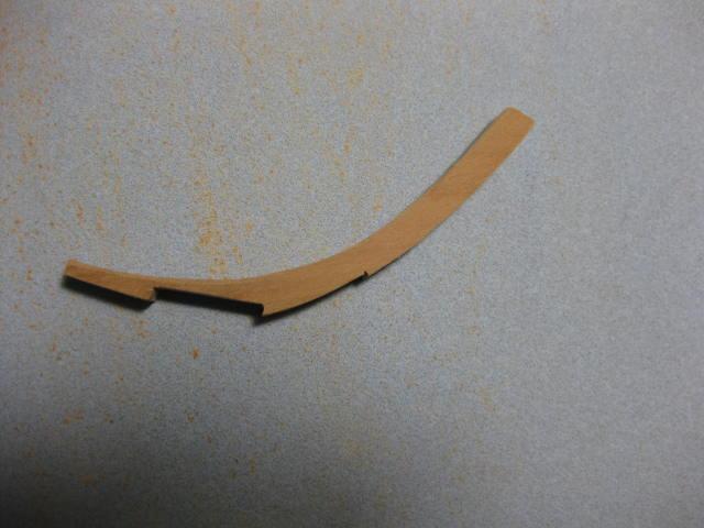
Shifted Toptimber Toptimbers were "shifted" to maintain the correct opening sizes for the Gunports etc. The one shown in the first few pics below (the first one I'd ever made) was actually re-built later on, as I'd miscalculated the correct amount of "step" needed at the join : The re-built frame after being fitted :