HOLIDAY DONATION DRIVE - SUPPORT MSW - DO YOUR PART TO KEEP THIS GREAT FORUM GOING!
×


Dan Vadas
-
Posts
3,261 -
Joined
-
Last visited
Content Type
Profiles
Forums
Gallery
Events
Everything posted by Dan Vadas
-
And thank you too espiegle . Hi all, I've finally completed the Resurrection of my previous Build Log (and Saved it all ). Time to get back in the workshop (when the smell of that dead mouse fades away - you reckon I can find the thing ??? ) Danny
-
Thank you Karl . Hi Laman, It was Evergreen plastic tubing, available in the Model Railroad section of most good hobby shops. I heated the end with a flame and pushed it down onto a steel plate to flare the ends. Danny
-
Finding a log
Dan Vadas replied to Robert Watzke's topic in Using the MSW forum - **NO MODELING CONTENT IN THIS SUB-FORUM**
Hi Robert, Read THIS POST - it looks like Gene still has some of his Build logs saved and is wanting to re-post them . Danny -
Thank you very much Bob, Brian, Grant, Pat, archofo and Sherry (I see you've changed your Username - welcome to the "Dark Side" ). Grant and Pat and anyone else interested, Here's a Link to my "Making Clamps" Tutorial in the "Modeling Tools and Workshop Equipment" forum : Useful Clamps for Fully Framed Models (and other models) by Dan Vadas Danny
-
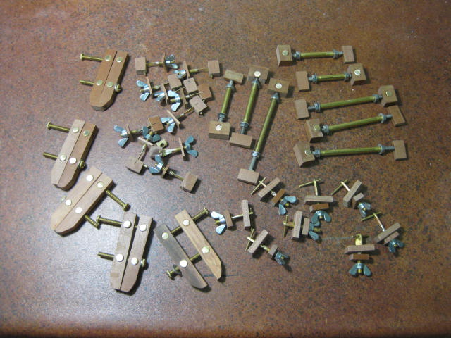
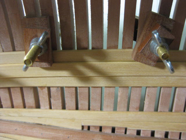
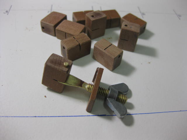
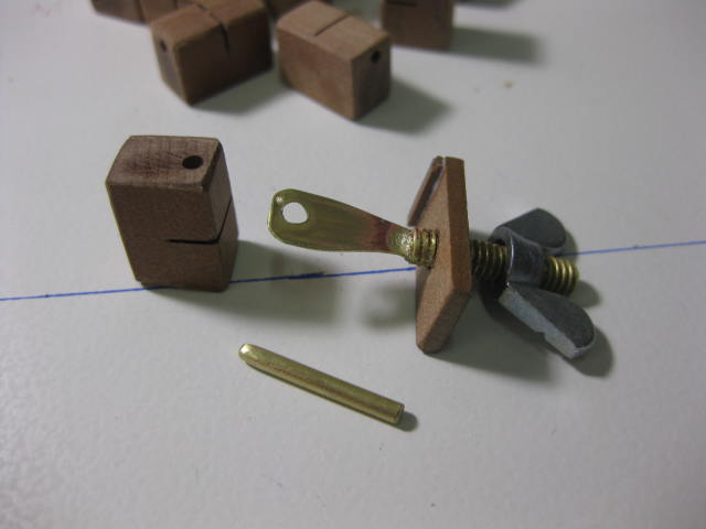
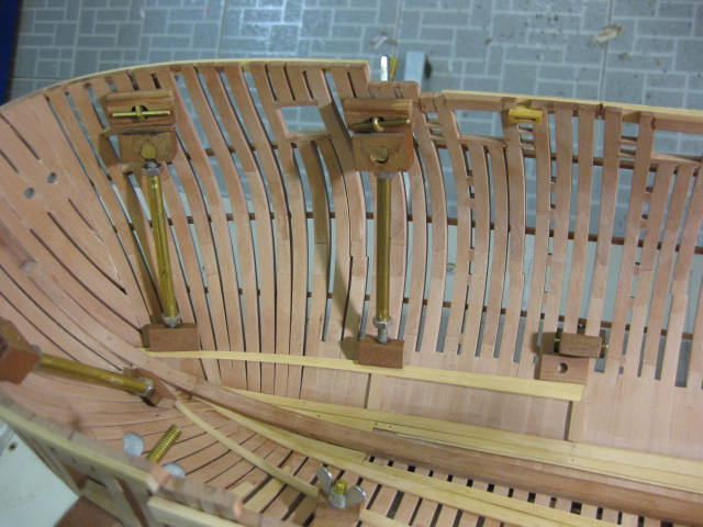
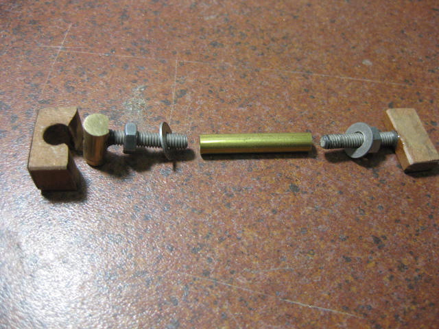
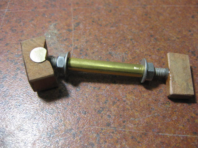
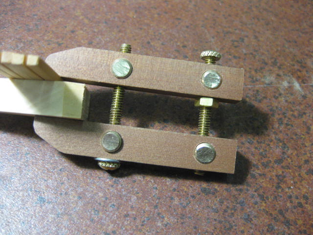
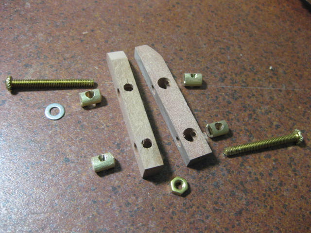
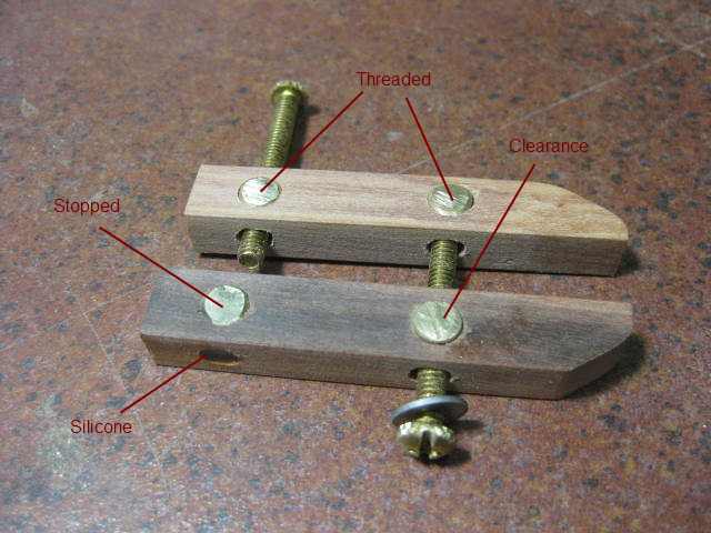
Hi all, I've had several requests to show how I built some special clamps that come in particularly useful if you are building a Fully Framed hull. They could also come in handy for other more "conventional" builds. There are three types of Clamp : 1. The first goes between Frames to hold internal or external planks. 2. "Spreader" clamps that hold internal planking. 3. Parallel clamps that don't pull two pieces out of line like normal spring clamps have a tendency to do. Full Credit for these clamps goes to EdT (Ed Tosti) - I'm only showing my method of copying his ideas. Ed's are probably of superior quality to mine - I've used a more simplified approach that can be done fairly easily by most builders using common Right-Hand threaded screws. "Between the Frames" Clamps In Use : These are made from 3/4" x 5/32" (19mm x 4mm) brass machine screws or threaded bar and matching Wing Nuts - I found them at Bunnings, but they should be available at any reasonably good Hardware Store. The other brass part is some thin brass strip - I used 0.5mm. Note that you can use any sizes of screws and strip - I just used whatever I had "on hand" or could buy easily. I wouldn't go much thinner than the 0.5mm strip though - it's plenty strong enough and will fit right down into very narrow gaps between frames. I cut the heads off the screws, cut a 4mm deep slot into the cut-off end and Silver Soldered the two pieces together. Then I drilled a 2.5mm hole to accept the 2mm Pin. A bit of "oversize" makes it a lot easier to push the pin through the hole. The wooden pieces are made from a good hardwood - I used Australian Cherry Ballart because I had quite a bit of it in stock, but any other close-grained hardwood would do the job. A 2mm hole was drilled for the pin - this needs to be a good but "easy" slide-in fit. The only item of note not shown in the pics below is some extra bracing I glued to one face of the larger block - this prevents the wood from splitting when pressure is applied. It strengthens the saw cut (these pics were taken before I had my first "Block Failure"). Note the direction of the grain in the large block. Spreader Clamps In Use : These Clamps are particularly useful when you need to clamp planking etc and can't use one of the "Between the Frames" clamps, although they can be used in combination with one of them as shown in the pic above. They work very well anywhere inside a hull. I made these in 4 or 5 different lengths depending on the position in the hull they were to be placed. All parts were interchangeable, so a lot of length combinations could be used - the only difference is in the lengths of the brass tubing, the "heads" and "tails" of the clamps are all identical. I used 4mm x 25mm RH-threaded Stainless Steel Machine Screws, Washers and Nuts (again because I had a lot of them in stock - any other combination around that size would be OK). The "swivels" are made from 1/4" (6.5mm) brass round bar that have been drilled and tapped to accept the screws. 5mm brass tubing of various lengths is the only other thing needed. Again, the wooden pieces are made from a good hardwood. The "head" is drilled to accept the swivel, the "tail" is epoxied to the screw to prevent it from falling out when the clamp is tightened. I sanded the end of the "head" to allow it to pivot when necessary. Parallel Clamps In Use : These clamps are particularly useful when you need to clamp two pieces together without distorting their faces from each other. They also avoid the twisting effect that you can get with G-clamps, but are usually used in similar situations to them. They are made from two pieces of hardwood, 8mm x 11mm x 65mm. The same size Swivels as the "Spreader Clamps" are used, with the same size screws as the "Between the Frames" clamps. Again, use any sizes close to the mark that you can get - it's not all that vital. Here's an Exploded View of the Clamp : And a description of how it goes together is below. Two Swivels are threaded to accept the screws, one is a "clearance" hole drilled right through, and the fourth is a clearance hole drilled part-way into the swivel to act as a "stopper". This one is glued into the timber with Silicone or Epoxy. I made about 18 "Between the Frames" clamps, 10 "Spreader" clamps and 6 "Parallel" clamps - that seems to be adequate. Danny
- 12 replies
-
- 16
-

-

-
I checked your Posts earlier and thought it may have been that one . Consider it done. Danny
-
Hi Aaron, I'm not sure a General Member can if it's been replied to. EDIT - I just checked .... you can't No problem for a Moderator though - which Topic are you referring to? I can do it for you if I think I should. Danny
-
Thanks very much Geoff - your comments are appreciated . I'll have to get started on a "Tutorial" on how to make the Clamps and other "bits and pieces". Soon, I promise . Hi all, I've attached ALL the pics in the "old" section of my Build Log. It only ran to 9 pages - some bits have been omitted, "mistakes" are in HERE and other Tips that belong in another Forum will be posted there at a later date. I still need to add Text to most of the Posts, but that is happening already and will continue until it's all done. THEN I'll be able to get back to some REAL WORK on "Vulture" . Danny
-
Hi Pat, That's exactly how I'm doing it. You bet it is. I haven't done ANYTHING on the Build since we went to MSW v2.0 (pre-Crash) . Danny
-
Thank you Joe and Aldo . I hope to have it all finished to the stage it was before the "Big Crash" in about a week or two. Unfortunately a lot of stuff from the old Log can't be recovered, but the new Format I'm using for that part of the Log is a lot easier to read through. Hi all, I have done an Update to the Information in the top of my Index explaining what will be happening as work progresses on my Build Log Reconstruction. The Links to posts will be added, or change color, depending on the stage I'm up to at the time. Danny
-
Build Log Reconstruction Update : I have attached all the Pictures up to the start of Page 6. Text still needs to be added for Pages 3 to 5, that will start happening when ALL the pics have been attached up to Page 10. Danny
-
Thanks for looking in Mark, Joe, Alex, Toni, Sjors, Kevin, Frank, geomac6305 and Christian. I hope you all continue enjoying the Log as it starts to fill up . Toni, you're doing a GREAT job on your "reconstruction" - that's a huge amount of re-typing compared to mine . Sorry Frank, but the Build Log of "Supply" won't be re-surfacing (I'll post some pics of the Completed Ship in the Gallery though) - I only have ONE lifetime left to do the things I want to do . Hi all, Further additions to my Build Log have been completed - nearly finished Page 2. Danny
-
Welcome back John . I'll be following with interest as usual. What? You don't save ANY of your pics??? Why on earth not? A hard lesson, what happened a week ago . Cheers, Danny
-
Thanks Scott . I hope the Rebuilt Log won't be a disappointment, but I've had to leave out a lot of the details I put into the old one - I'm trying to do the job in THIS lifetime . I've finished the first 9 posts (ONLY 110 to go ) and I'll be doing as many as I can each day until I get back to where I was before the Crash. Click on the "HMS Vulture" Link in my Signature to get to my Index. Cheers, Danny
-
I see you did Toni . The right margin is "everywhere" because the Text Editor doesn't have a "Justify Text" option which stretches out the spacing between words and letters to line up both margins. The differences in the spacings depend on the length of the next word. That sort of option is only available in more complex programs like MS Word and would use up too much memory on this Site. Don't worry about it - everyone's in the same boat (groan ). BTW - you were getting a lot of blank space after your last pics. When Editing, place the Cursor directly after the last actual entry and hold down the Delete Button. This will clear any extra space. (I've already done that for you) Cheers, Danny
-
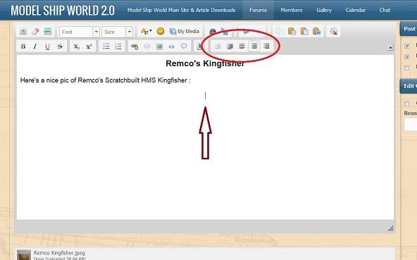
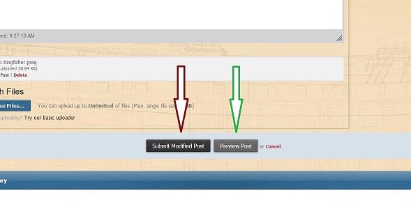
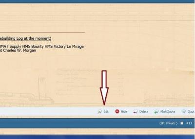
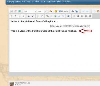
Hitting the Enter key while you are in the Edit Box will send the Cursor down one line - it's a good idea to leave at least one blank line between your Text and the Picture, otherwise the Text can look "crowded" with the picture. Play around a bit with the Formatting Icons until you are happy with the way it looks. Using the "Preview" button shows how the Post will look before it's Submitted, but some of the Text may be Justified slightly differently. Your Post can be Edited at any time if you find you've made a mistake (spelling, layout or other) - Just use the Edit button at the bottom, as shown in the 1st pic of the main Post above. Cheers, Danny
-
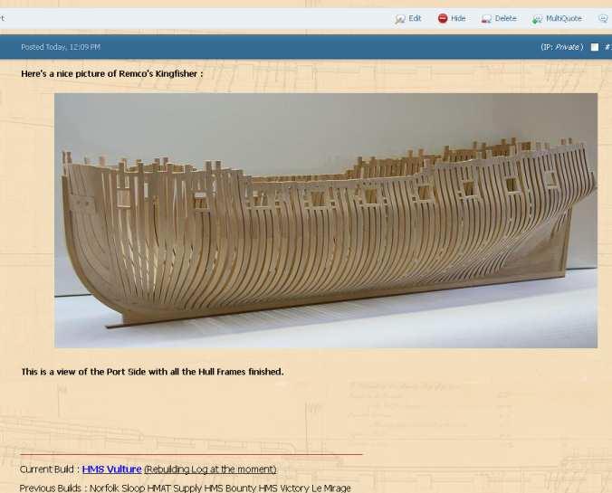
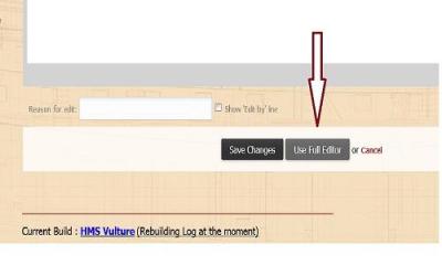
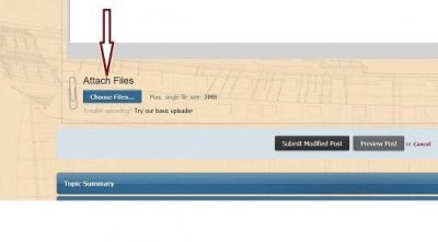
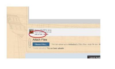
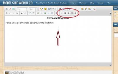
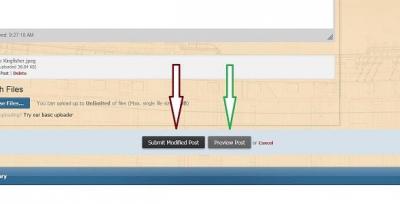
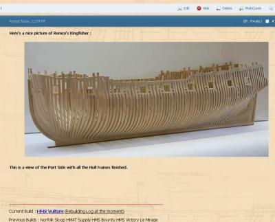
How To Add Pictures in your Posts and PMs 1. Open the Edit Box by clicking the "Edit" at the bottom of the Post : 2. Click on the "Full Editor" button : 3. Click on the "Choose Files" button : This will open a Dialog Box to your Computer Files. Select the picture file you want to add and click "Save" (or "Open") to upload the picture. 4. Place the Cursor where you want the picture added. You can use the Icons (circled) to position it on the line : 5. Click on the "Add to Post" text under the Thumbnail of the picture. This adds the Attachment Code into the message at the position you selected : 6. You can add more Text after the picture if you want, or add more pictures (limit of 8 per Post). 7. Click on the "Submit" button. You can use the "Preview" button to make sure your layout is OK before clicking Submit. If you need to Edit your Post again simply restart the process by clicking on "Edit" again. You MUST use the "Full Editor" to post extra Pictures. A view of the completed Post with Text and Picture Added : . PLEASE NOTE THAT THIS TUTORIAL IS FROM THE PREVIOUS VERSION OF MSW AND NO LONGER WORKS AS DESCRIBED. AN UPDATED VERSION WILL BE POSTED SHORTLY.
- 117 replies
-
- 17
-
-
Hi Toni, Great to see that you've managed to use Dave's saved files to recreate your Build Log. Unfortunately mine were pretty well unusable other than to give me a very good idea of how I set the original Log out. I've taken the liberty of Editing your first "New" post to set the layout up in a more "readable" fashion. Open your Edit box on it, open the "Full Editor" and check how the Picture Attachment Codes are now placed. If you set the Cursor in the Text Box where you want the pic to be and then clkick on the "Add Post" button under the thumbnail of the pic it will place the code here. You can Centre it if you want by Selecting the Code with your mouse and then click on the "Centre Text" icon at the top of the Edit Box. Cheers, Danny
-
Gee Grant, thanks a lot - it was a pleasure meeting you too . And rest assured the rest of the bottle of Glenfiddich certainly won't go to waste . Cheers, Danny
-
This post concludes the "Resurrection" of my Build Log. From now on it's back to my more "normal" style, with comments from other members and more "in-depth" explanations of how I build certain things. All MISTAKES will also be documented from here on . , Danny
-
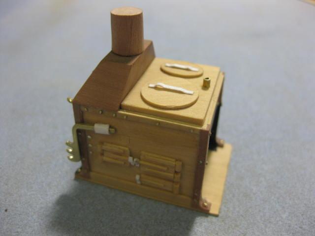
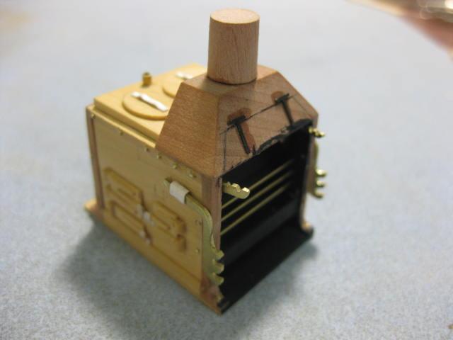
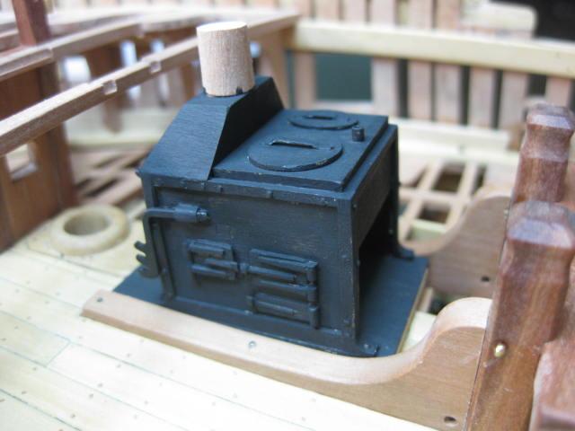
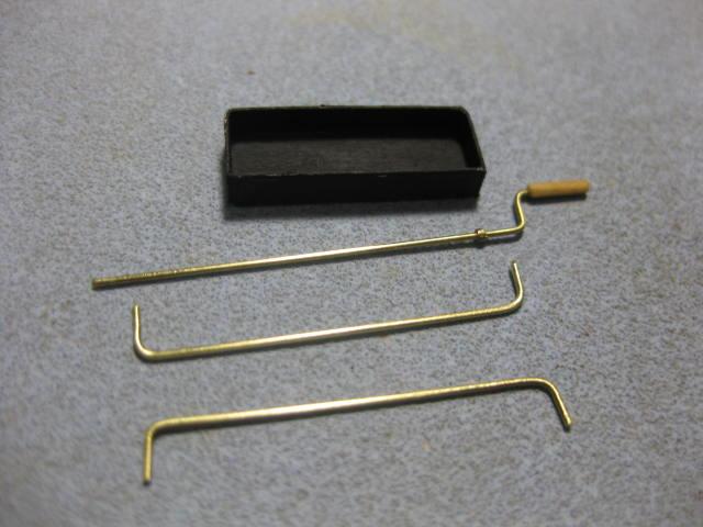
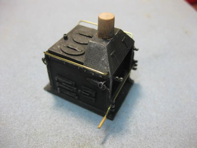
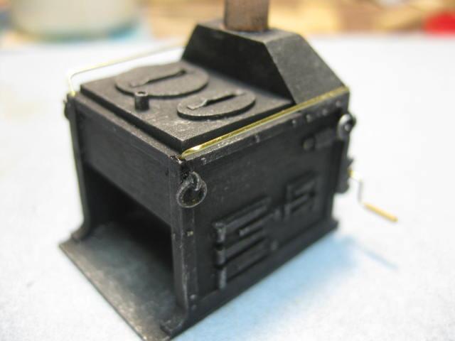
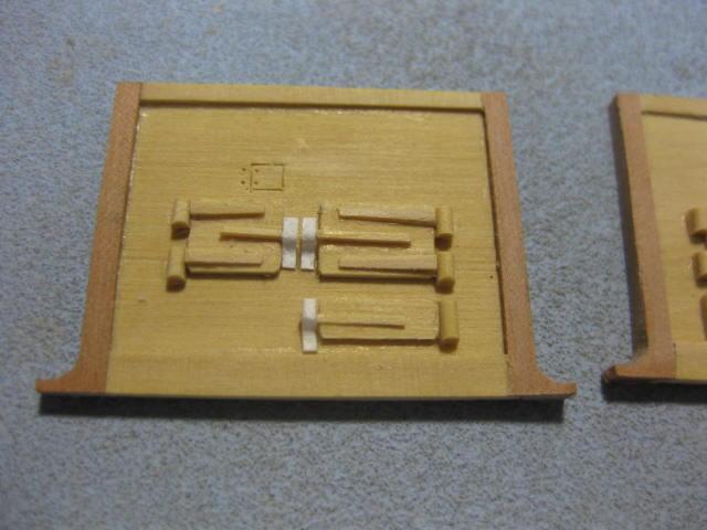
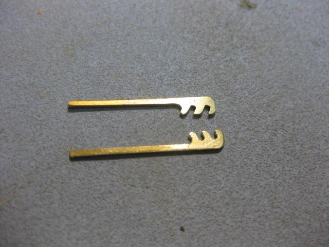
Galley Stove 2 The Pot Arms were filed from brass strip : There are two Boilers - a large round one and a smaller oval one. The lids for these were made from Box : The inside was painted Matt Black and the 0.5mm Grating Bars were fitted : Paper Pot Lid Handles and Spit Support Brackets were added, also all the rivets which were made from rounded brass wire. The dowel on top of the Cowl is a support for the Chimney : Finally two small hinges from the PE set were added for the dummy lid : The whole stove received a coat of Matt Black : The Ash Box, Side Rails and Spit : The Lifting Rings have been fitted and the stove has been dry-brushed with silver to highlight the various components. The brasswork has also been added - this will be left as brass for a little contrast and better visibility :


-
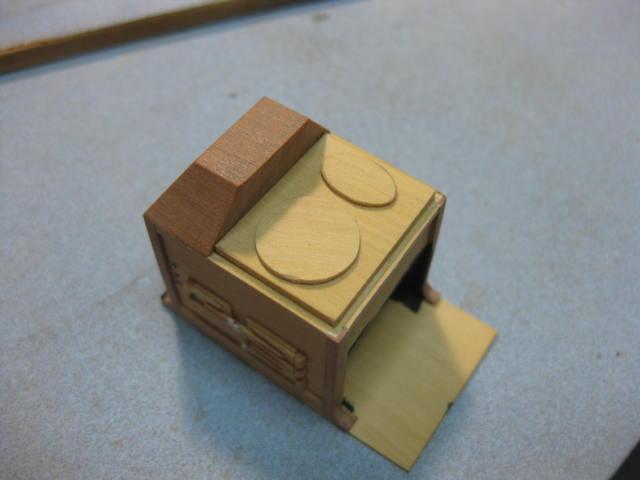
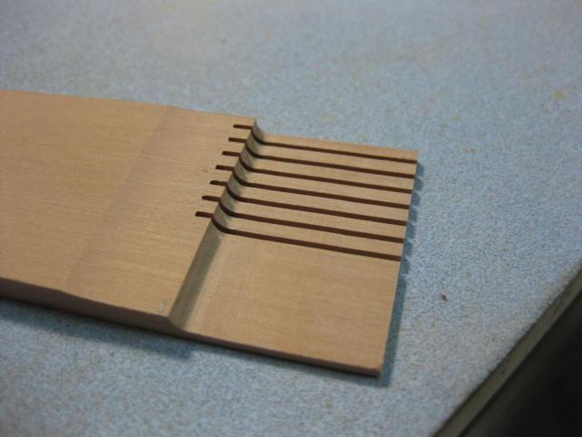
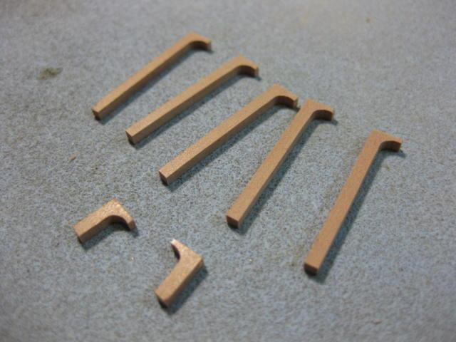
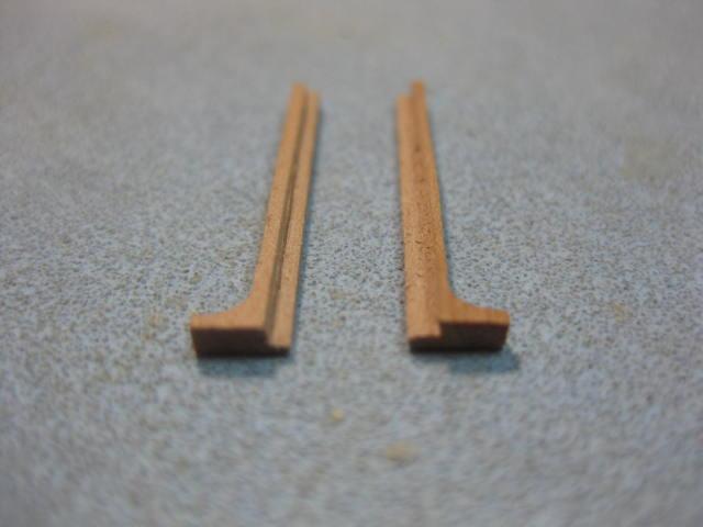
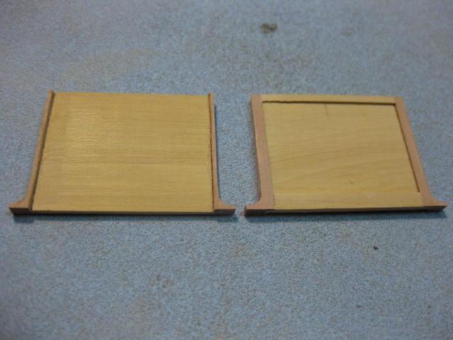
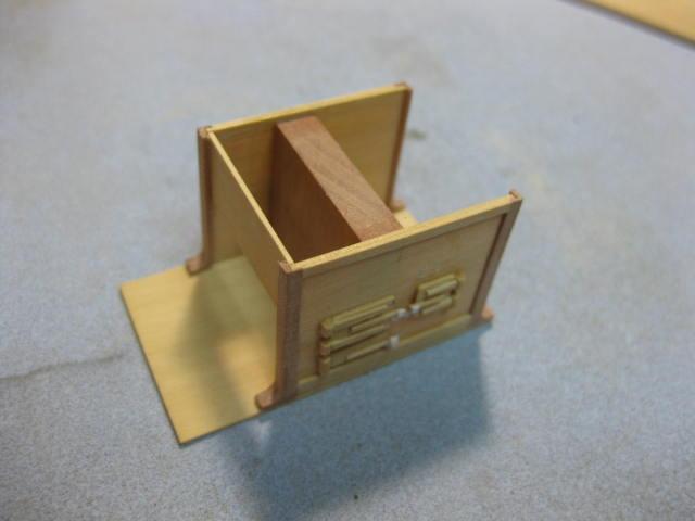
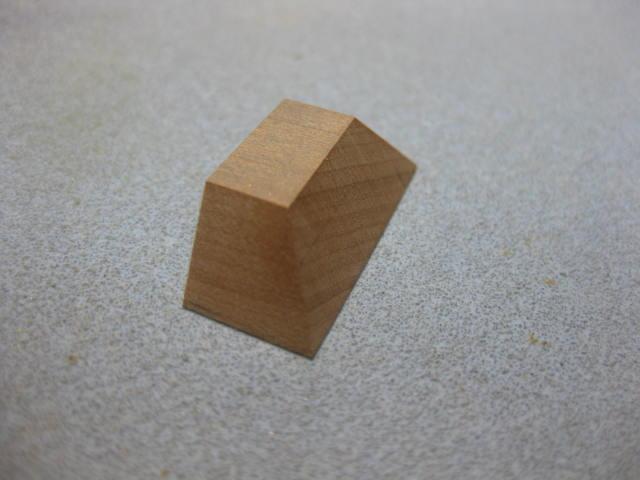
Galley Stove 1 Choosing the method of construction of the Galley Stove caused me a few sleepless nights - I wasn't confident enough in my brasswork and silver soldering techniques to attempt to make it from brass sheet like some others have, so I decided to go with a medium I was comfortable with - Wood. I've used English Box for the flat sheets, with Swiss Pear for other pieces. The first parts I made were the angles for the corners. These were cast iron and have a foot at the bottom which bolts to the floor. I used Pear which I first ran through the Thicknesser to take off the majority of the waste, leaving a foot for the bottom. This needed a little work with a round file to get to the correct radius. Then I cut each leg on the table saw with a few extras in case I needed them : Next I cut a rebate into each leg to accept the sheet sides : The lids were made from Box, the hinges from half-round pieces of the same, and the latches are paper : The supports for the Spit were filed from brass strip : The Cowl was sanded to shape from a single piece on the disc sander using the tilting table :
-
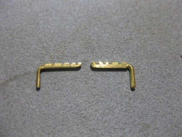
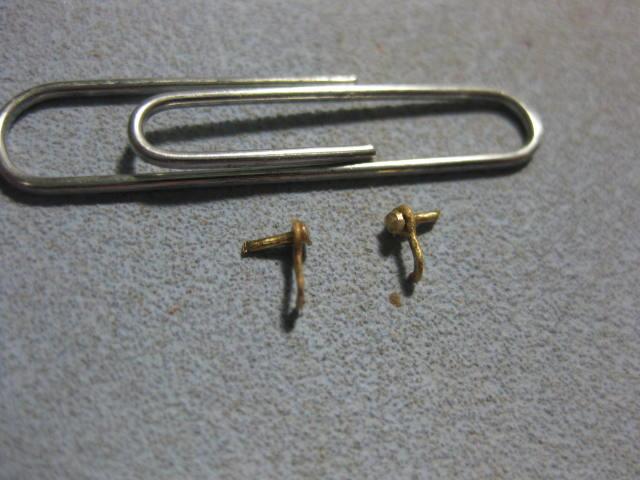
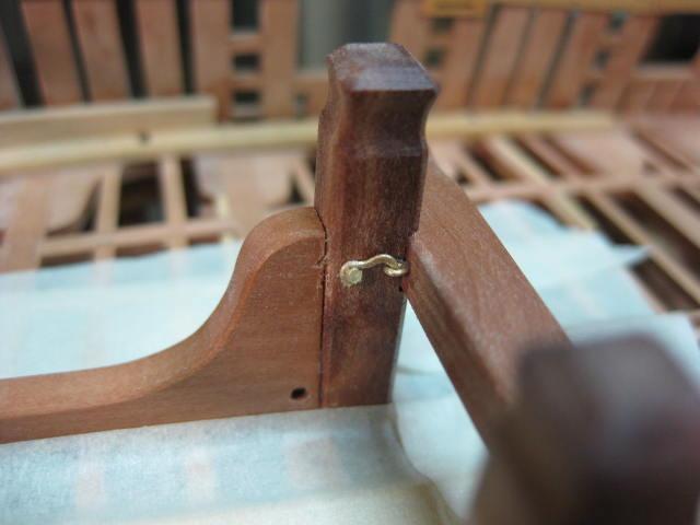
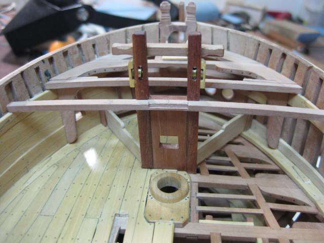
Riding Bitts part 2 The Riding Bitts were now finished off and the Crosspiece made. This is held in place by two hooks and eyes, which I made from flattened brass wire. The riding bitt Standards (the horizontal knees) have also been fitted :
-
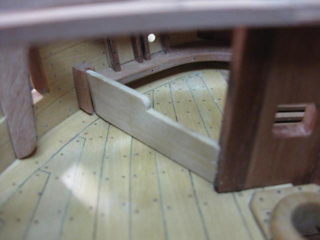
Manger The Manger performed the task of draining off most of the water as the anchor cable was hauled in. There is a scupper in each forward corner to let the water back out. It consists of two removable planks each side which are held at their forward ends by two rebated cants and a rebate at their aft ends in each of the two fore topsail sheet bitt pins :

-
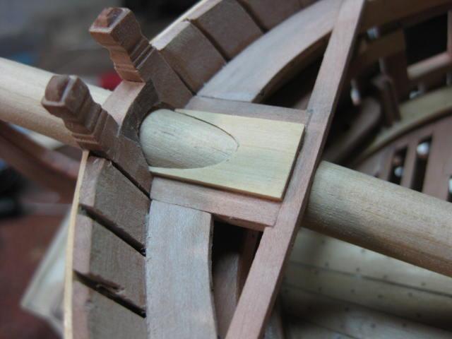
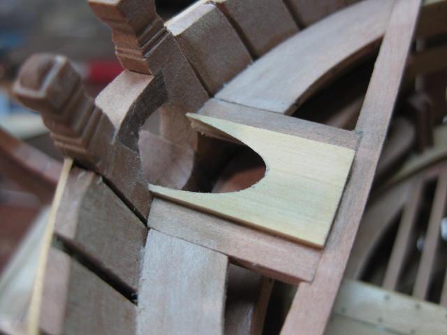
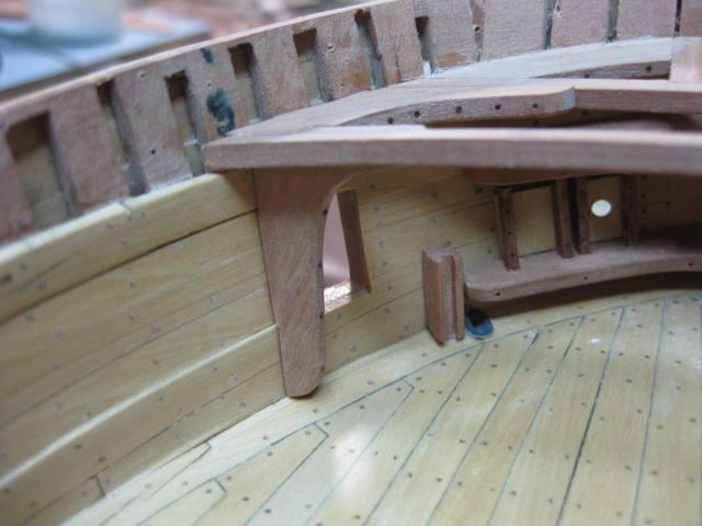
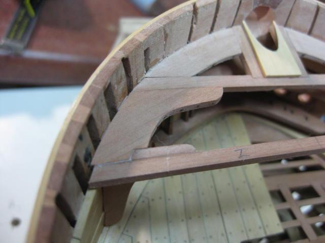
Bowsprit Partner, Hanging and Lodging Knees The Bowsprit Partner is made from a single piece of timber 24" wide and 2" thick. I started out by using a card template, cutting the hole a little undersize. To finish off the angled hole I used the same sliding sanding tube as for the hole between the knightheads and bowsprit chock, but I placed the end of the guide dowel into the bowsprit step : The Hanging Knees for the second beam needed quite a bit of sanding to get them to sit flush with the spirketting :