


mir0n
-
Posts
17 -
Joined
-
Last visited
Content Type
Profiles
Forums
Gallery
Events
Posts posted by mir0n
-
-
-
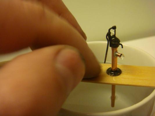
Test drive
In a cup of tap water


-
-
-
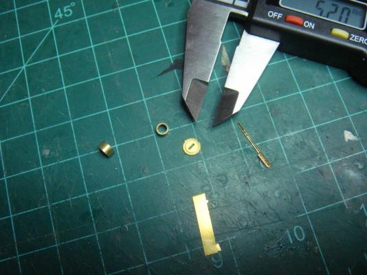
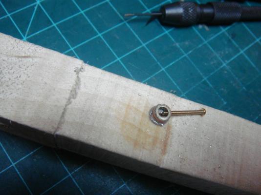
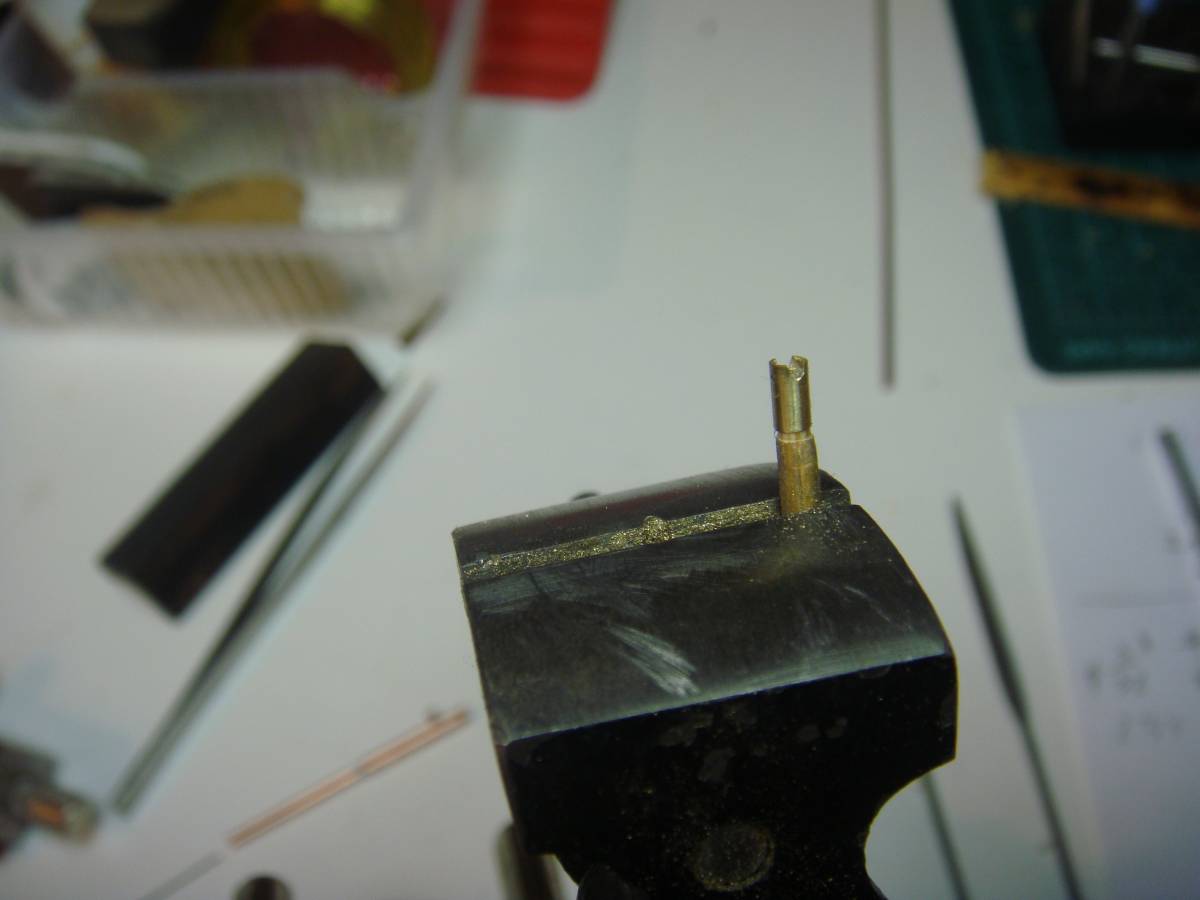
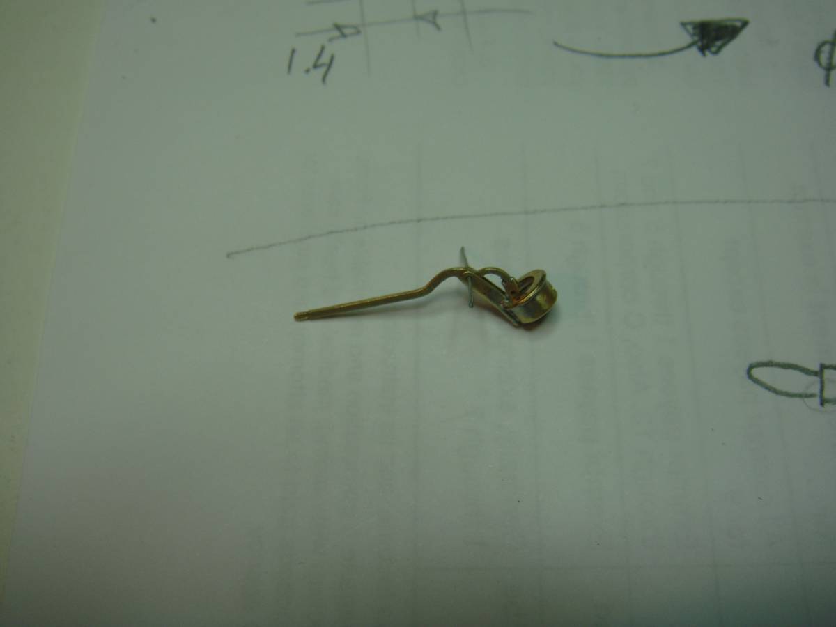
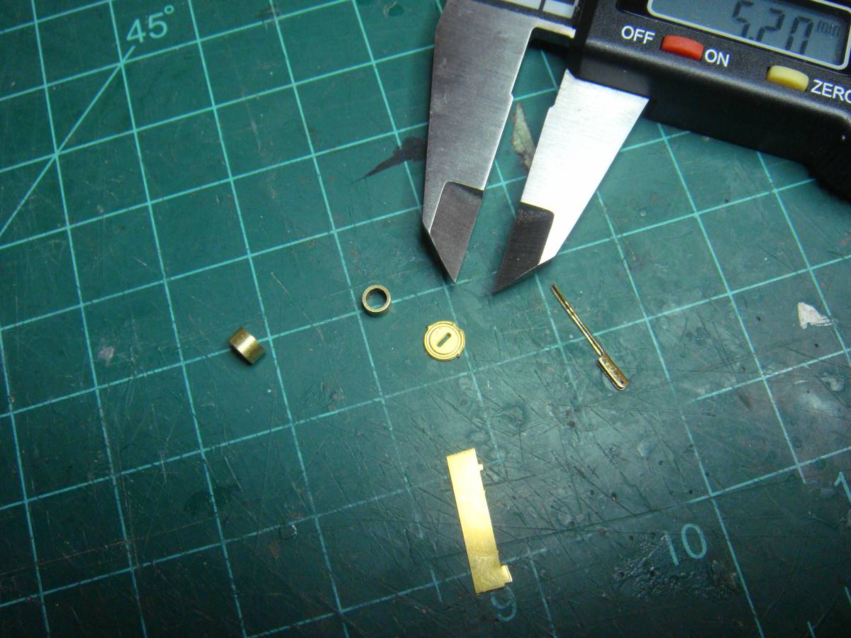
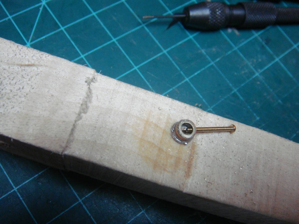
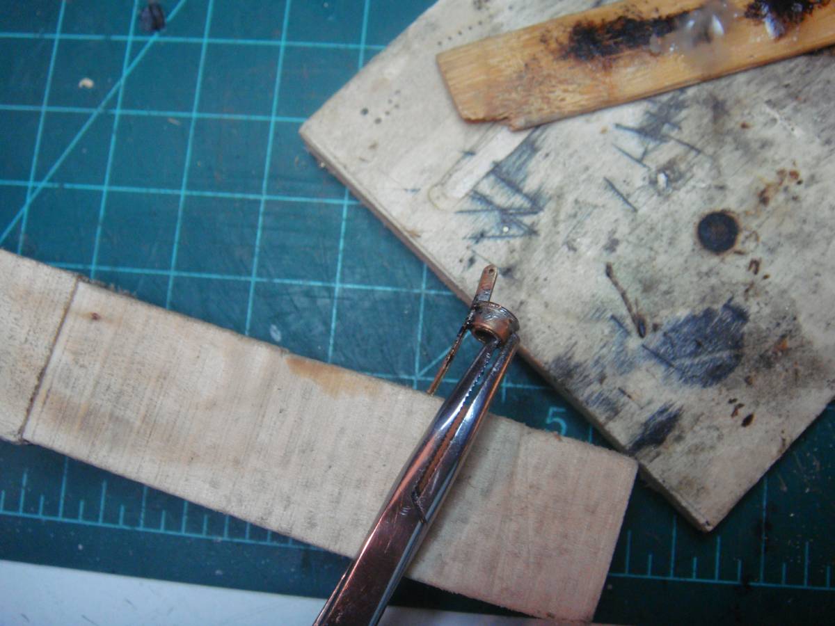
The piston
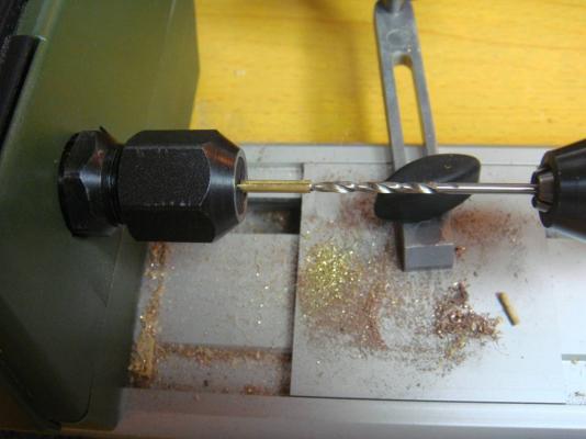
Brass 3/32" tube: Boring to 2.0mm
Well, yes! First there was a hole for 0.5mm axle – no photo left
Boring the edge a little for the stock move

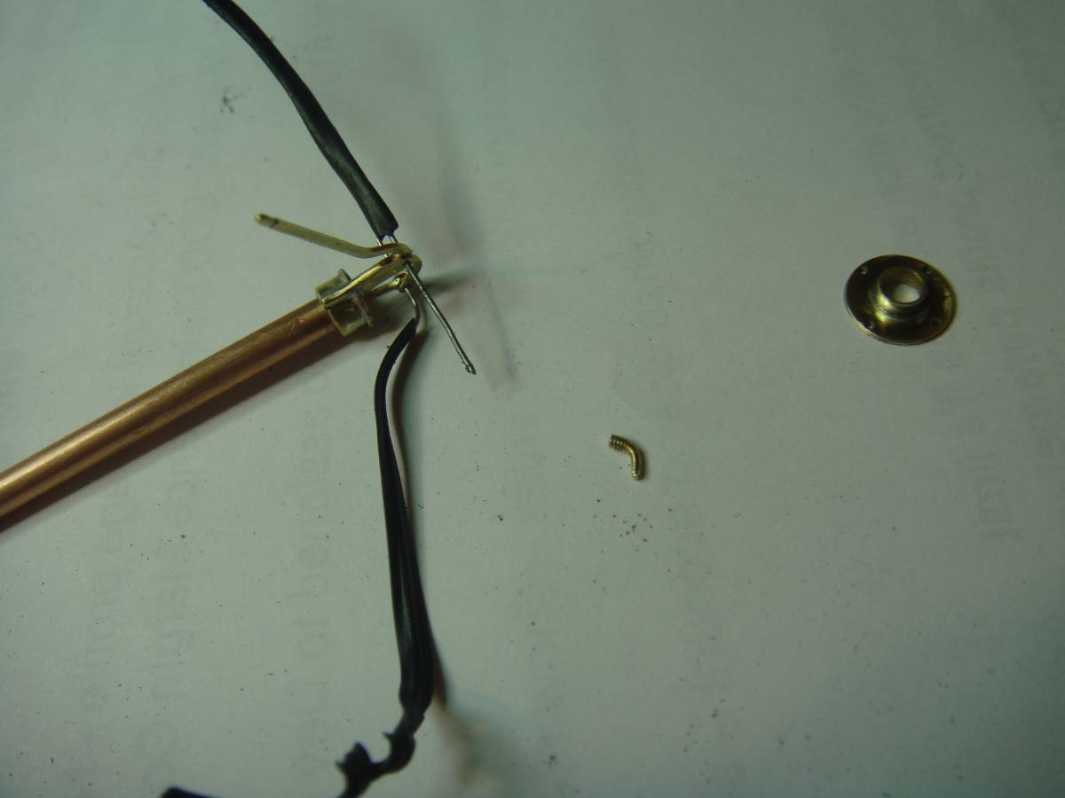
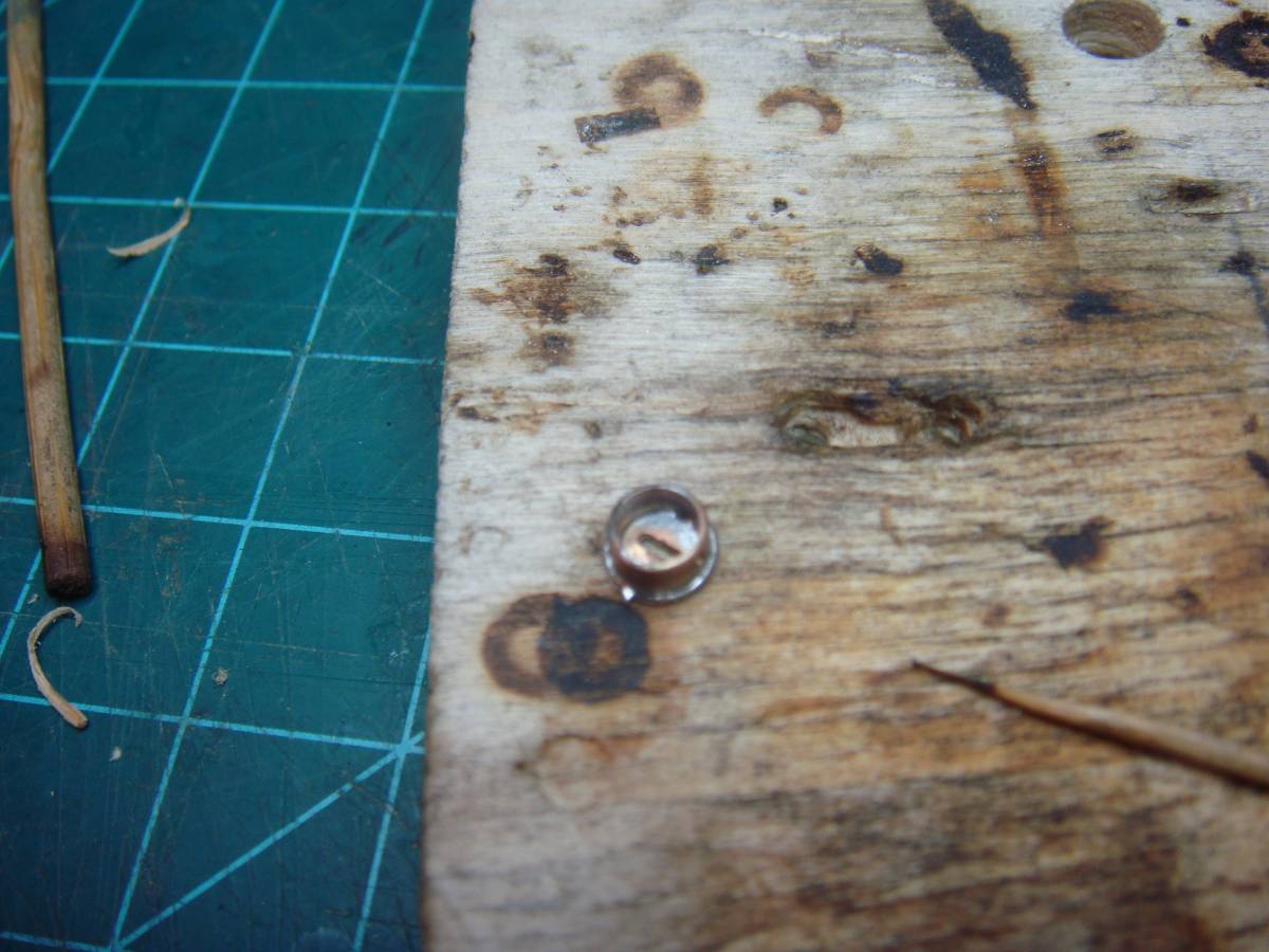
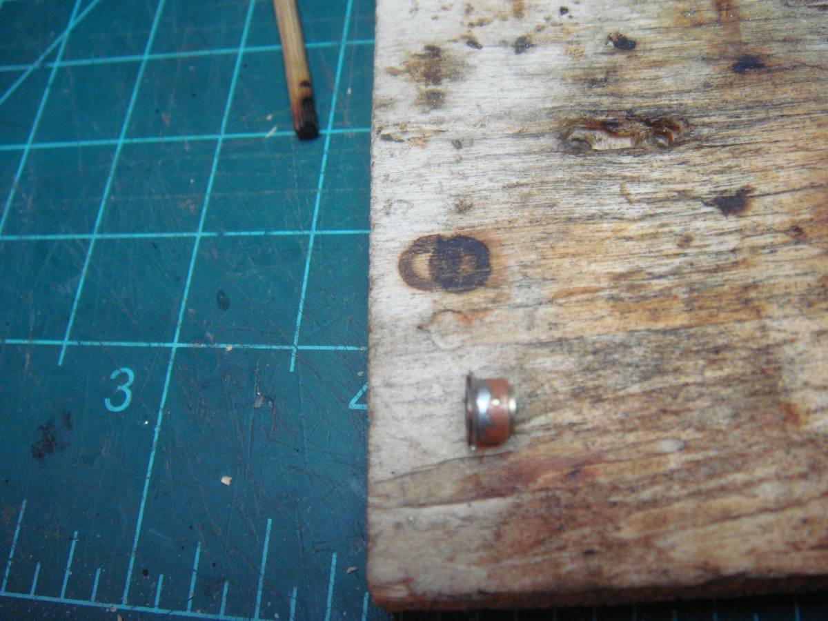
Solder the washer, so that the valve ball is not thrown out of the piston.
Reseating the ball bed with 1/16" sphere inside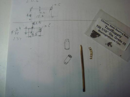

-
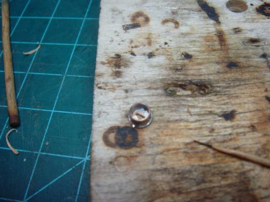
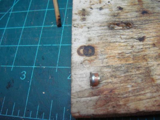
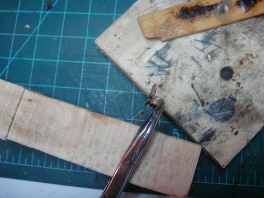
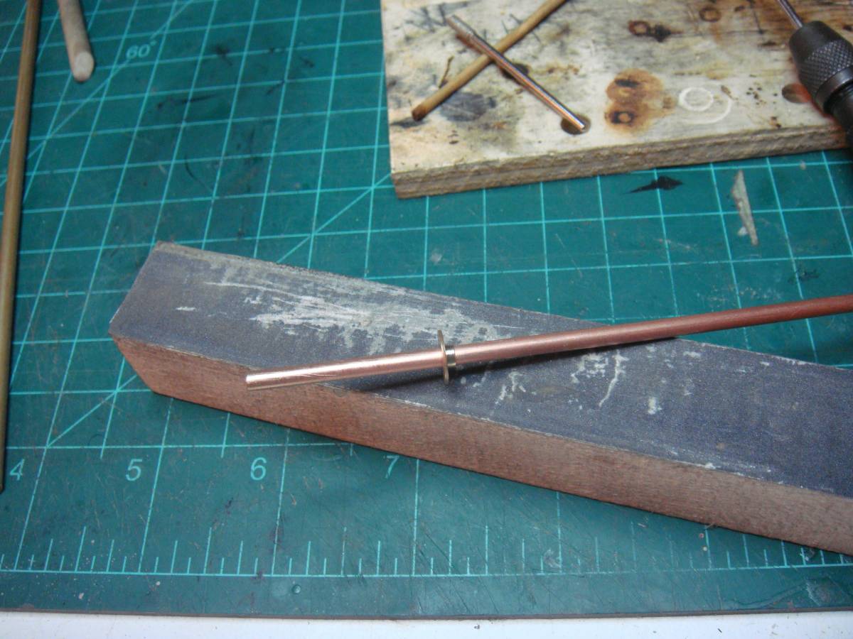
The stock
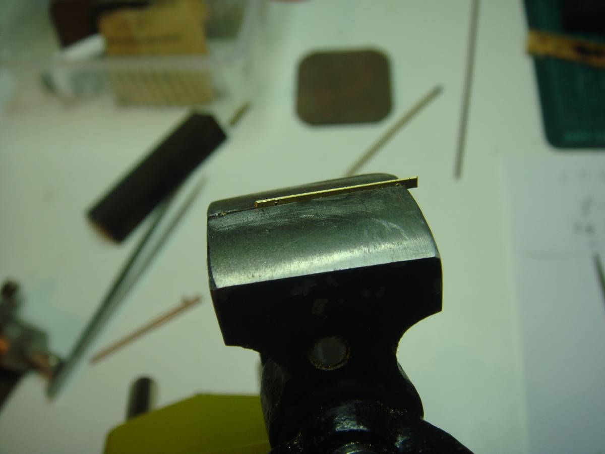
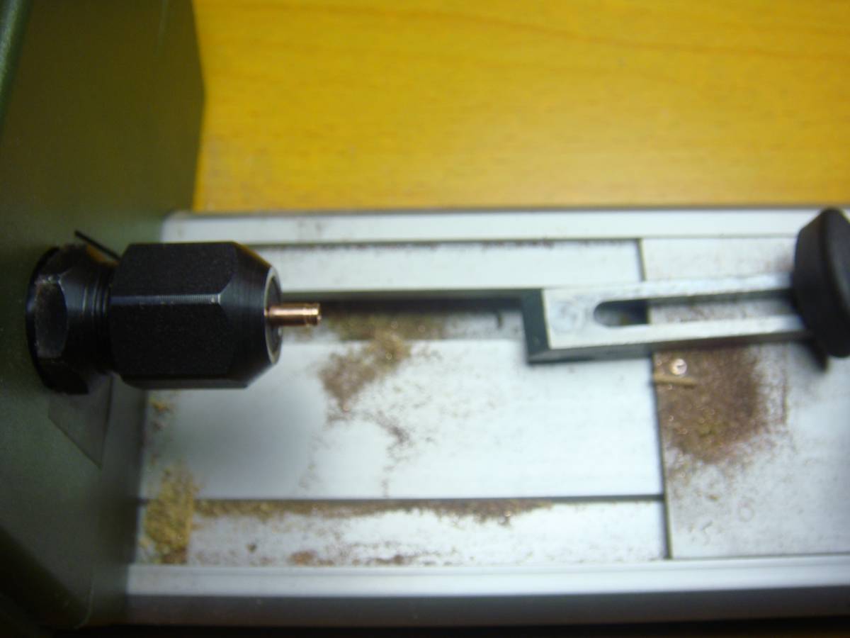
In the strip of 0.6mm brass: drilling 0.5mm holes
Primitive: in a vice with help of file

Done!!!
-
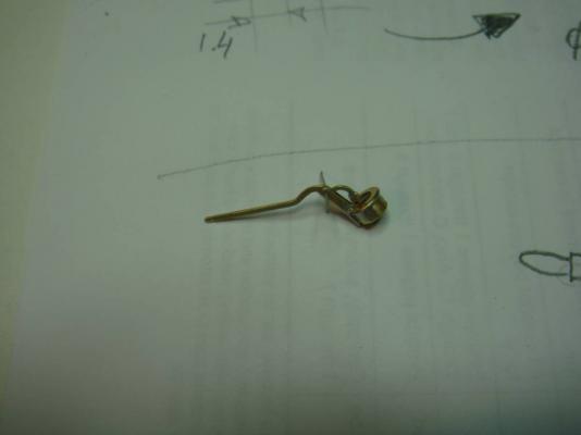
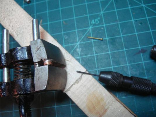
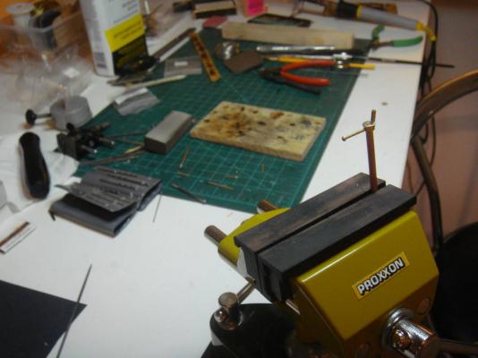
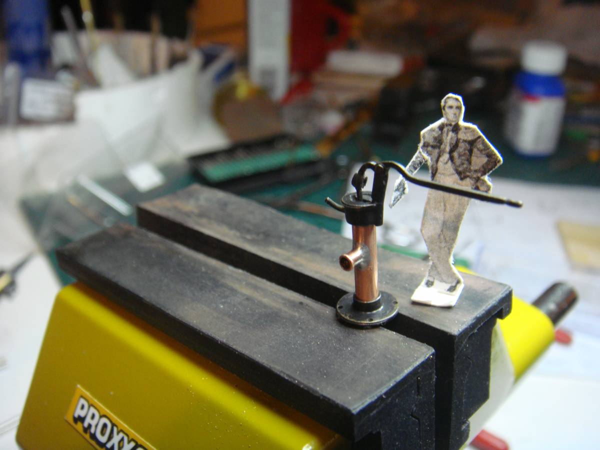
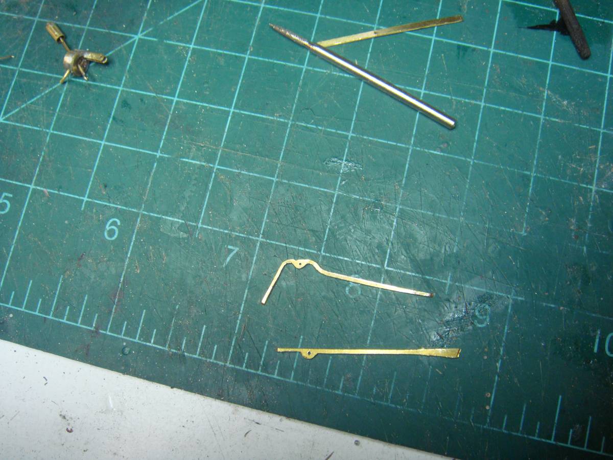
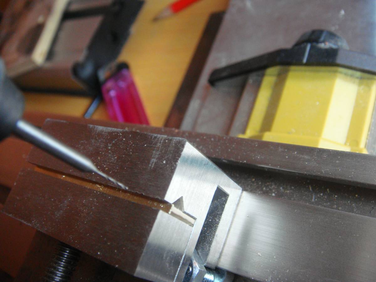
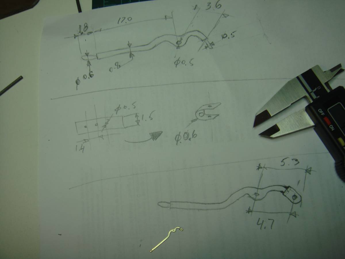
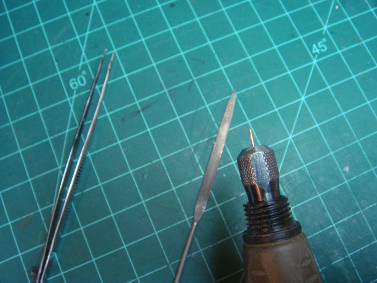
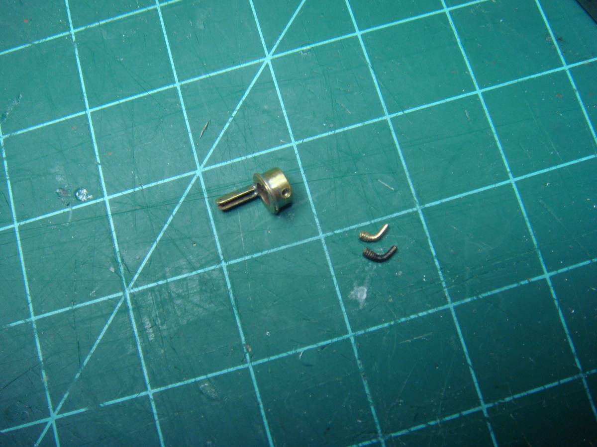
The rocker arm ( The handle)
Brass 0.6mm: cutting out and forming of the rocker’s sly form

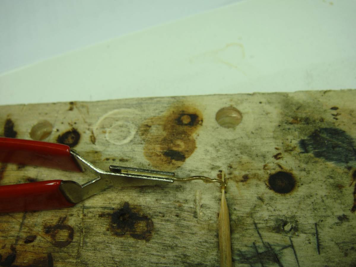
Brass 0.3 mm: drilling three 0.5mm holes with 1.4mm step
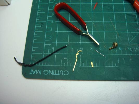
Bending stock holder, whetting the rocker tip up to 0.5 mm
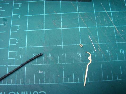
Soldering

Grinding off excess
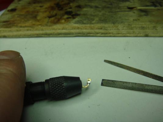
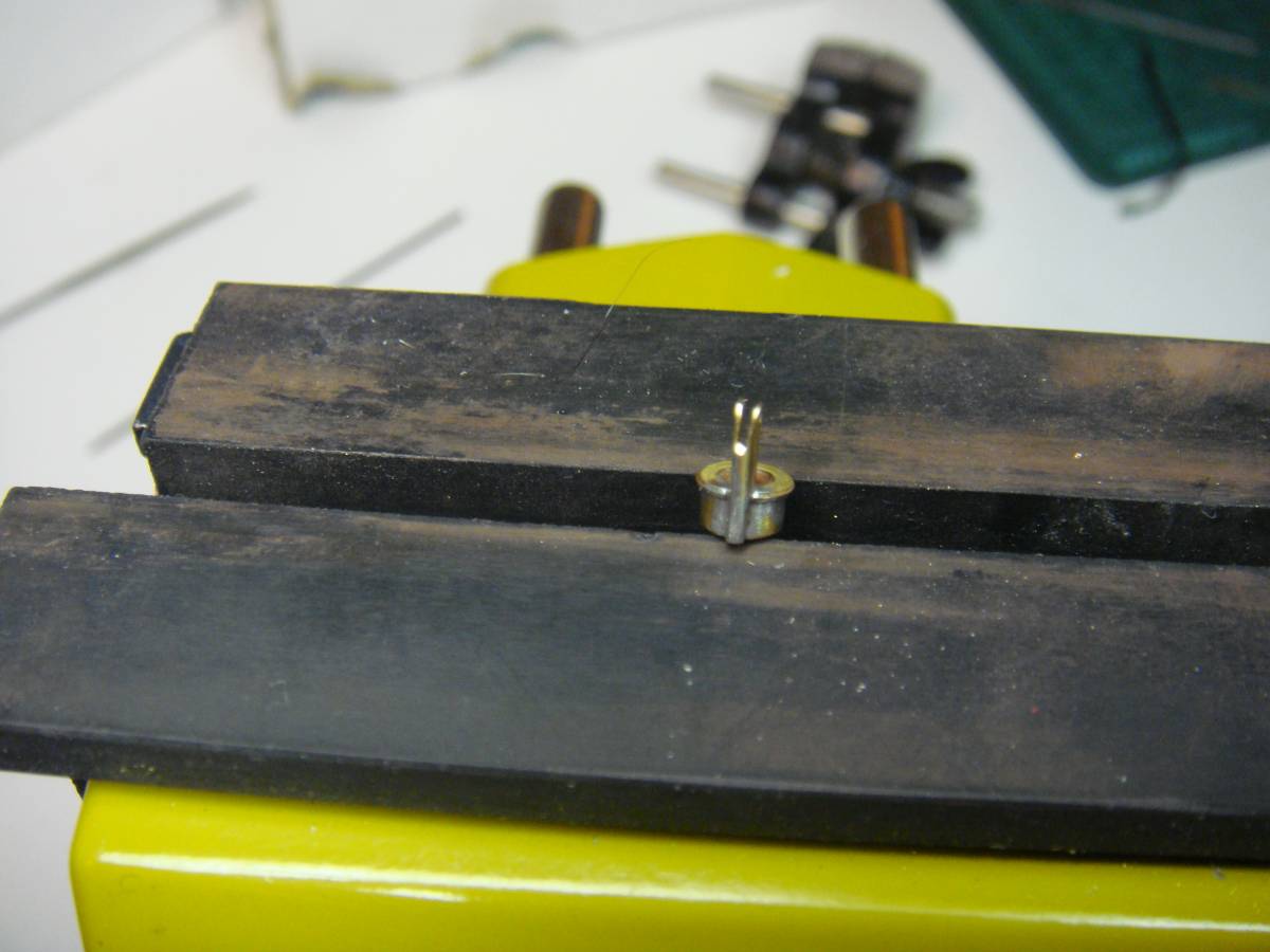
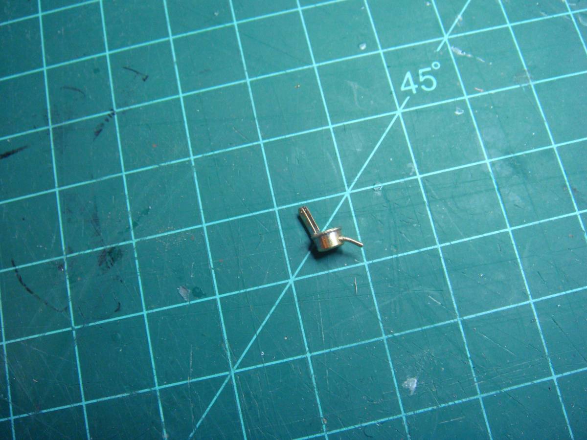
Handle assembled!!!
In handle support: boring a required spot for rocker movements
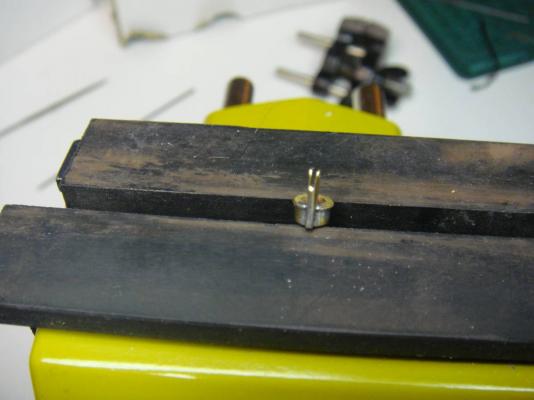
Fitting
-
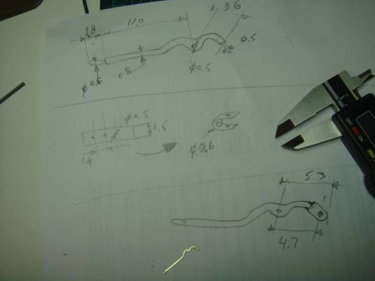
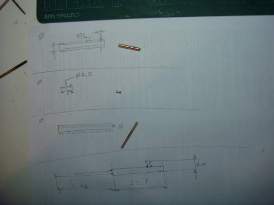
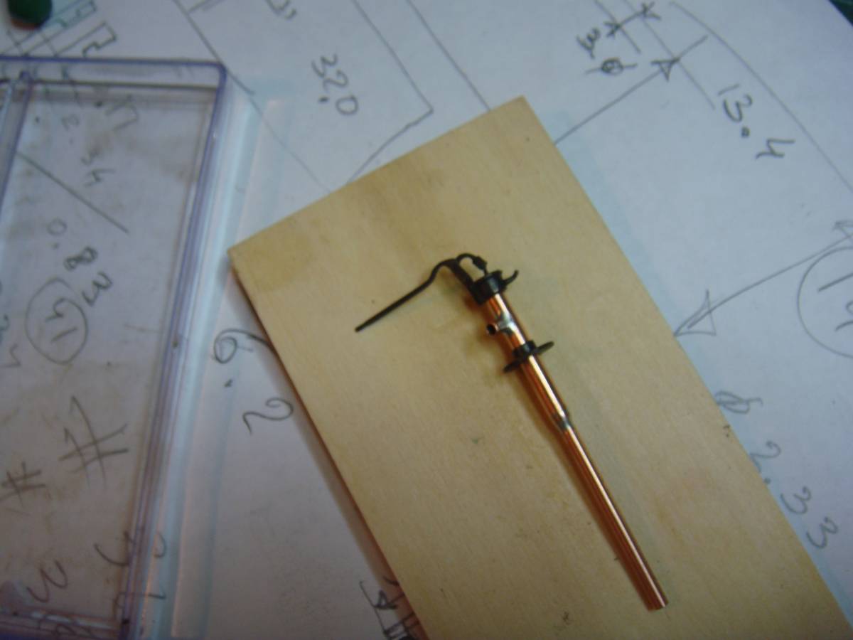
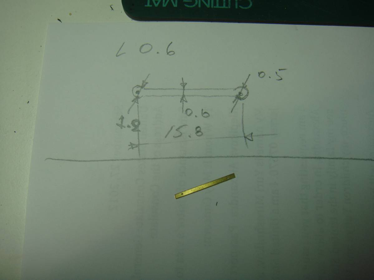
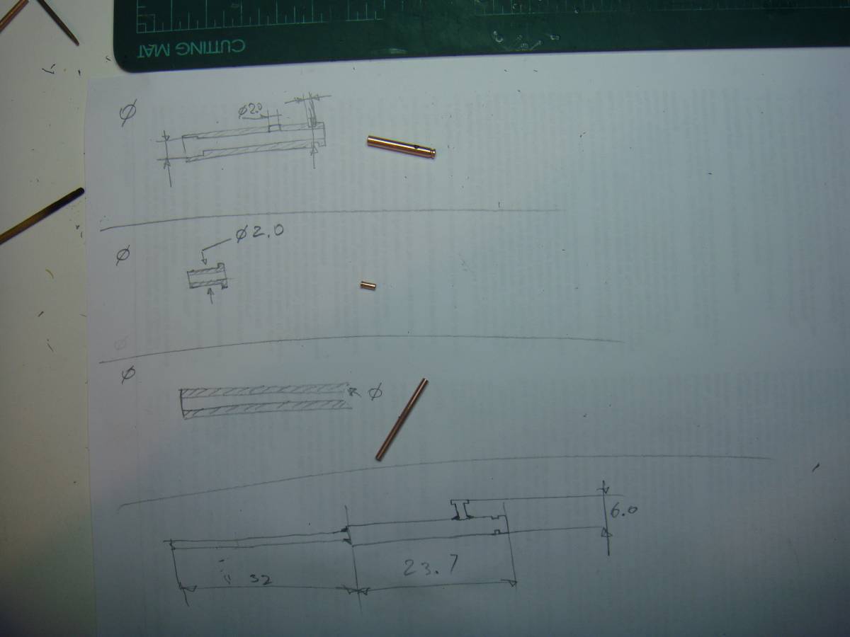
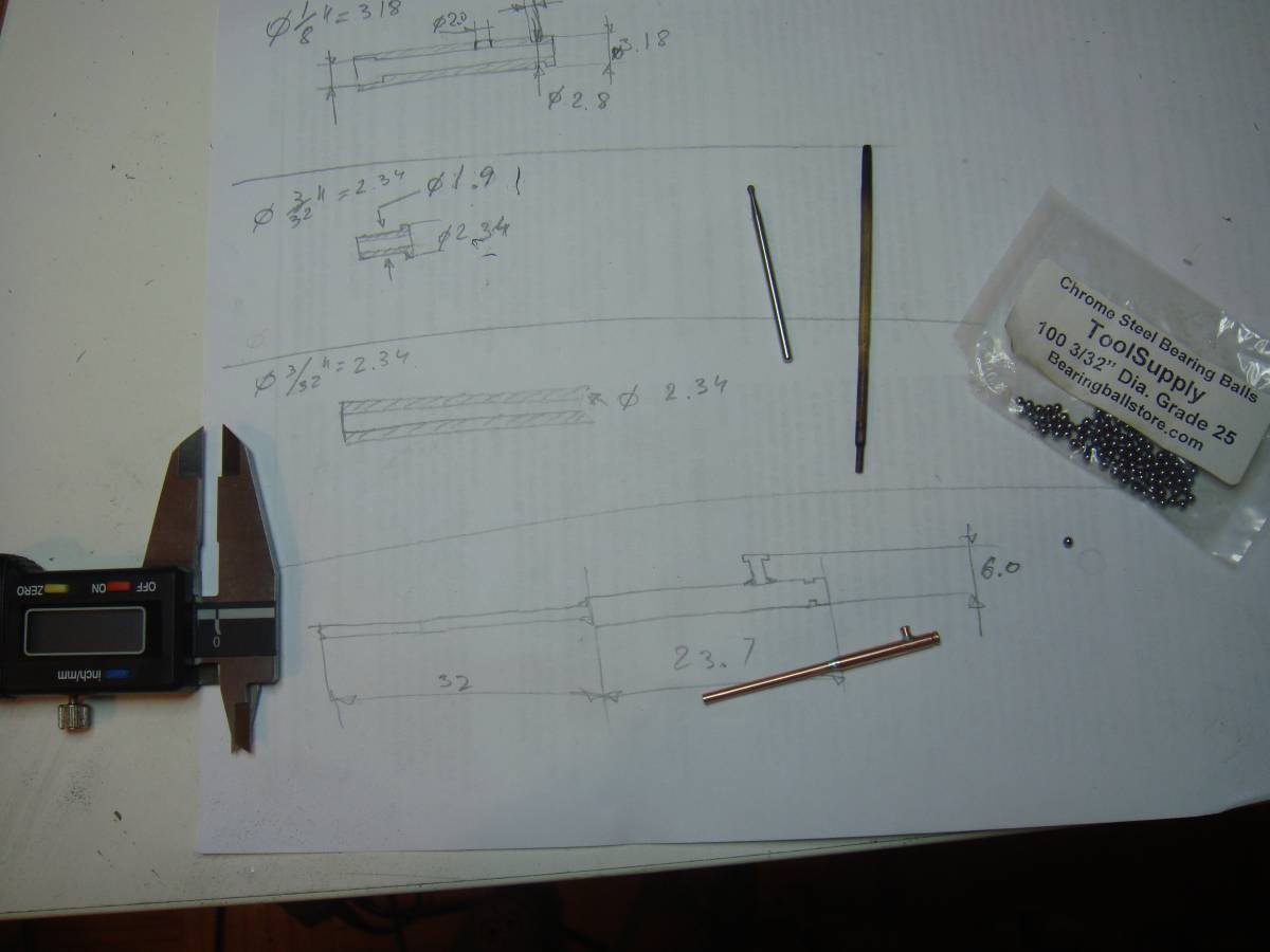
The “pipe”:
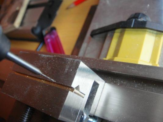
On copper tube 1/8'' (main pipe): grinding out a little groove for the locking bolt

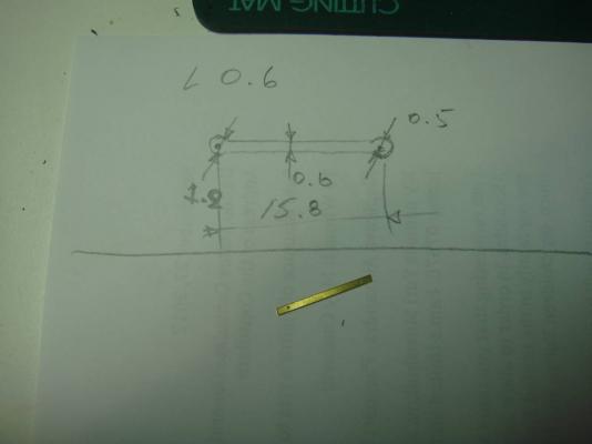
Cutting off to the size (see the sketch below...)
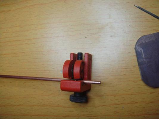
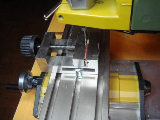
On other side of the 1/8'' main pipe drilling a 2.8mm bore; that would be a place for a ball of lower valve
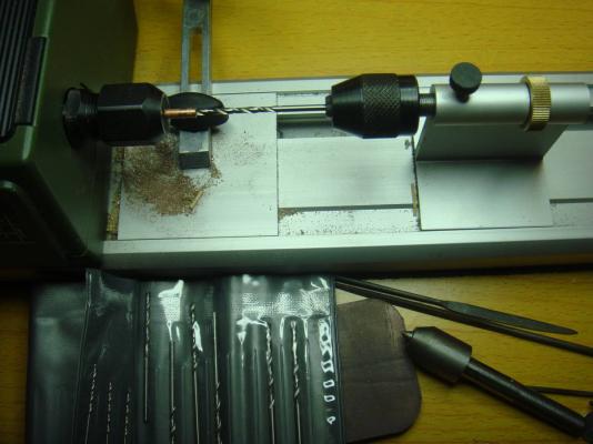
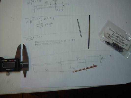
Copper tube 3/32 ""(overflow pipe): Grinding down the desired area up to 1.9mm (see sketch below...)
In the 1/8’’ main pipe: drilling a 1.8 mm bore for the overflow pipe
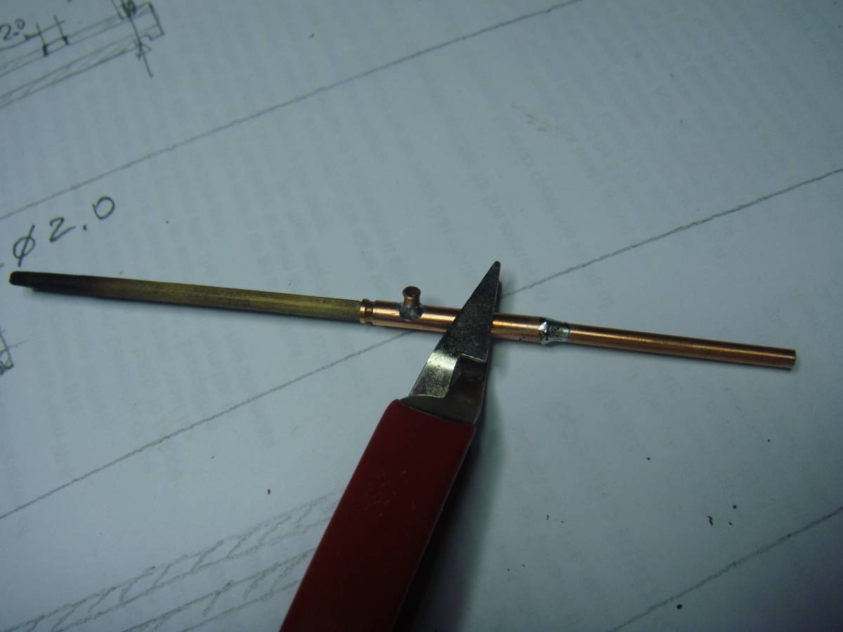
Another piece of 3/32" tube and all 3 parts for pump pipe are ready
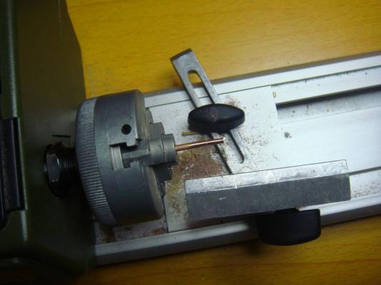
Soldering all together using simple conductor
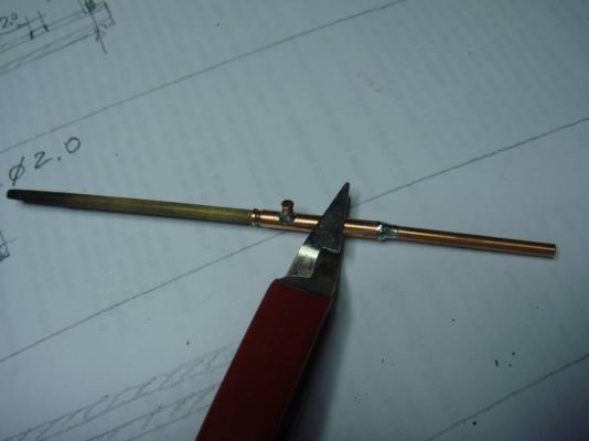
Reseating the soldering of lower and upper pipes with help of 3/32" diamond sphere
-
-
The head:
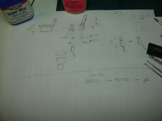
0.3 mm brass piece: bending, drilling, grinding out a support of handle (have no photo, but looks like everything is clear from the sketch)
Soldering the 3/16'' tube (with bore for 00-90 thread) to the head cover.
Inserting the 5/32'' tube into
Fluting and cutting the threads for the locking bolt
First fitting
Soldering the support of a handler
Chopping, grinding out, trying on
- Dan Vadas and Cap'n Rat Fink
-
 2
2
-
-
to be continued....
and well... how i can fix a typo on topic header?

-
The base:
Soldering 5/32'' tube to the base bed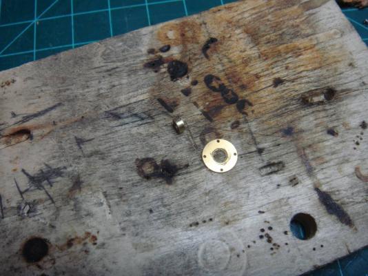

-
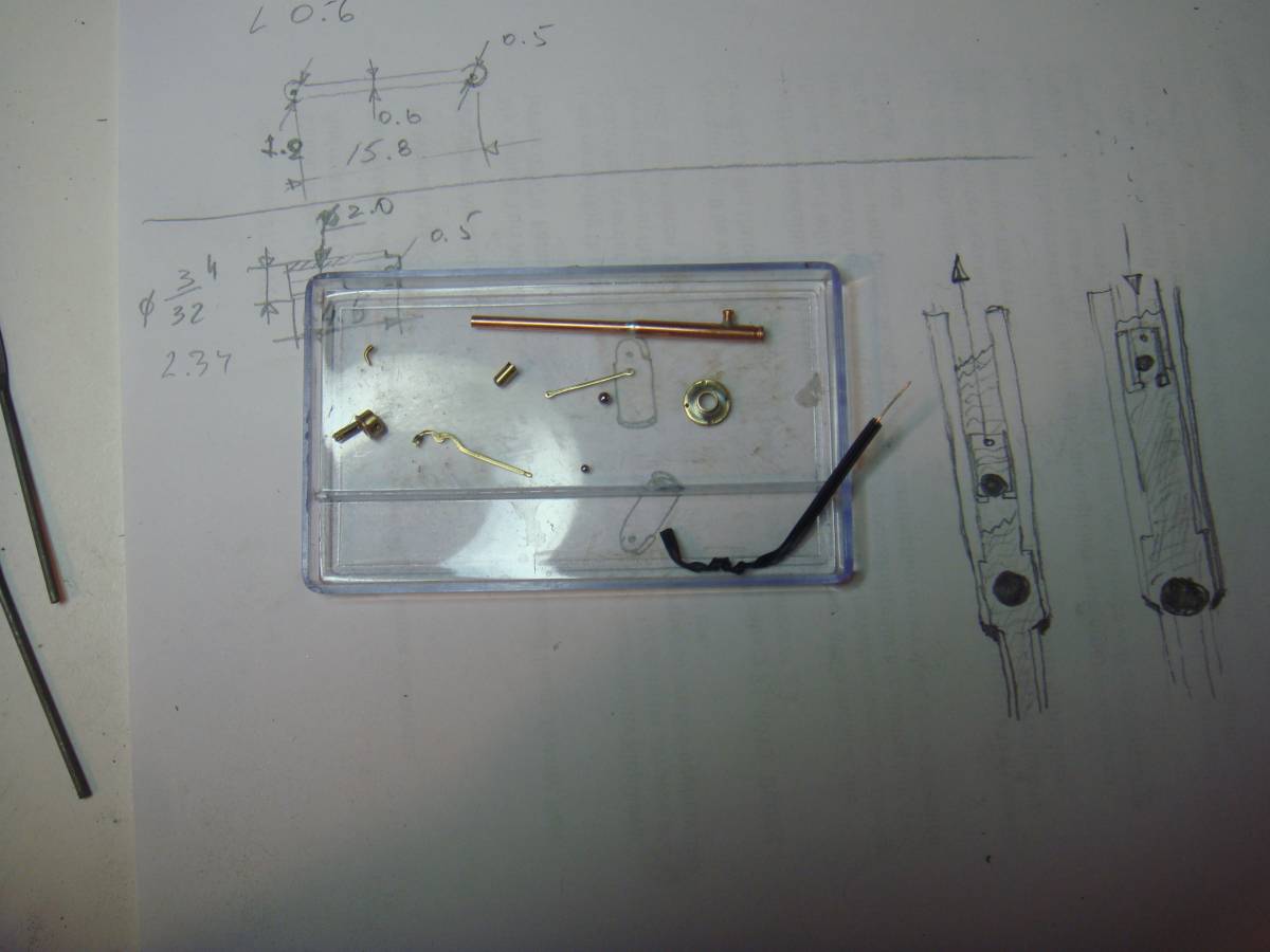
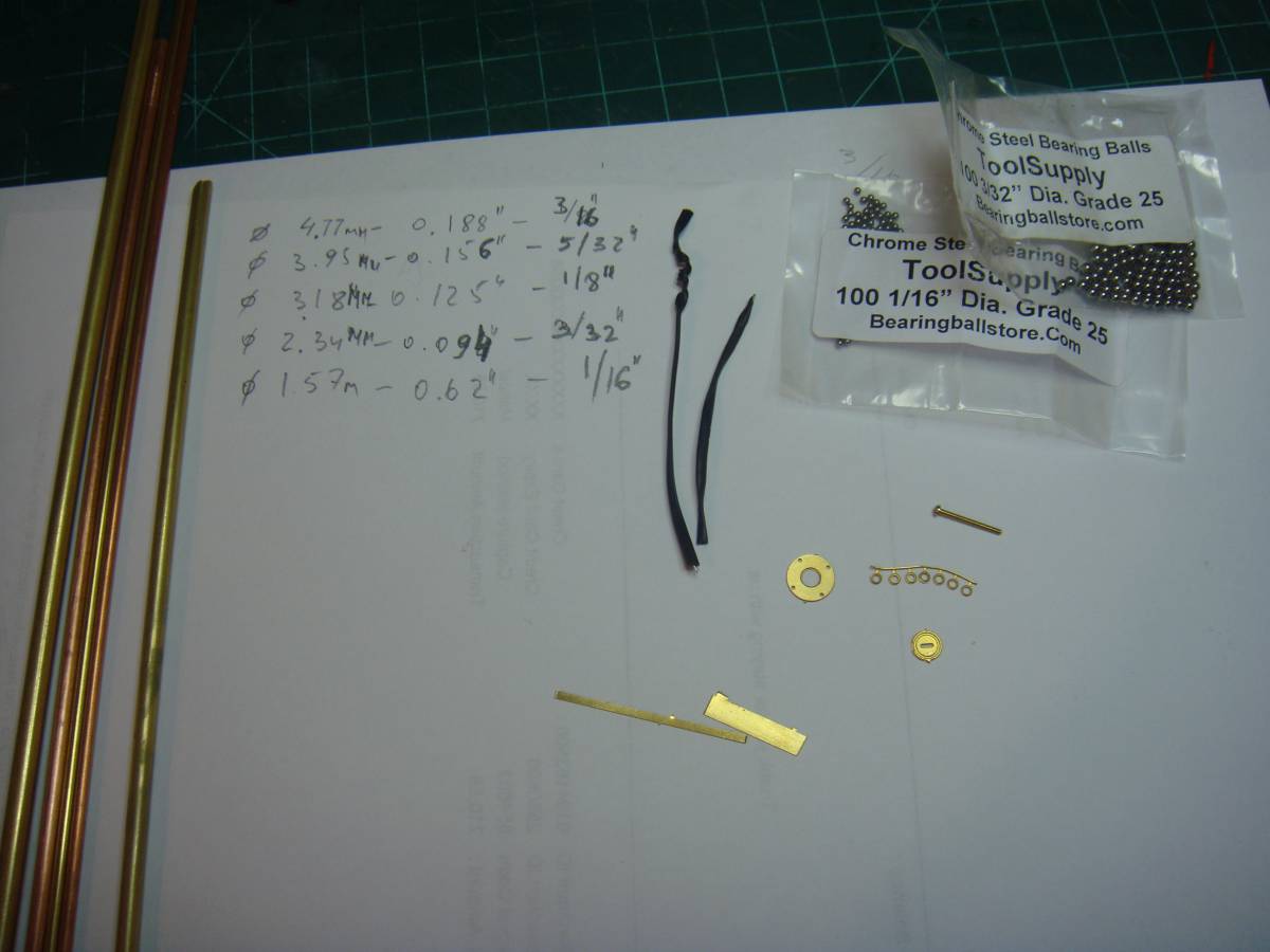
Materials:
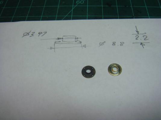
The real implementation forces to change pump proportions for a little: follow up to standard set of copper (and brass) tubes: 3/16'', 5/32'', 1/8'', 3/32'' and 1/16''.

The chosen tube set is giving a great opportunity - the inner diameter of a tube corresponds to the outside diameter of the tube оf next number – the tube move -in and -out into each other as closely as possible.
Designed etched details on brass 0.6mm thick were good for nothing – I had no inexperience, and did not add 20% of the thickness to the edges of small parts, so they were eaten to be useless ... Nevertheless head cover and the base bed are ok. But the remaining parts – handle, support and stock - should be done by hands.
And yes!!!: a metal wire from the package of bread and brass washer with 1.5 mm inner diameter.
Also I have to say: an idea to make the pump “working” came while of assembling: that was happen that I have steel balls with 3/32’’ and 1/16’’ diameters (I bought them to simulate charges for 24’ carronades and 6' guns, respectively)
Oops!! One more thing: a 00-90 bolt
-
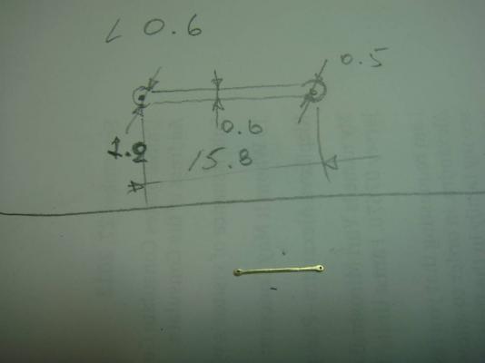
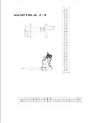
The "working" copper bilge-pump with two valves and removable head in 1:64 scale
Important note:
There is no guarantee for historical conformity
The pump's sketch was designed based on reseach:
«Ships' bilge pumps: a history of their development, 1500-1900» Thomas J. Oertling
-
Many people asked me to share how i build it.
So i have no excuses do not do it....
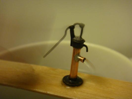
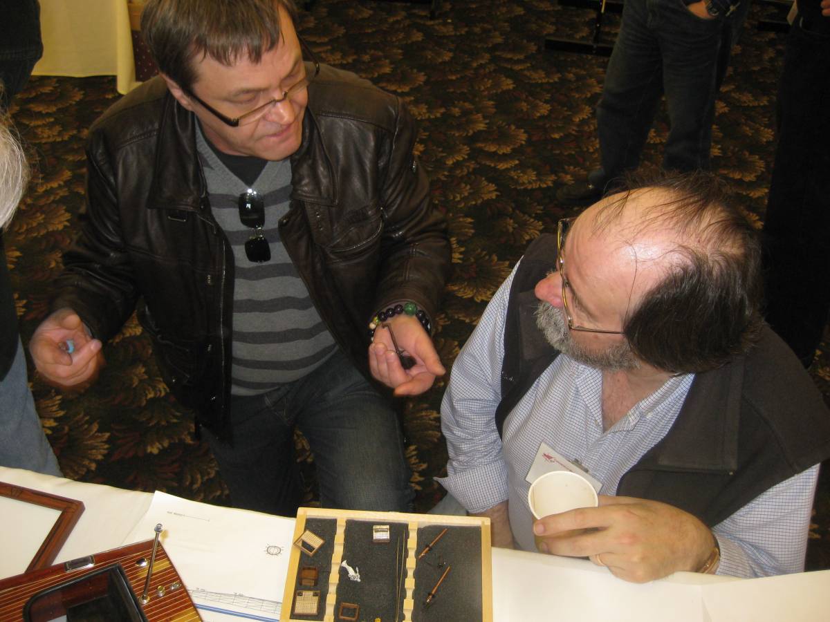
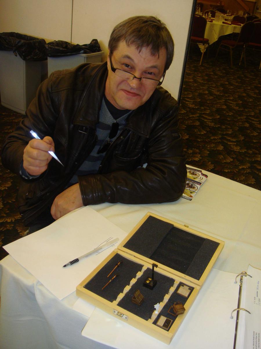
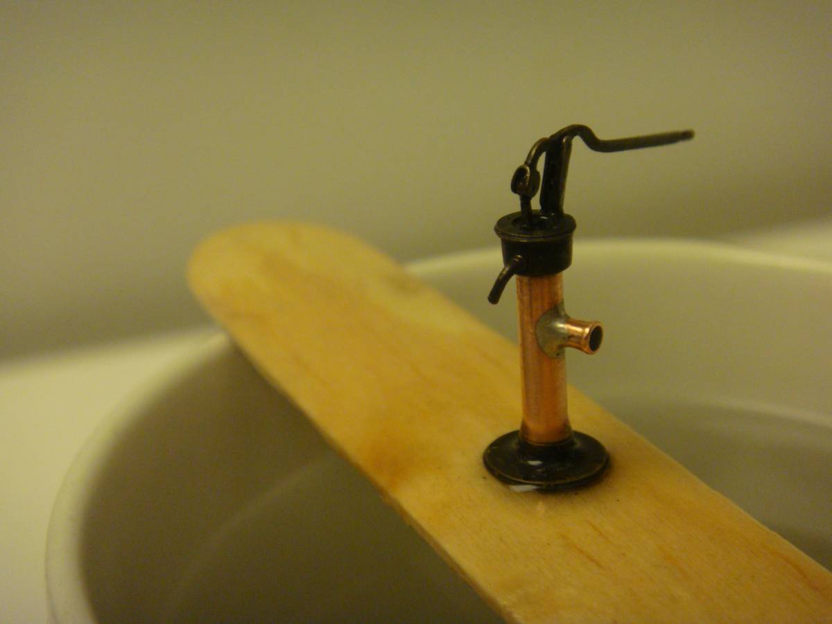
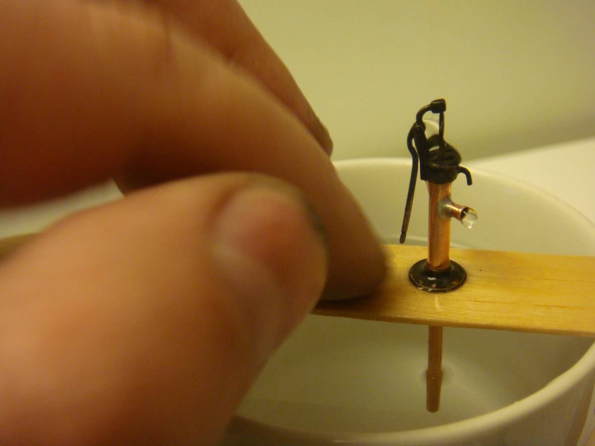


Working copper bilge-pump 1820, 1:64 scale
in Discussion for a Ship's Deck Furniture, Guns, boats and other Fittings
Posted
Thank you Chuck