Richard Dunn
-
Posts
530 -
Joined
-
Last visited
Content Type
Profiles
Forums
Gallery
Events
Everything posted by Richard Dunn
-
 Dr PR does a single led create much heat? like if I make resin printed light fitting for them would it melt the resin?
- 454 replies
-
- 2
-

-
- Union Steamship Company
- Stepcraft 840
- (and 3 more)
-
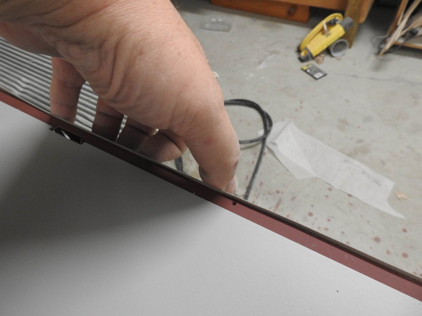
These frames get glued onto 2mm clear so plenty of support and need to keep the back flat and smooth, that's why I chose to build on plate
- 454 replies
-
- 2
-
-
- Union Steamship Company
- Stepcraft 840
- (and 3 more)
-
I have done some tweaks to the exposure times and got a pretty descent print on the Phrozen test, tomorrow I will try some more windows. Not the best shot, Wife is getting a new macro lens next week so that will be good

- 454 replies
-
- 3
-
-
- Union Steamship Company
- Stepcraft 840
- (and 3 more)
-
OK so I have done a test and I am underexposed quite a bit
- 454 replies
-
- 2
-
-
- Union Steamship Company
- Stepcraft 840
- (and 3 more)
-
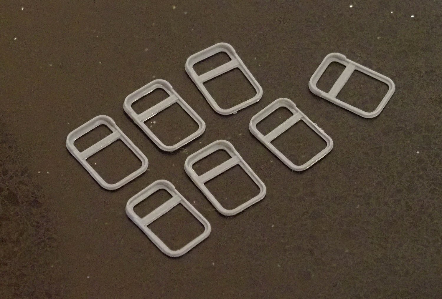
I would like to know what people think of these main windows, compared to photo, keep in mind there are 180 of these to make and they are only 11 x 16mm Getting some collapse of the vertical walls, I don't want to go any thicker though so might need to play with resin settings,
- 454 replies
-
- 5
-
-
- Union Steamship Company
- Stepcraft 840
- (and 3 more)
-
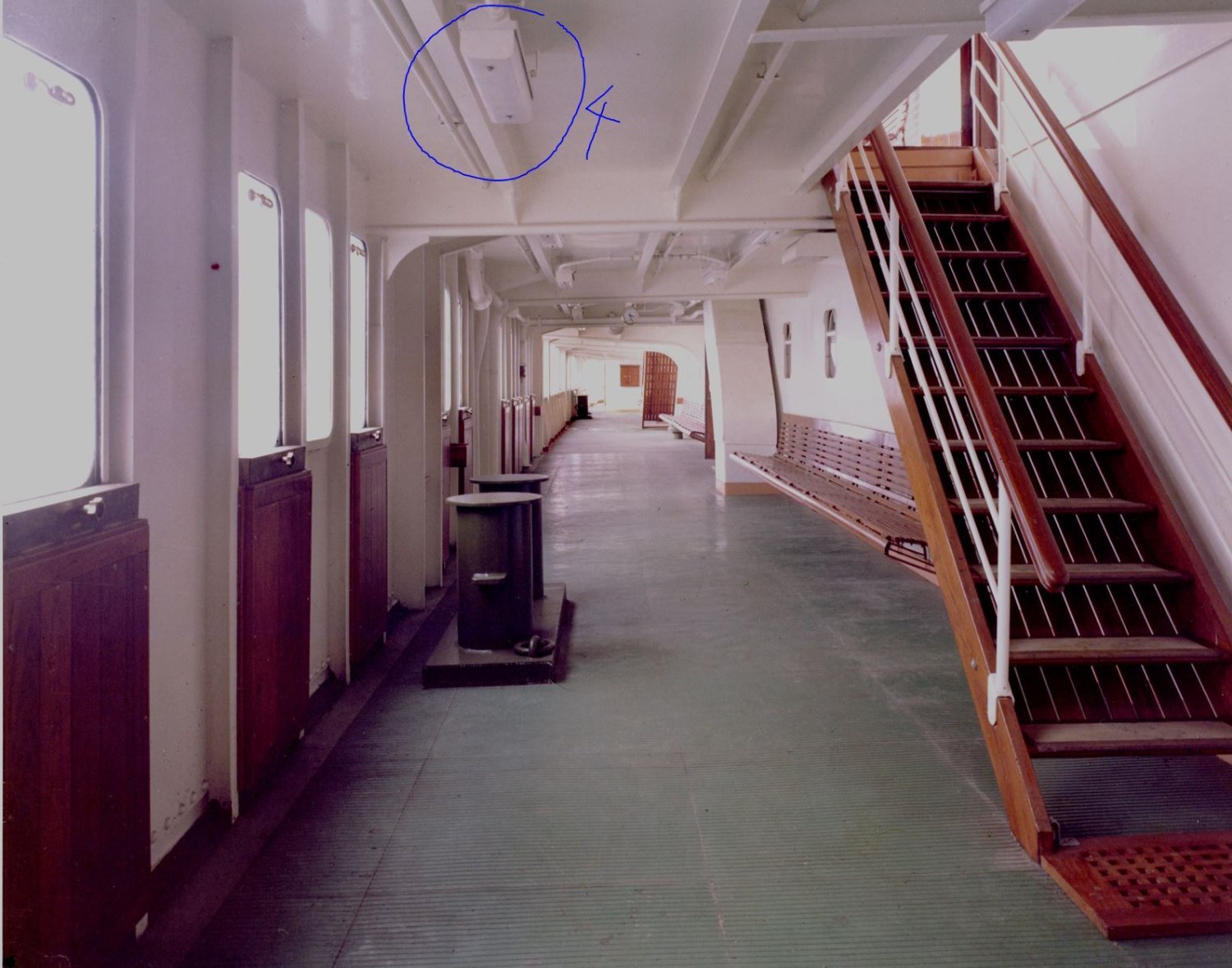
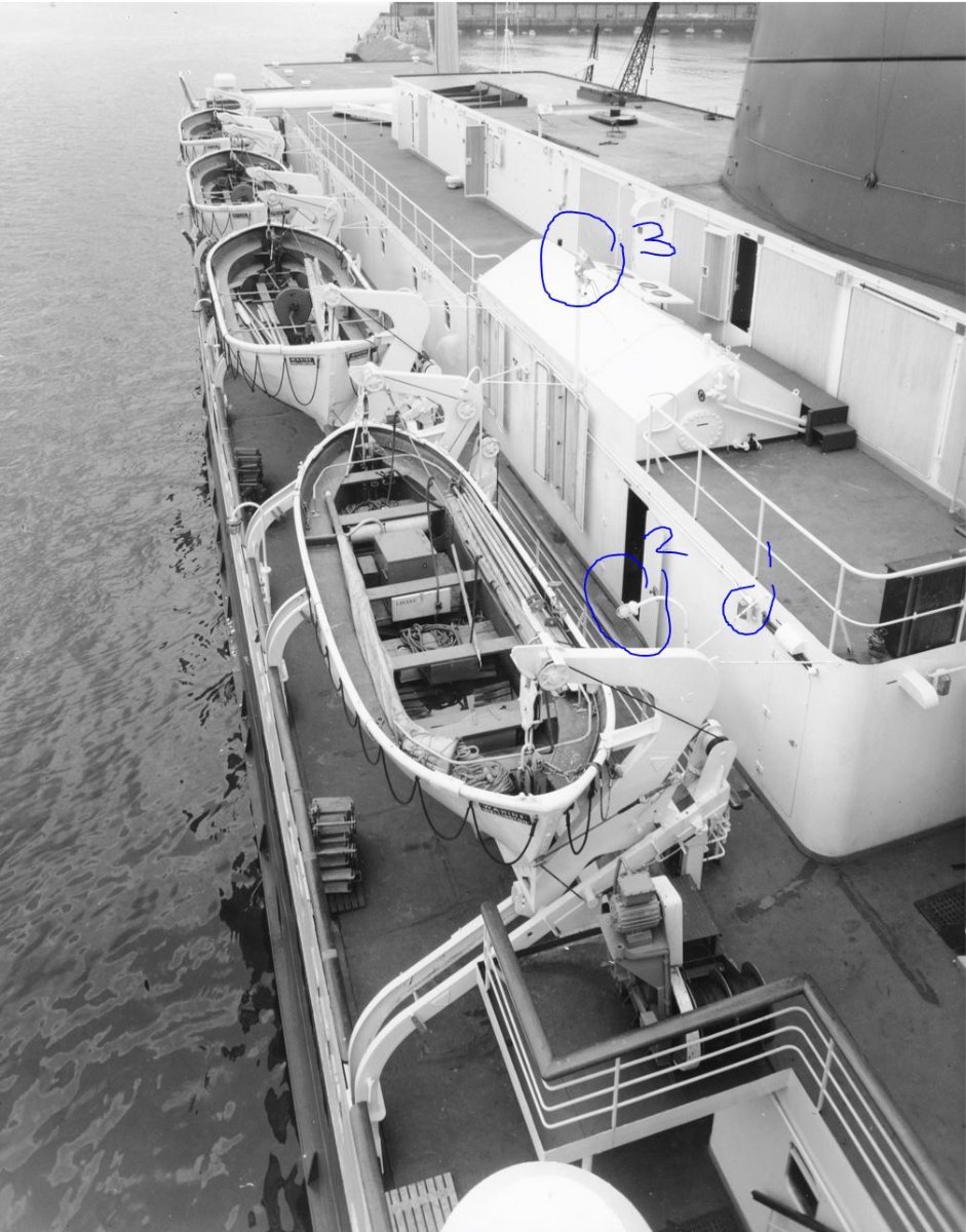
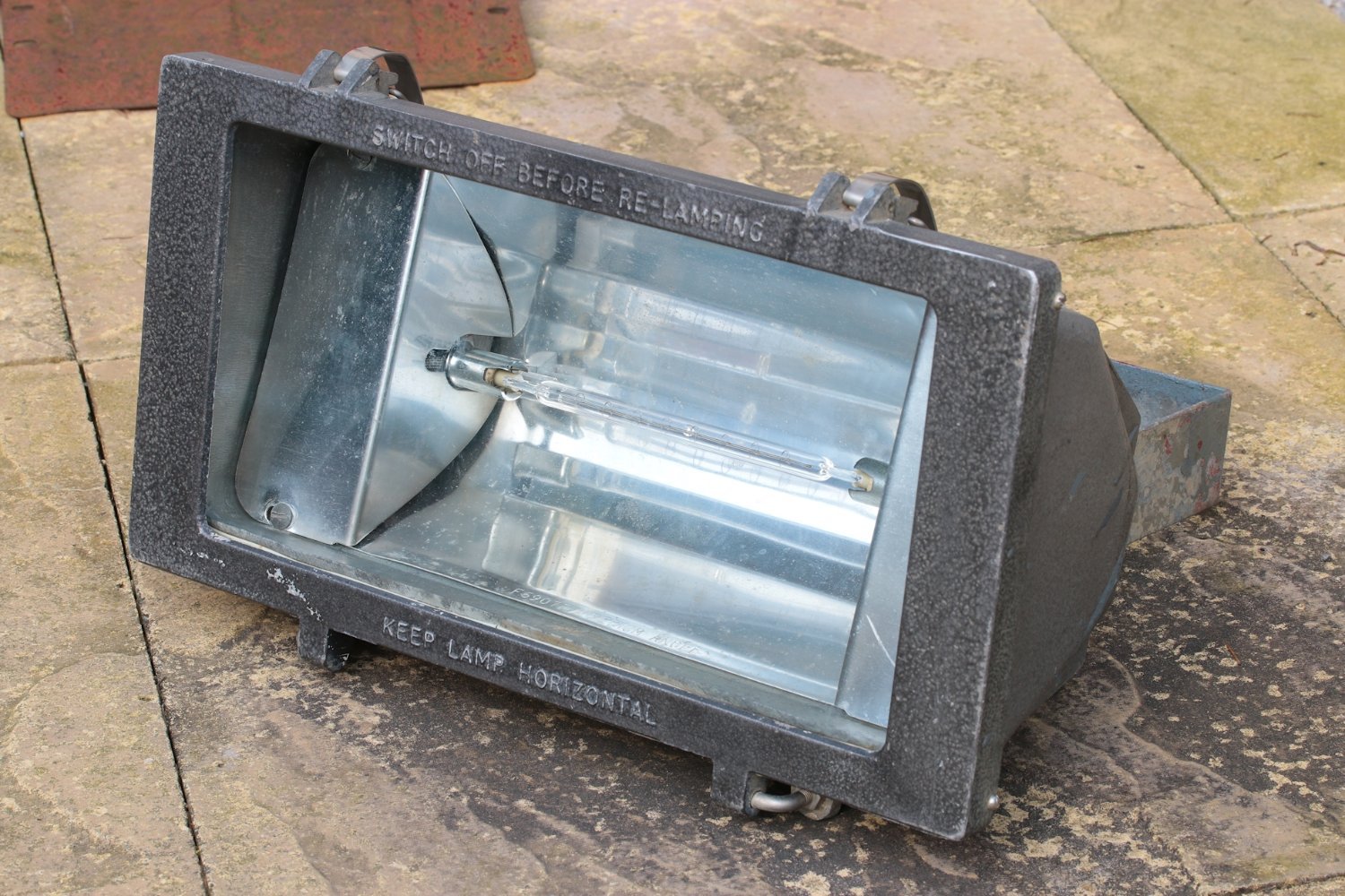
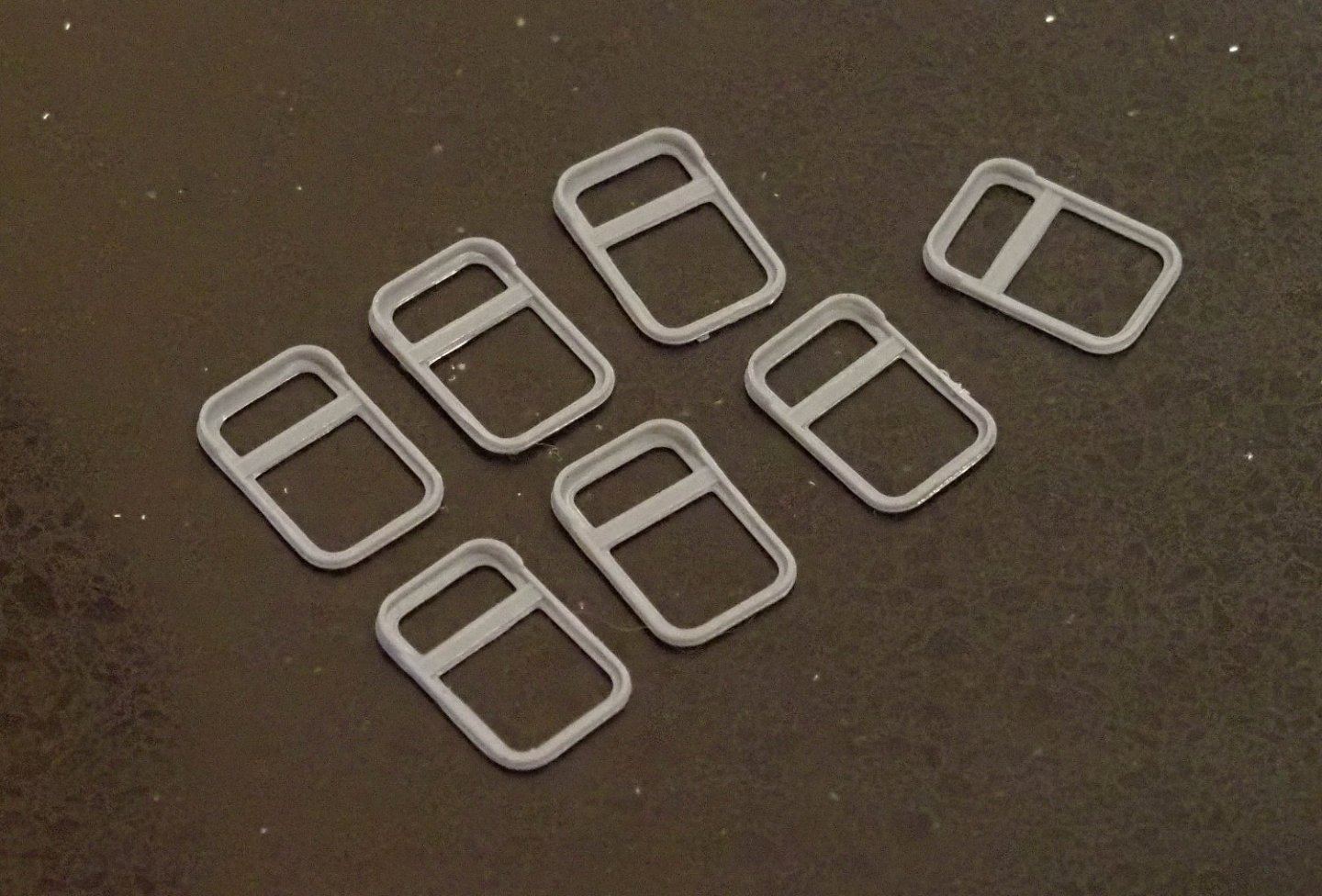
This is giving me some things to think about... darn it I don't like thinking after I have finished work. The main thing is I need to design a system so I can bore the holes in the shell to allow it all to be hooked up and at the same time be able to change an LED bulb if it goes. the other thing to is I need to be able to dim the lights, not with a knob or anything but to the right level to match the ship. Just so you guys can see what the lighting is going to be and how insane actually am. So we have decklights on walls, flouro tubes under decks and halogen spotlights on funnel. Here we see 3 types Type 3 there is only 6 of on whole ship but the brightest by far (halogens). Type 2 are only over lifeboats and can be left as leds are by default Type 1 is the most common Type 4 is the flouros in mounts under decks, and yes all that framing is going in under see decks. putting this up as well in case it interests anyone, but this shows how much data I have, very rare case indeed. Arrangement of lighting circuits, A deck, captain's, navigation bridge and wheelhouse top.TIF Arrangement of lighting circuits, A deck, captain's, navigation bridge and wheelhouse top.TIF


- 454 replies
-
- 6
-
-
- Union Steamship Company
- Stepcraft 840
- (and 3 more)
-
I found this pdf online here by Gary Roberts and thought I would share it as it is very handy. LEDLightingForModelShips.pdf
- 454 replies
-
- 2
-
-
- Union Steamship Company
- Stepcraft 840
- (and 3 more)
-
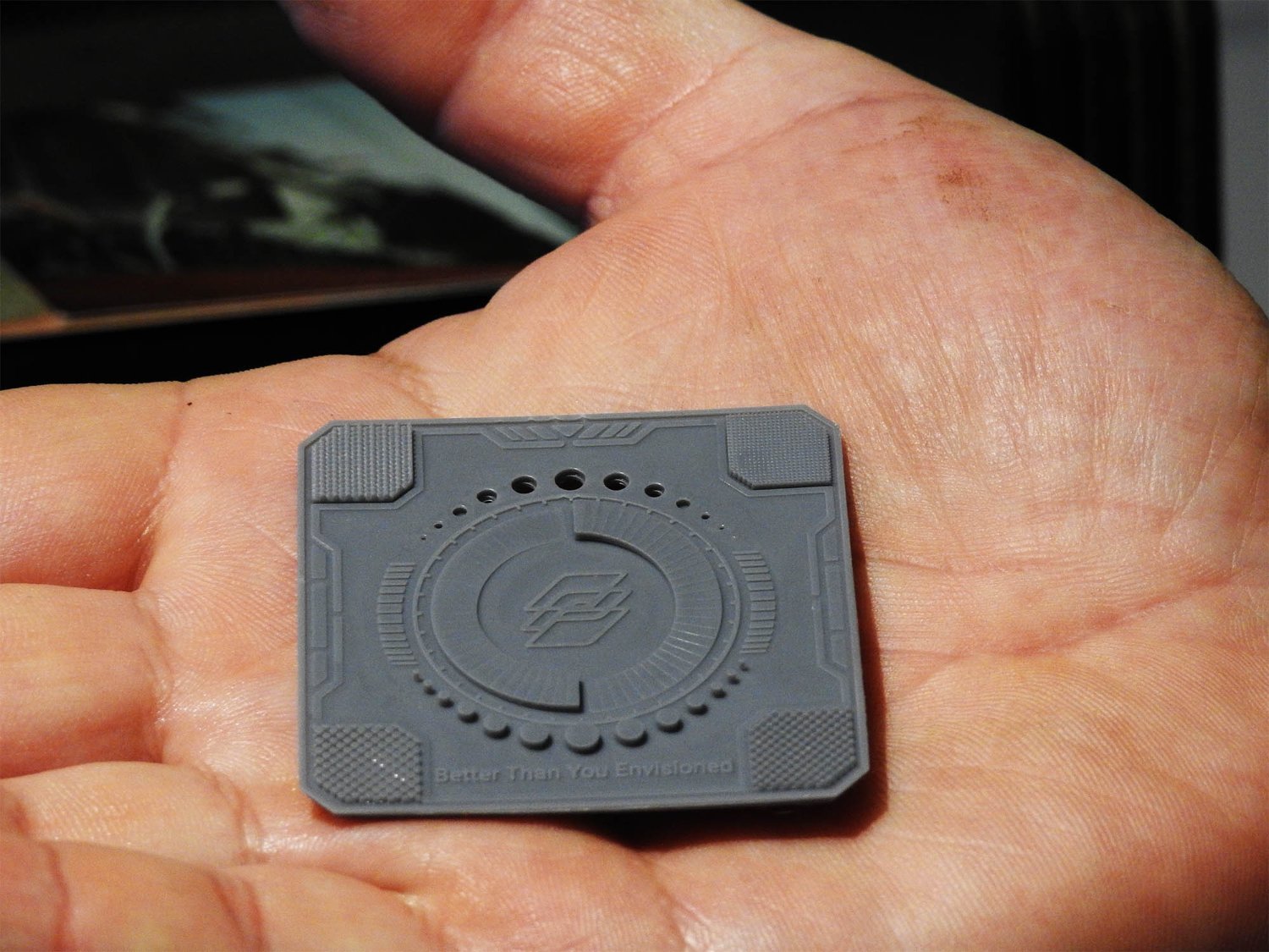
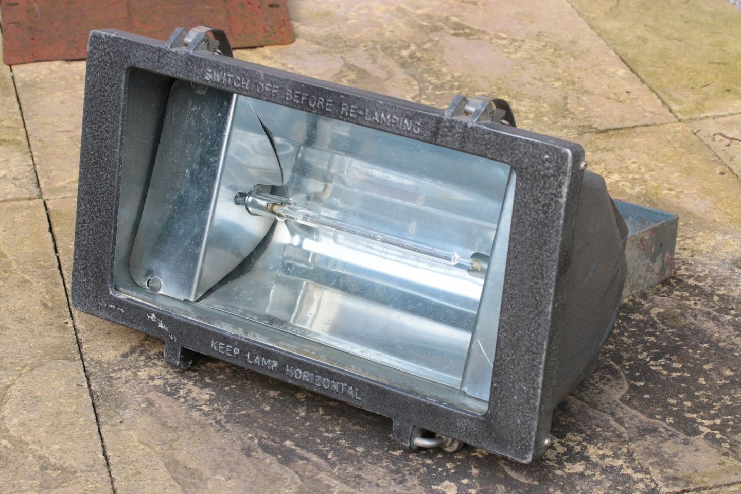
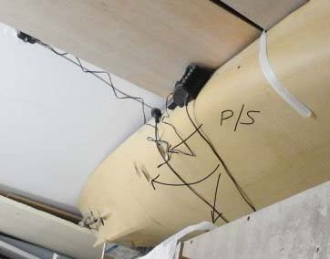
Another question Lights, in particular these light on sides of superstructure. I have small led bulbs for these and I will make the actual fitting from a resin printed model, the lens being clear resin, but in regard to the wiring you will notice they are connected with 25mm conduit, should I fake those only and wire through the back or could I use .8mm copper wire to make conduit and use that to wire lights? Would the wire get hot? and ruin white paint. This ship has a LOT of these lights, I think 250 all up over several decks of course and not all on same circuit, I reckon maybe 20 per circuit Advice?
- 454 replies
-
- 3
-
-
- Union Steamship Company
- Stepcraft 840
- (and 3 more)
-
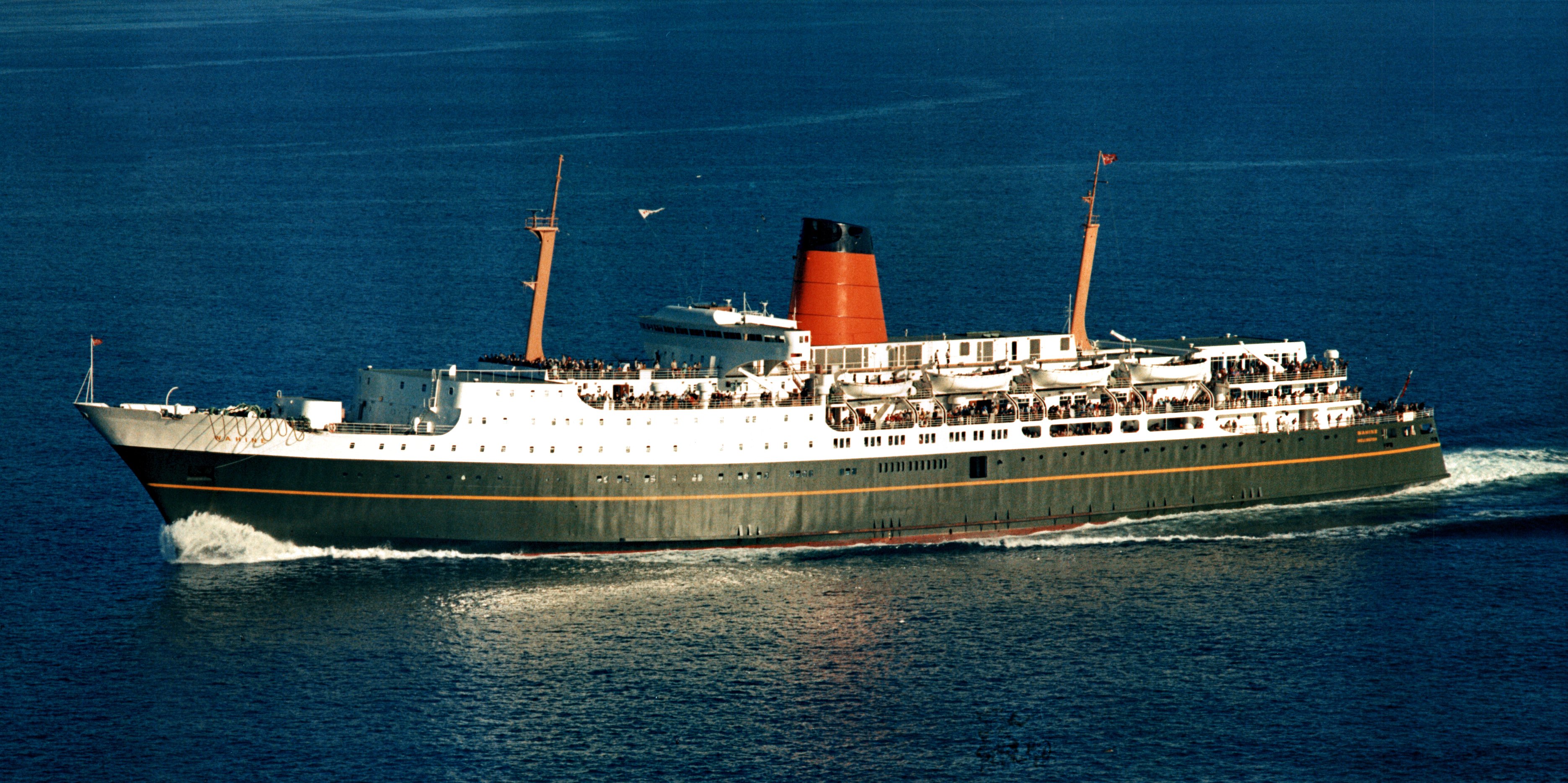
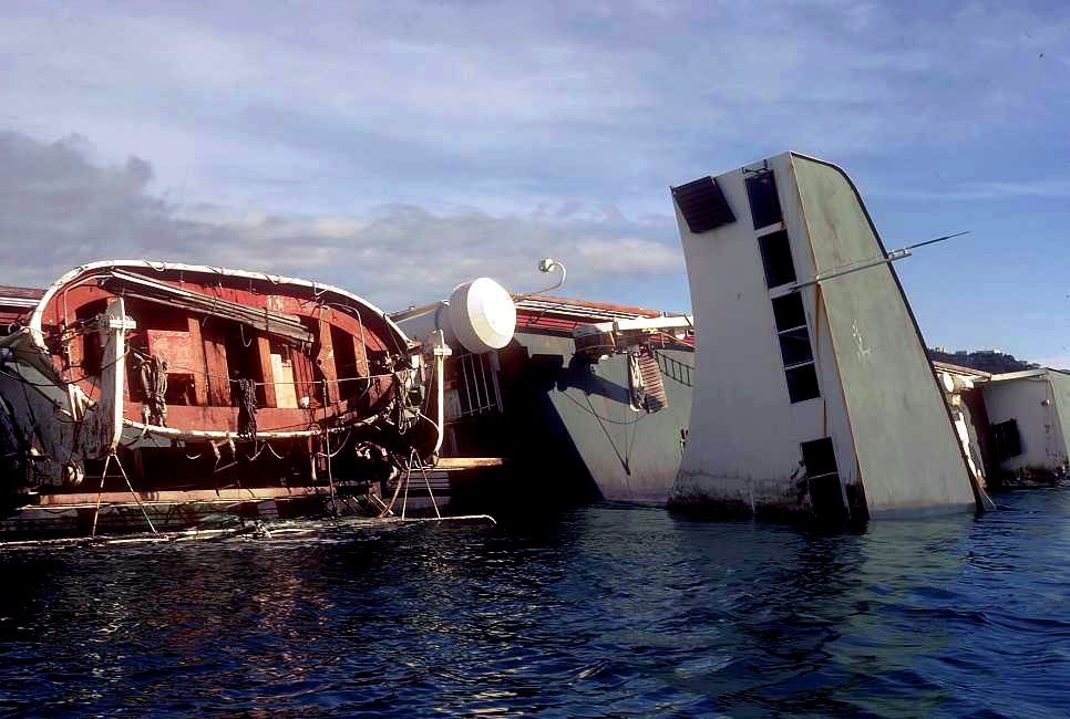
I will look at those, but the deck is a rubber/cork compound and is smooth but it ages really quickly. I have done a lot of plastic kits in my life and am familiar with dry brushing and hand painting weathering techniques but this is on a scale that has large areas of deck I need to cover and in the video below you can see the effect, I am thinking sponges and subtle changes in value. I am using automotive paint but deck can be different as it's being done off ship. The decks however are still primed with single pack acrylic primer at the time of her foundering she was almost due for her 2 year survey as a guide to amount of weathering. Here is a model at 17:10 , the best weathering job I have ever seen and the way the decks are done is SUPERB I want to know how to do this. go to 17: 10 I have soo many images I could show but cant for copyright reasons but this sad shot does show the decking in its worn state.
- 454 replies
-
- 2
-
-
- Union Steamship Company
- Stepcraft 840
- (and 3 more)
-
Thankyou Veszett. And no, at least I hope not. If anyone has some advice or techniques for painting worn rubberised decks like seen above PLEASE share as that is going to be the biggest challenge for painting
- 454 replies
-
- 2
-
-
- Union Steamship Company
- Stepcraft 840
- (and 3 more)
-
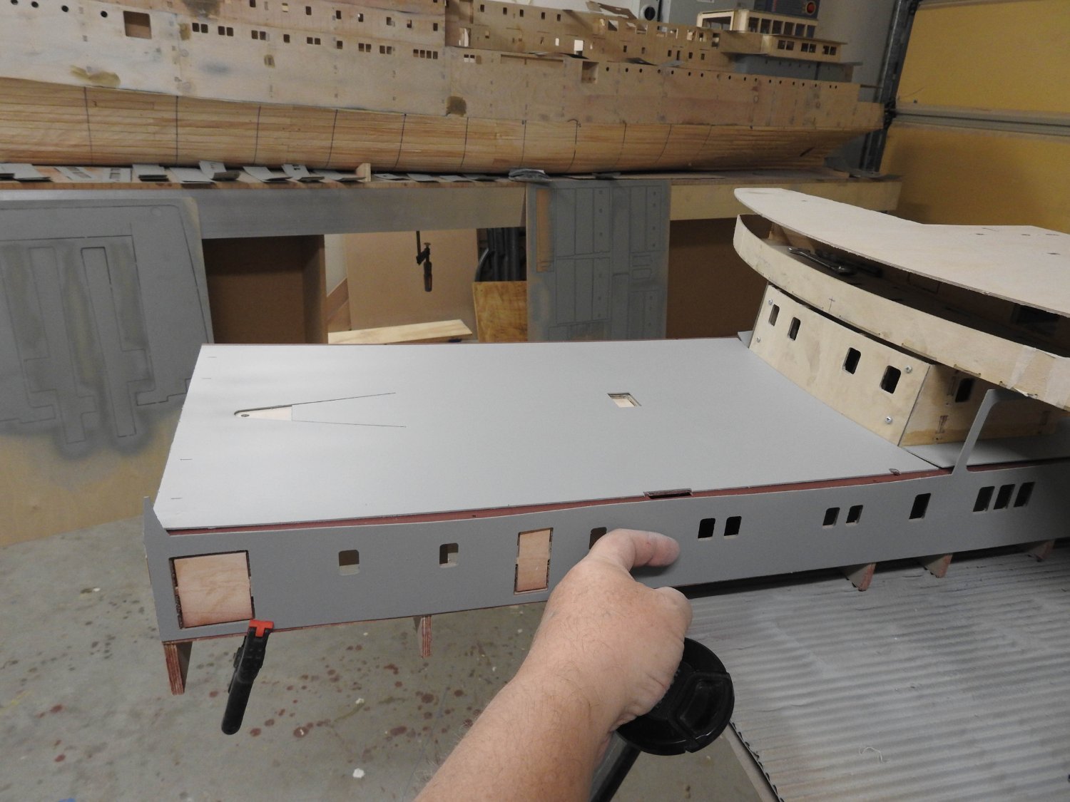
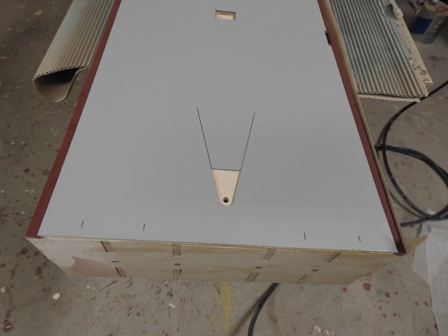
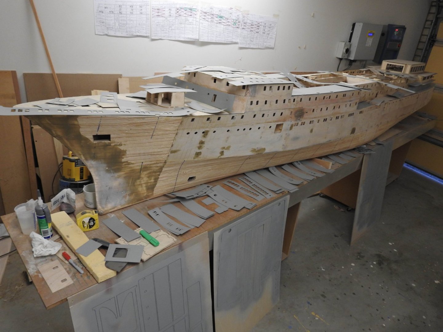
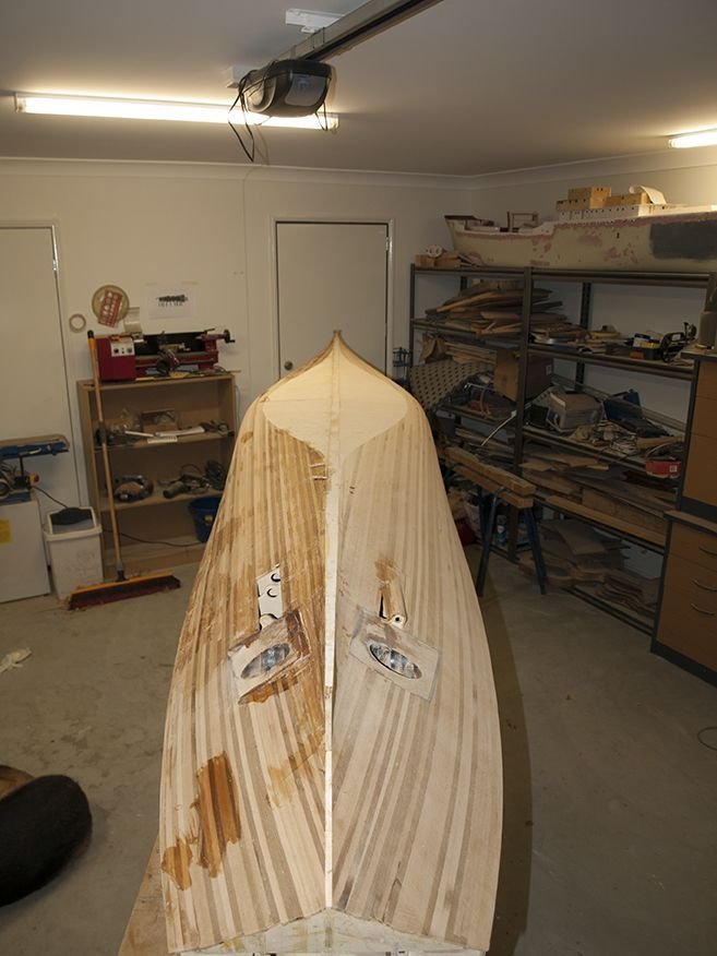
Some pictures of the priming process and how it all comes together. Plates ,plates and more plates. Pic on wall behind is a checklist, red cross being primed, green being tin-canned and ready to install. Working like this means the ply becomes like working with styrene in as far as it is surfaced and paint ready, only the sides of structure that have to have stiffener and framing attached are left, I am unsure if I should just prime it all and remove paint with a 1mm chisel where gluing needs to happen or weather to just paint the whole part once all framing is attached. My gut tells me the first option that way I can paint the surface while flat and paint all the web frames, stiffeners etc and once all glued on I can brush paint the corners where the joint lines are. An example of superstructure side, this will get sliced up where seams go later, just held on of course. Waterway construction, here you can see the upstand formed by the ply, and why the primary grain direction is vertical to strengthen the upstand. the holes are scupper and vent locations Fine CNC work cut with a .5mm cutter to house the mast sides and bulwark stays along the front. The hole in the deck in the mast is a 5mm pin that goes down a full deck and into mast to give it strength as masts have no stays as such The CAD model of this area o you can see better what is what. And the real ship taken from top of funnel.


- 454 replies
-
- 5
-
-
- Union Steamship Company
- Stepcraft 840
- (and 3 more)
-
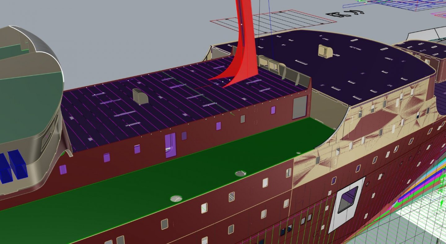
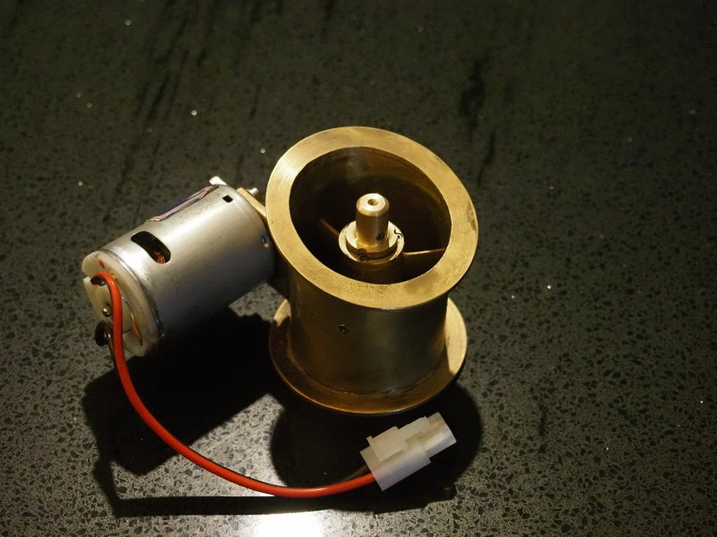
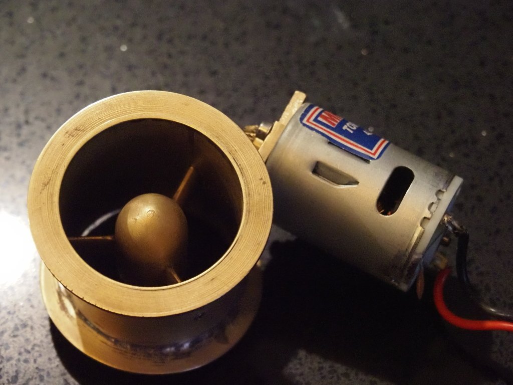
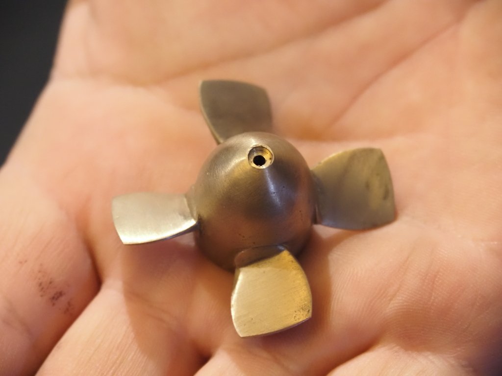
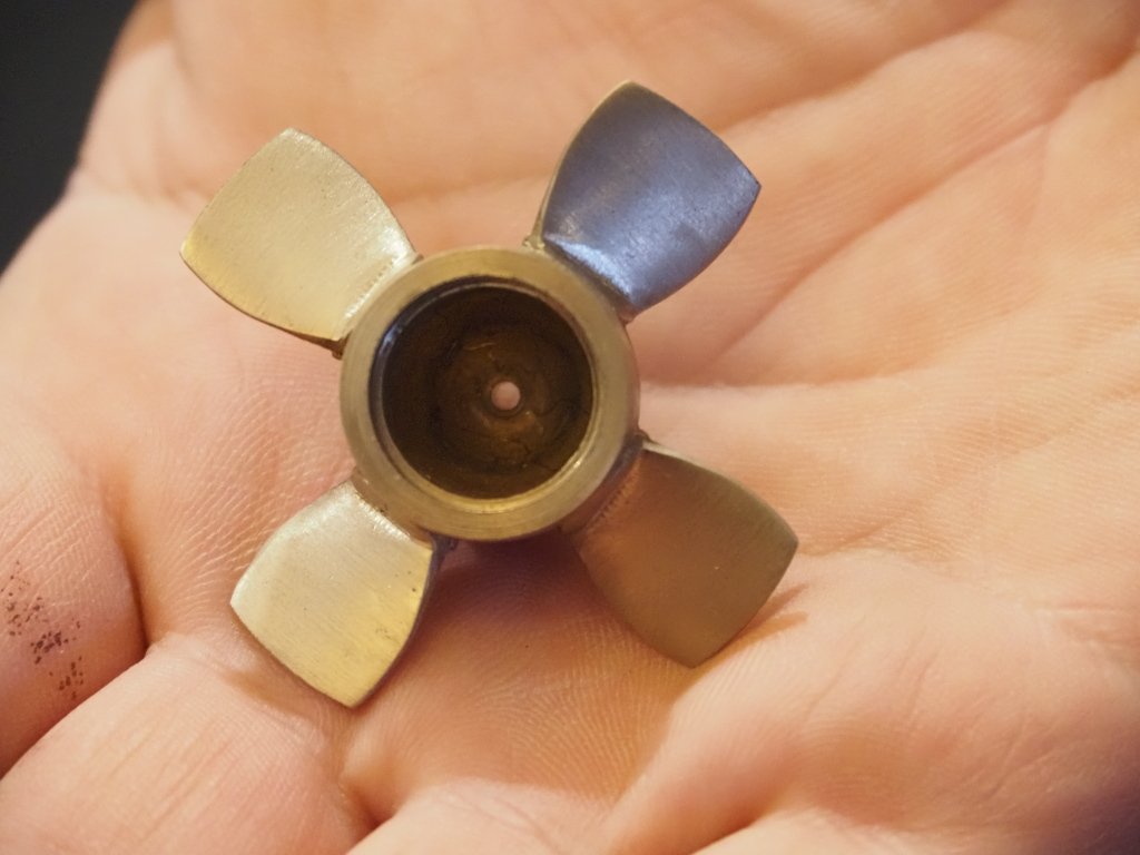
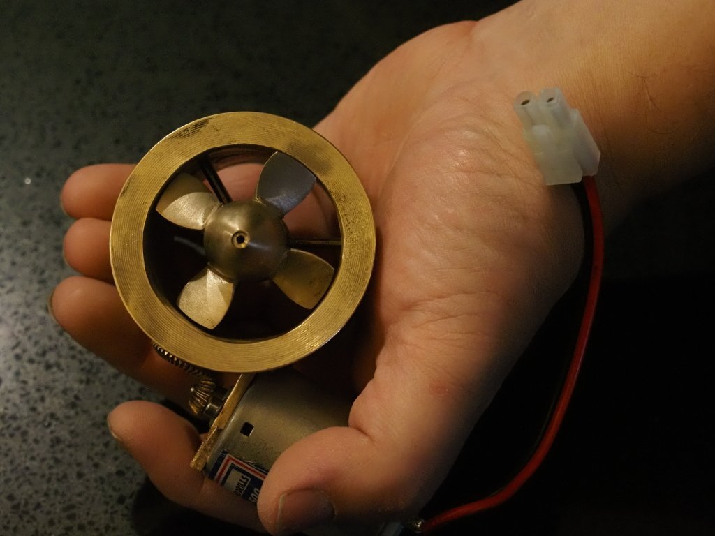
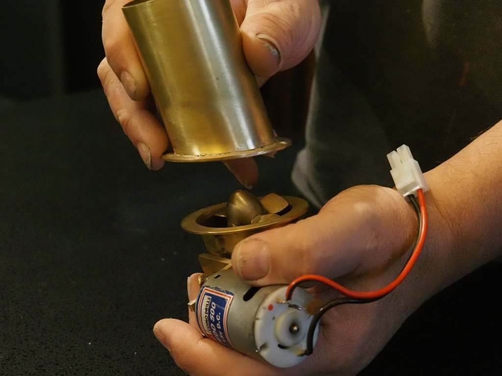
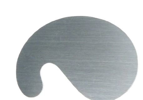
Woohoo Thrusters have arrived for bow and stern. Centre removable section with prop removed to show access cover to gears as well as struts and strut fixing. Other side of boss Prop, notice even the circler disc for the variabl pitch blades are modelled. Prop in place in Tunnel. How the centre section mates to the flange on both sides with a thin rubber gasket( not shown) to seal the tunnel, centre section is held down tight by cradles. All that remains is for tunnels to be fixed into hull and kept back 10mm form skin, faired into hull and the grills soldered into tunnel mouths. The whole unit will then be painted in red oxide except prop as I don't think the prop is painted normally correct me if I am wrong. Thank you Simon Higgins from PropShop you have outdone yourself
- 454 replies
-
- 8
-
-
- Union Steamship Company
- Stepcraft 840
- (and 3 more)
-
I want to recommend this product as well, its industrial grade CA and from what I have seen its superior to the ZAP and other brands I have used, not to mention a lot cheaper due to bottle size, I have had an open 2oz bottle for 2 years and its still as good as new and by god does it stick. https://starbond.com/ I am considering using the medium thick rubberised one for gluing plates to hull as I can hold them in place for 40 seconds and its done. The thin one I have is instant bond, I mean a fraction of a second.
- 454 replies
-
- 2
-
-
- Union Steamship Company
- Stepcraft 840
- (and 3 more)
-
I have figured out why I have an uneasy feeling preventing me from moving on, ,over the last 3 days I have been priming all the plating and superstructure cladding with hi build primer, as was contemplating the tin canning effect an felt it was still too heavy, I have discovered that 3 good coats of high build is enough followed by using a curved cabinet scraper to remove tiny amount between frames, so just a little and others down to the ply but the effect is much more subtle and I am far happier with his now. This is a scraper ,its used to finish wood instead of sandpaper and is sharped by rubbing a burr onto the edge which acts as a hooked cutting edge. In guitar building we use scrapers as the surface does not have clogged pores in the wood, it keeps them nice and open for grain filling prior to varnish, sandpaper fills the pores with tiny fibres of torn wood. many old school craftsman use these still as they can produce shavings when done right, although in this case its paint so .... so right now my job is scrapping, sanding with 240 and applying final primer coats to all the plates on the topsides and superstructure and then once glazing is glued in bonding the plates to the hull for good, then as I get seams happening I can start applying weld beads, this will no doubt take a few weeks but at the end she will look like a grey primed real ship with all the little details of her plate work in place, namely the curtain plates (upstands around deck edges). First things first I have to get the first few plates in EXACTLY the right place, luckily I had the CNC pen in the seams on the play as they were cut but most of it has been sanded off, should have enough points to get it right, I will tape 9 plates together off the model and then place them on with double sided tape and remove and glue as I go This is how it will look as next stage is complete including the darker grey primer over he seams to help me keep track of what is done and what's not.

- 454 replies
-
- 4
-
-
- Union Steamship Company
- Stepcraft 840
- (and 3 more)
-
Already purchased all the profiles I need in bulk, but round or square it will get squashed when rolled over while soft with a fine serrated roller. If Davies Garner bought his Titanic model down here it would melt in a week, not kidding either. It makes model building a little more expensive but we do what we must, .5mm ply 1200 x 1200 is $100 per sheet. I have so far used 10 sheets of .5mm and 6 sheets of 2mm.
- 454 replies
-
- 4
-
-
- Union Steamship Company
- Stepcraft 840
- (and 3 more)
-
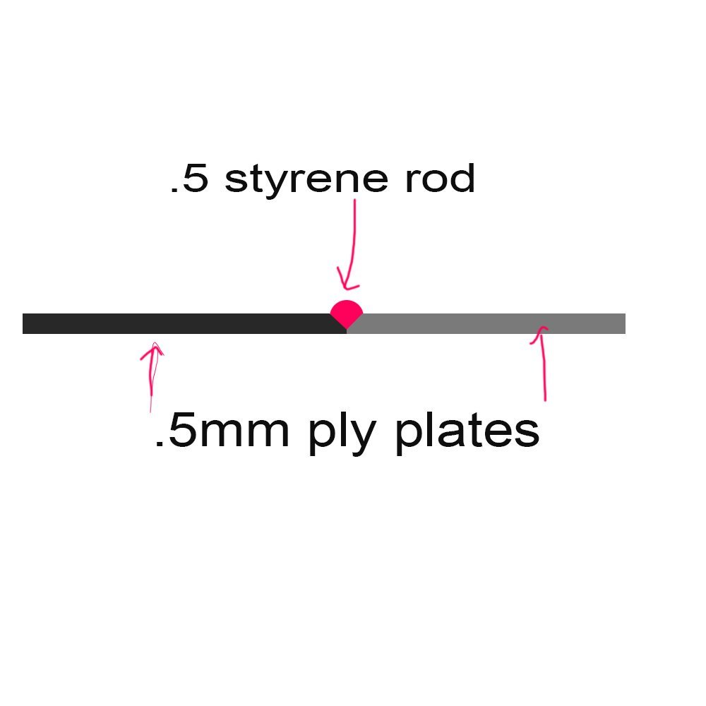
Thanks guys but this is not about making and gluing plates to the hull its about gluing the .5mm styrene rod into the groove in the .5mm ply. While people bought it up though I will write a bit about styrene panels as it stands In Northern Australia, IT does NOT work and it's a massive waste of time, I envy you fellows who have cooler climates but for us the glue simply lets go when heated up and the styrene deforms and pulls away or goes brittle, I had a previous model I was building have this happen and pulled it all off again, this is exactly why I use .5mm ply and not styrene. Its not something you would think of if you don't have 30-40 degree temps to worry about. I actually bought a whole pack of styrene, meaning 50 sheets of 900mm x 1200 mm years ago for this model and have since given it away. The only thing robust enough is wood on ply or vice versa and epoxy or in some cases aliphatic (Titebond). I appreciate the help on that but I have already had experience with plates and even considered metal plating but again because of the temps the expansion becomes an issue. I should point out I am a furniture builder by trade and although I stopped many years ago I have had lots experience with laminating tops with contact glue the tops made commercially use a industrial grade contact (usually red or yellowin colour) not the stuff you buy at hardware stores and its applied very thinly with sprayguns but even that will let go if heated enough, like leaving it in a hot garage. Here is an example below, notice the deck peeled back on aft superstructure on model on rack in background
- 454 replies
-
- 6
-
-
- Union Steamship Company
- Stepcraft 840
- (and 3 more)
-
To get back on track, I find myself at a milestone and paralysed by fear. I am ready to start the plating of the superstructure and hull but for some some strange reason I can't bring myself to start gluing them to model , I am worried I might have missed something maybe. It's a weird thing but I think once I do start I will move quickly as it will transform the model as all the plates are pre primed in grey and once glued on weld beads will be glued into edges and rolled in. I need to experiment with a glue to bond .5mm styrene rod into the v groove.. I am open to suggestions for this as this is something I know you guys will all have done. if I use styrene glue it will soften the rod and enable it to be rolled with fine serrated roller to get the weld bead look at the same time as pushing it into the grove nicely and of course then primed with airbrush ready for top-coating. Another idea that springs to mind is to soften rod and roll into place and once hardened again run a runny Super glue along bead to bond it in? Once rolled it will flatten the rod and widen it a bit, and by varying pressure a bit I can get the varying width look a bit.
- 454 replies
-
- 3
-
-
- Union Steamship Company
- Stepcraft 840
- (and 3 more)
-
Totally agree, we have 1 phone we use for emergencies as you said (wifes), and I do work in high tech jobs as well, VR and Computer graphics/animation and all that, my wife is a programmer. I do have to say though that we both taught Game Dev at 1st year UNI level for several years and took 236 students through this 4 year course and in that time the damage to most students communication ability we witnessed due to texting and phones is just scary. We even used to get reports written with large amounts of texting shorthand in it ,needless it was a fail as literacy was a key component.
- 454 replies
-
- 5
-

-
- Union Steamship Company
- Stepcraft 840
- (and 3 more)
-
Hmmm you could be right, personally I wish Likes were not a thing, I prefer to actually communicate...but then I am old school.
- 454 replies
-
- 3
-
-
- Union Steamship Company
- Stepcraft 840
- (and 3 more)
-
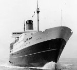
Every few months I search the web for new photos that might have surfaced that people have posted of the ship, Isn't it annoying when people do because they think it will interest people and yet when you contact them they ignore you...I mean we modellers have more use than most for such images... It drives me nuts!.
- 454 replies
-
- 2
-
-
- Union Steamship Company
- Stepcraft 840
- (and 3 more)
-
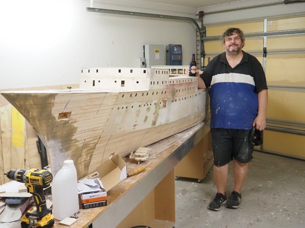
Having a beer on the Wahine. Here is a shot I took for my father because I have just found my favourite beer in Australia after 20 years! but it puts the size in perspective.
- 454 replies
-
- 16
-
-

-
- Union Steamship Company
- Stepcraft 840
- (and 3 more)
-
I had not worked it out yet, I have worked out the following though total weight 195kgs Model weight 60-70kgs Batteries 28.5kgs x 2 = 57kgs Tank weight over2 tanks 36.5 kgs in trim Free ballast lead ingots 32 kgs The Bow tank is a massive 25.6 L/kgs and is an entire section between bulkheads, however the stern trim tank is only 11L as it is centreline based and has to fit between the prop shafts, I cant see any way of making it bigger and as I write this I realise I can make it bigger by stepping the tank out over the shafts once above them as long as tank can be removed if needed to get to shafts. Guys how far from motors is ok to avoid interference for the RC gear and speed controllers? Motors are in own compartment defined by Bulkheads up to waterline.
- 454 replies
-
- 2
-
-
-
- Union Steamship Company
- Stepcraft 840
- (and 3 more)
-
So after some research and advice from pump people I have arrived at this arrangement, I have 2 trim ballast tanks in the bow and stern of about 8 Litres each (not sure yet) but they will fill via seacock in bottom of hull of 10mm diameter and are controlled by electric ball valves. The inlets will be using the turbo alternator intakes in real ship as they have large enough openings and also grates over them to filter water and being within double bottom are nice and low down. The pumps are to be used to empty the tanks only, I was going to get 4 pumps and pump water in but hey what's the point, a 10mm hose will fill 4 litres in a short enough period and with the seacock being 150mm underwater at start it will have enough pressure to fill quickly, even with no pressure really. The pumps are pressure controlled so when the discharge seacock is opened it will activate the pump and pump out the tank. So basically each tanks has 2 electric valves and one pump in its arrangement. This is the valve at the shell. https://www.baccarastore.com.au/1/2-1-BSP-UPVC-Electric-Actuated-Ball-Valve-2-Wires-with-MO-and-Visual-Indicator And this is the pump. http://www.seaflo.com/en-us/product/detail/601.html Any thoughts or warnings?
- 454 replies
-
- 6
-
-
- Union Steamship Company
- Stepcraft 840
- (and 3 more)
-
If I did and in areas where I might need to around lateral thrusters I use a carving gouge and a guitar makers palm plane used for carving violins etc, in fact I used that to do most of hull as it really hacks away the wood. Finished up with disc sander on a grinder.
- 454 replies
-
- 4
-
-
- Union Steamship Company
- Stepcraft 840
- (and 3 more)