HOLIDAY DONATION DRIVE - SUPPORT MSW - DO YOUR PART TO KEEP THIS GREAT FORUM GOING! (Only 20 donations so far - C'mon guys!)
×
Richard Dunn
-
Posts
529 -
Joined
-
Last visited
Content Type
Profiles
Forums
Gallery
Events
Everything posted by Richard Dunn
-
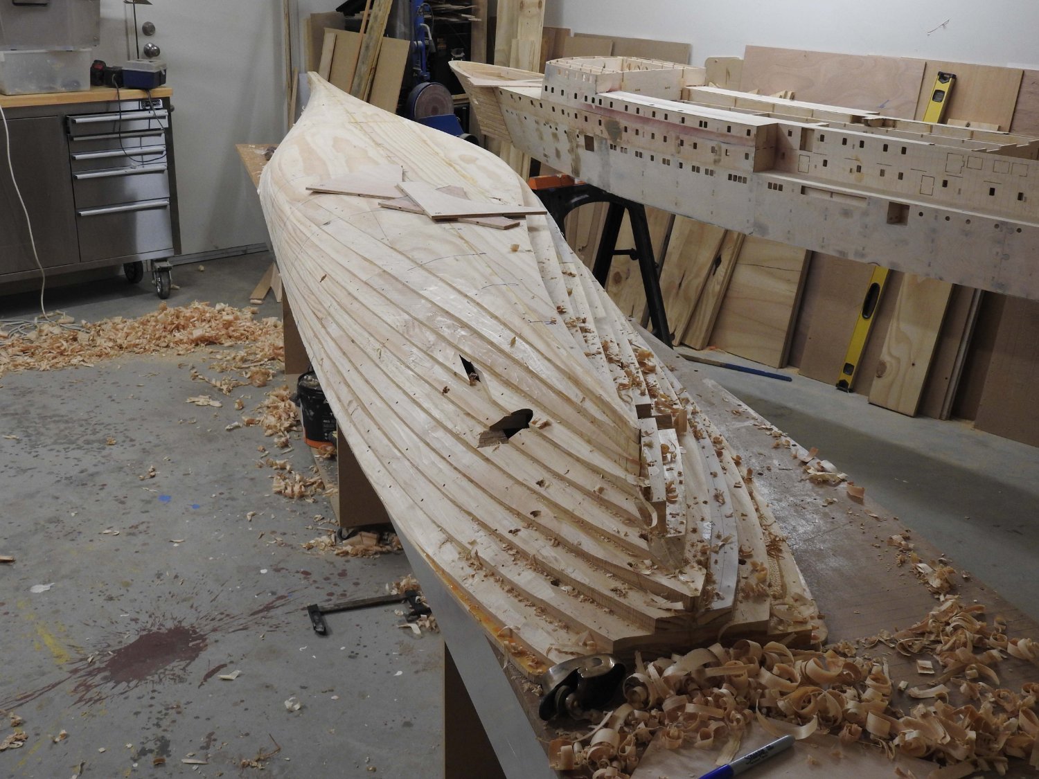
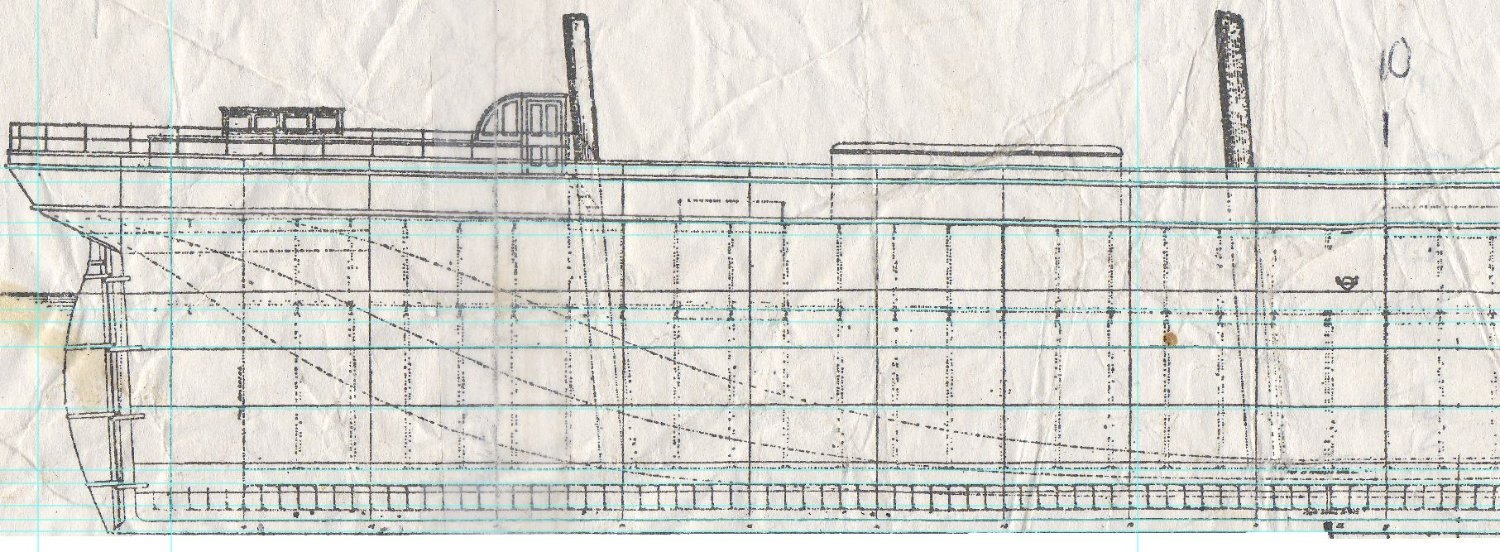
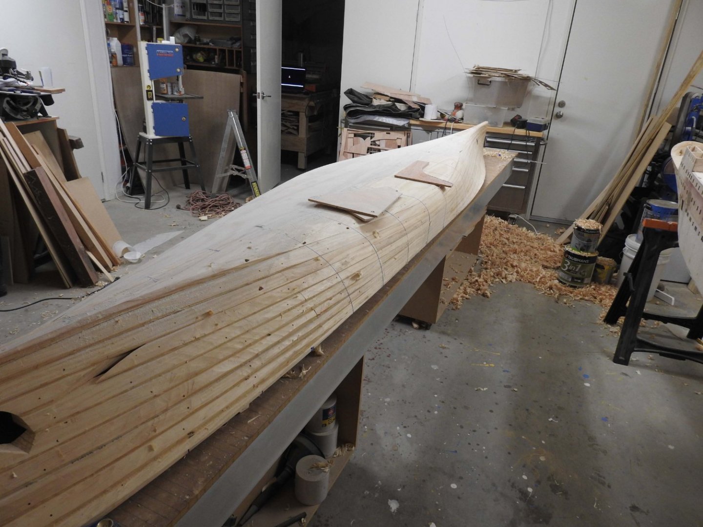
 Ian I have thought long and hard about the benefits of carving the inside vs leaving it stepped, I have come to the decision to leave it stepped as long as its light enough to turn and work on my own, currently I can lift one end of the hull with one finger and lift and turn it with ease, I think it's about 8-9kgs. The thickness does not change if carved or not but to answer your question, the overlap of the planks is 16mm with the bottom flatter areas about 25mm but its not constant as it changes gradually (see image 16 & 17 on page one you can see the overlap marked on patterns). The thinnest part is at the other edge of the very bottom plank due to the rise of floor, the bottom plank is only 11mm thick at edge and 18.7mm full thickness at keel so the solution is to attach beams to the inside of the bottom at the level of the second plank , this will counter any tendancy for the flat of bottom to warp or cup over the midship portion of the model as well as provide extra strength for the batteries etc to sit on I may glass the bottom inside as well. I really wish I had thought of this technique of using multiple parts for each layer years ago, the use of timber is so efficient and so little wood was needed to make this, it's far more efficient than the Kirby technique which still relies on full length planks. if I had had to get planks for this hull full length and full half breadth the timber, even pine was going to cost about $2000 as the wide boards are so expensive and needed to be dressed externally by a joiner as I don't have the machinery to go that wide. This was built with standard dressed timber from Bunnings. Incidentally the whole carved part is underwater except top 20mm and sheer of course but by looking at this mass and you can see the displaced weight of 195kgs hence pumping ballast trim tanks.
- 454 replies
-
- 3
-

-
- Union Steamship Company
- Stepcraft 840
- (and 3 more)
-
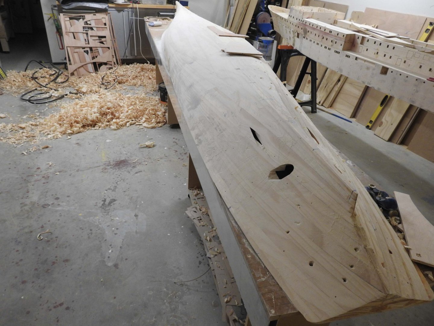
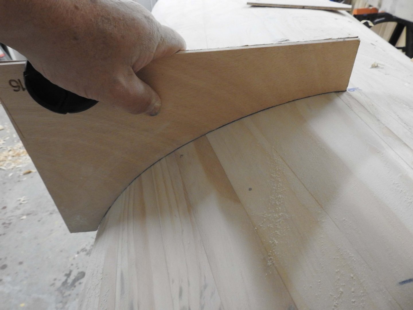
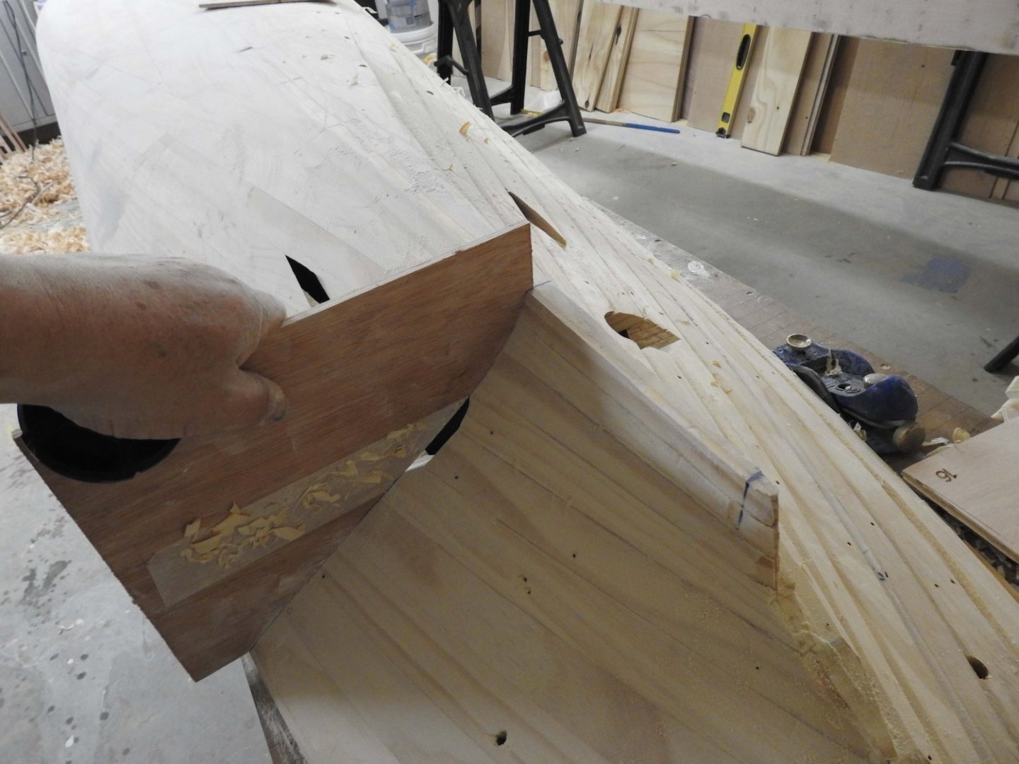
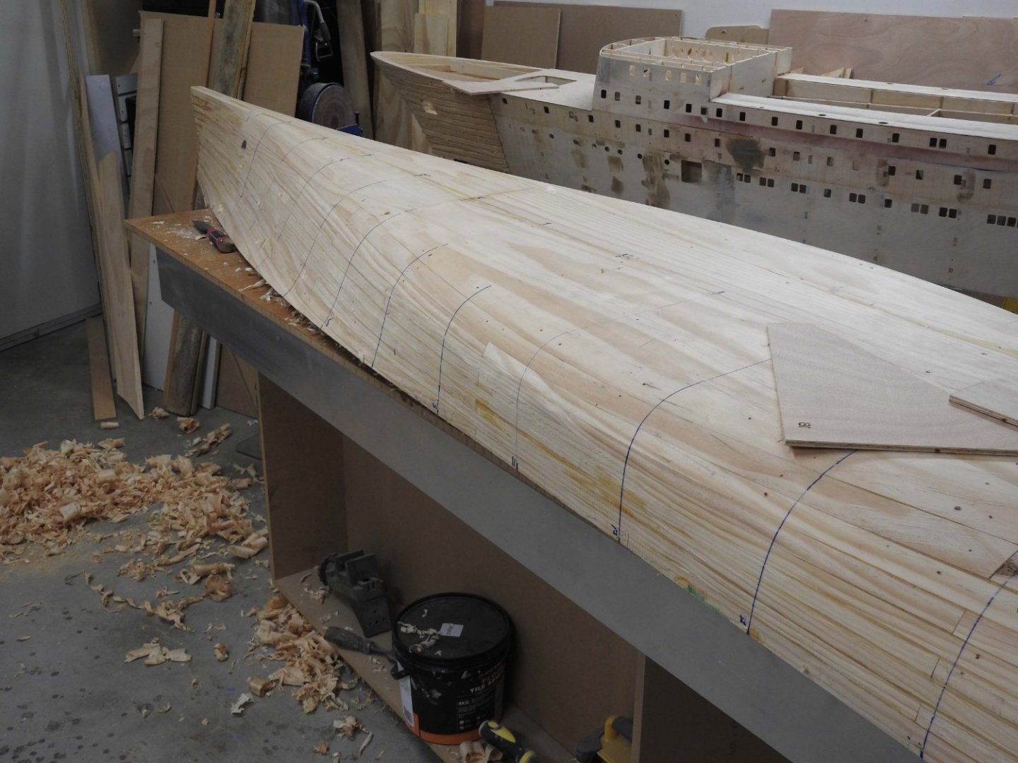
Hull roughed out and 60% of one side sanded and filled ready for glass. Template accuracy. Actual templates are cut on CNC from plans

- 454 replies
-
- 11
-

-
-
- Union Steamship Company
- Stepcraft 840
- (and 3 more)
-
Exactly like that, thank you, so the term was diaphragm pump, now I will find a smaller version, thankyou!.
- 454 replies
-
- 2
-
-
- Union Steamship Company
- Stepcraft 840
- (and 3 more)
-
Hoping someone can point me right direction, I need a pump that can suck water in and spit it out based on a switch, that runs off 12v and is not submerged, but has pipes in and out, what am I looking for for this? This is for ballast. Only dealing with 10 L max
- 454 replies
-
- 2
-
-
- Union Steamship Company
- Stepcraft 840
- (and 3 more)
-
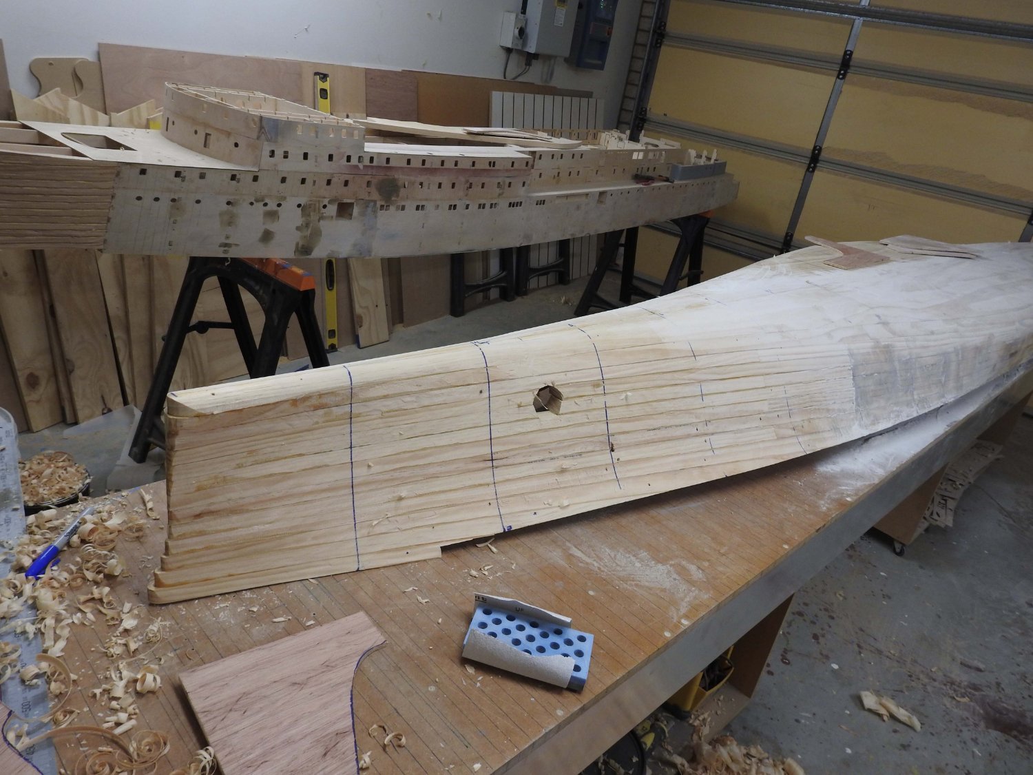
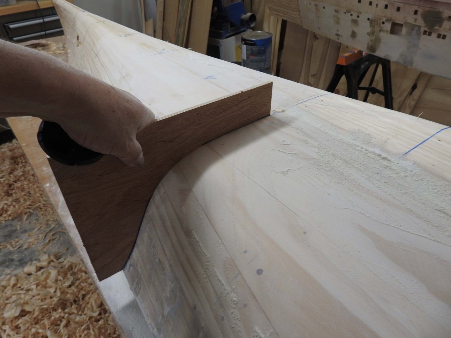
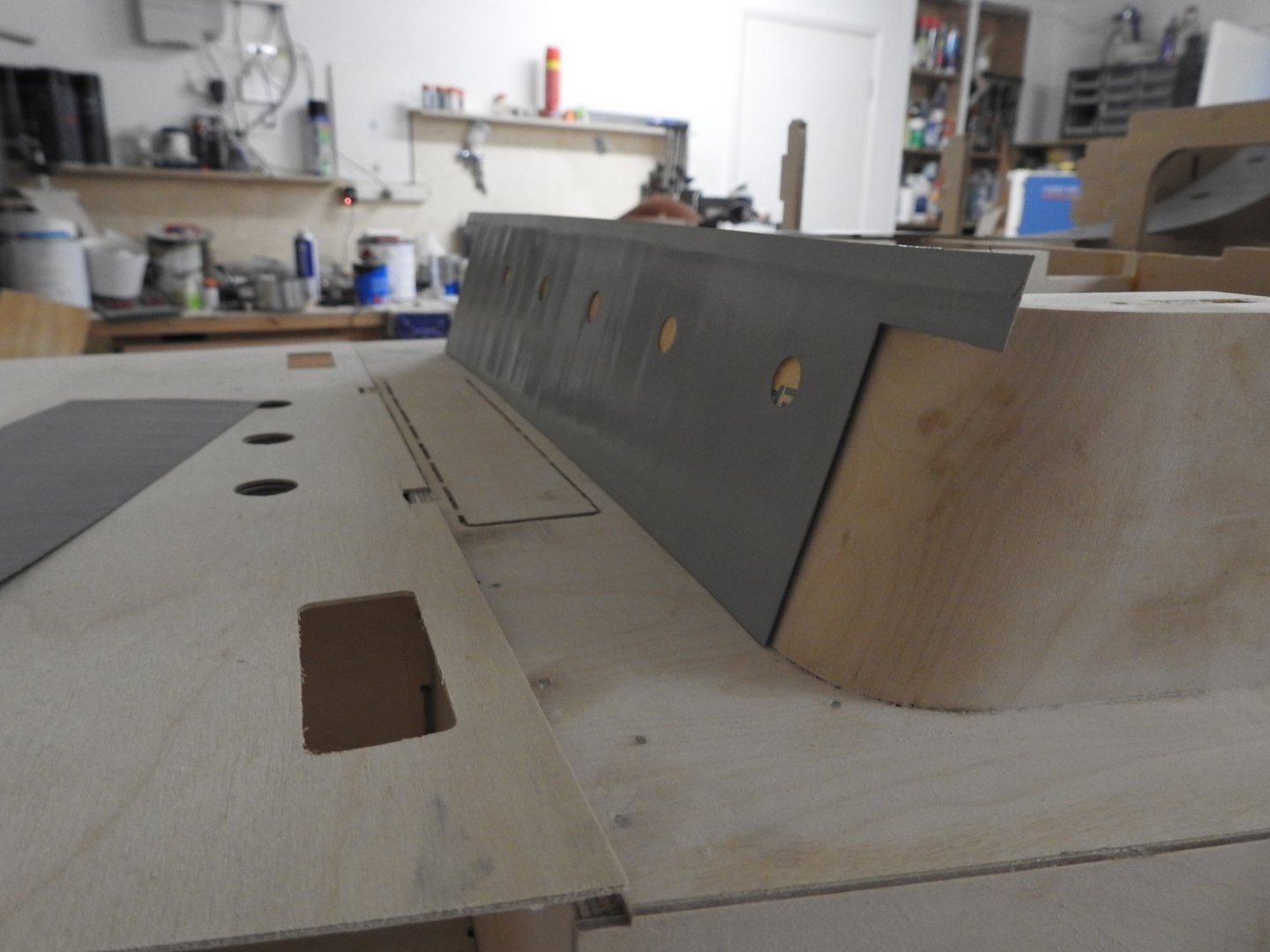
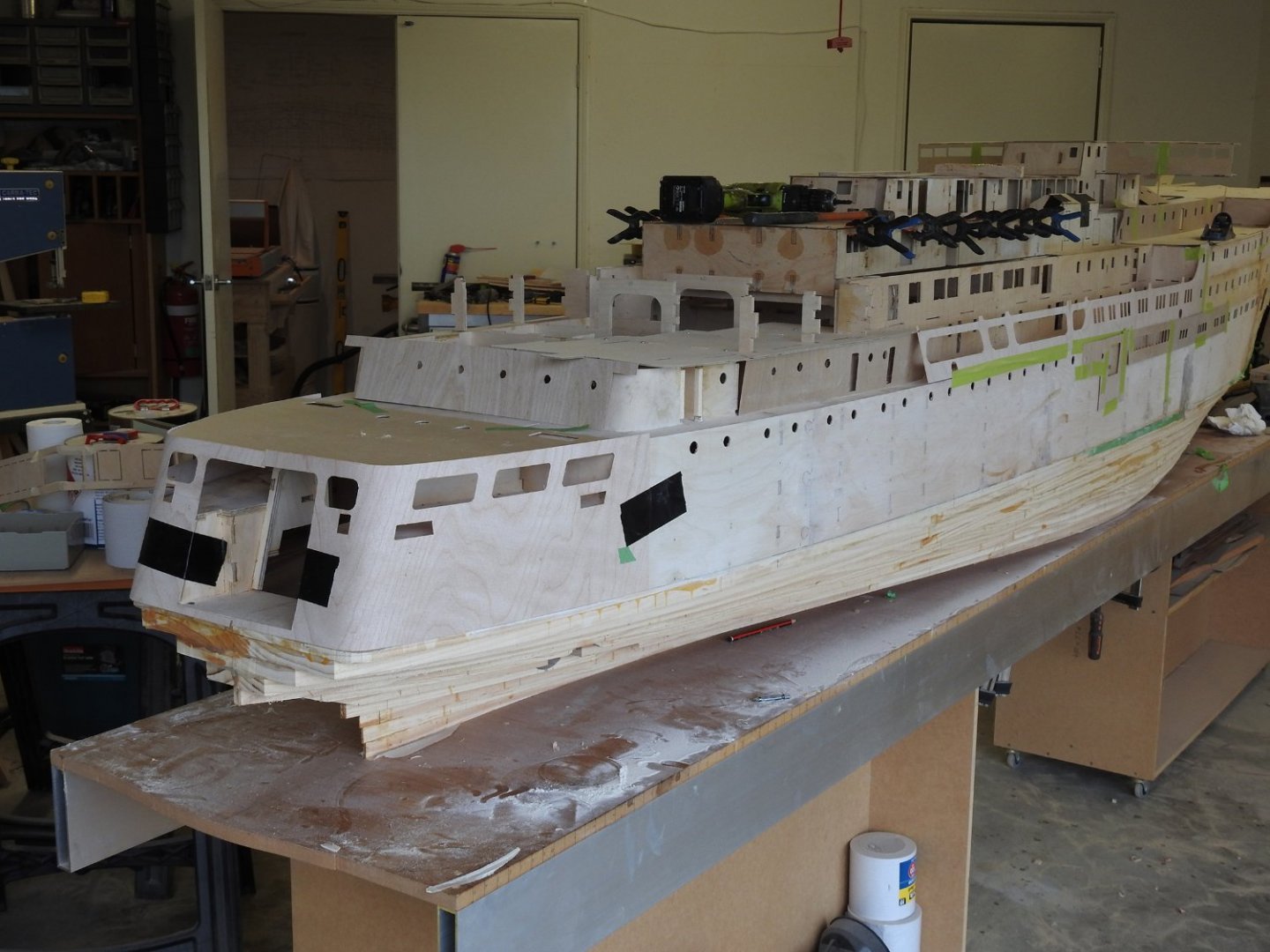
Well I have finally been able to step away from our major landscaping work and start back on model. The thrusters are on their way from UK and I need to get the hull carved so for last 2 days that's what I have been doing. It's been 15 years since I did some serious carving with chisels and planes and boy oh boy are my hands feeling it, all the callouses are gone and I have nothing but blisters to show for it. Carving shown within the final 1mm tolerance ready for aggressive sanding.

- 454 replies
-
- 7
-
-
-
- Union Steamship Company
- Stepcraft 840
- (and 3 more)
-
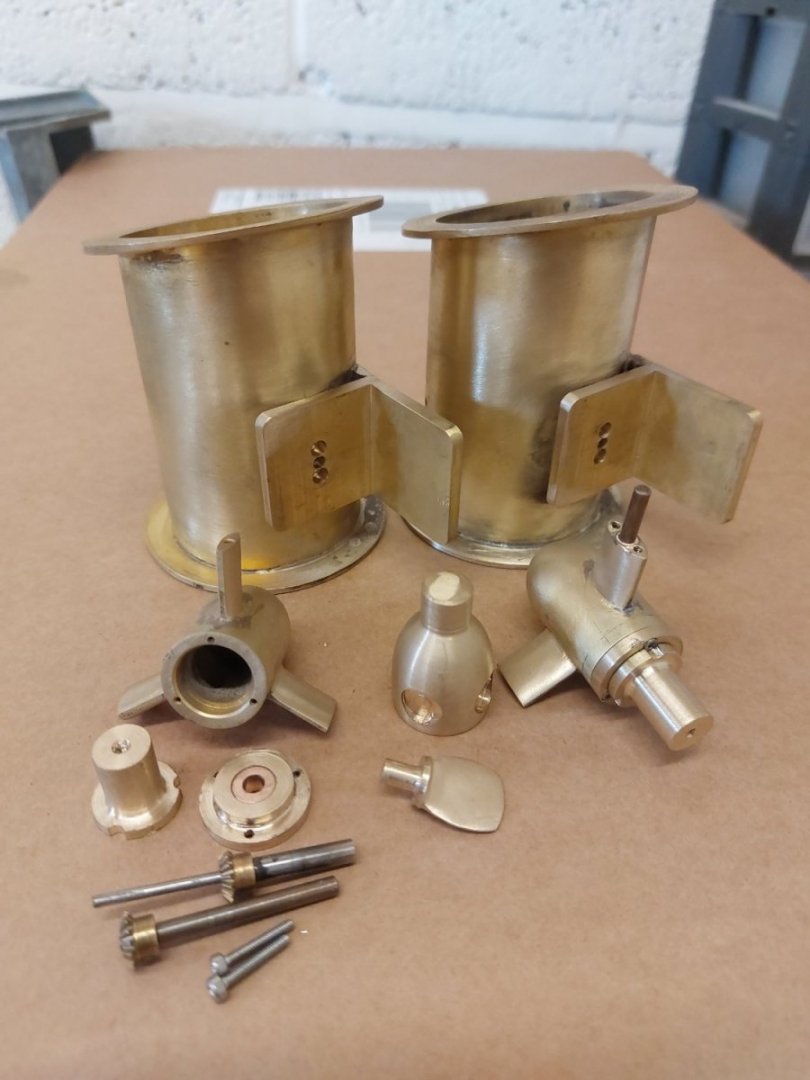
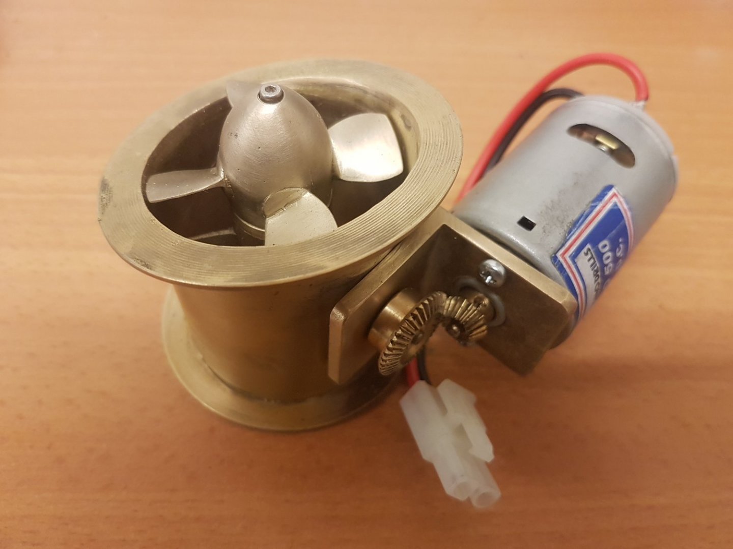
Been busy doing landscaping, and I might add ripped off to the tune of 15 grand in the process...anyway I have some movement in the bow and stern thrusters being made by Simon Higgins of Prop Shop in the UK. Very Verry happy chappy. they are true to scale of the real thing by the way


- 454 replies
-
- 8
-
-
- Union Steamship Company
- Stepcraft 840
- (and 3 more)
-
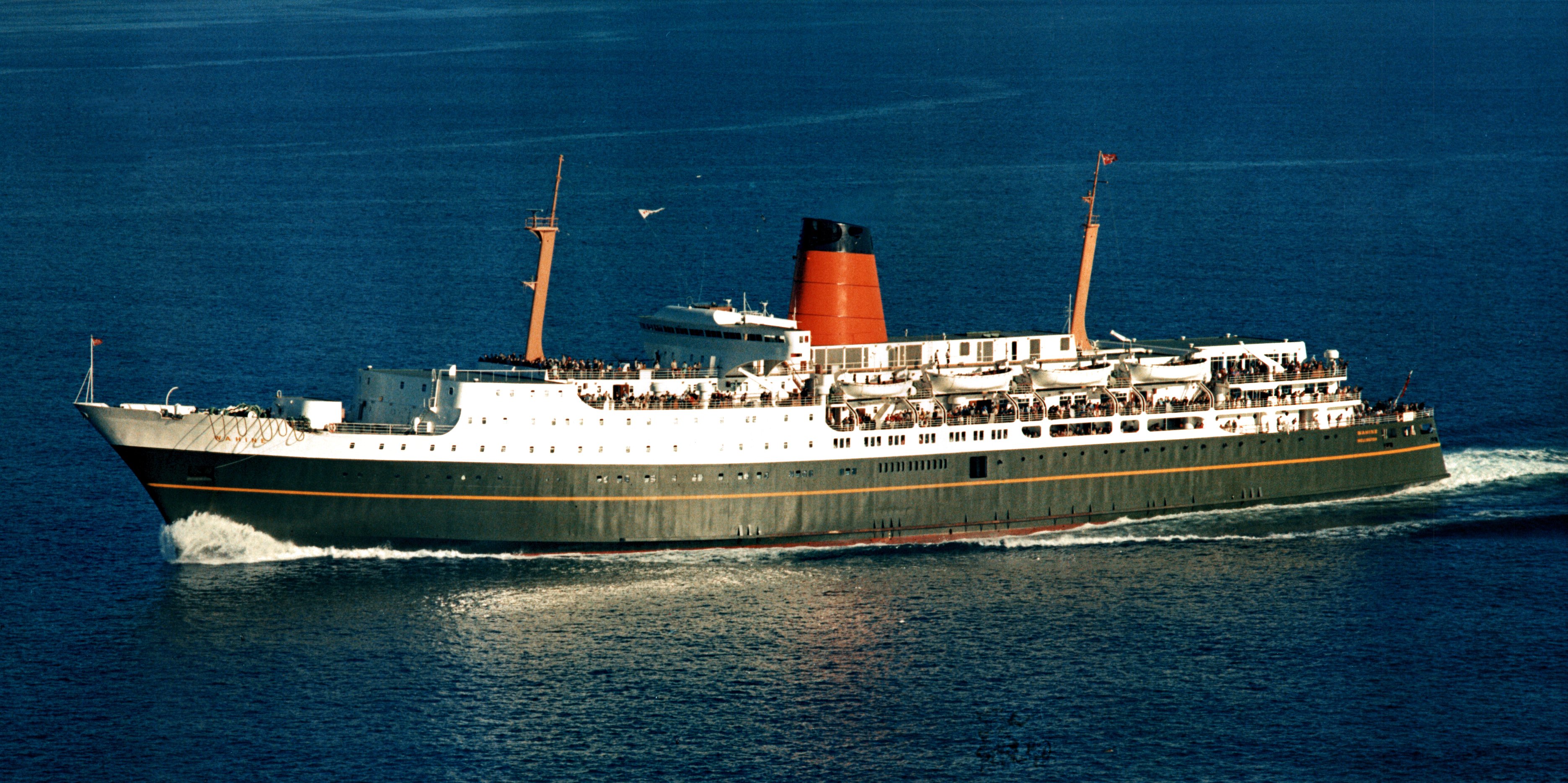
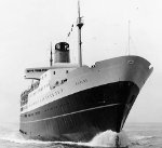
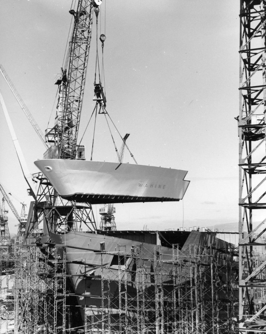
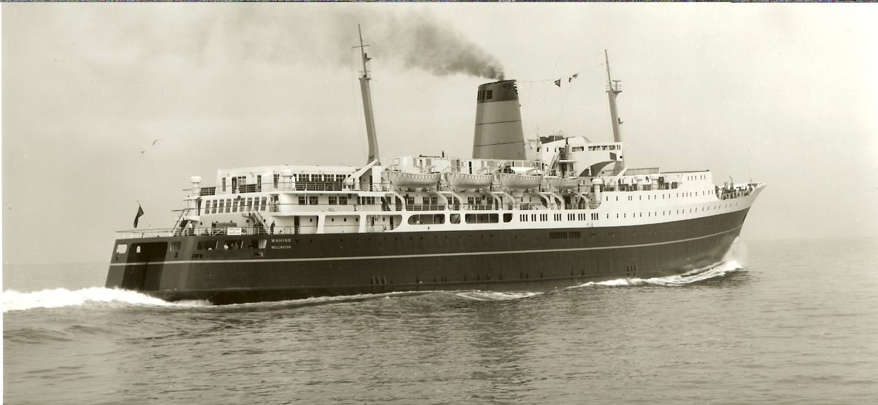
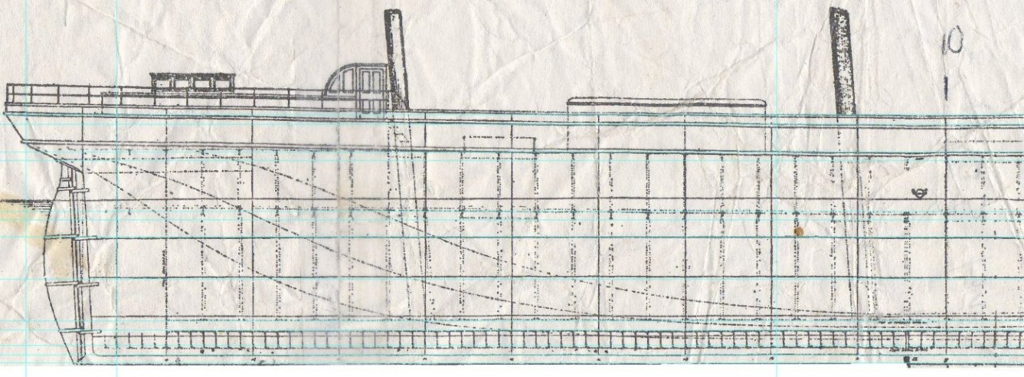
Yeah but keep in mind this is the 60's and tech was not as good as it is now....I guess but lots of old ships have this when framed in this way (transversely), when you look at the way modern ships are framed, which is longitudinally the spaces unsupported are much smaller and form a grid of sharp peaks, a whole different look. But yeah she was bad for it and that's why I hope you can see why the model has to have this detail. I know lots of people are horrified I am but if its one right I think it will look awesome, in some light..that's the key. it needs to be seen in some light and not others and will be hard to see on the white and most pronounced on the dark bronze green hull/ Although its a working model I will be doing the whole hull to not just above the waterline, having the framing plan for every prefab and shell expansion it can be done exactly. Like this but the older ones are quite lumpy due to the bigger unsupported area, as seen here on Wahine's side panels and bow.


- 454 replies
-
- 5
-
-
- Union Steamship Company
- Stepcraft 840
- (and 3 more)
-
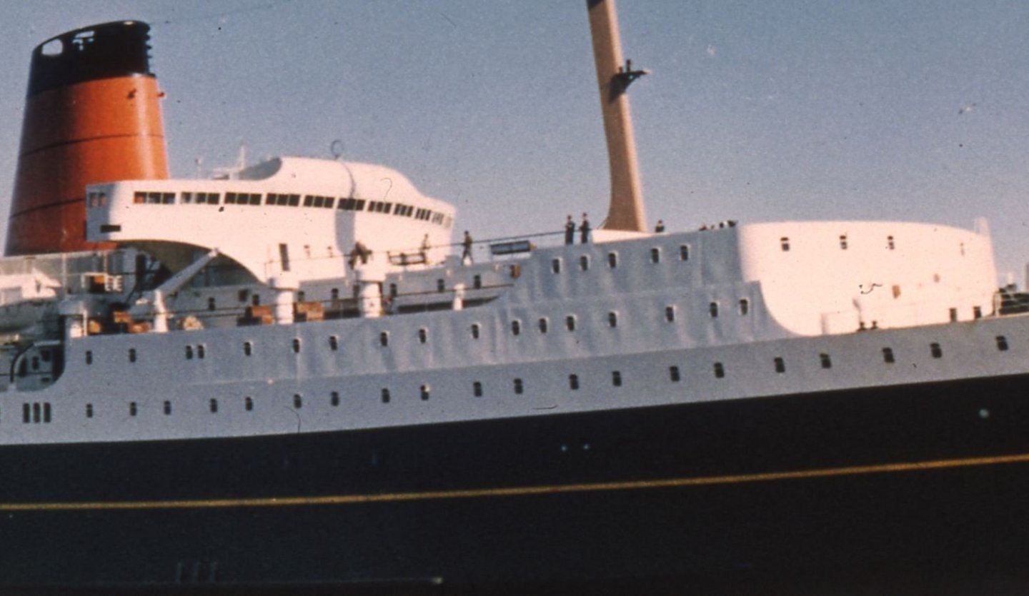
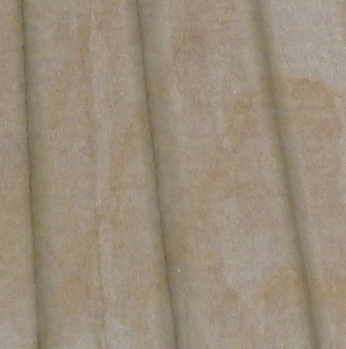
Thanks, yeah you can see the actual effect here and on the first one its very apparent because the sun is directly in front of ship so the light highlights the extent of it, I was not comfortable making it as pronounced as it should be and do not want to risk getting marked down in competition for it making the model ugly.

- 454 replies
-
- 6
-
-
- Union Steamship Company
- Stepcraft 840
- (and 3 more)
-
Ok so I snapped a few shots of one of the plates while the primer was wet so you can see the effect. here you can see some of the acrylic glazing glued in with gorilla glue, film still in place As I said its subtle and understated


- 454 replies
-
- 6
-
-
- Union Steamship Company
- Stepcraft 840
- (and 3 more)
-
OK so this was too heavy handed and I need to halve the depth of the effect.
- 454 replies
-
- 3
-
-
- Union Steamship Company
- Stepcraft 840
- (and 3 more)
-
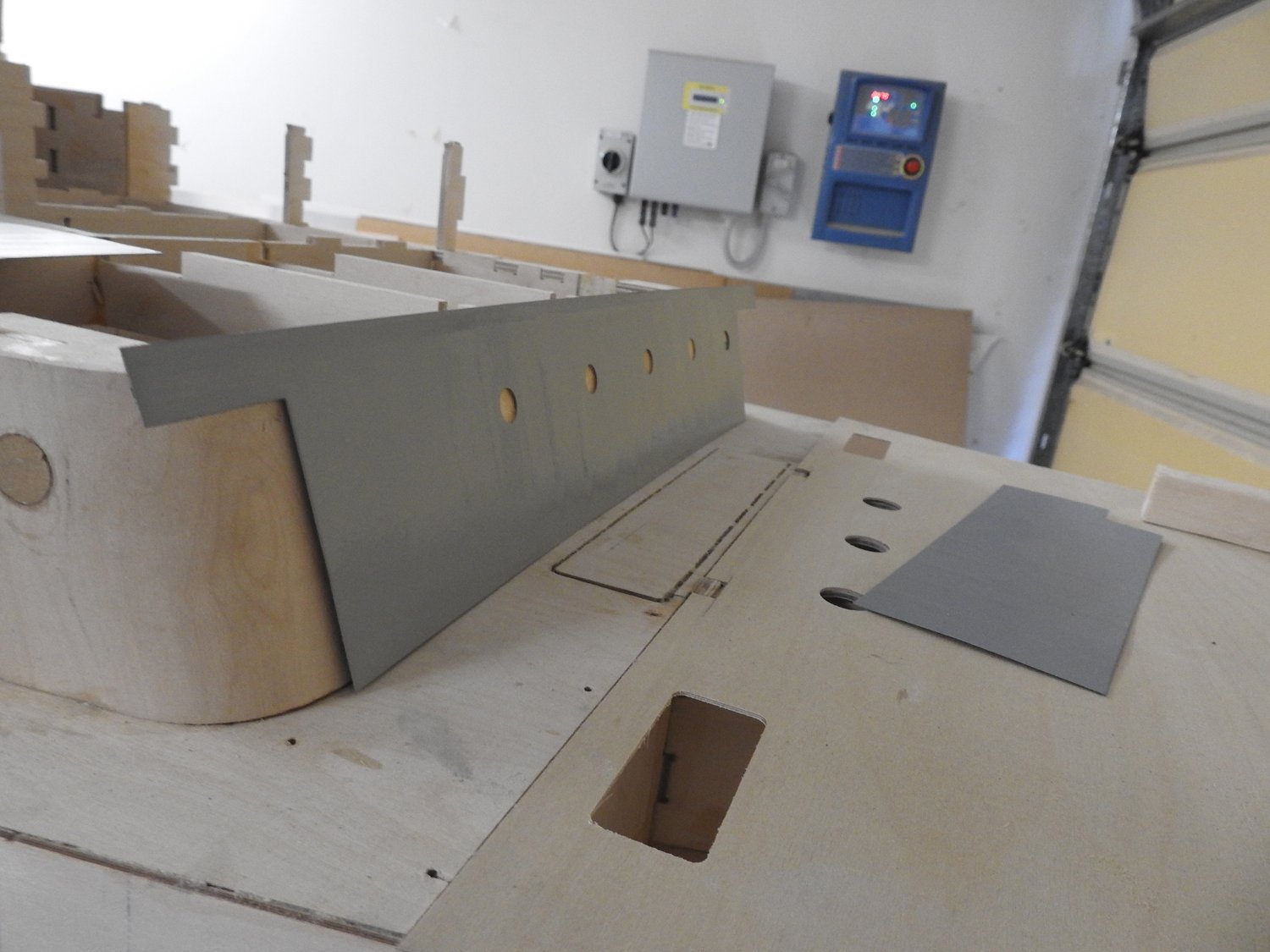
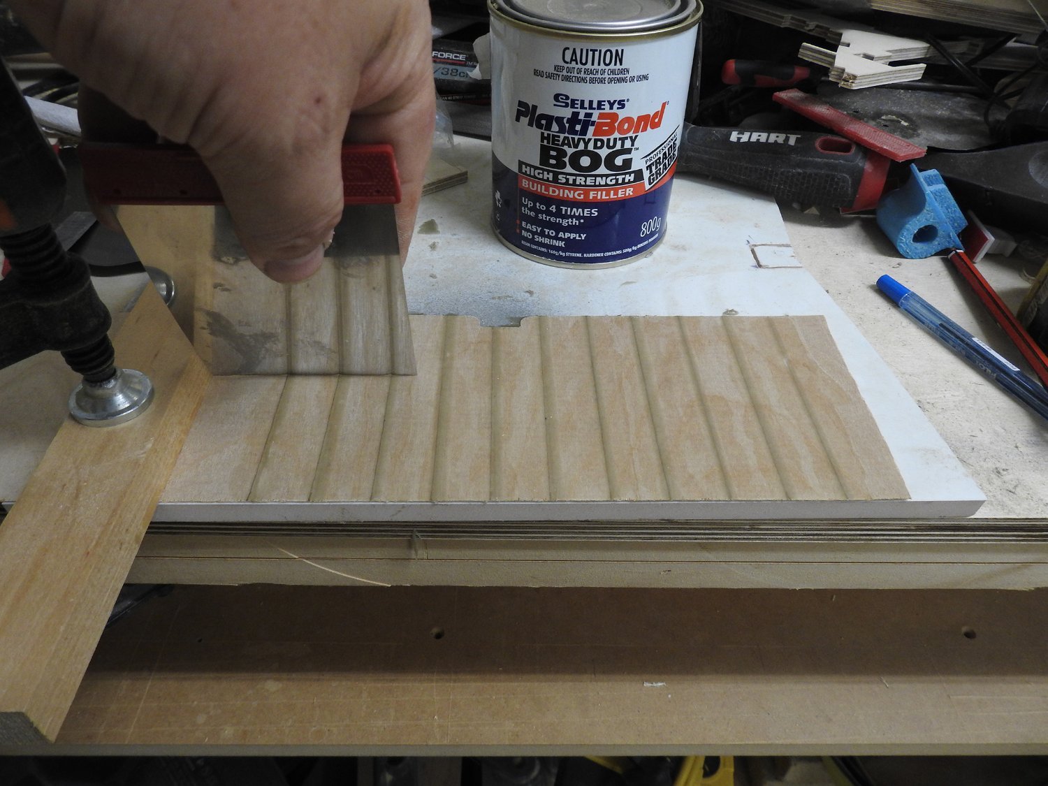
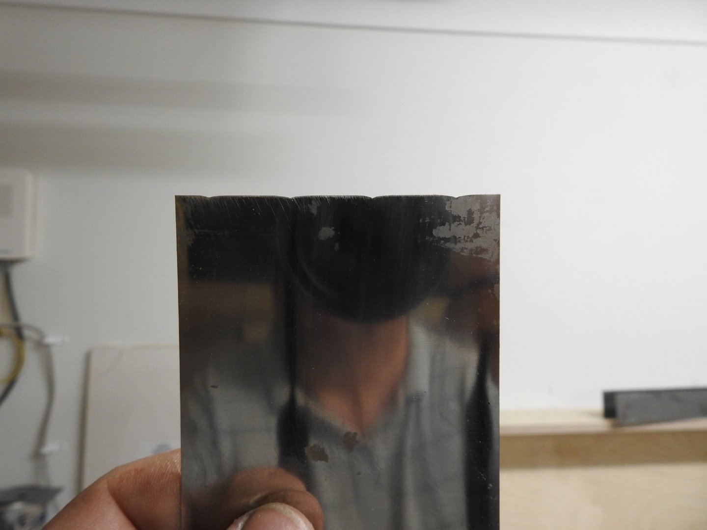
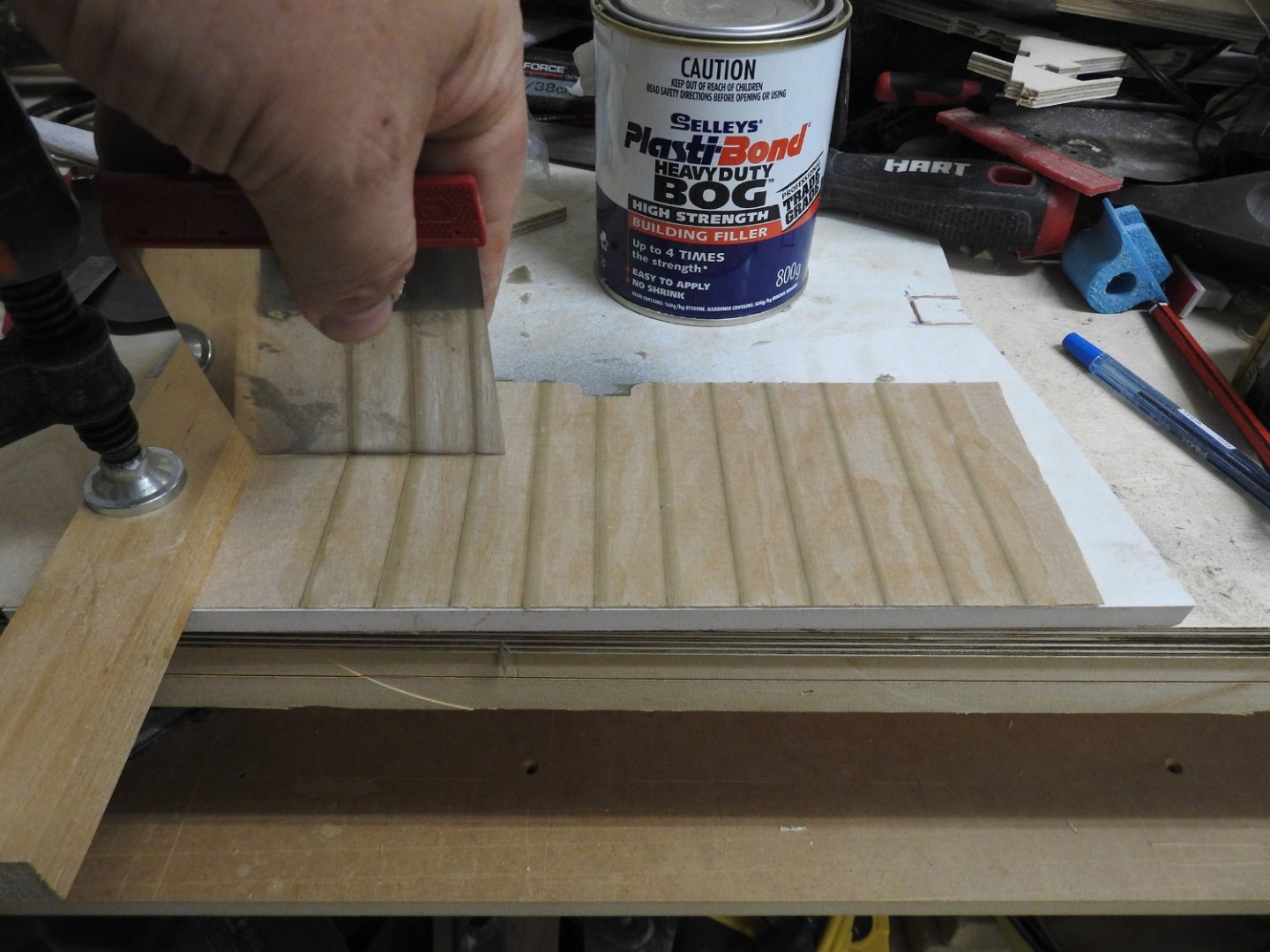
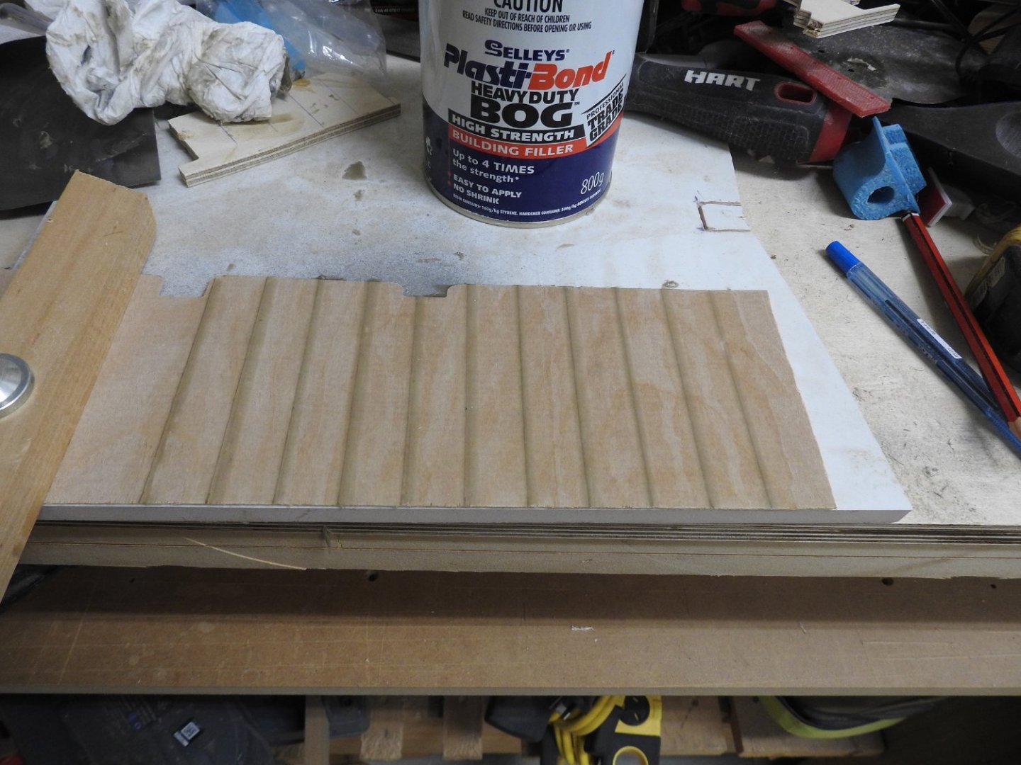
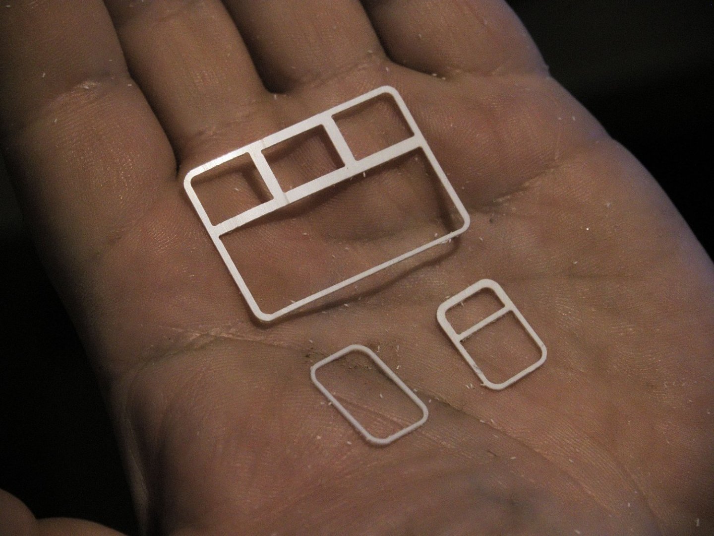
Well I think I have found the key to tin canning plating. The results are very very good. I have done tests with a number of fillers and I came to use selleys plastibond.....as usual, incidentally my father used this on his museum models to surface the bread and butter hulls he did for his models in 1967 and they have not cracked one bit to this day as they are still on display in the Otago Museum. So make a scraper like this from thin steel, in this case high carbon flexible steel, I used diamond stone to file the shapes. as you can see here 4 frames are in this scraper with the depth of the effect only .5-.6mm deep which is almost too much!! I need to allow for sanding which will knock it down a bit and also the high build primer which will fill the hollows a bit, all that will lesson the effect, I want it to be subtle, and only visible in certain light. Then apply...very quickly the filler to the pencil lines and drag the scraper along a clamped straight edge. Note also the grain in the finnish ply is so fine it does not need filling. another reason it's worth the extra money. Make sure you have a flat surface underneath like a tile and be very careful to mix the filler clean, any crap in it will cause drag marks. the result is this. because the plasti-bond is greenish you can see the effect works and the taper off in shape here. Once dry sand and randomise how heavily from frame to frame and round some ridge lines more than other and the result is what you see here..................,when the paint is dry I will show you. Time taken per plate 5 mins
- 454 replies
-
- 7
-
-
- Union Steamship Company
- Stepcraft 840
- (and 3 more)
-
Haha, Keith I work full time still and work on this from 2.30- 630 every day and weekends, but the CNC makes quick work of the build as everything is pre-cut and fits. Also being a furniture maker and guitar builder means I have the experience to work quickly and have the gear to. It does not feel quick to me trust me, and don't forget to that you guys have not seen the 4 months sitting on the computer modelling all this, that was the real build.
- 454 replies
-
- 5
-
-
- Union Steamship Company
- Stepcraft 840
- (and 3 more)
-
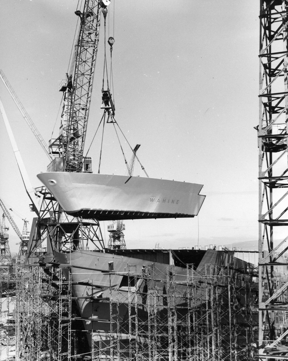
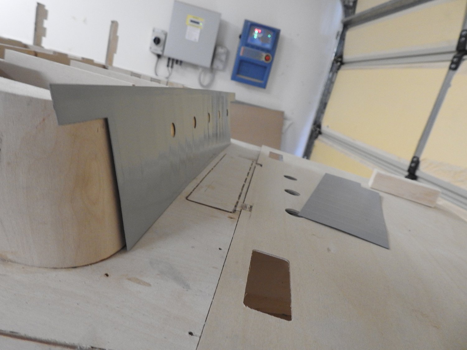
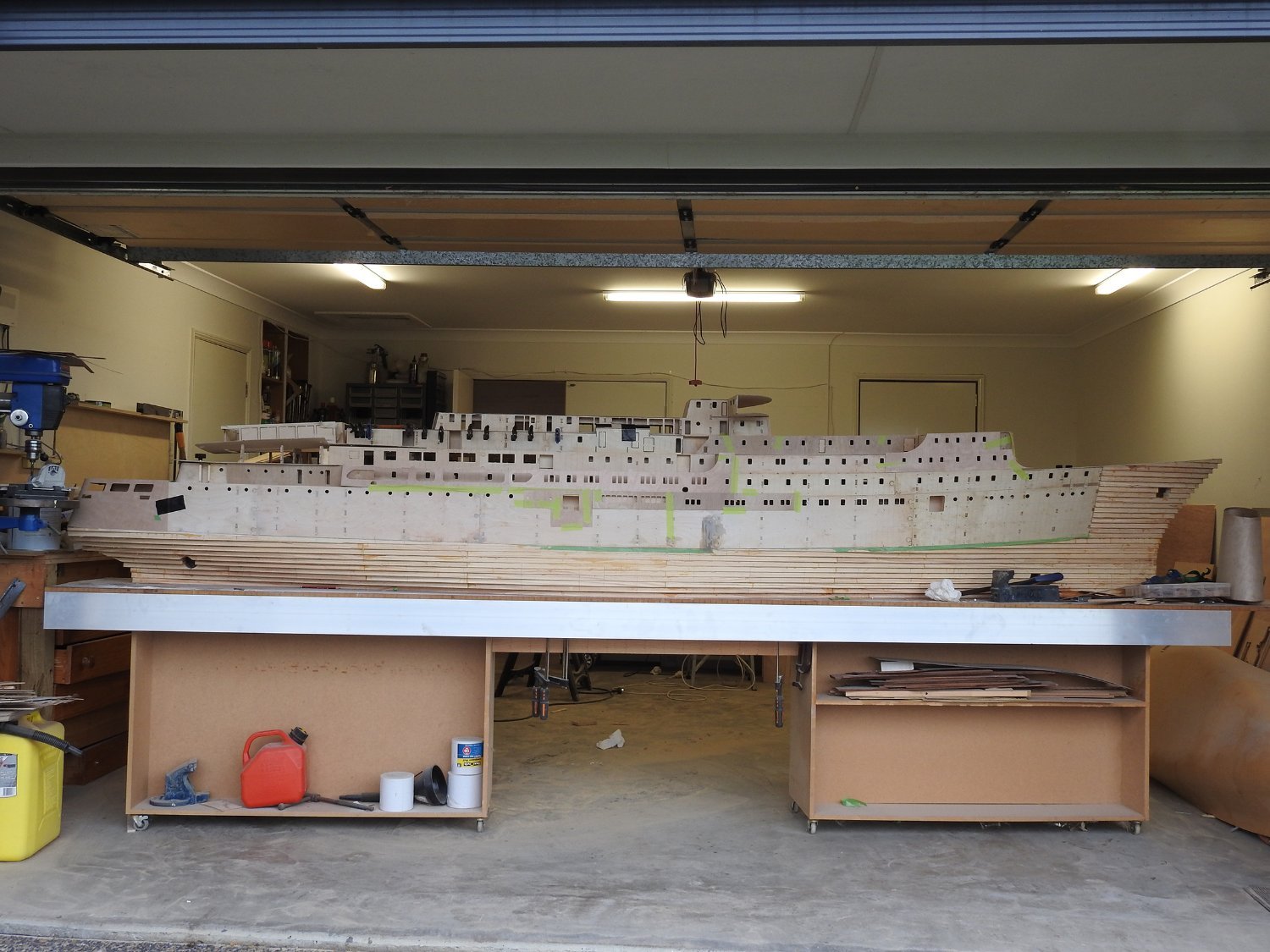
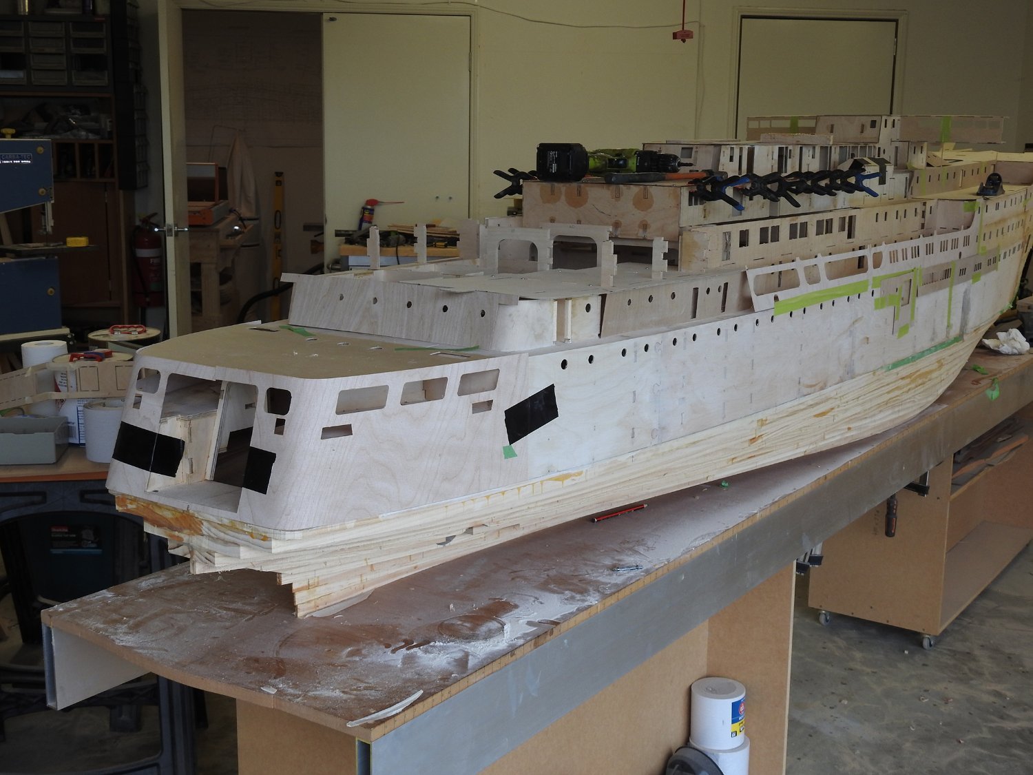
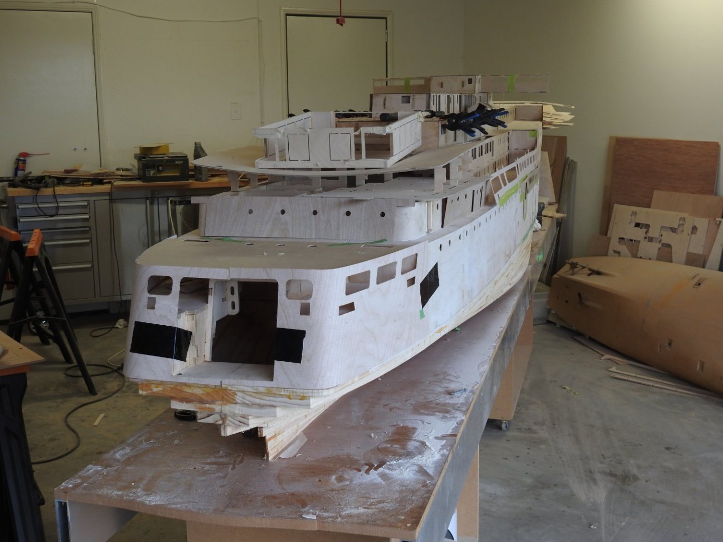
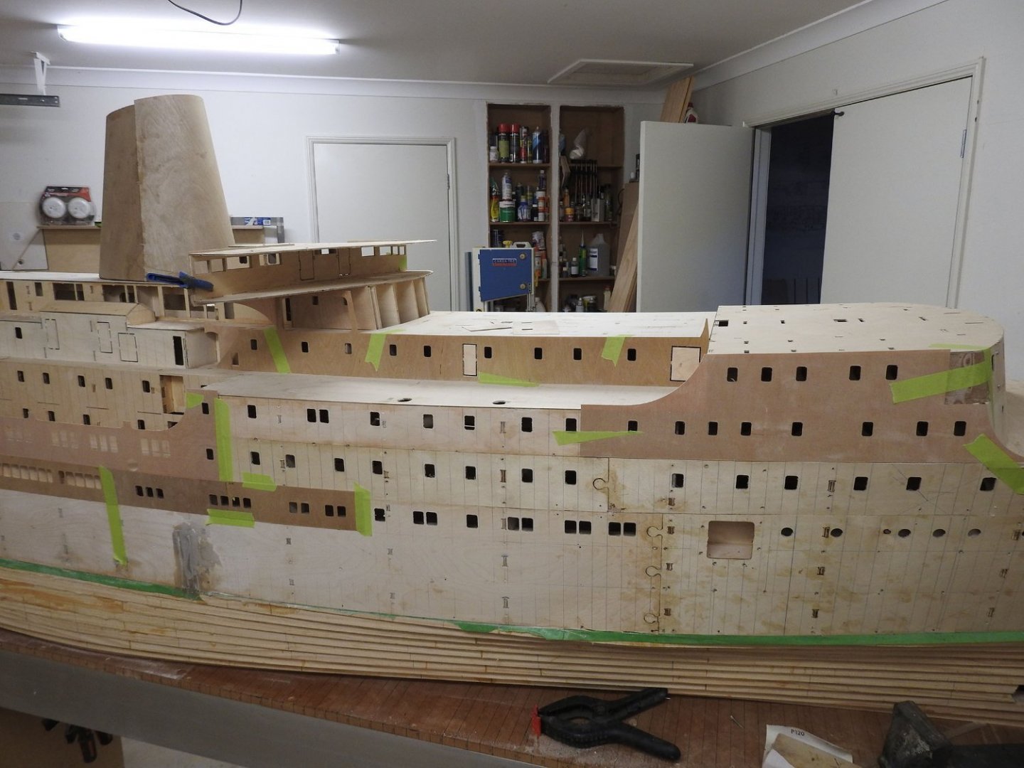
Some progress shots I started to fit the shell around the stern and mooring deck which when on properly starts to look like a ship! I have to admit the stern is one of my favourite parts. the framing and bulwark stays in the mooring deck will all be built from 1mm ply and will stiffen the .5mm ply no end. A shot side on from a bit back to get the size, this is a double garage by the way. Once the plating around the lower level of aft superstructure is primed and on I can build the cafeterias, currently that is where the top lounge is drooping down on top of it, once this is done it will start looking better, mast bases will be on next week to. Of course hull carving will make a difference but waiting on a certain person before I can do that and for my thrusters. This shows the actual finished .5mm surfaces of the forward Superstructure and Deck, you can see the 12 inch waterway along the deck edge next to the mushroom vent holes. The joint of the superstructure and deck has a 6mm strip of .5mm ply glued to the bottom, the deck bar as its called but its not on yet of course. You might be able to see how the windows will be done here, the 2mm clear acrylic is glued flush into the 2mm substrate before plates are glued on, the .5mm plates are treated for the tin canning effect primed and glued on over the glazing and then the styrene windows are pre painted and glued into the hole in the .5mm plates and masked with liquid masking ready for painting the hull. Anyone got any opinion of gorilla glue?

- 454 replies
-
- 11
-
-
-
- Union Steamship Company
- Stepcraft 840
- (and 3 more)
-
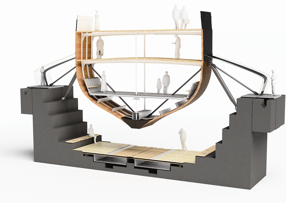
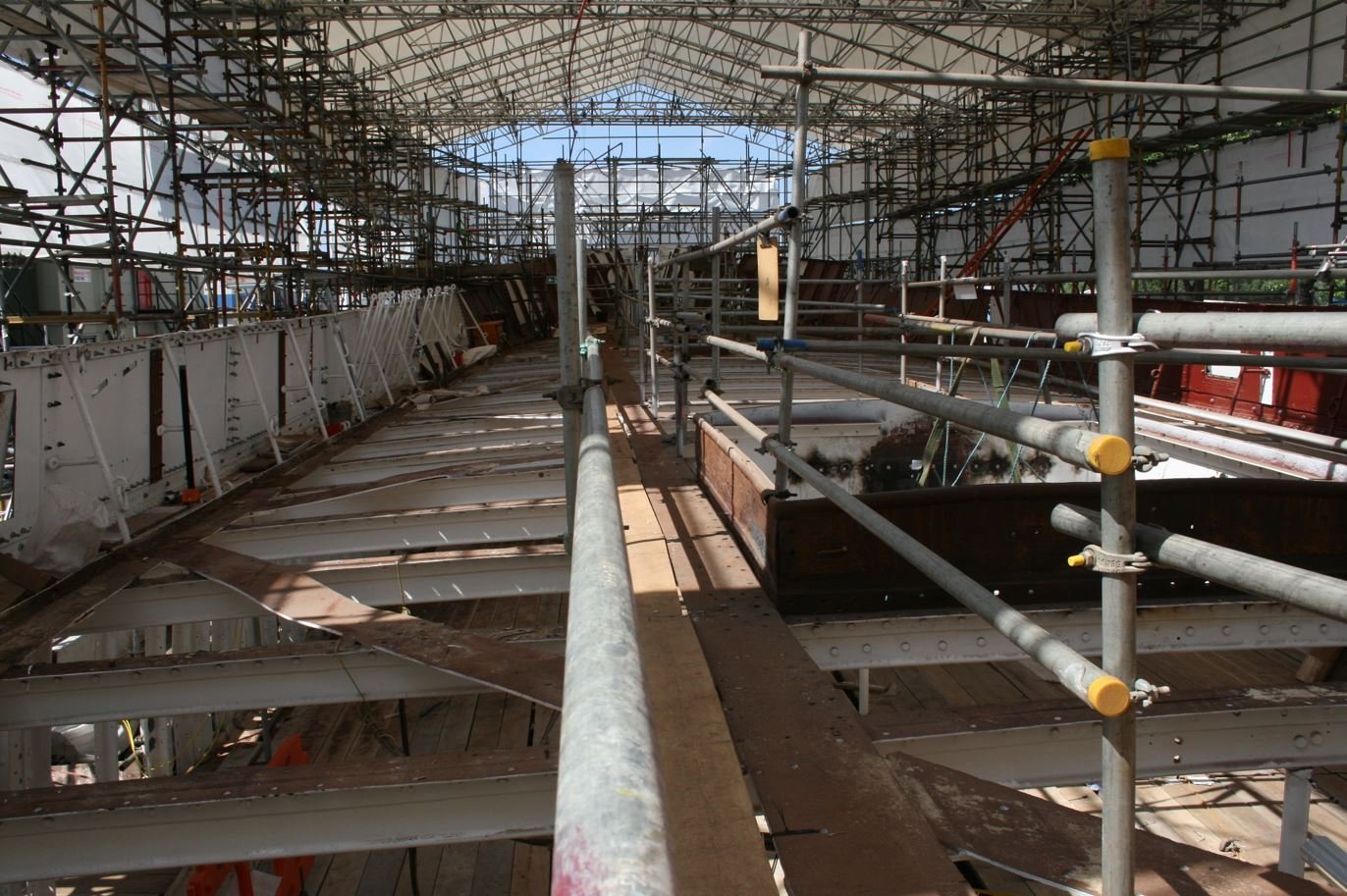
The structure that supports the Cutty Sark is a cantilever system, I will try to explain it as it was explained to me. Along both sides of the hull are cantilevers that are each made of 2 primary girders,one attaches to the ship at waterline and mounts higher up to ground, the other attaches at same point and attaches to ground at the base lower down forming a triangular crane like frame, when 2 of these are placed either side and downward pressure applied to them the lock up and tighten the grip on the area between the frames, this is counteracted by quite heavy beams running through the ship that effectively the ship hangs from, there are also considerable doubler frames that have been added to the rusting original frames but they carry very little weight other than the local stress of the ships fabric itself like the planking and adjacent structure. Personally I hate what they did, I think the lines are lost and the canopy looks nothing like a sea or wave, since when does ocean look like the ship is sitting in a soft sponge. The way it's been positioned shows less than the normal free-board as well anyway which gives a bad impression of the hull. Just my opinion but hate it. Of course this is a simplistic explanation and this image shows it better.
- 444 replies
-
- 4
-
-
- Cutty Sark
- Revell
- (and 2 more)
-
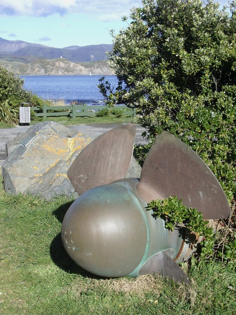
Yep it has layers. Museums seem to be forgetting nautical history across the board. even now I am getting a museum in new Zealand to find the Wahine builders model I saw and photographed in 1986. How does a museum lose a 3m builders model of a ship that has such a part of history in NZ. even the anniversary's of her sinking are in the news every year.
- 444 replies
-
- 3
-
-
- Cutty Sark
- Revell
- (and 2 more)
-
You do have the Jordan ones, they are the wrinkled ones and the dark ones are the Lloyds ones but also jordan.
- 444 replies
-
- 1
-
-
- Cutty Sark
- Revell
- (and 2 more)
-
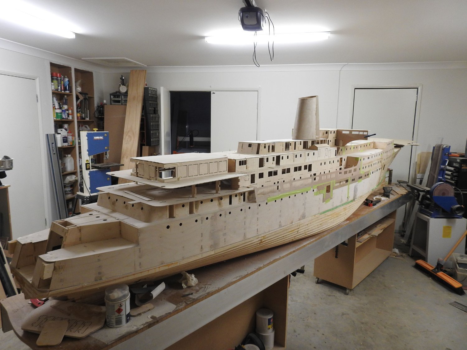
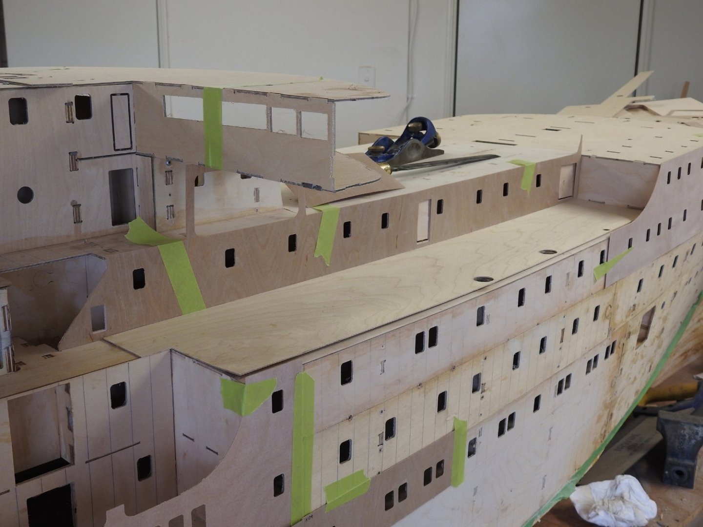
Some update, fitting finish plates to model, they will be primed and have windows fitted along with any structure like stiffeners and rivets before being glued to model. The curtain plates can be seen protruding up in places. Also the base for the Aft lounge sitting on the upper deck can be seen and the large 56mm windows, as you can see, it needs an interior. Added this a a similar shot for comparison. Above showing the promenade screen sitting in place shows the large area that has to be finished before being able to close it in. The bridge is going to be a very difficult piece of work, the hard parts are not shown here yet.

- 454 replies
-
- 7
-
-
-
- Union Steamship Company
- Stepcraft 840
- (and 3 more)
-
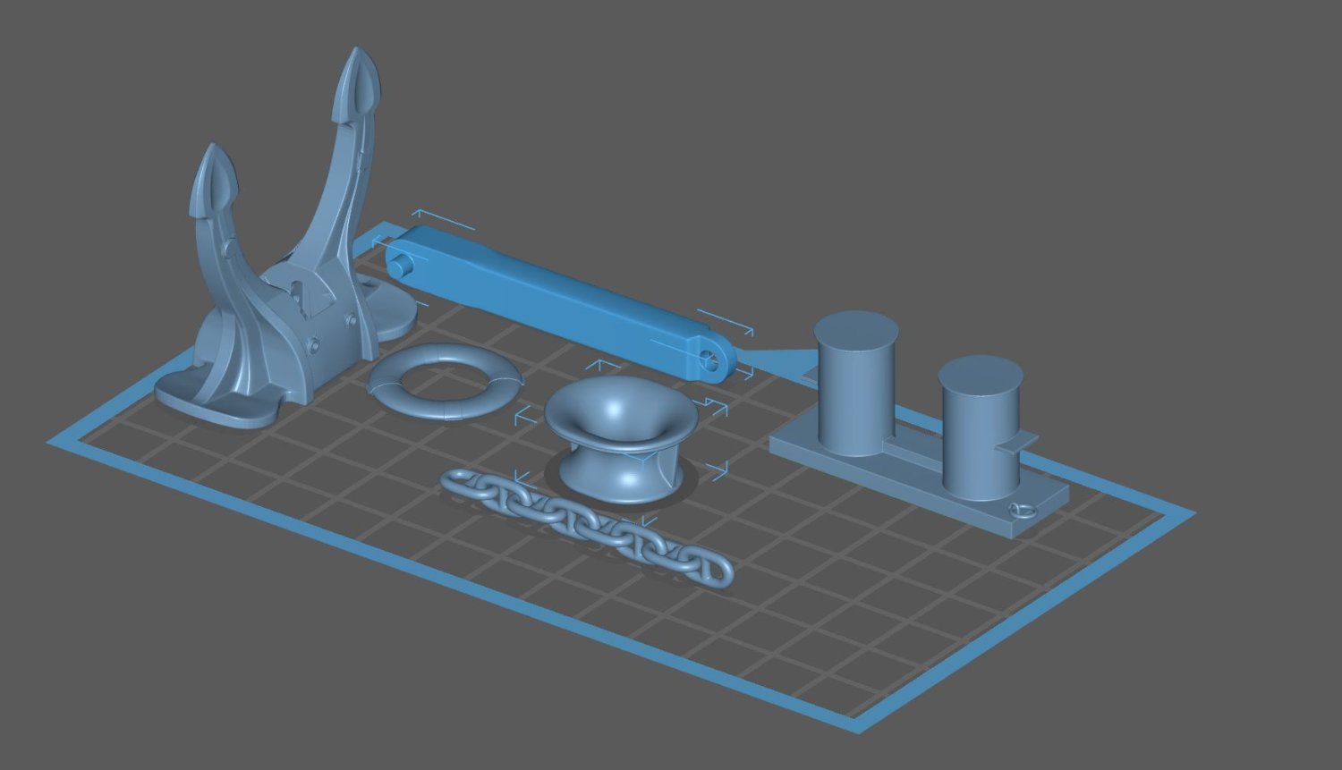
Yeah I have done printing before just not an expert yet. These are not setup for printing in this image but these parts are done. I have just put these on plate for display only

- 454 replies
-
- 6
-
-
- Union Steamship Company
- Stepcraft 840
- (and 3 more)
-
Cool I might see what I get, I only need the rivet heads not the shaft and need about 3000 of them so this will be good. Its the supports that take practice I am finding, actually I wonder.....hmmm I might even be able to print lengths of weld seam with a tiny bit of wobble. That scales at between .6 and .9 in width off that photo. Dam it why do the holidays have to end today.

- 454 replies
-
- 4
-
-
- Union Steamship Company
- Stepcraft 840
- (and 3 more)
-
A bit of history about the campbell plans, assuming these are the official ones from the Cutty Sark shop. They were drawn in the 50's for the restoration, now in saying that during that restoration they did not survey or measure the hull so in regard to the "big" details like lines, sheer, stem rake etc it is out, but in regards to fittings and things like that it is pretty good but I have noticed some errors in things locations in the past. have you got Photoshop? or can you open PSD files? if you do I will superimpose Campbells over the file I used in the workshop and shoot it to you so you can make your own conclusions
- 444 replies
-
- 3
-
-
- Cutty Sark
- Revell
- (and 2 more)
-
Well I have been experimenting with making windows, I have cut all the 2mm Acrylic glass on the ship now so that's done. So I was playing with styrene or PE for windows and have opted for styrene as I have found I can in fact cut it on the CNC without it melting. This is a HUGE advantage as gluing the frame to the glass can be done neatly with Tamiya cement and all the edge bars around the frames can be welded on, all I will do is make a jig that holds the frame in the bottom of a hole and bend in the lip to fit the sides and weld, then paint and add the wood mullion and glue to the clear Acrylic, this is going to produce pretty faithfull windows to the real thing, and not too slow either which is just as well as I have 300 odd windows to make of varying types
- 454 replies
-
- 8
-
-
- Union Steamship Company
- Stepcraft 840
- (and 3 more)
-
The Scale decks planking on the new one is pretty close I must say, at 1/96 each plank is 1.3mm so hard to do. Also no one really knows what the truth about the deck was when she was a working ship. The decks after the 50's restoration were a sham deck and laid on ply (due to cost and ease of obtaining wood).. The decks as restored are based on old photos and what not but still... the way it is done now you have the margin planks around edge as well as 2 king planks that run alongside the deckhouses, and the sides and middle planking are separated by these king planks but there is little to say it was done like this when she was built. Nepean Longridges book was written while she was still afloat as a training ship and in his observations makes no comment on these king planks other then they go around deckhouses and hatches. I would suspect the 2 king planks are in the way they are is to make access to the longitudinal deck stringers which correspond to them easy to access.
- 444 replies
-
- 3
-
-
- Cutty Sark
- Revell
- (and 2 more)
-
Here you can see the main hatch is 2 spaces to get the location for the beams the frames shown here are the webs and are the locations of beams. If you take the distance from the break of the poop to the after side of main hatch and divide that into 15 sections, that's your frame spacing. assuming model is accurate anyway. I wont bug you if your not too worried... I cant help myself when I see Cutty Sark given my time working on her. Just PM me if you need any info..
- 444 replies
-
- 6
-
-
- Cutty Sark
- Revell
- (and 2 more)