HOLIDAY DONATION DRIVE - SUPPORT MSW - DO YOUR PART TO KEEP THIS GREAT FORUM GOING! (Only 72 donations so far out of 49,000 members - Can we at least get 100? C'mon guys!)
×

Richard Dunn
-
Posts
529 -
Joined
-
Last visited
Content Type
Profiles
Forums
Gallery
Events
Everything posted by Richard Dunn
-
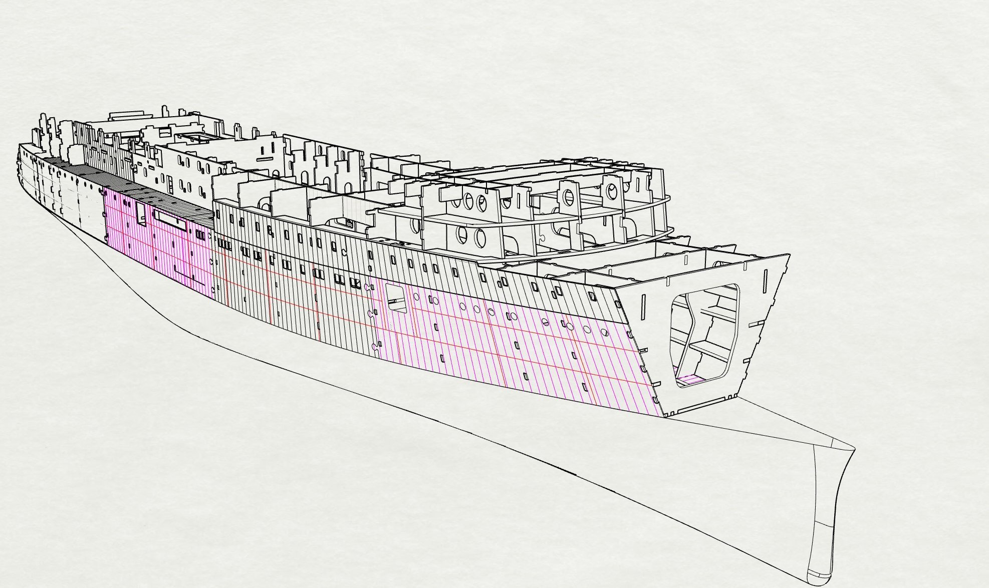
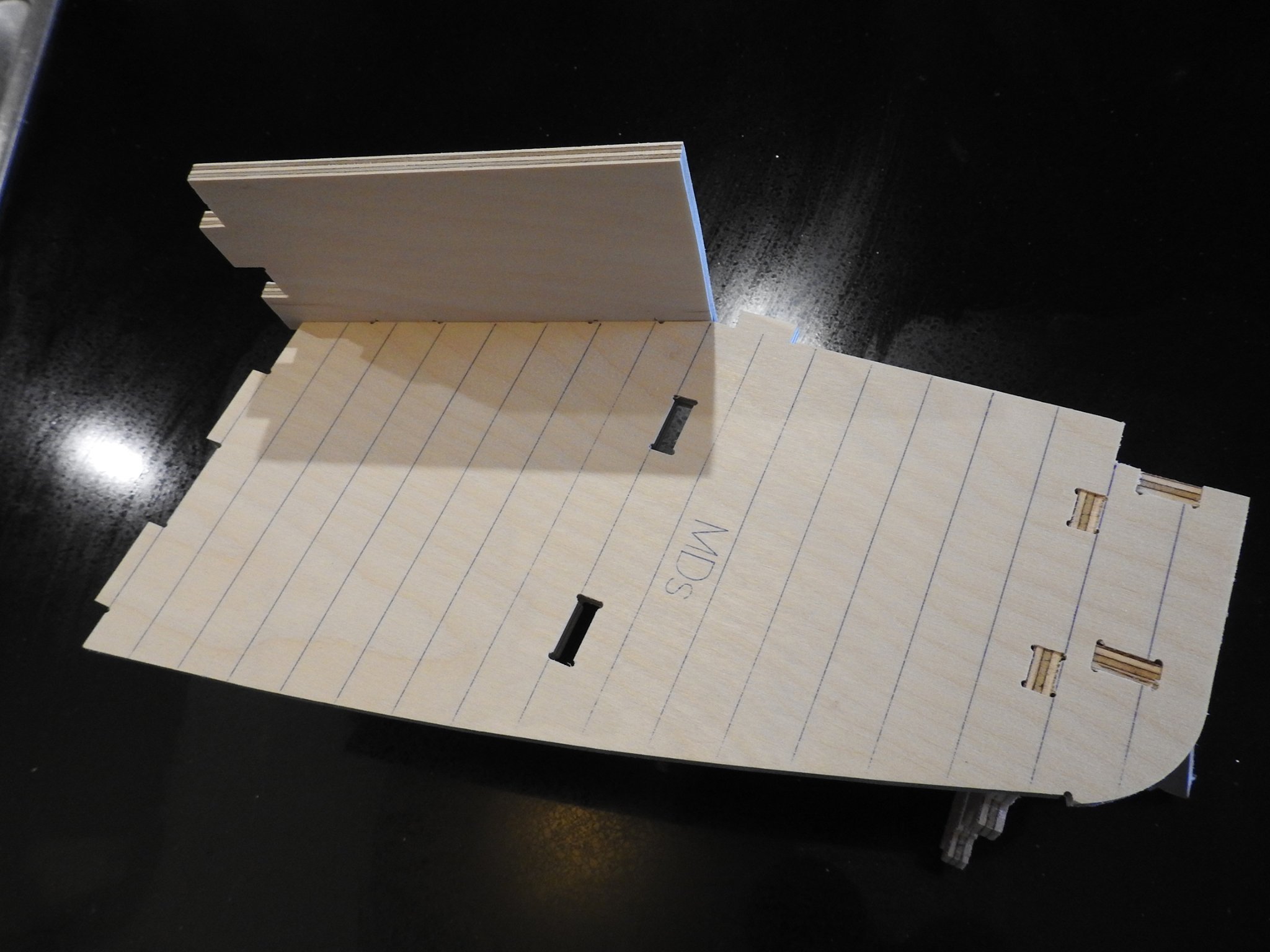
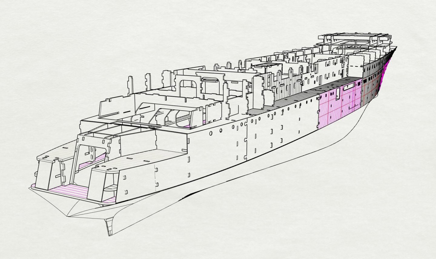
 Step 20 forward superstructure panels
- 454 replies
-
- 1
-

-
- Union Steamship Company
- Stepcraft 840
- (and 3 more)
-
Step_19 forward 2mm deck panels, leave uppermost one un-glued for Bow Thruster installation

- 454 replies
-
- 1
-
-
- Union Steamship Company
- Stepcraft 840
- (and 3 more)
-
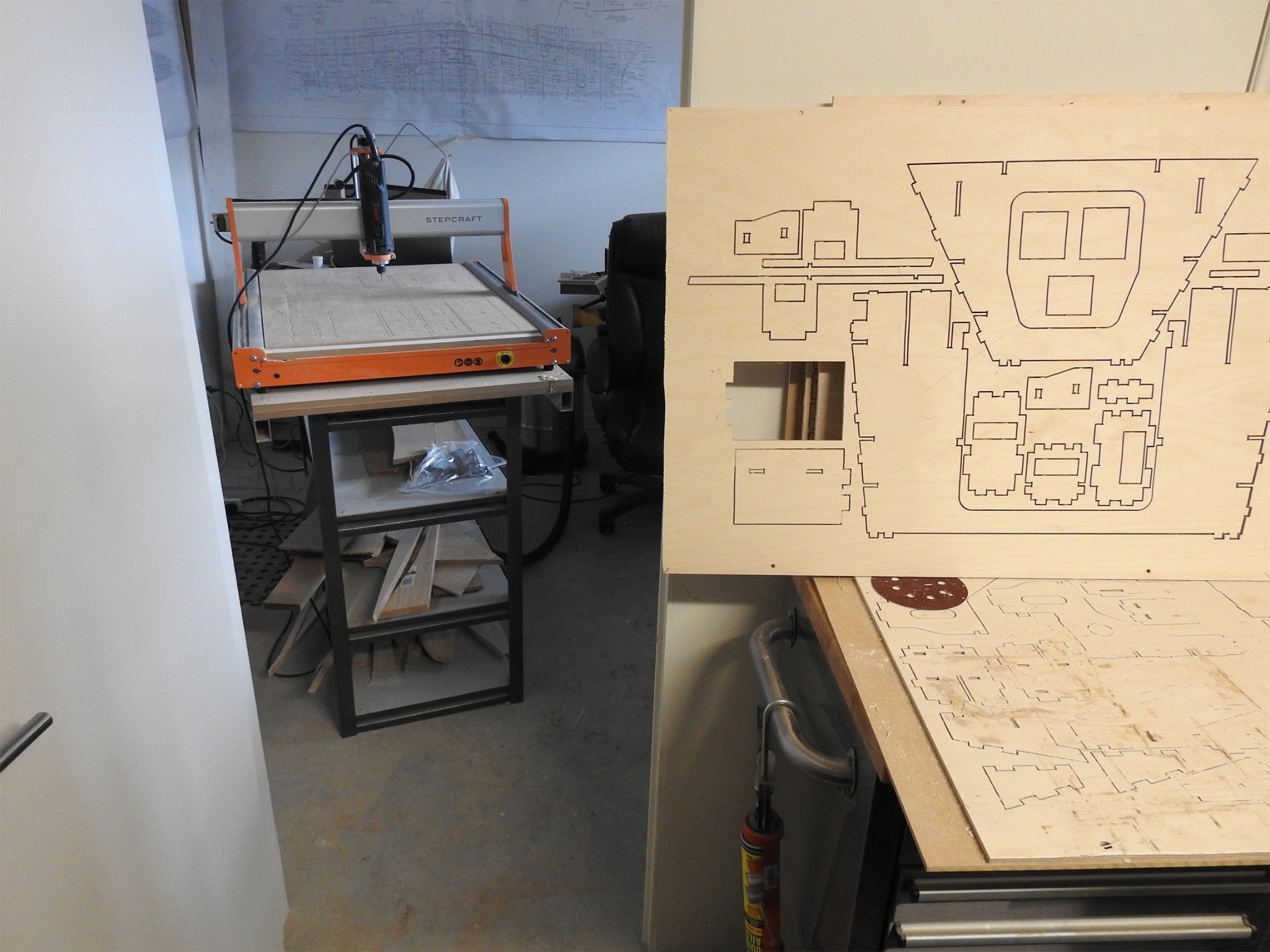
I am not sure if anyone has wondered this or not but thought I should explain that the parts which have twist like stringers and hull panels are obviously needing to be accurately developed to a 2d shape, especially as they have tenon holes to align with so Rhino has tools to do this for hull plates in steel, aluminium etc so its nota problem, it asks for the surface to develop and then you select any curves on that surface and it lays out the shape as well as the curves on the surface for you which can then be placed on sheet template for cutting. Another shortcut I have done is to eradicate bevels, I have allowed for the parts to sit on the 1 corner and allow the epoxy glue to fill the space in the bevel. this is to make process faster but also it makes the accuracy a lot better as in the process of bevelling you could potentially create fit errors, the glue I use prefers to have small gaps so strength is not an issue. I wiil do more pages tonight after work but I have cut all the parts above already and are sitting on my bench taunting me, I intend to assemble this over Xmas break and even carve hull then to, a week each I would think.
- 454 replies
-
- 3
-
-
- Union Steamship Company
- Stepcraft 840
- (and 3 more)
-
Thanks guys The best part is the actual assembly should not take that long..days not months, what I really have to figure out and I would appreciate some advice on this is the painting , as in what and when, once I start adding the plates to this set of pages you will see what I mean but not tackled anything this size for that. I think the .4mm plating should be pre primed prior to gluing onto substrate 2mm? any gaps and joins that need touch up can be done at end. I should point out to that as this is being built its still only temporarily fixed to lower hull, once the upper is assembled I want to remove it and then carve the lower hull, I think it makes sense to do this because at the moment the hull is firmly fixed to the base board which is level and straight, with no rise of floor, so measuring heights for knuckle line can be done from the baseboard with no worrying about the hull leaning. Also I should point out that this should be very stable, the ship is a top heavyish design but with B&B lower hull and very light topsides and even lighter top lid it should be fairly stable in even an unballasted state as the weight is all low down. I do want to make kitsets, that was the plan , comprising of this CNC lark, photoetch and resin printed fittings. Actually if anybody has suggestions for subject matter go ahead, Cutty Sark is not an option clearly. I realise that this size is not suitable though...😃
- 454 replies
-
- 1
-
-
- Union Steamship Company
- Stepcraft 840
- (and 3 more)
-
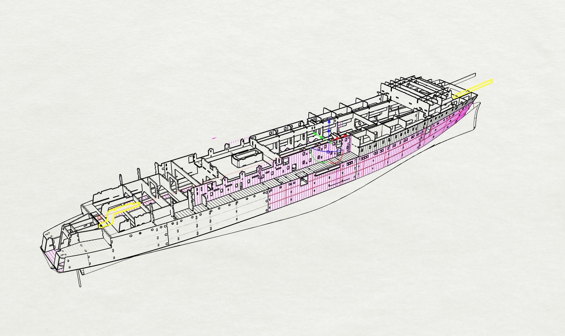
Thoughts so far? I am think of fitting the 2mm acrylic clear into the 2mm ply holes in the hull at this stage flush as the .4mm plates have the actual openings in them 1.5mm smaller and proper size. I estimate that that is 3 days work so far. The bow beyond the forward most bulkhead is bread and butter as well.
- 454 replies
-
- 3
-
-
- Union Steamship Company
- Stepcraft 840
- (and 3 more)
-
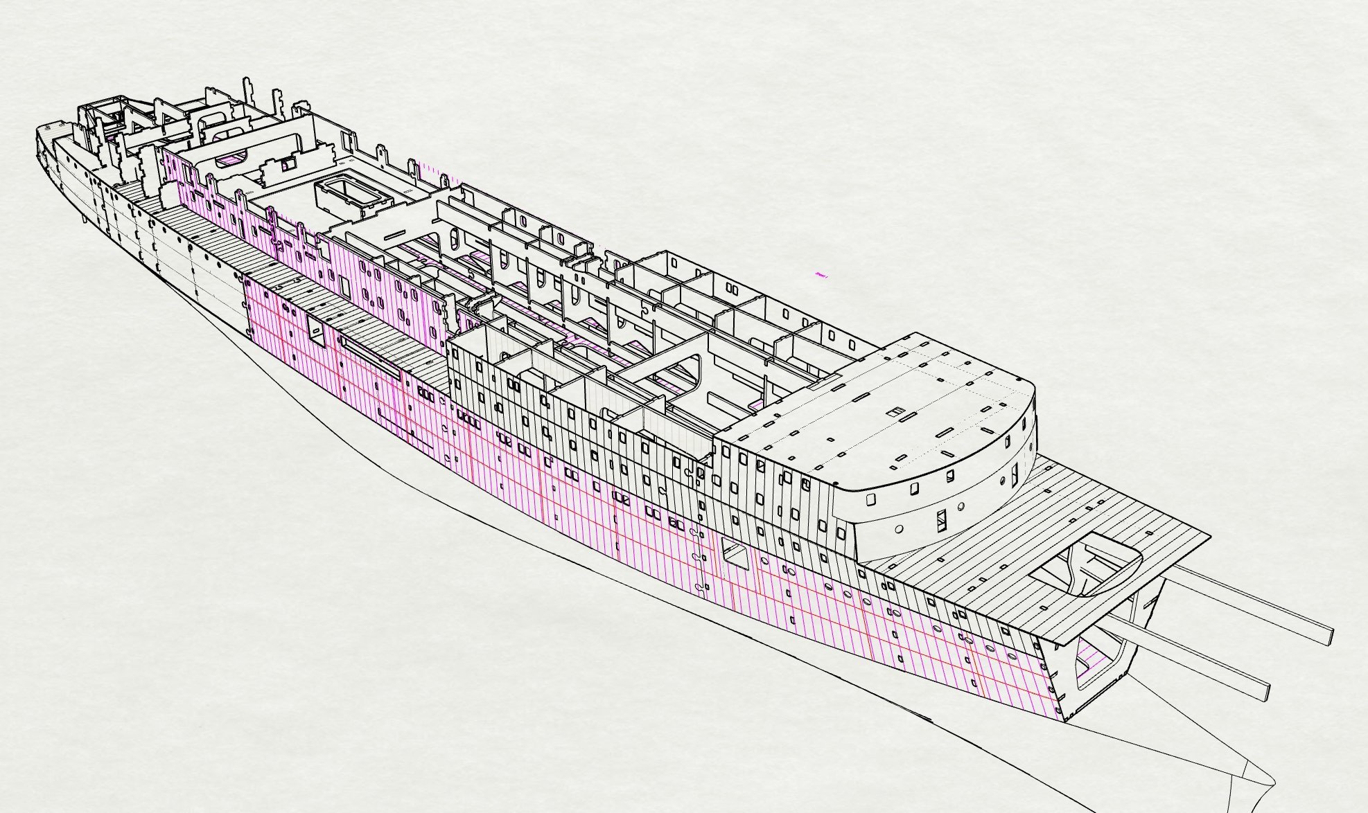
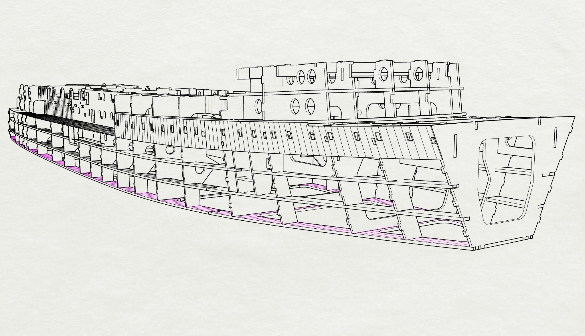
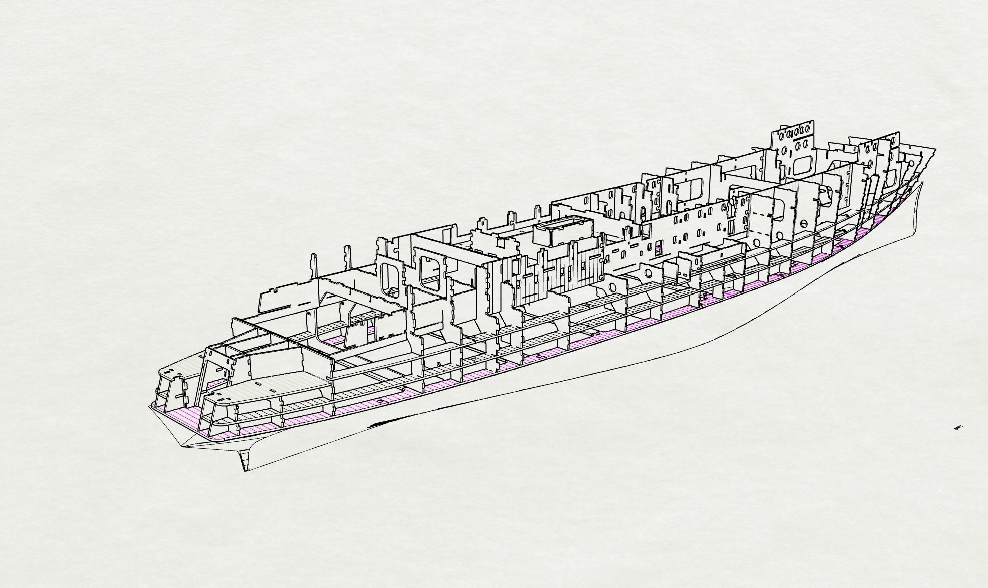
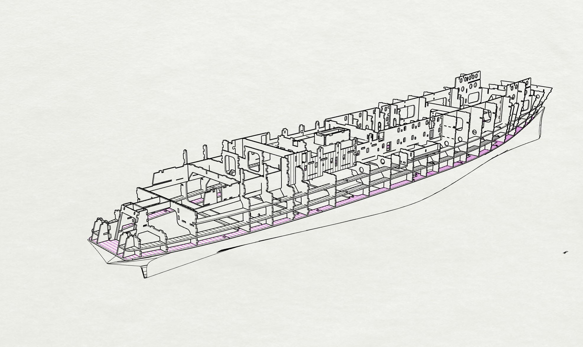
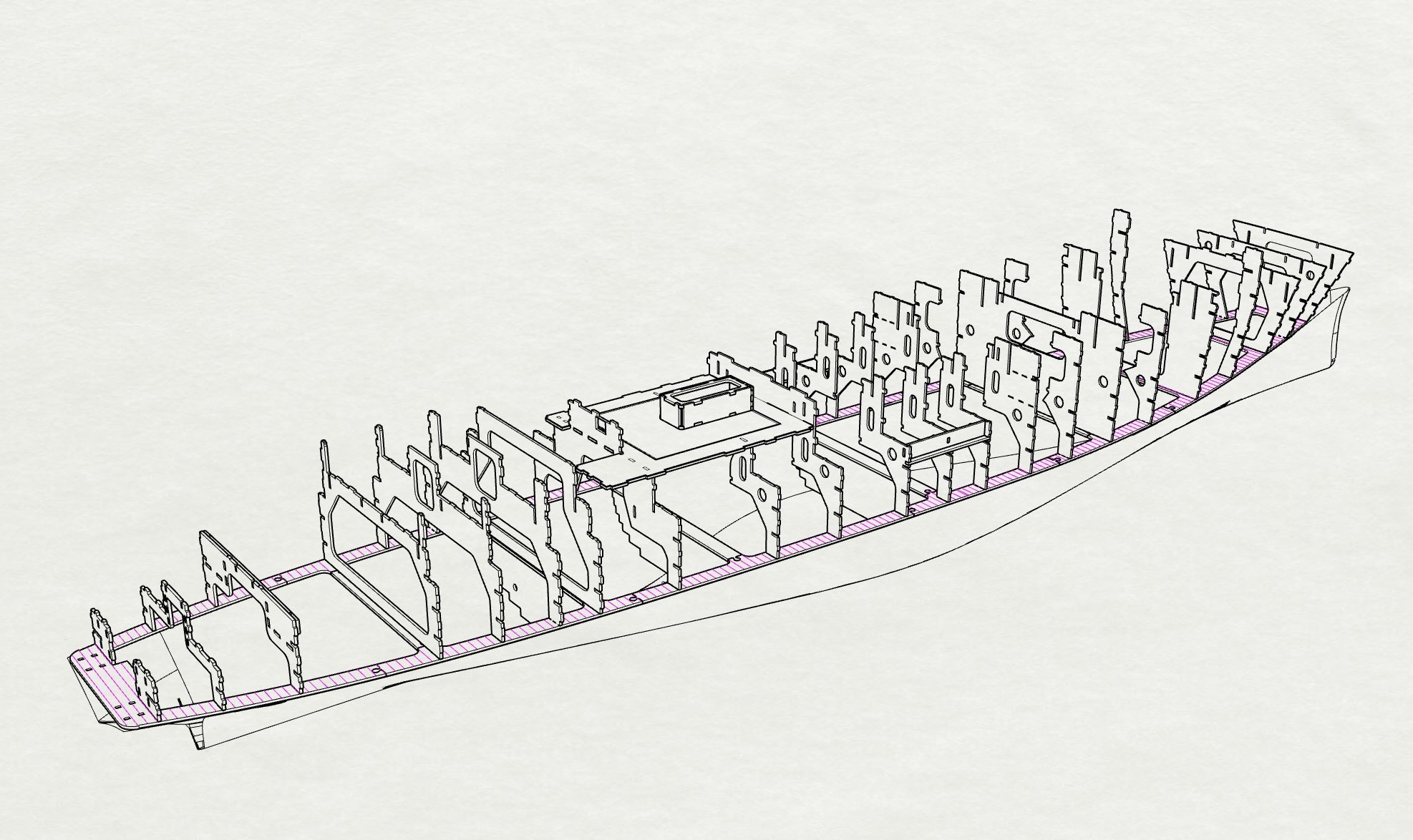
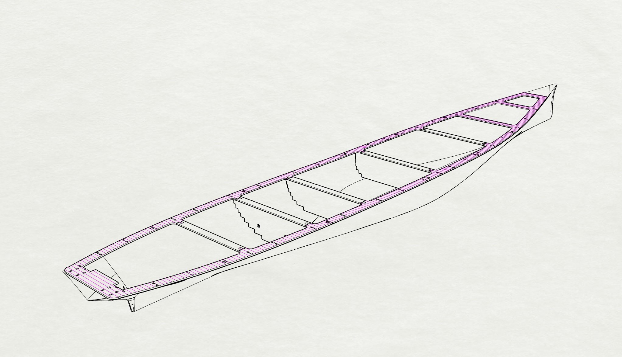
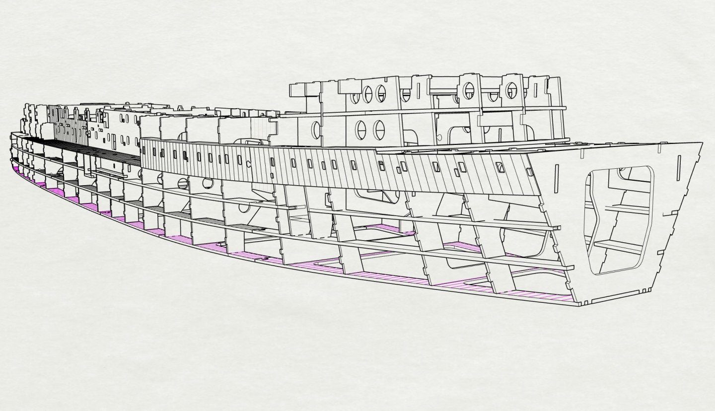
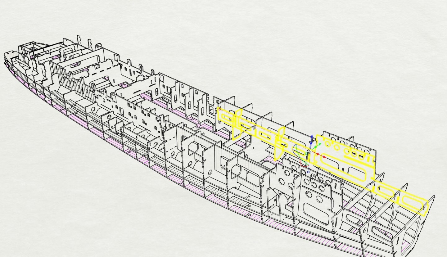
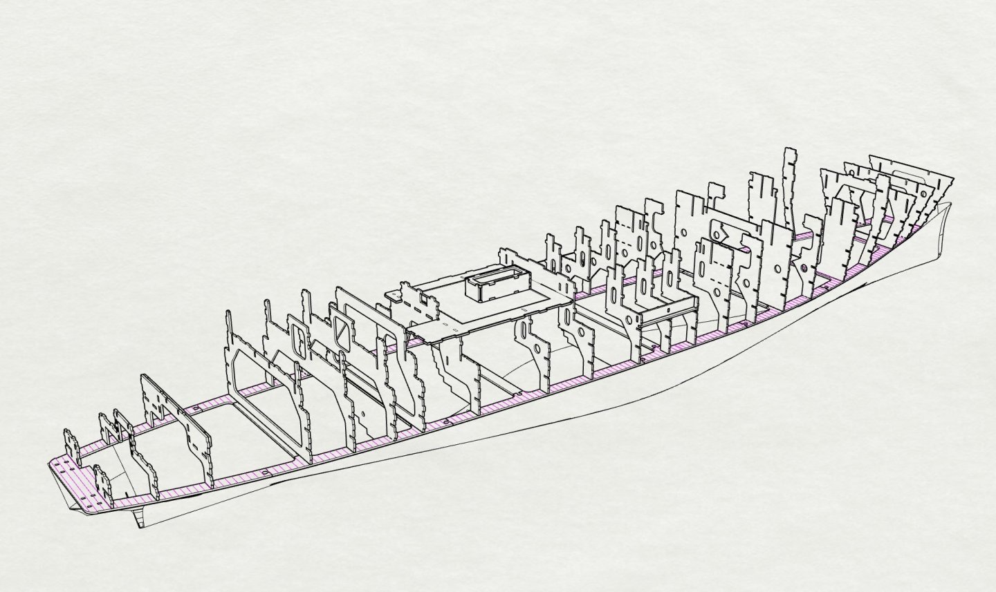
Step_16 Major Step Fitting Hull side panels along full hull, tenons should align everything and make hull rigid. all panels to have frames (pink) AND weld seams (red) marked on from shell expansion to aid fixing .4mm plates to this surface
- 454 replies
-
- 8
-
-
- Union Steamship Company
- Stepcraft 840
- (and 3 more)
-
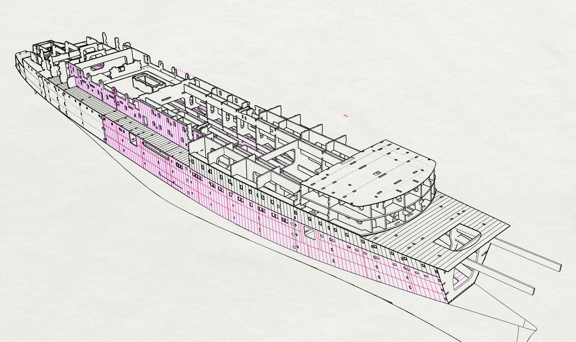
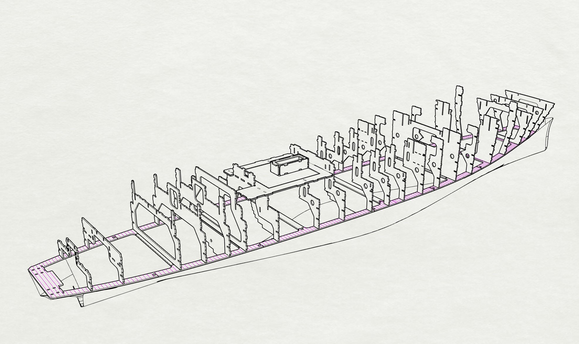
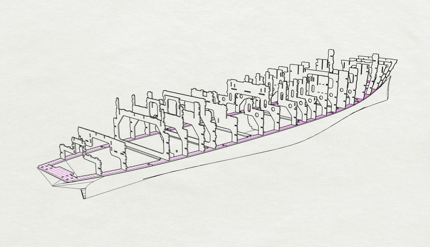
Step 15 Fitting 2mm side panels to hull on C deck, this must be done first as other overlap it
- 454 replies
-
- 4
-
-
- Union Steamship Company
- Stepcraft 840
- (and 3 more)
-
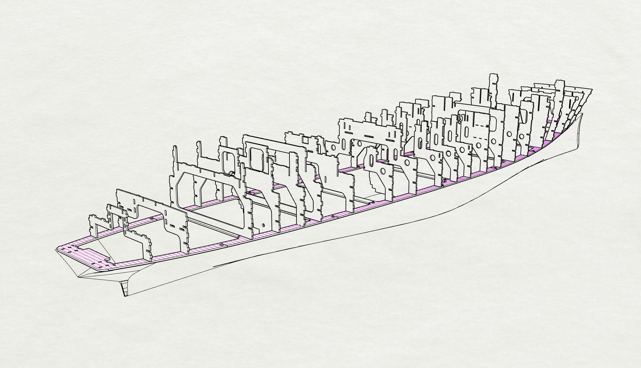
Step_14 Fit 2mm C deck panels to lock all frame heads in place
- 454 replies
-
- 5
-
-
- Union Steamship Company
- Stepcraft 840
- (and 3 more)
-
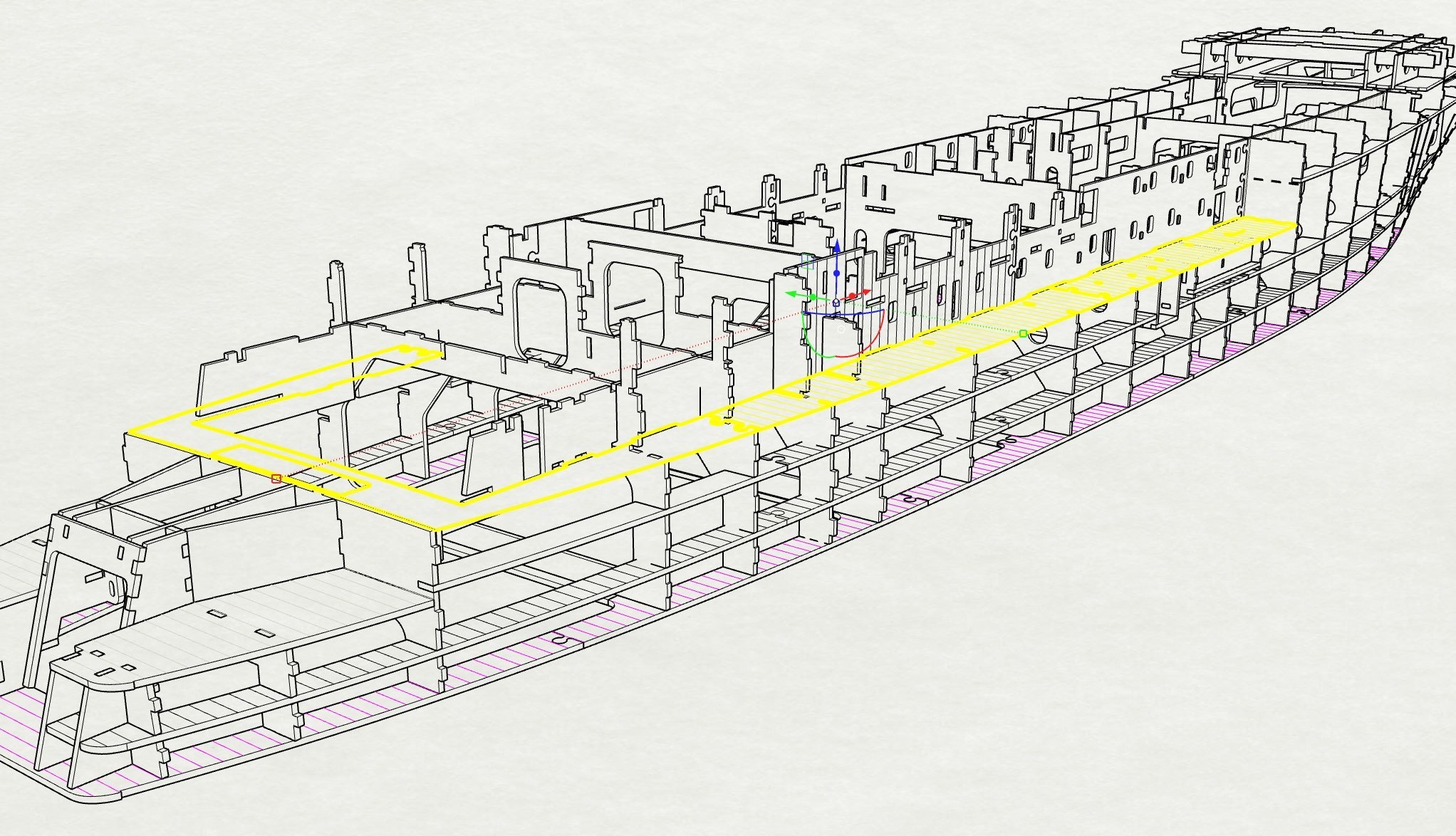
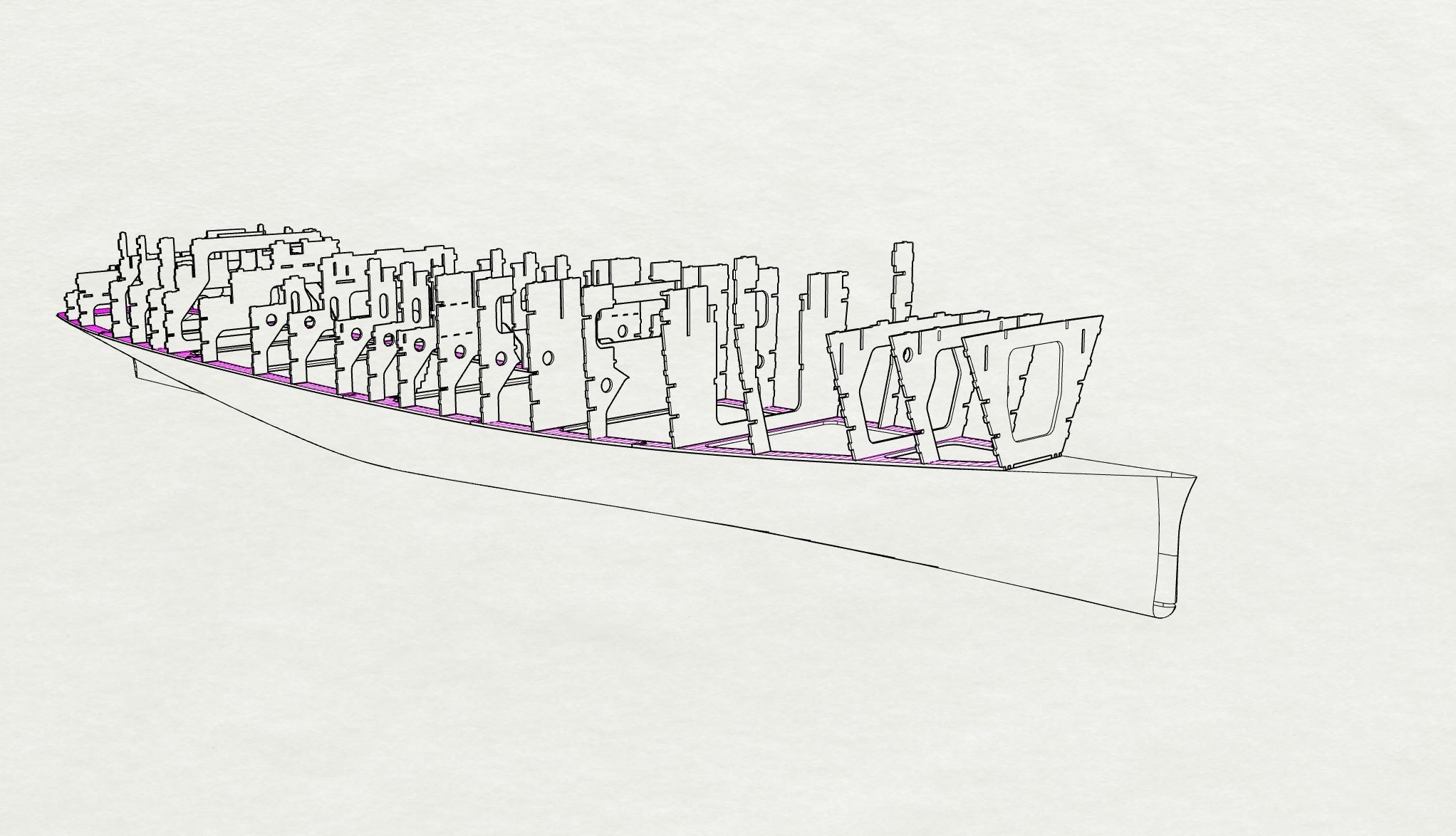
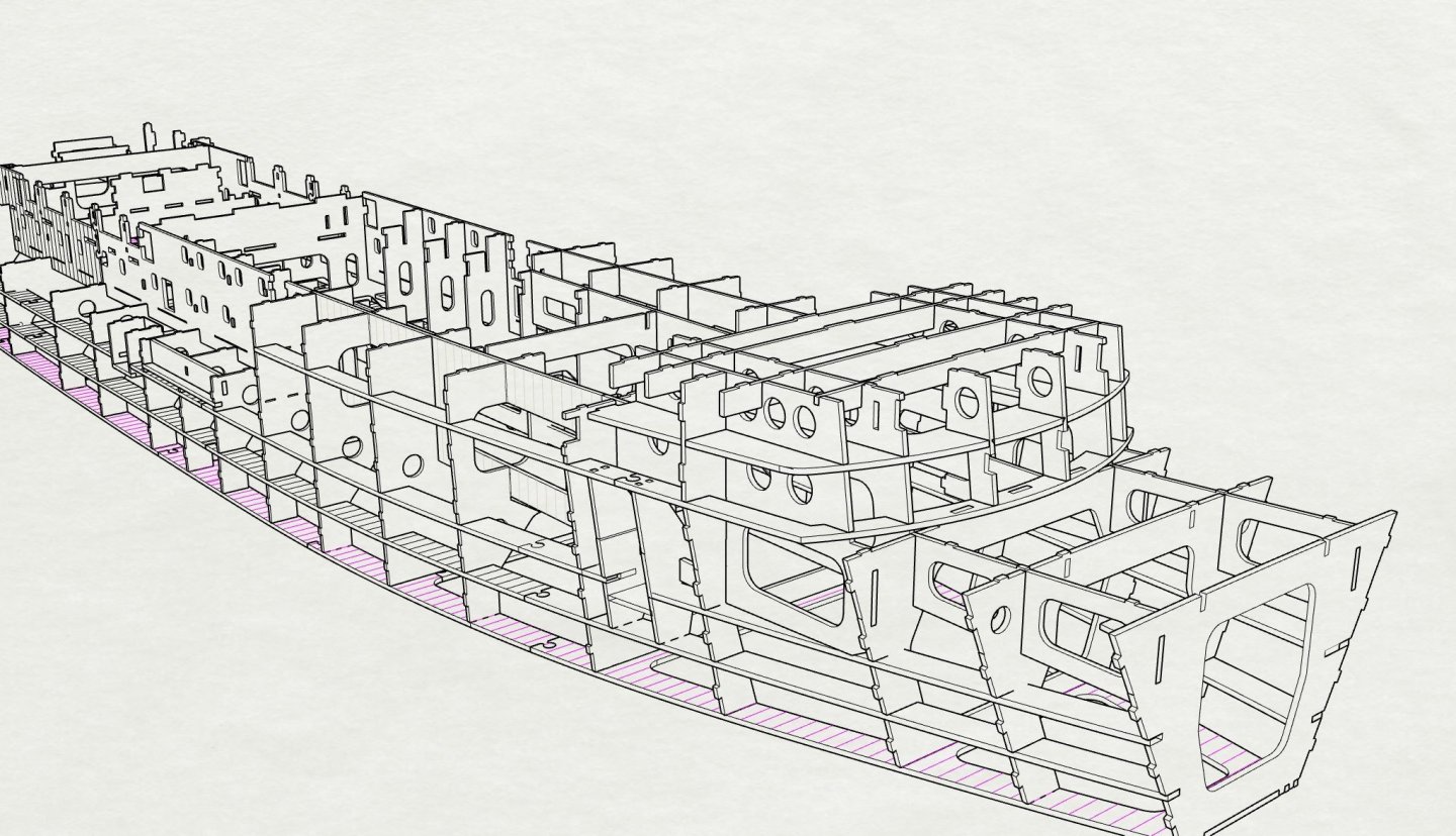
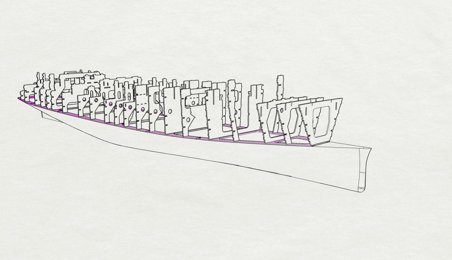
Step_13 Fit forward deck beams and superstructure webs
- 454 replies
-
- 4
-
-
- Union Steamship Company
- Stepcraft 840
- (and 3 more)
-
Step_11_Fit forward Longitudinals and inner partial frames
- 454 replies
-
- 5
-
-
- Union Steamship Company
- Stepcraft 840
- (and 3 more)
-
Step_10 Assemble Forward longitudinals against straight edge
- 454 replies
-
- 4
-
-
- Union Steamship Company
- Stepcraft 840
- (and 3 more)
-
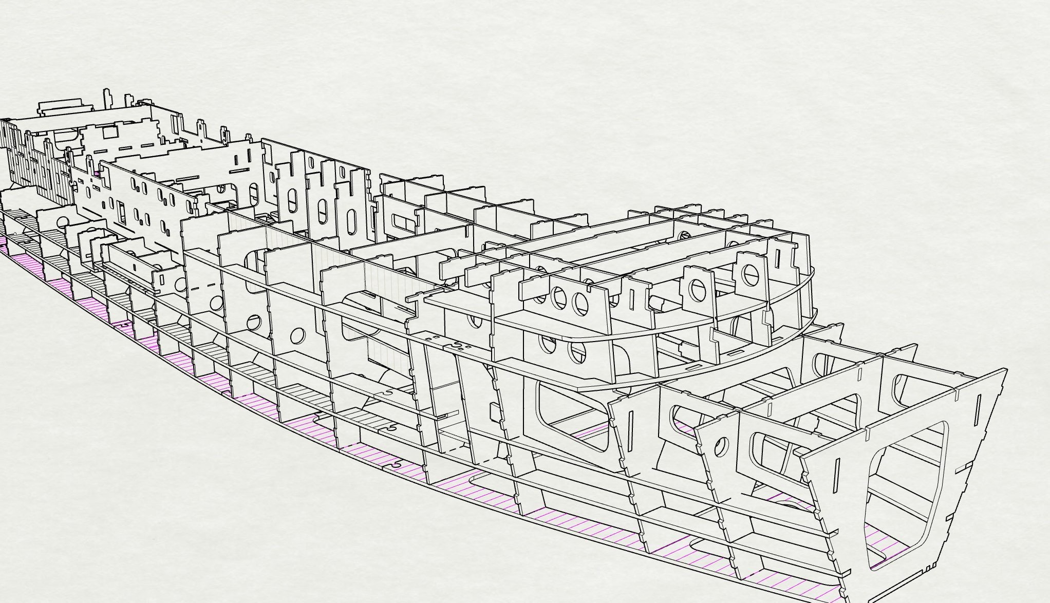
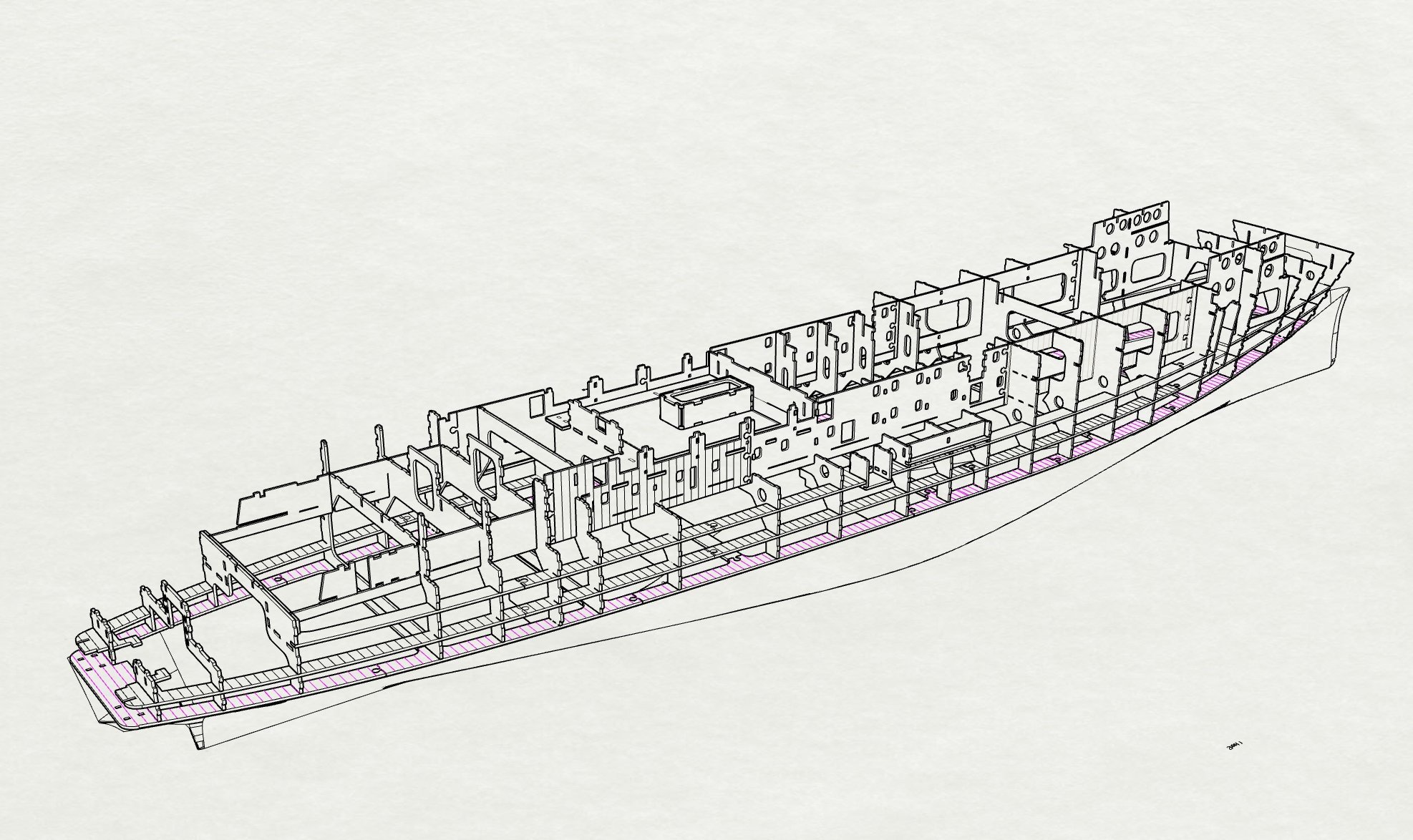
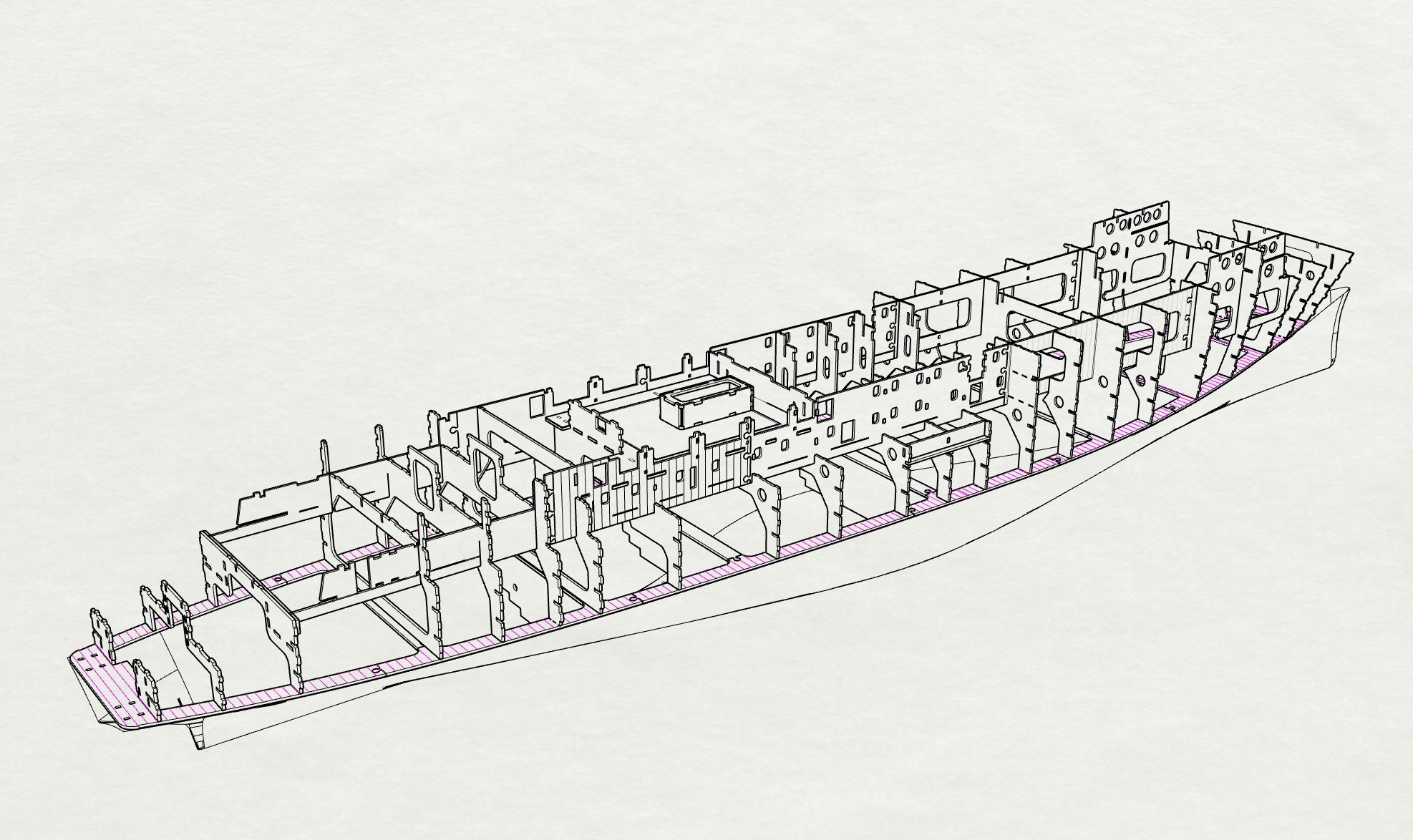
Step_09_Fitting of Mooring decks and angled bulkhead

- 454 replies
-
- 6
-
-
- Union Steamship Company
- Stepcraft 840
- (and 3 more)
-
Step_08 addition of Stern webs and stern door
- 454 replies
-
- 5
-
-
- Union Steamship Company
- Stepcraft 840
- (and 3 more)
-
Step_07 Assemble main Hull stringers

- 454 replies
-
- 5
-
-
- Union Steamship Company
- Stepcraft 840
- (and 3 more)
-
Step_06_Install main Longitudinals into frames

- 454 replies
-
- 6
-
-
- Union Steamship Company
- Stepcraft 840
- (and 3 more)
-
Step_05 addition of stern half bulkheads, frame doubler to allow change in deck thickness and inside of tonnage openings midships
- 454 replies
-
- 4
-
-
- Union Steamship Company
- Stepcraft 840
- (and 3 more)
-
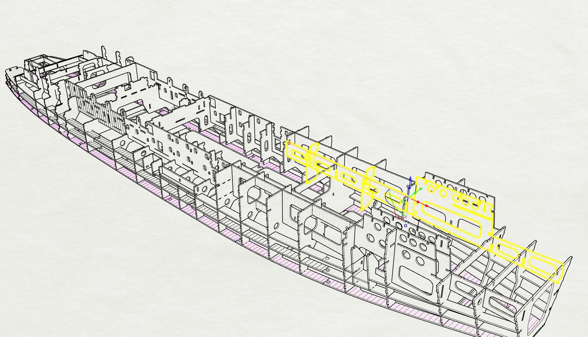
Step_04 Slide Assemble SmokeRoom Floor,Hatch and Uptake casing.

- 454 replies
-
- 7
-
-
- Union Steamship Company
- Stepcraft 840
- (and 3 more)
-
Step_03_Assembly of Main Longitudinals, check overall length for any compounding error and correct. Assemble with bottom edge against a straight edge.
- 454 replies
-
- 6
-
-
- Union Steamship Company
- Stepcraft 840
- (and 3 more)
-
Step_02_fitting of main frames into tenons in foundation plate.
- 454 replies
-
- 9
-
-
- Union Steamship Company
- Stepcraft 840
- (and 3 more)
-
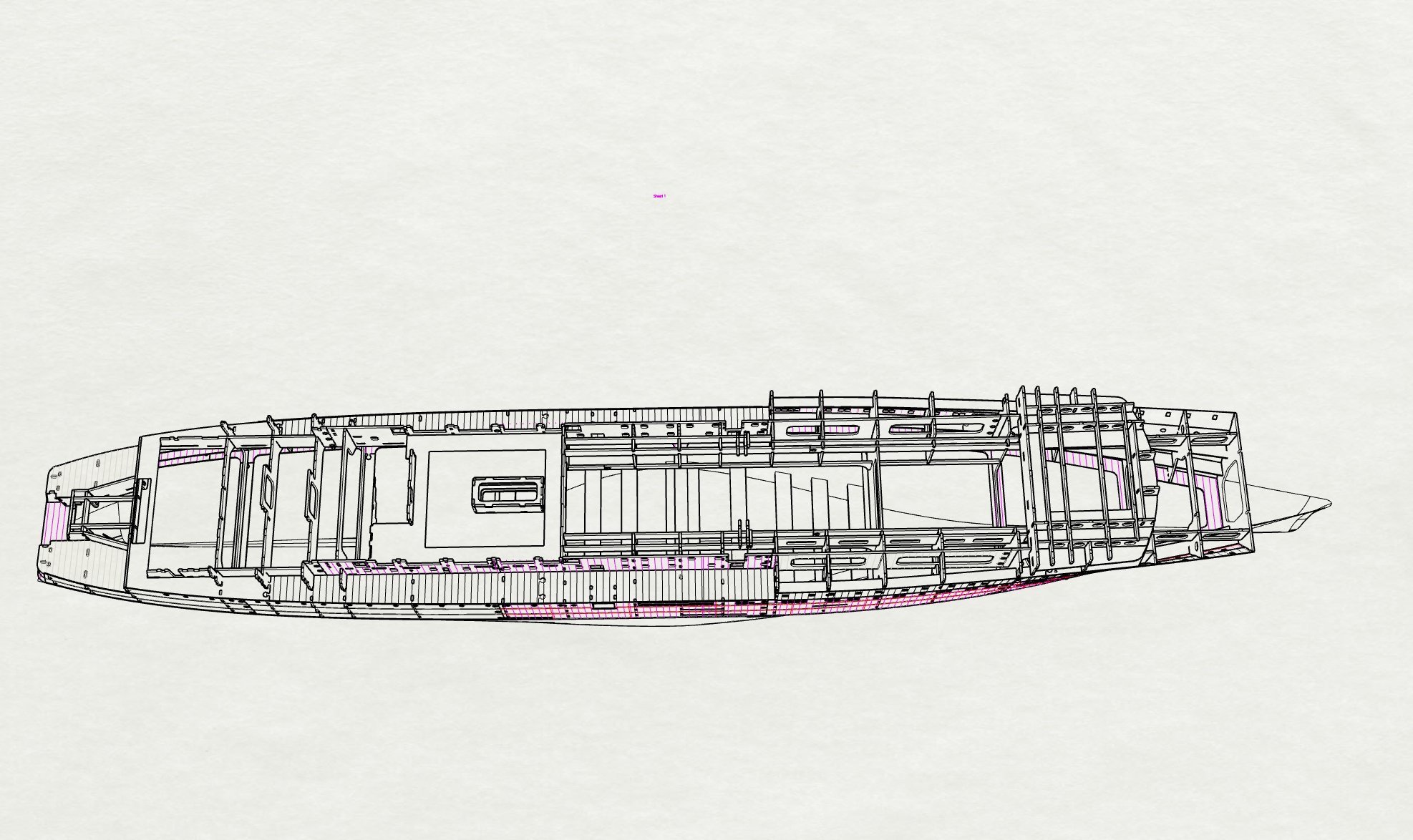
Just going to post my "instruction manual" pages here in case its of interest while I get into my head the assembly order Step 1 - foundation plates assembled and glued to top of bread and butter lower hull.

- 454 replies
-
- 5
-
-
- Union Steamship Company
- Stepcraft 840
- (and 3 more)
-
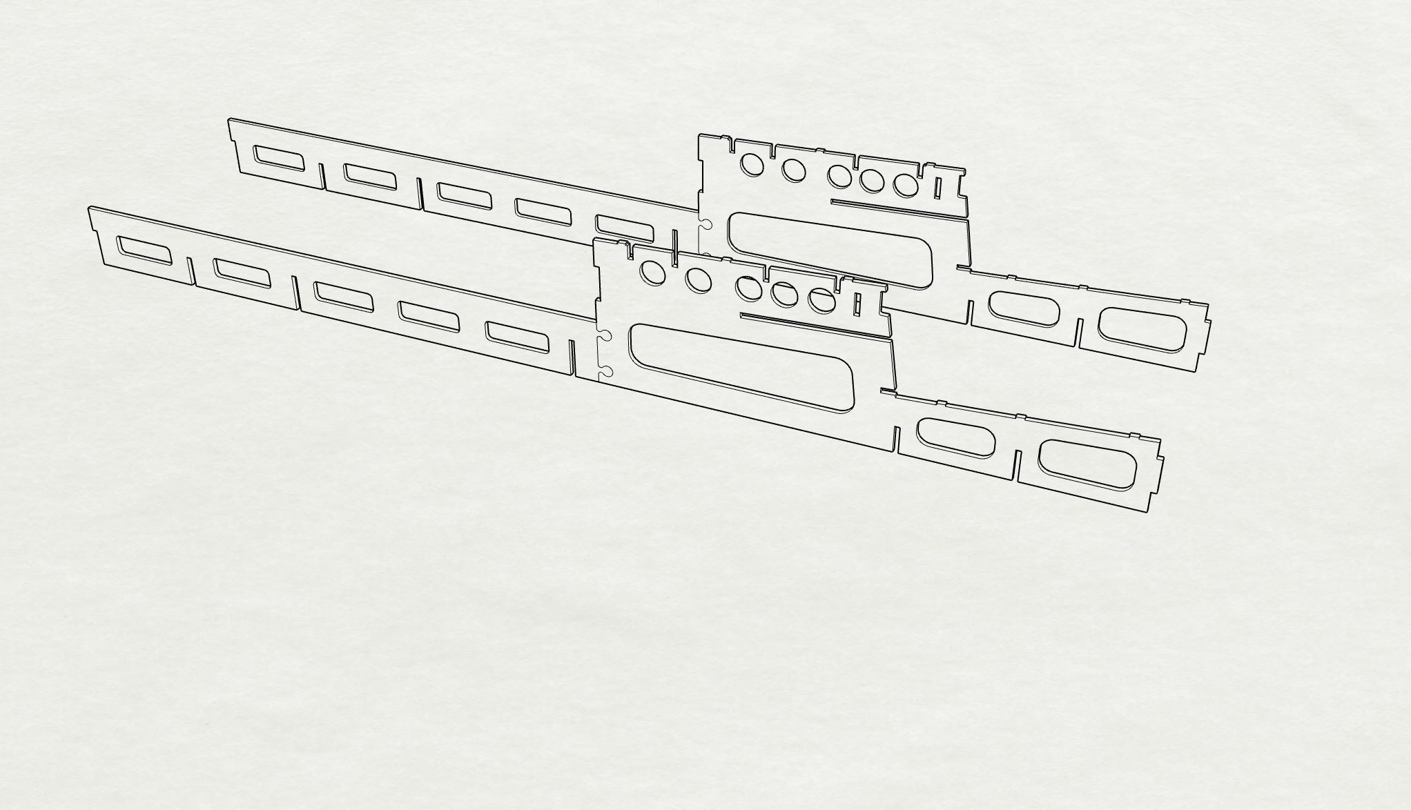
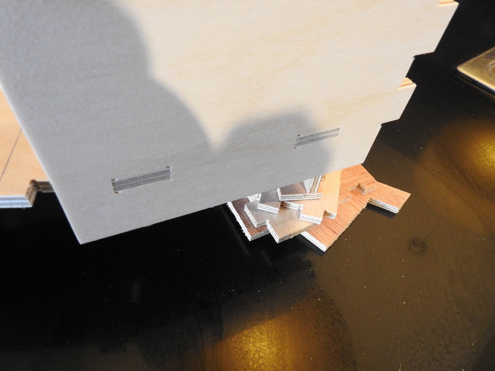
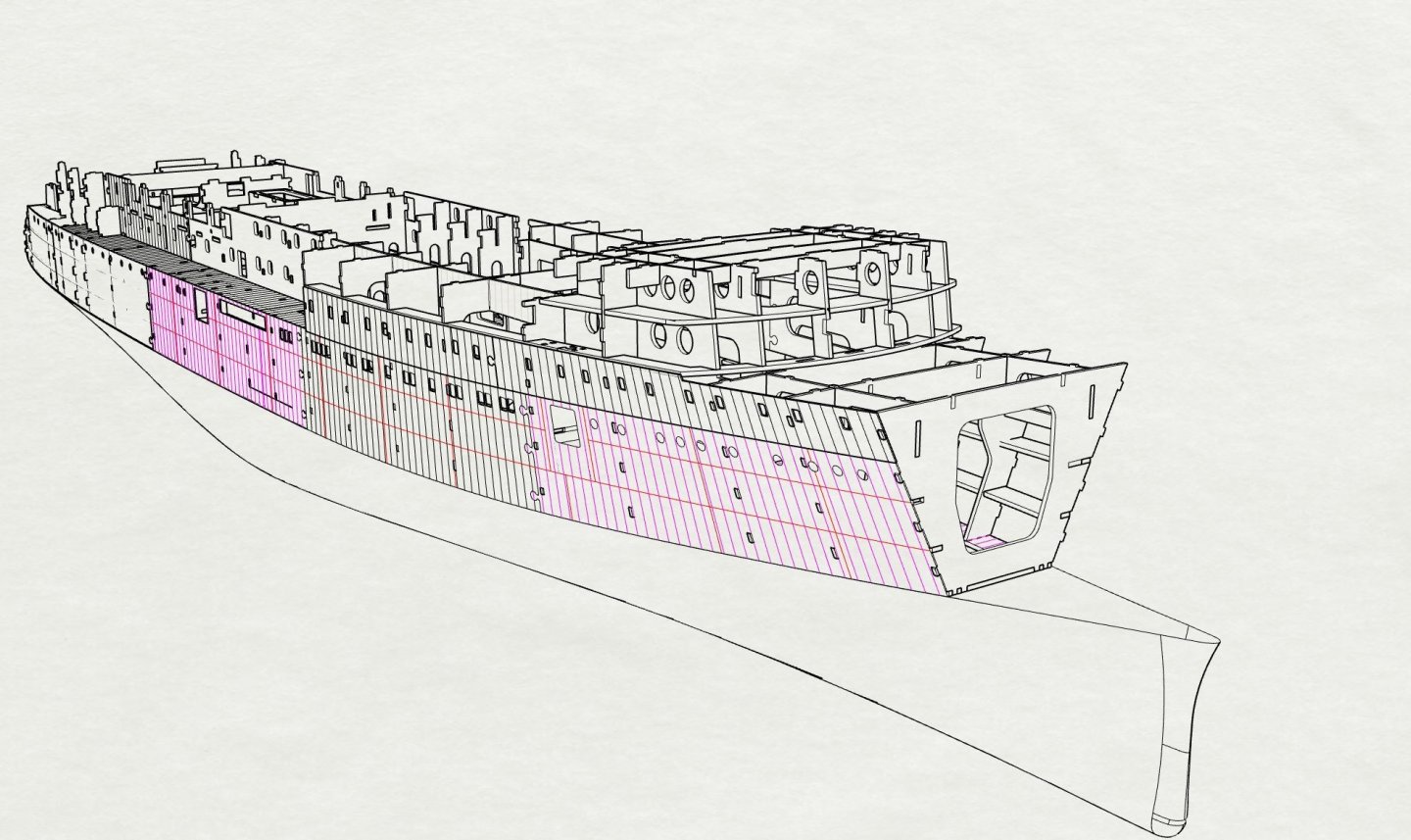
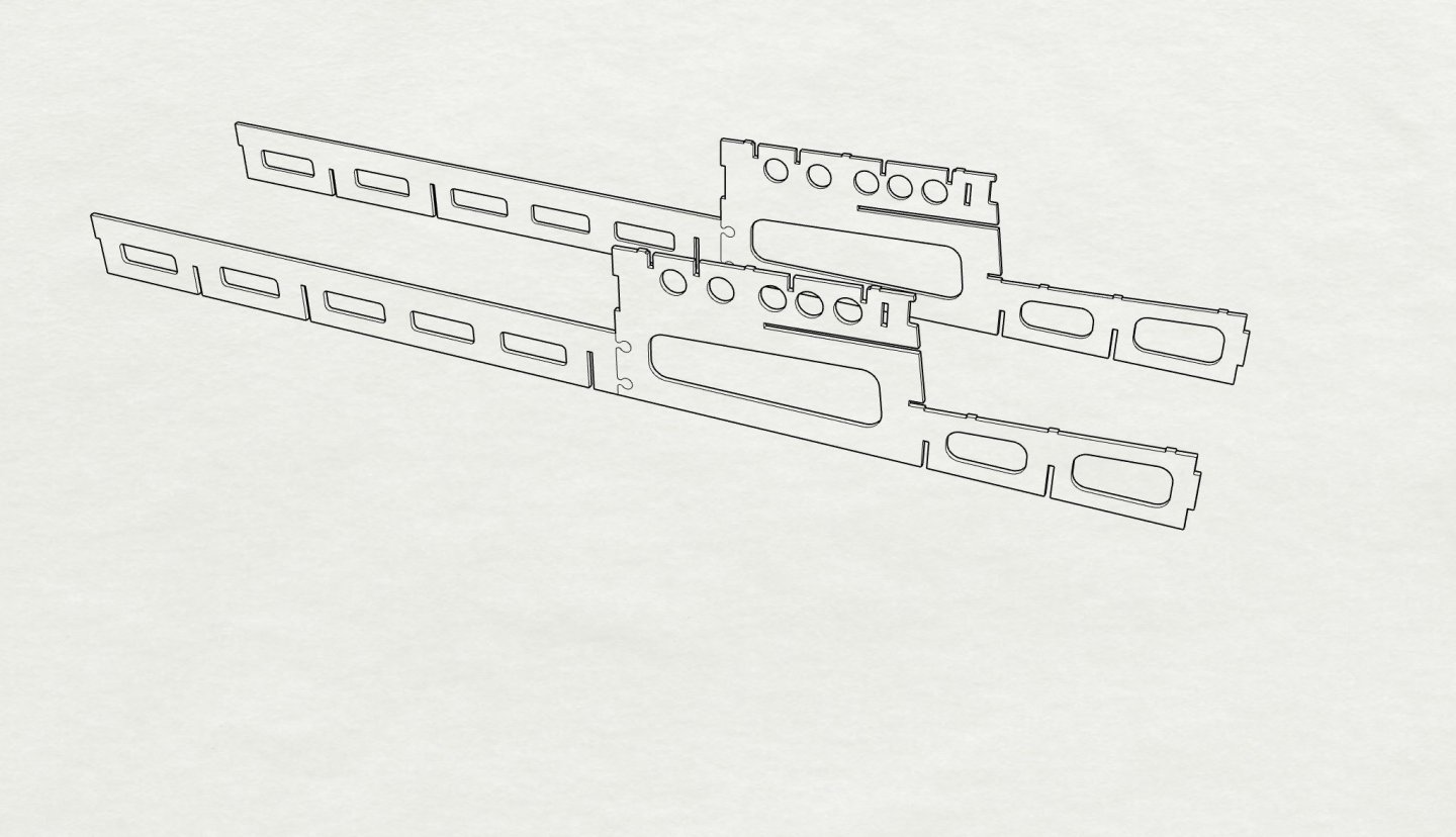
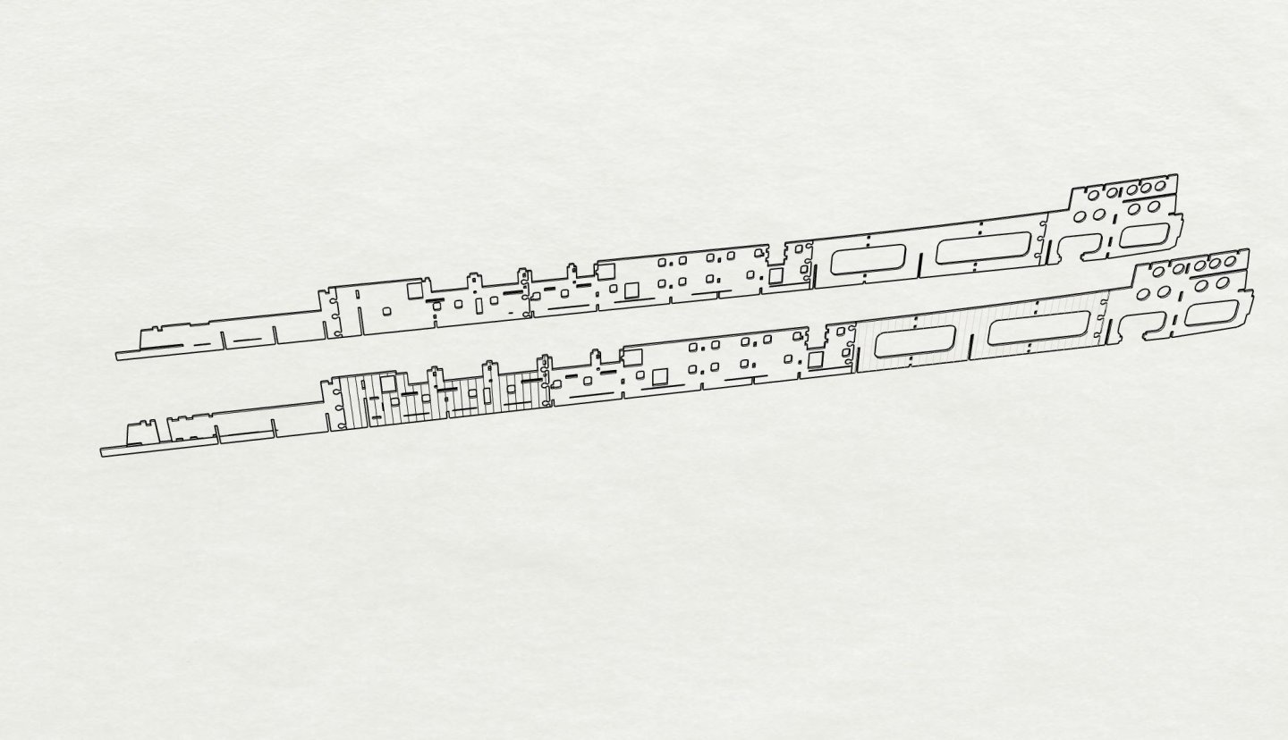
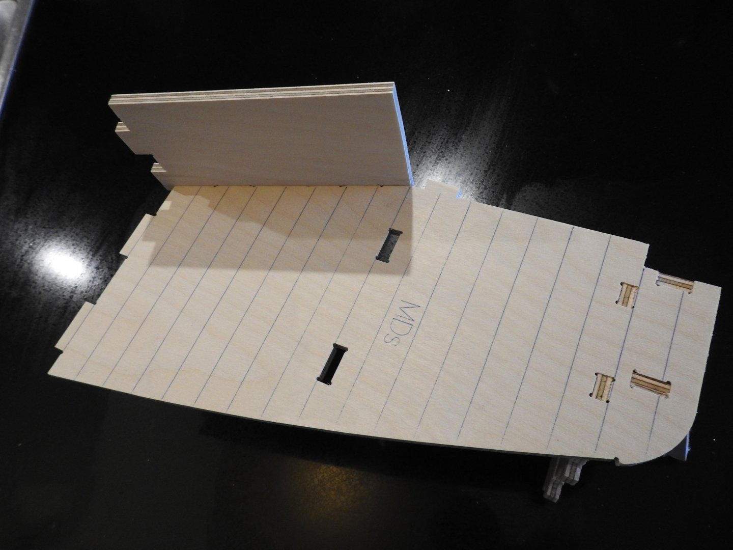
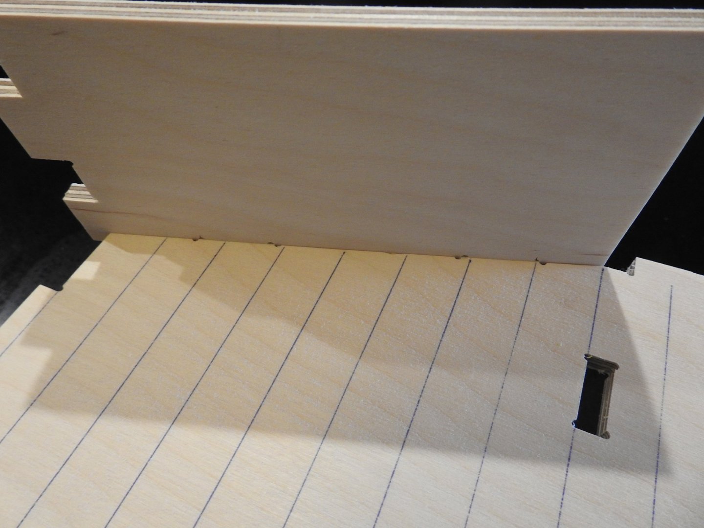
Here is a couple of parts to show the accuracy of the joints and how it was prepared in 3d to be transferred to 2d and on to CNC I then cut on the CNC And after sanding the sheet and cleaning up tabs we get parts that fit like this. Notice the corners are "dogboned" to clear the radius from the corners of the holes, the pen work is also done on CNC with a pen attachment so frame lines are perfect


- 454 replies
-
- 11
-
-
- Union Steamship Company
- Stepcraft 840
- (and 3 more)
-
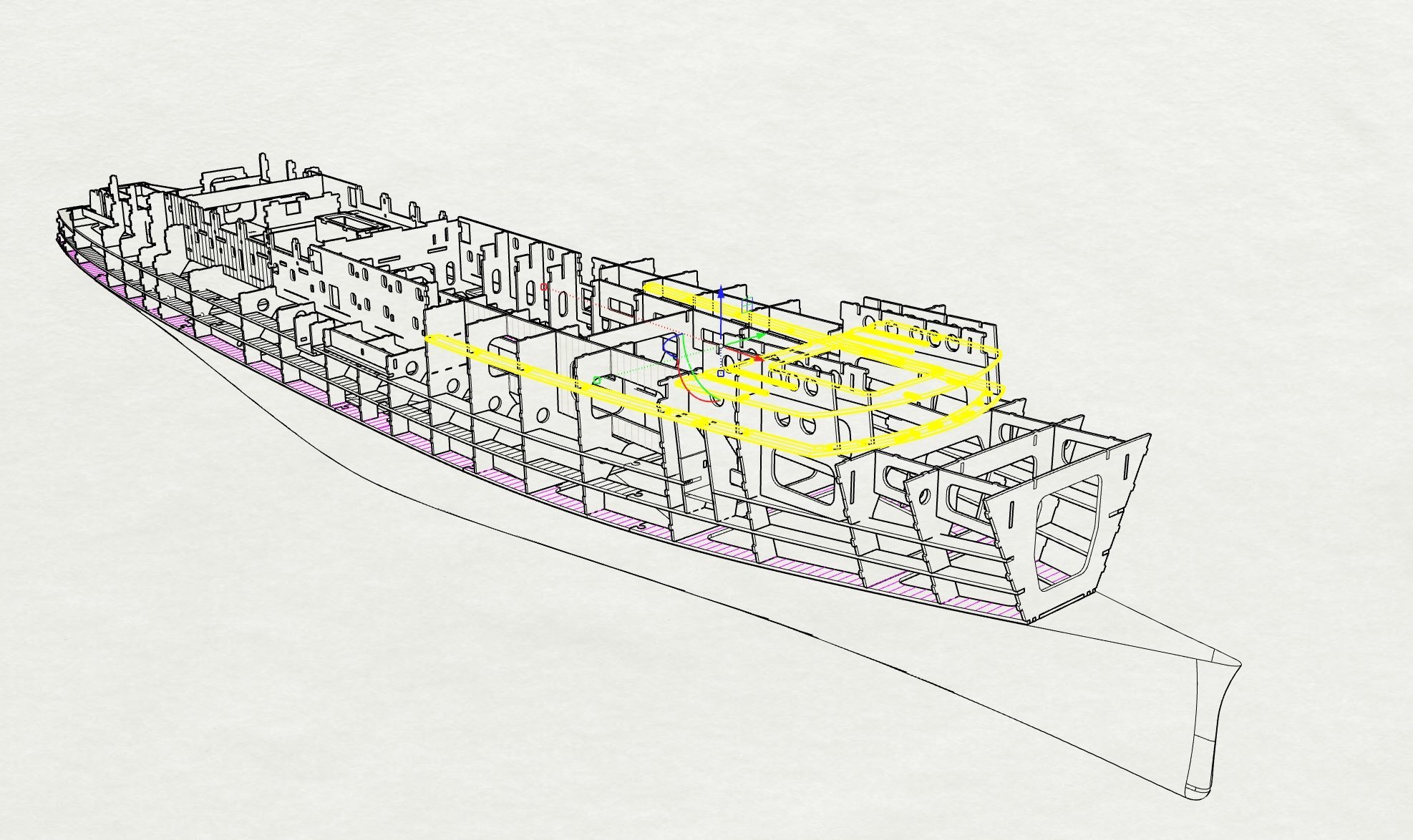
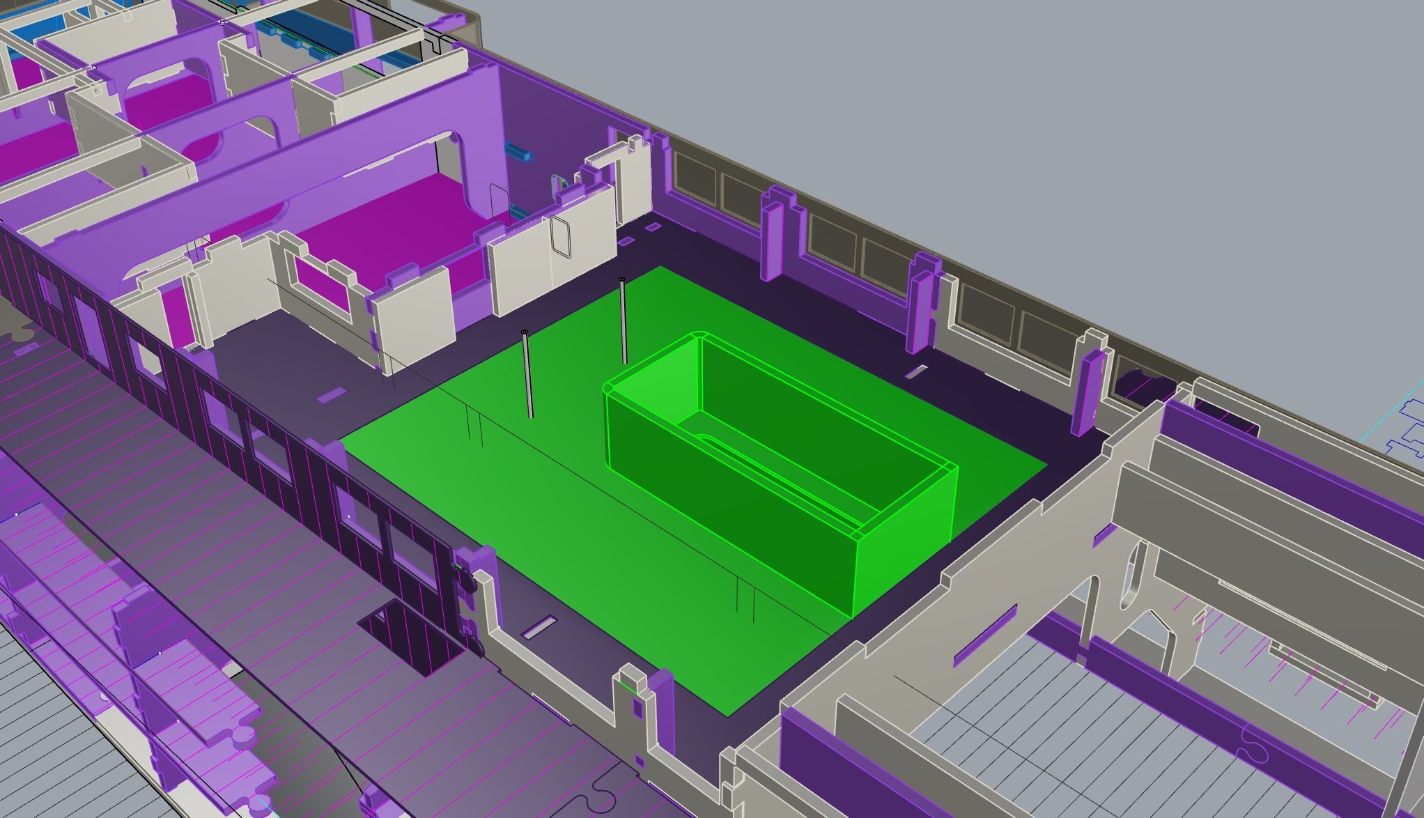
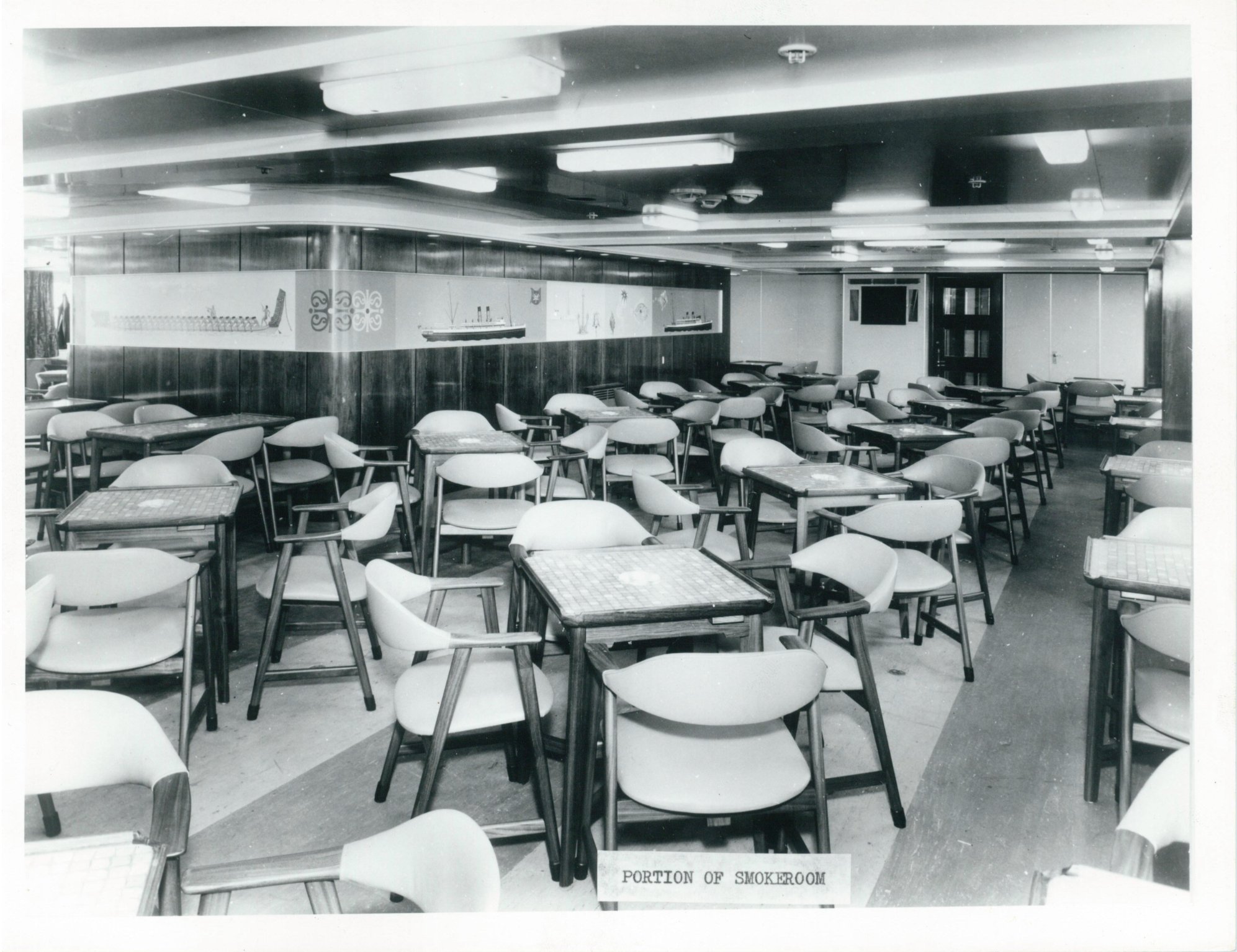
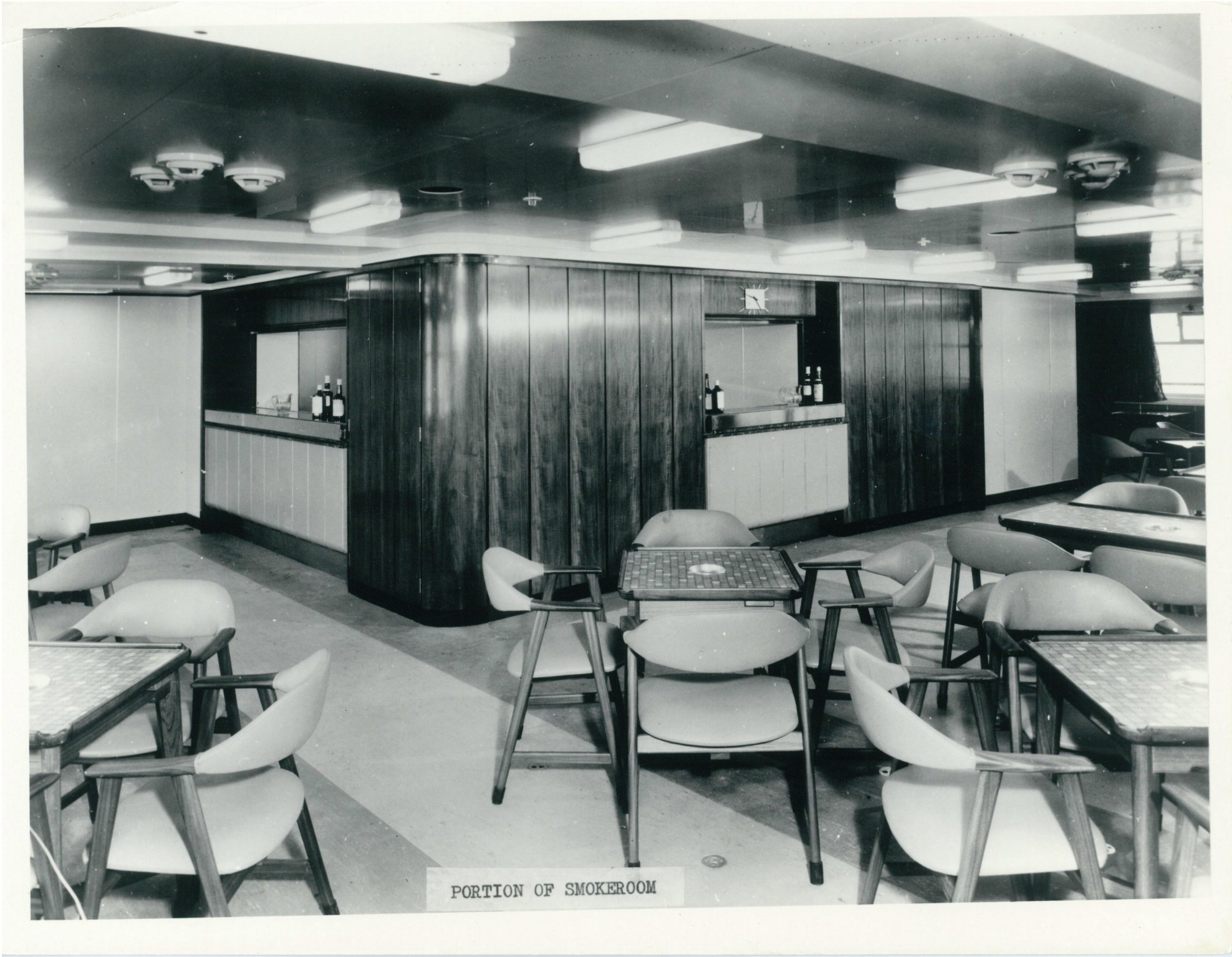
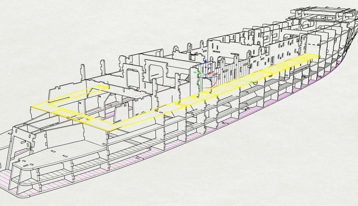
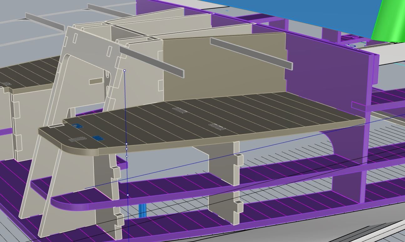
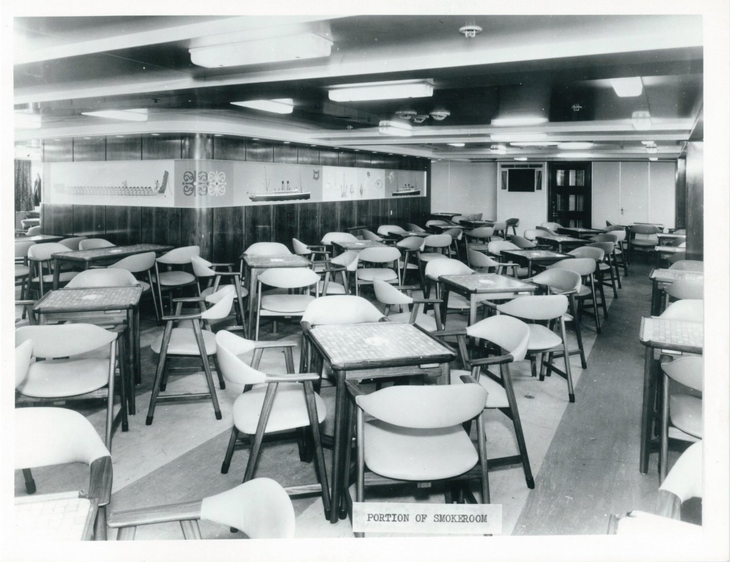
This image shows the Smoke room, one of the passenger areas that needs to be fitted out due to large windows, note the green area which is removable floor to access the spaces under, the join in the floor falls between tables and chairs. The engine casing will support the ceiling which is also part of the removable assembly that lifts out. I have added a photo of the space so you can get a feel for it.


- 454 replies
-
- 7
-
-
- Union Steamship Company
- Stepcraft 840
- (and 3 more)