HOLIDAY DONATION DRIVE - SUPPORT MSW - DO YOUR PART TO KEEP THIS GREAT FORUM GOING! (Only 20 donations so far - C'mon guys!)
×


Lecrenb
-
Posts
262 -
Joined
-
Last visited
Content Type
Profiles
Forums
Gallery
Events
Everything posted by Lecrenb
-
 So far, so good... now to finish shaping the pedestal portion, then I can cut in the viewing glass and lantern chimney...
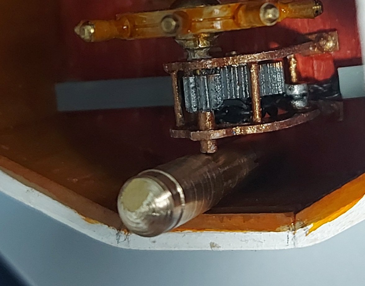
-
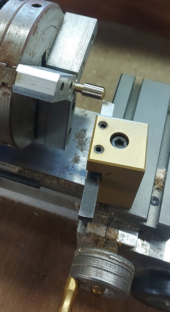
Here is the binnacle being roughed out on my Taig lathe... I'm taking it slow and easy, lots of checking with the micrometer to make sure it will be good for size and still fit the model! I only get one shot, if I screw up then I have to go get more brass rod! This is the ship's binnacle today... note the tight fit between the wheel and the wall... also the windows in this 1944 wheelhouse are smaller than the ones in the 1930 house that I am modelling. Also the gyro and voice pipe were not present in 1930. Thanks for looking in!
-
Good morning! Thank you for your interest in my St. Roch build, hope you are enjoying it!
Regards,
Bruce
-
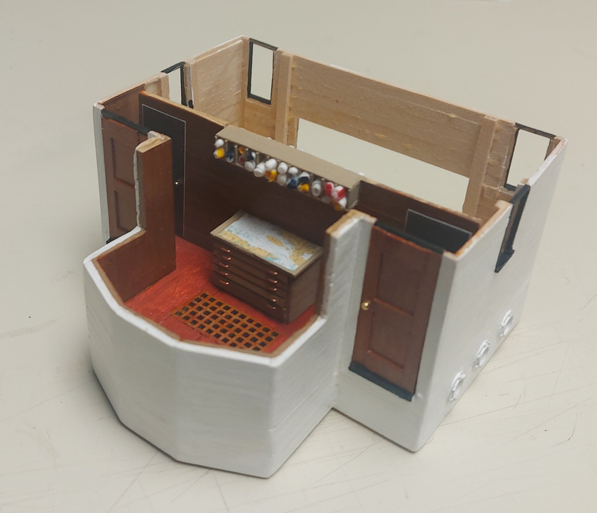
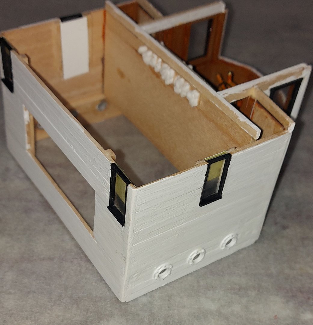
More progress on the deckhouse... the wheel is complete and installed, the grey covers are over the chains leading out to the rudder. The side walls are finished and glazed. I used plastic sheet cut from clamshell food containers, free and no hardship to provide for! I will install the front windows after I make the binnacle. I did measure twice, but fingers crossed that I left enough room for it between the wheel and front wall! Turning to the two cabins behind the wheelhouse, I glazed the windows and decided to finish them with pull down blinds. I did try several tricks using sea cabin pictures to give more of an idea of the interiors, but I was not happy with the results. I would also have had to install a floor to keep from looking through the windows down to the clerestory. The window blinds are left over from a Walthers model storefront kit that I built for my model railroad. Setting them a bit behind the glazing gives a decent 3 dimension effect. I have also started roughing out the roof, so once the wheelhouse front is finished I can put that on and attach the deckhouse to the ship!

- 368 replies
-
- 12
-

-

-
Good question... Captain Larsen refers to a system of bells used to signal the engine room... presumably this was either magneto operated like an old telephone ringer (because St. Roch had no electric power unless the auxiliary engine was running), or pull cord operated like Edwardian era stately homes, used for summoning servants. Either way, or if a third system was used, Captain Larsen reported the bell system was unsuitable because the engine commands came in quick succession as the ship maneuvered through the pack ice, and the engineer at the throttle often got confused as to what was required from the engine! A telegraph was fitted in 1940, also a voice pipe, although I believe this led up to the open pilotage above the wheelhouse. Unfortunately the historic record is silent, or unclear, on many of these details. Thanks for your interest!
-
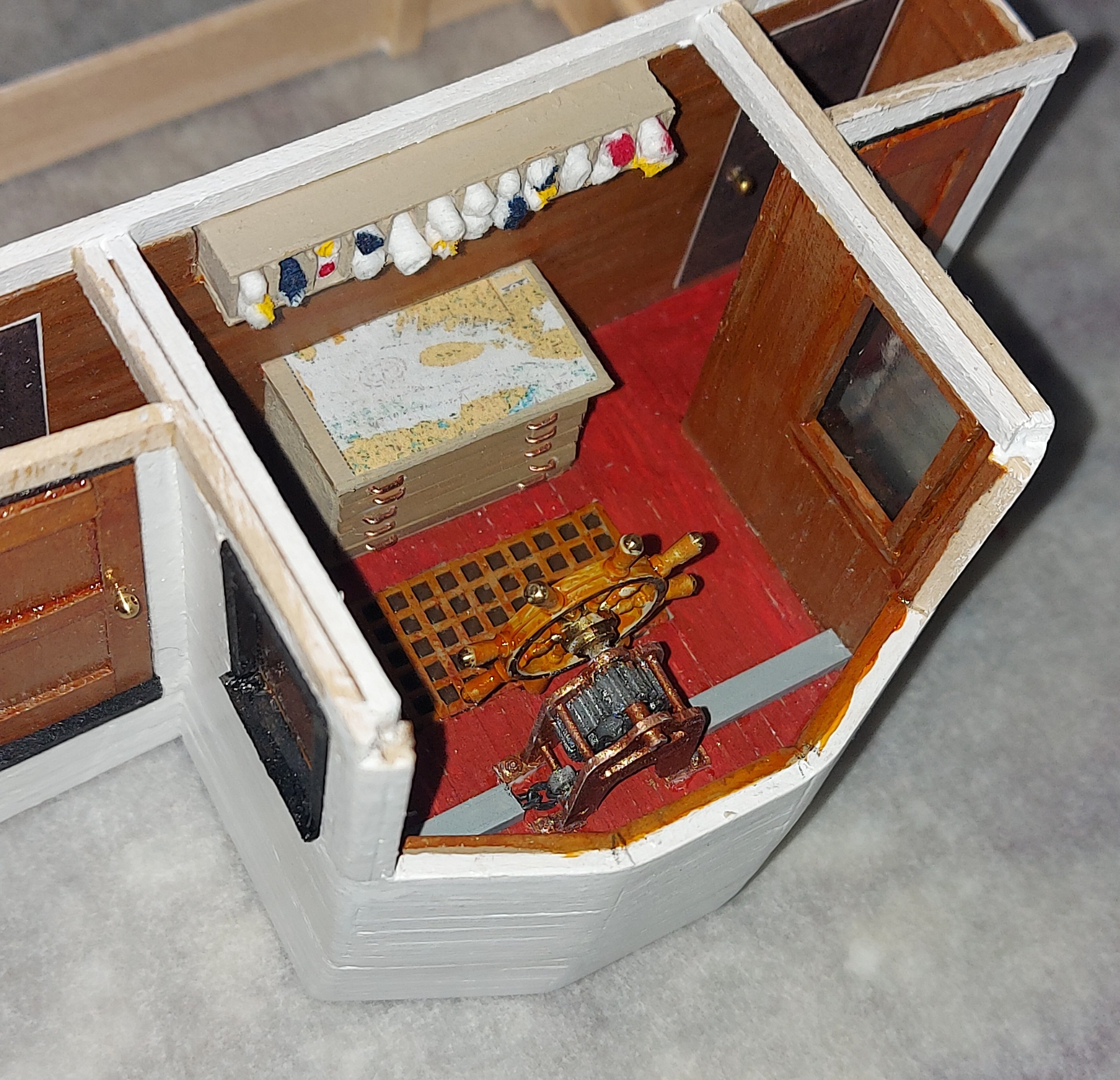
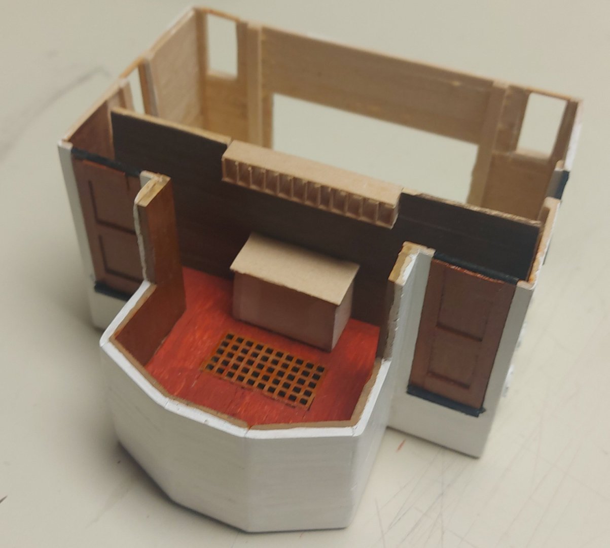
Thank you very much... I wanted to put realism into this space since you'll be able to see into the front windows. I used St. Roch's chart table and flag cuddies as they appear today. I am thinking they are original and were re-used during the various deckhouse rebuilds. The chart is Queen Maud Gulf, waters that St. Roch sailed during her Arctic voyages.
-
More progress... the flags and chart table are complete... The interior doors into the cabins are my best guess. Photos clearly show only the two forward structure doors that presumable lead to the wheelhouse. It does not make sense to walk through the cabins to get to the wheel, therefore there must have been some sort of interior access to the cabins. If I size the two new cabins equal to twice the size of the single original then you get the dimensions I have modelled. The wheelhouse is slightly larger but now there is space for the chart table and flags that were in Captain Larsen's original cabin. While conjectural, I think this layout is defensible absent any new information. The steering wheel mechanism is ready for paint... At this point it actually works, but once the paint goes on it will freeze the gears and pulleys in position. I'm thinking about how to tackle the glazing in the cabin windows... I don't like black rectangles, but there is no cabin interior, so I might put window shades on the inside of the glass. Another option might be to use internet photos of sea cabin interiors behind the windows; details won't be apparent but the eye will see there is something there. I use this method on my model railroad building interiors. If anyone looking in has other thoughts I'd certainly consider them. Nearly ready to attach this cabin module, then on to the lobby and head aft of the cabins. These are original from 1928, and were kept when the new cabin/wheelhouse was built in 1930.

- 368 replies
-
- 16
-
-
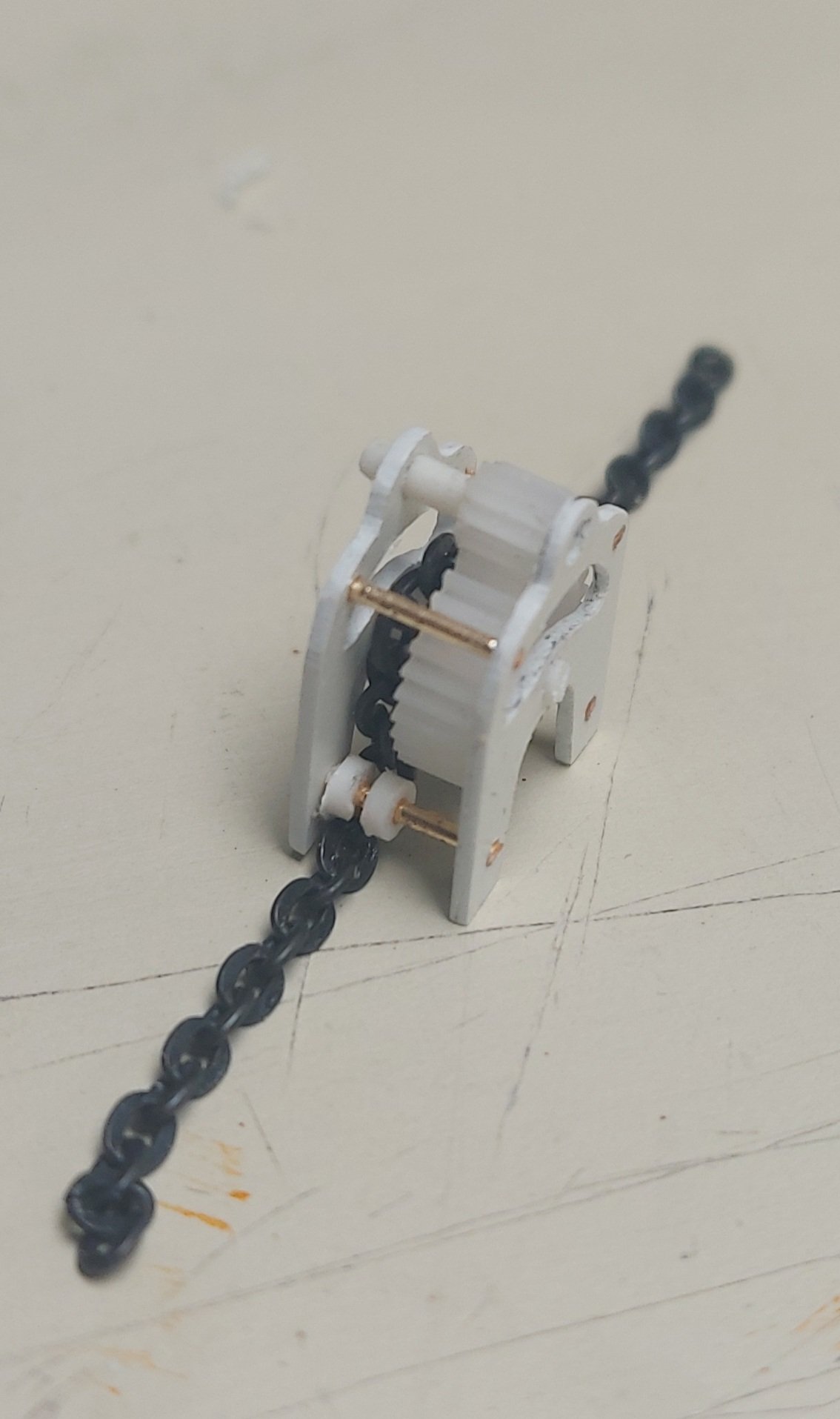
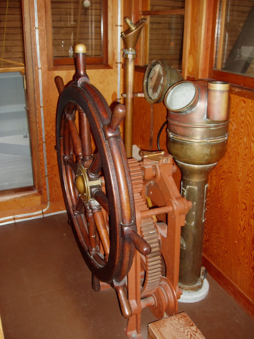
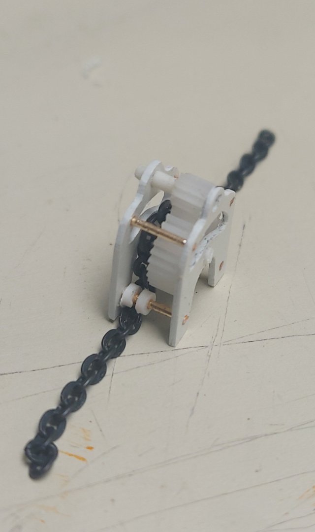
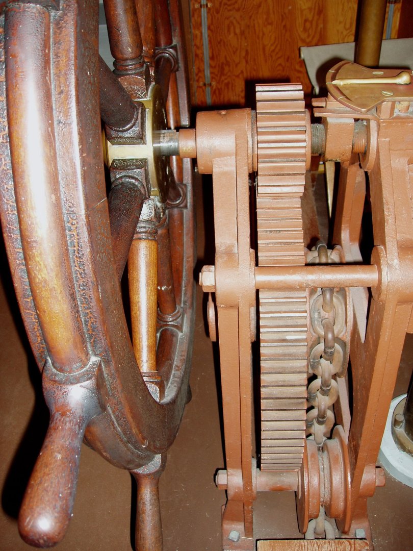
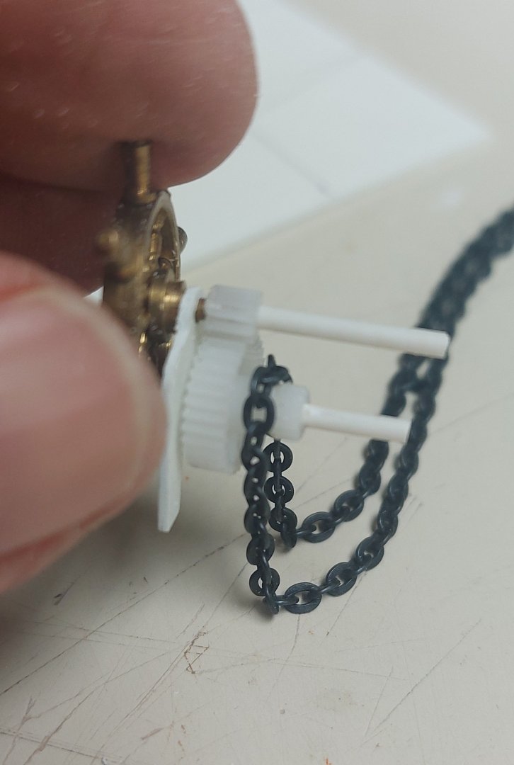
Work continues on the wheelhouse. I added the cuddies for the signal flags and the top on the chart table. finishing up tomorrow then I can start planning the roof and front windows... I had this brass wheel in my stash, and it turned out to be a near perfect match for St. Roch's... so I used it to start making the steering pedestal. The steering is manual using chains and cables back to the rudder quadrant. This is a picture of the actual wheel today, the gearing and chain gypsy are clearly visible... Here I have begun roughing out the pedestal... the gears are from a repair set for a Hi-Tec RC servo, and again are a near perfect size for the originals... I am cutting the channel for the chain into the nylon gear hub to replicate the gypsy. Hopefully in a day or two I will have the wheel completed and installed. Then I have to turn the compass binnacle on my lathe... fortunately St. Roch's wheelhouse is spartan. In the 1930s there was no voice pipe, gyro, or telegraph! Thanks for looking in and suggestions and comments are welcome!
- 368 replies
-
- 17
-
-
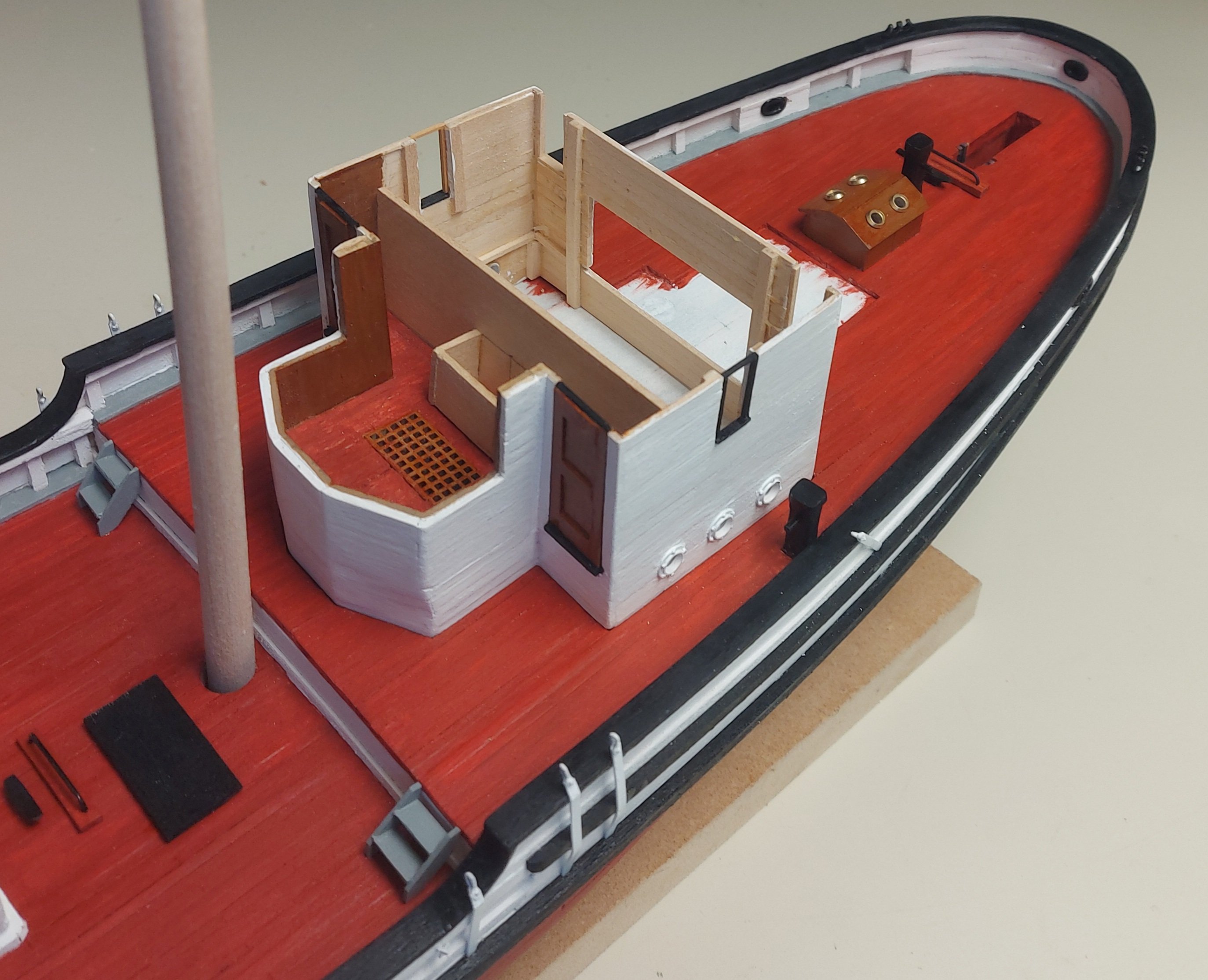
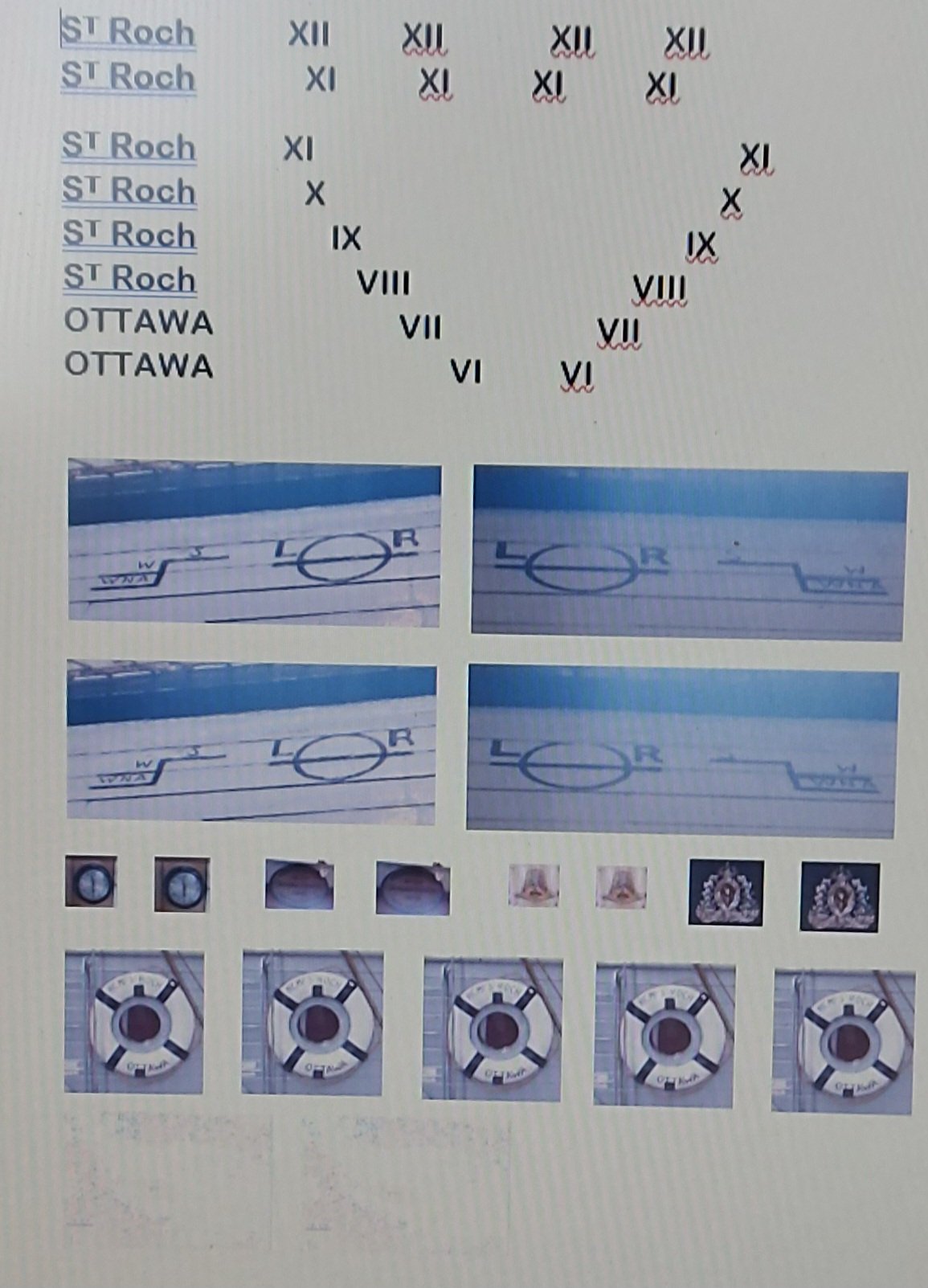
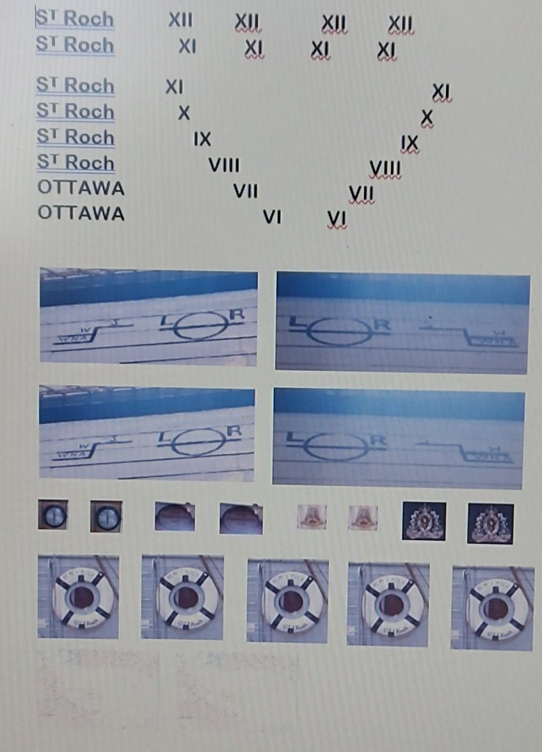
G'day all, and thanks again for looking in! I am continuing to plug away at the wheelhouse and cabin area... As you can see from the picture below I have got some paint on, some doors and window frames installed, and I'm working on the rear wall of the wheelhouse with the chart table roughed in. After considering the painting options I decided to go with the wood varnish, to match what appears to be her original deckhouse finish. I make this look by using Tamiya Brown (coloured wood stain works equally well) then overpainting with Tamiya Clear Orange. I am following the original 1928 plans for the wheelhouse layout, assuming the original was copied when it was moved forward, then the two cabins tacked on behind. I installed the three remaining fairleads and some poop deck fittings that are easier to put on now instead of trying to work around the deckhouse. I've also set up my decal sheet and my son is using photoshop to turn the pictures into decals... This is a screenshot of the Word document I prepared for the decal sheet layout. The pictures are pretty much close to the final sizes... what the Photoshop will do is adjust perspectives so you look straight on, like for the Plimsoll lines. Then remove the backgrounds leaving what will become the decals! It is hard to see, but at the bottom of the sheet is the chart of Queen Maud Gulf that will be placed on the chart table! Rain is in the forecast so I hope to get some more work done soon!

- 368 replies
-
- 13
-
-
Thanks Keith! I'll trust the geese before the groundhog, should be back above 0 by next week!
-
That is a thought... photos show the exterior was painted white, same as the hull. The original structure was stained or varnished, and this finish is still seen on the lobby and head that remain behind the cabin area. There was a likelihood that the interior was also stained and varnished, that was a common practice and it is how the ship is finished today. Another, less likely, possibility is that it was painted buff... Appreciate your thoughts! Bruce
-
It is -12 outside and we just got 10+ cm of snow, but the sun is shining, the dog enjoyed her walk, and we saw a pair of geese flying low over the frozen ponds! I guess this means the rodent lied, and spring is only days away! I've been using the last few nasty days to start stick building the wheelhouse and the cabin area behind it... I have started painting the wheelhouse interior... it will be fitted out with the wheel and magnetic compass, based on the original layout, because these will be seen through the windows. I'll probably add the chart table and flag lockers, modelled after today's, but otherwise 'best guesses' on my part! I have zero information on the interior colours, but I am following parts of the scheme that I do know, such as the red oxide deck. Was it linoleum like today's wheelhouse... maybe?? This deckhouse was built to replace the original in 1930, and other than exterior photos and the original plans there is zero information available. It is almost complete, I am going to work on the interior before adding the rear wall, windows and doors, and the roof. The area aft of the wheelhouse contained two cabins, one for Captain Larsen, and the other for the Detachment Commander. They will be a simple enclosure without interiors. Photos indicate that there must have been doors from the cabins into the wheelhouse, but I have zero information, so again a 'best guess' because they will be seen through the wheelhouse windows. Thanks for checking in, comments and suggestions are always appreciated!
- 368 replies
-
- 11
-
-
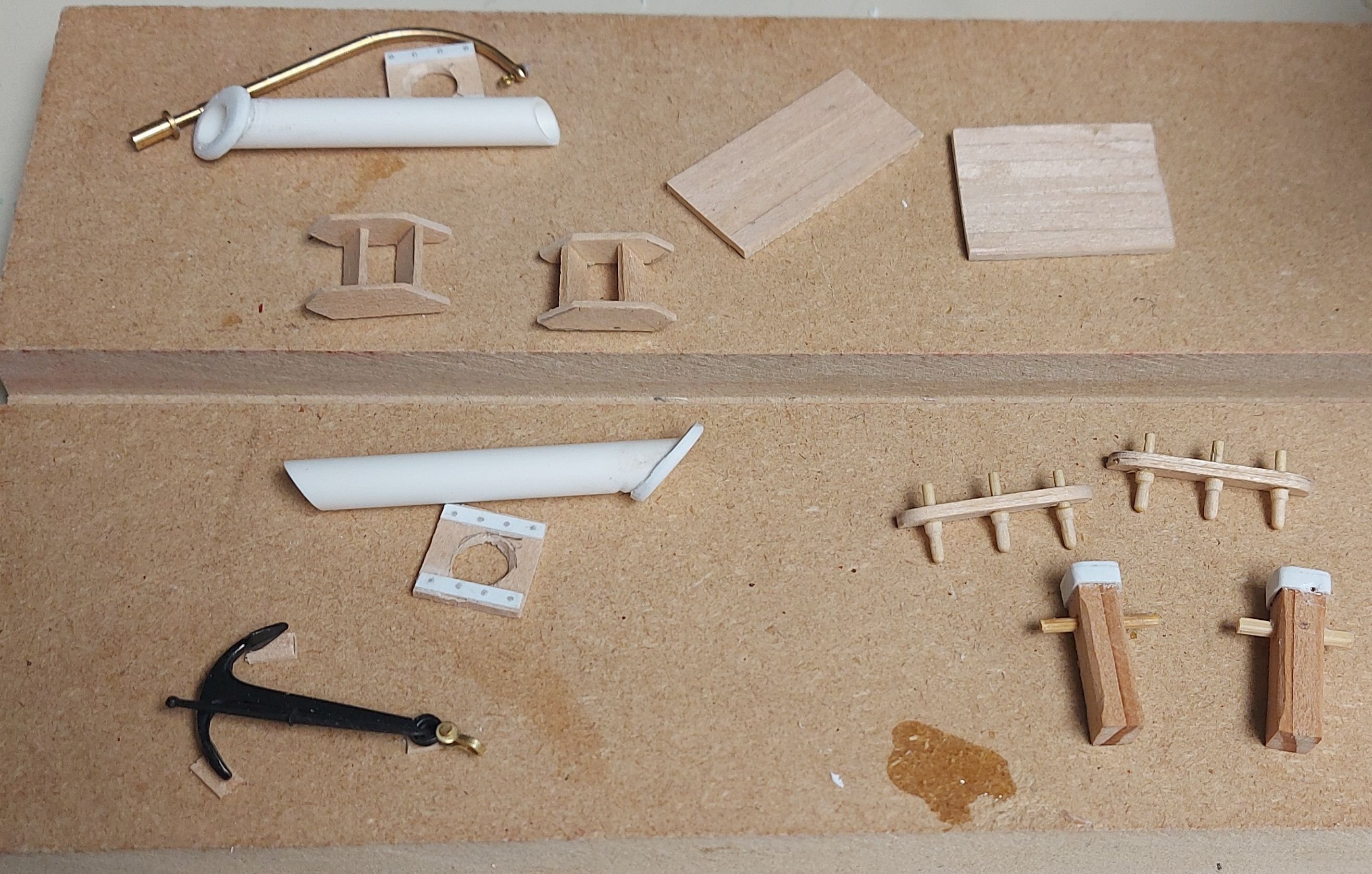
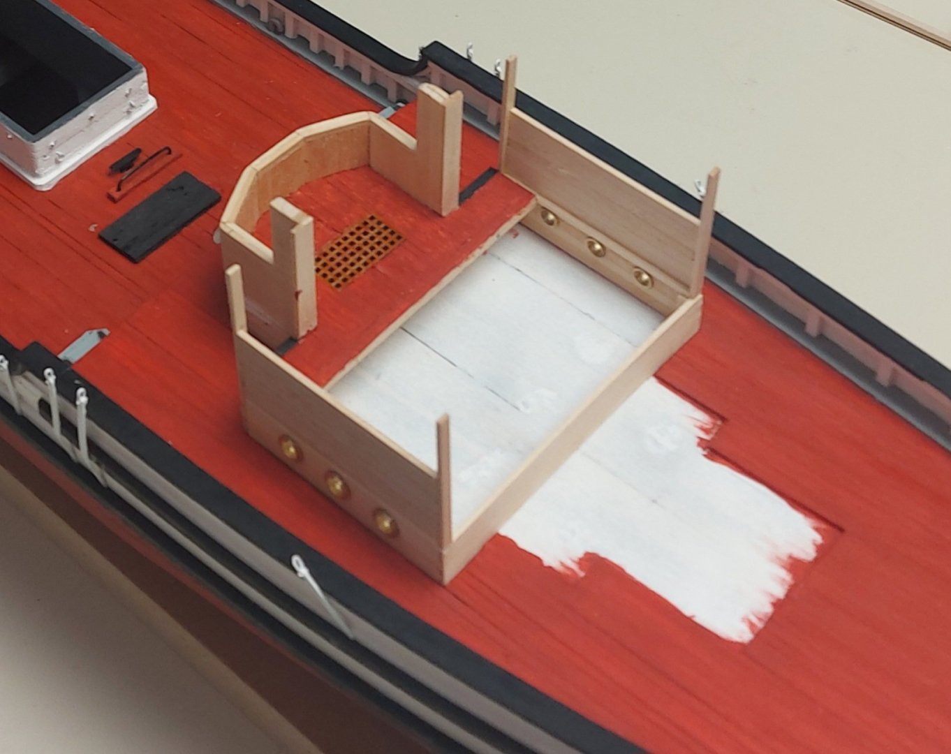
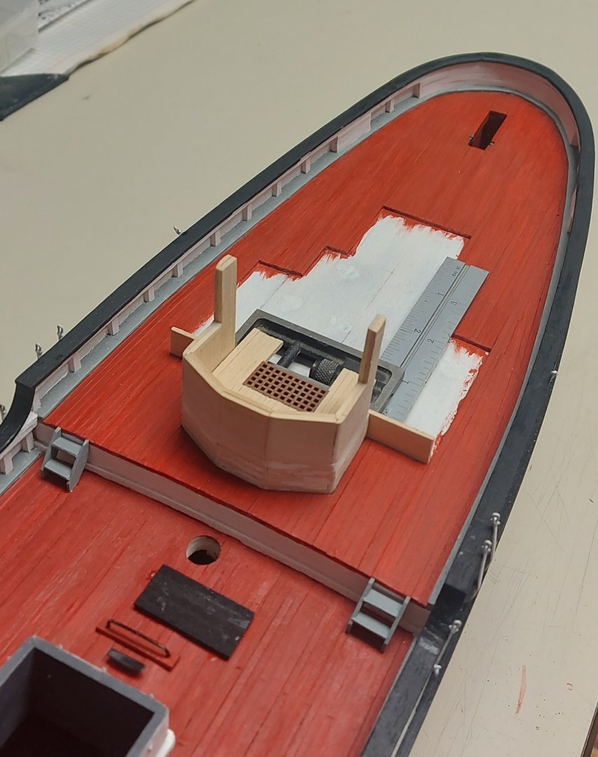
OK, all the fiddly bits are mounted on the main and foc's'le decks, and they are essentially complete. I need to make the hatch cover, fo'c's'le deck hand rails, and the platform on the starboard side that was used for swinging the lead. Besides the large items that are plainly seen, there are 30 'wedge keepers(?)' that hold canvas covers in place, 24 ring bolts, 2 deck lights, 8 gooseneck vents, and 6 fuel and fresh water tank filler caps. The black rectangles are bases for the winches which will take me a while longer to build. The small hatch forward on the main deck is access to the sail room, beside it is the freshwater pump. Everything is scratch built, except the 2 bollard fairleads at the stem, the anchor and its' davit. I find it interesting that the chimney for the Quebec heater extends above the foot of the jib sail, so the crew would have to lift the sail over the chimney when tacking... If I wanted to get ahead of myself I could step the masts, but I will move on and complete the poop deck first!


- 368 replies
-
- 11
-
-
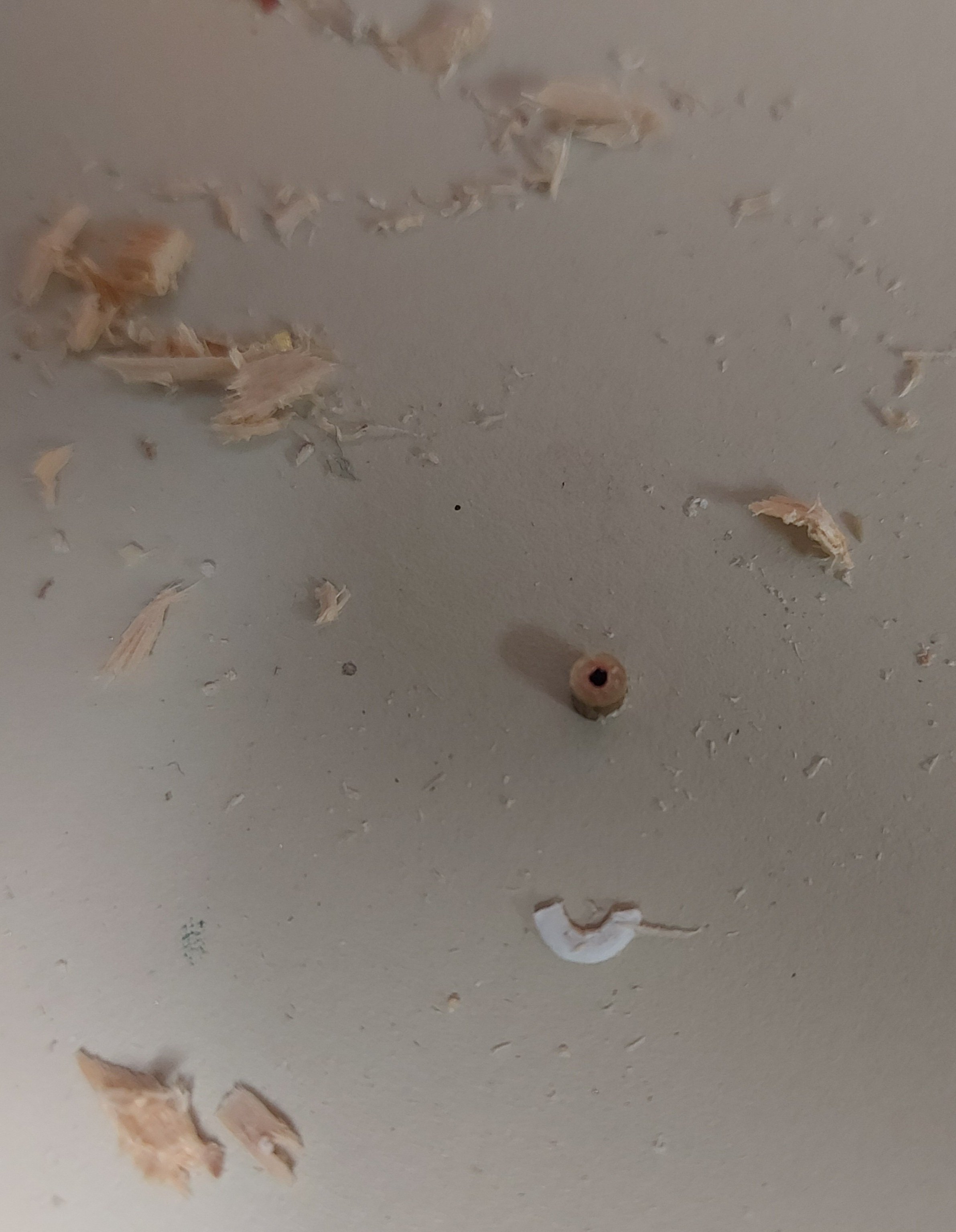
While trying to install the base of my anchor davit it went skittering across the fo'c's'le deck and down the hawse hole to the depths of the interior! I got it back by holding the ship upside down and giving things a good shake. I did get the part back, and I thought I had been keeping the interior pretty clean, but all the dross in the picture fell out, including a missing fuel filler cap! Fun and games!

- 368 replies
-
- 10
-
-

-
Well spotted and quite right, they are getting another spin on the Dremel! Rregards, Bruce
-
Thanks Keith... I bought almost all of the fittings I needed for my HMCS Chicoutimi build from Nick at CMB... most needed modification to be period correct but that was ok. It has been a few years since then and I notice the number of suppliers and selection has gone down, but that is not CMB's fault. Still my go-to supplier! Appreciate your kind comment on drilling the hawse... at least if I mess up wood is easy to fix!! Regards, Bruce
-
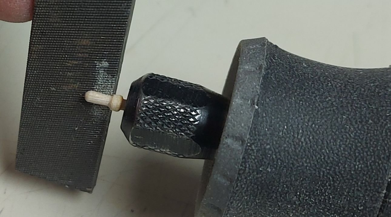
Some fiddly bits waiting for paint... about half way done! I made the belaying pins using my Dremel and a file...

-
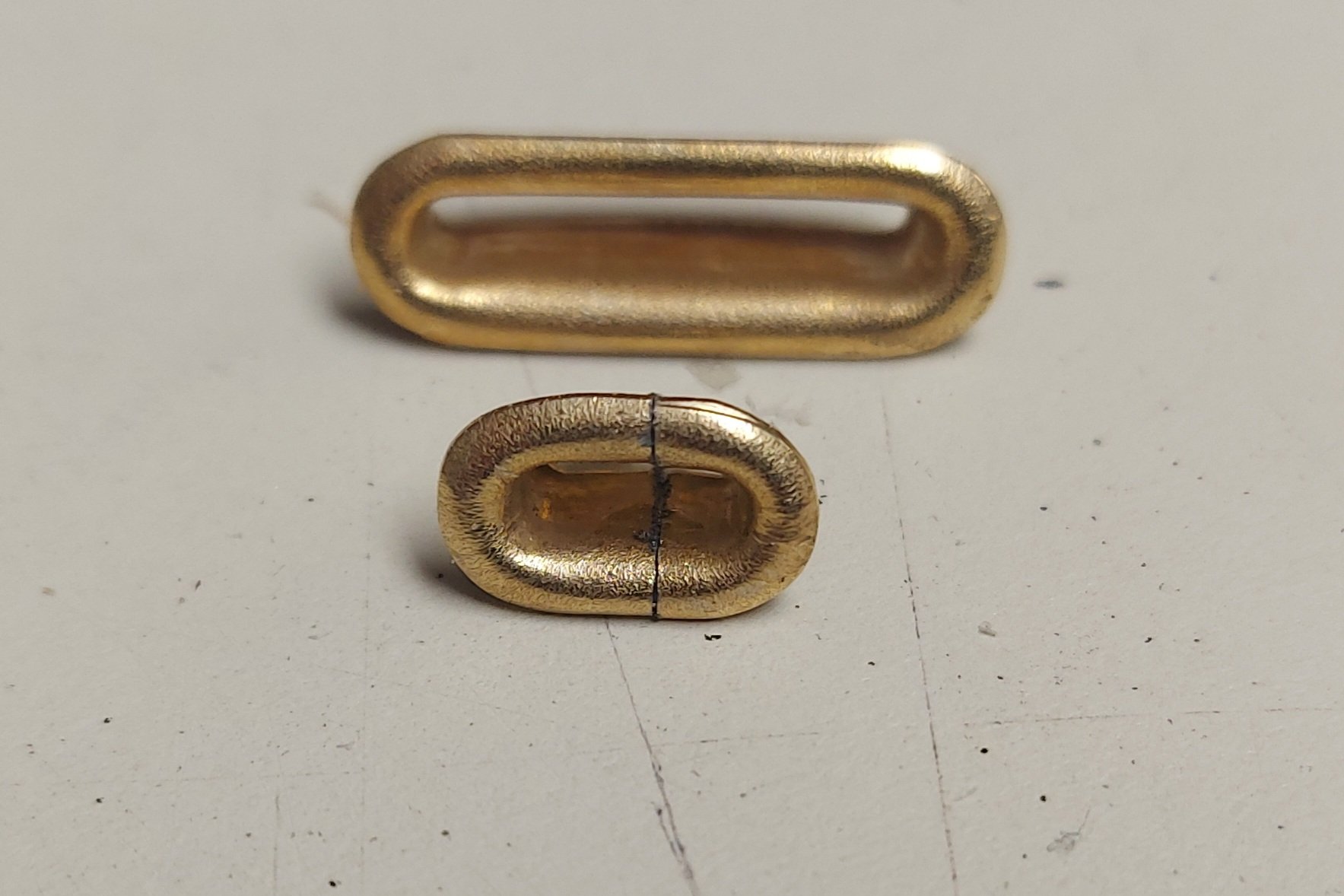
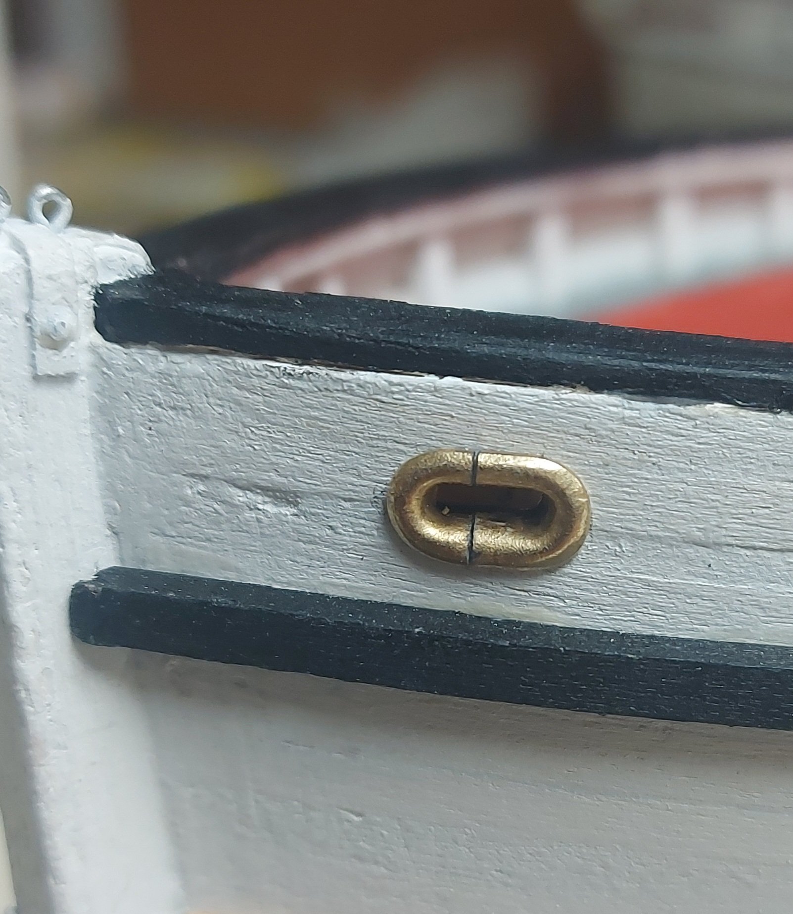
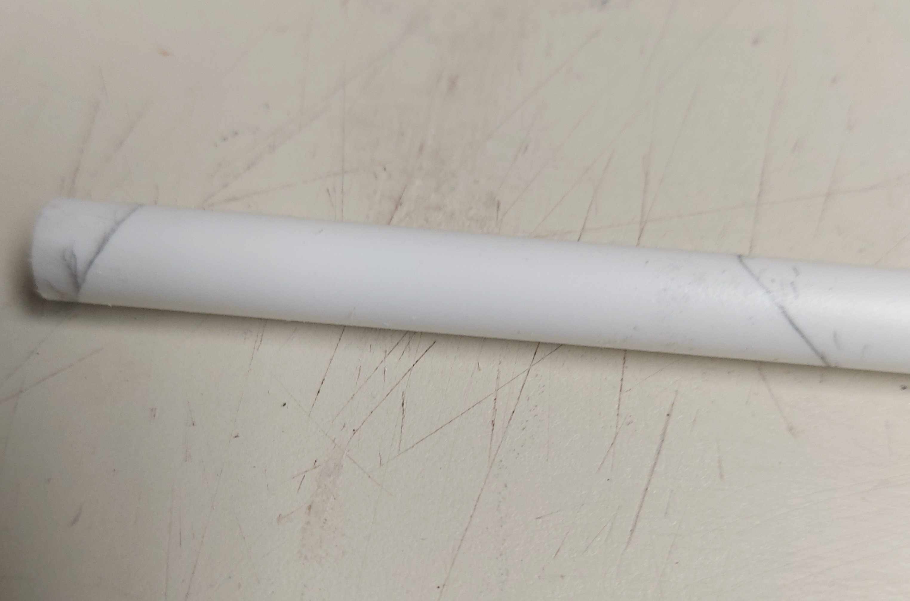
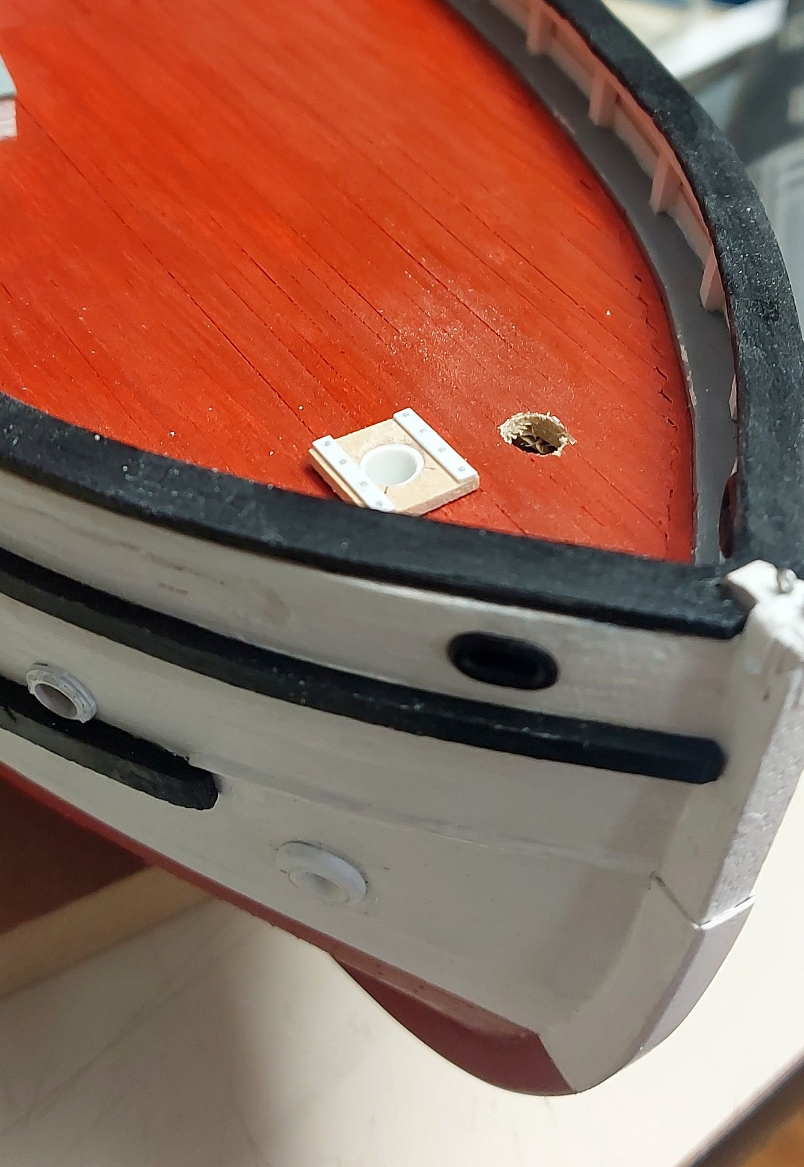
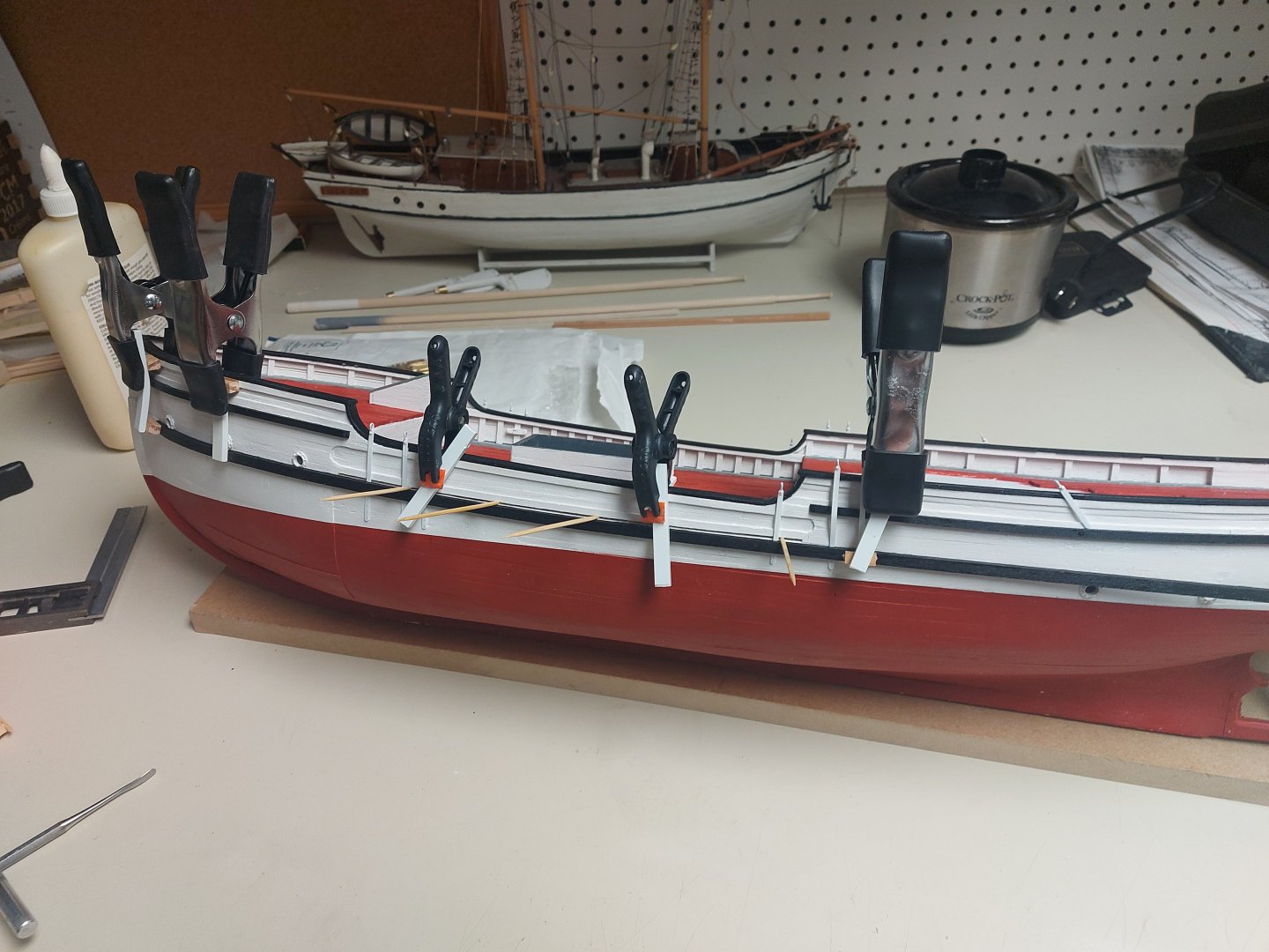
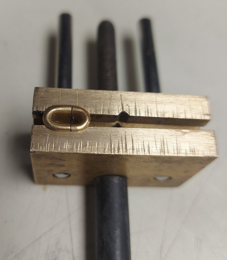
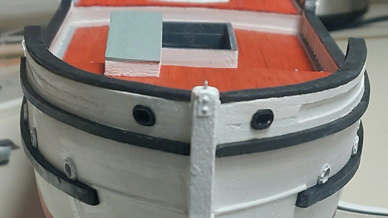
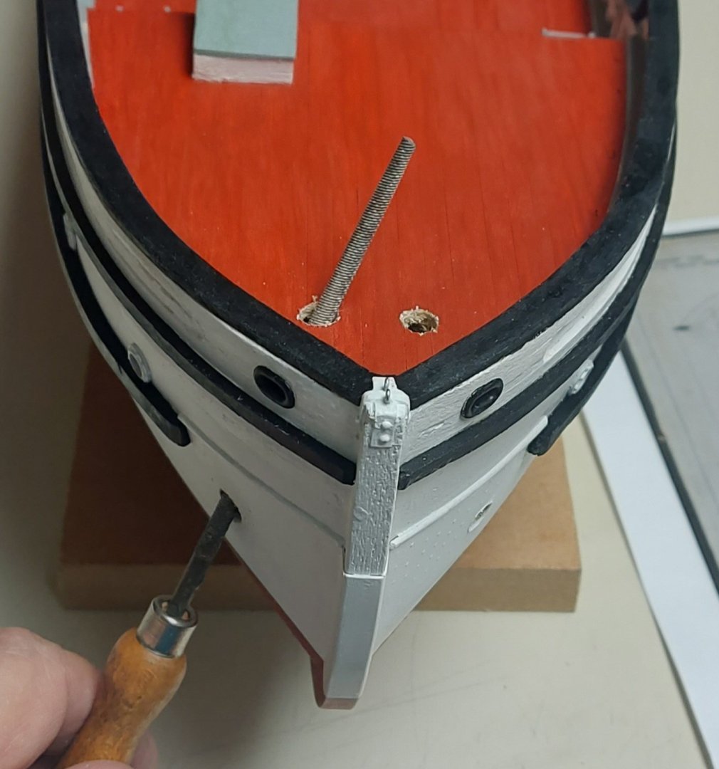
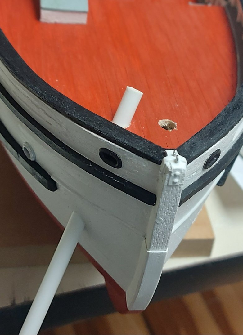
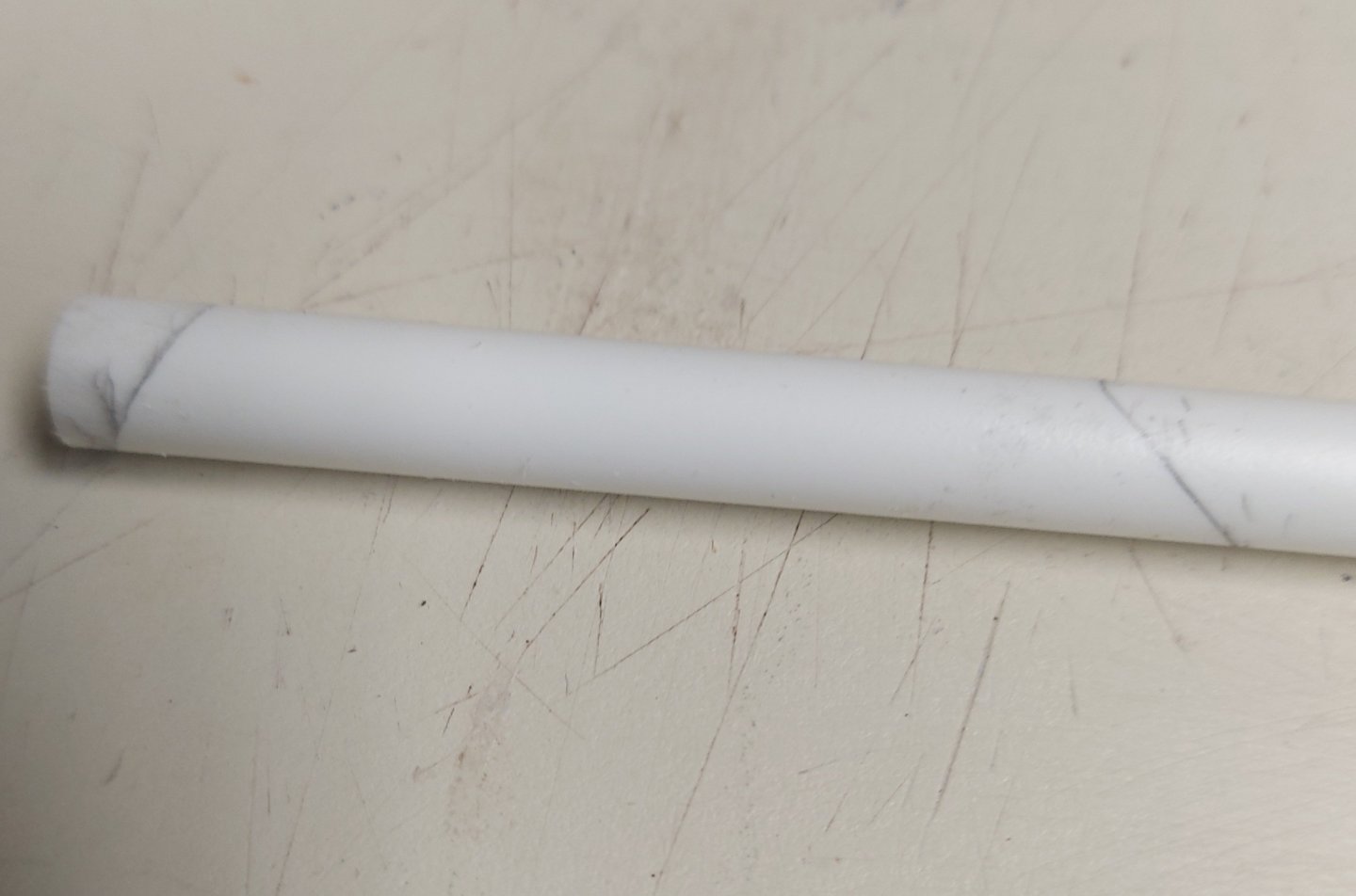
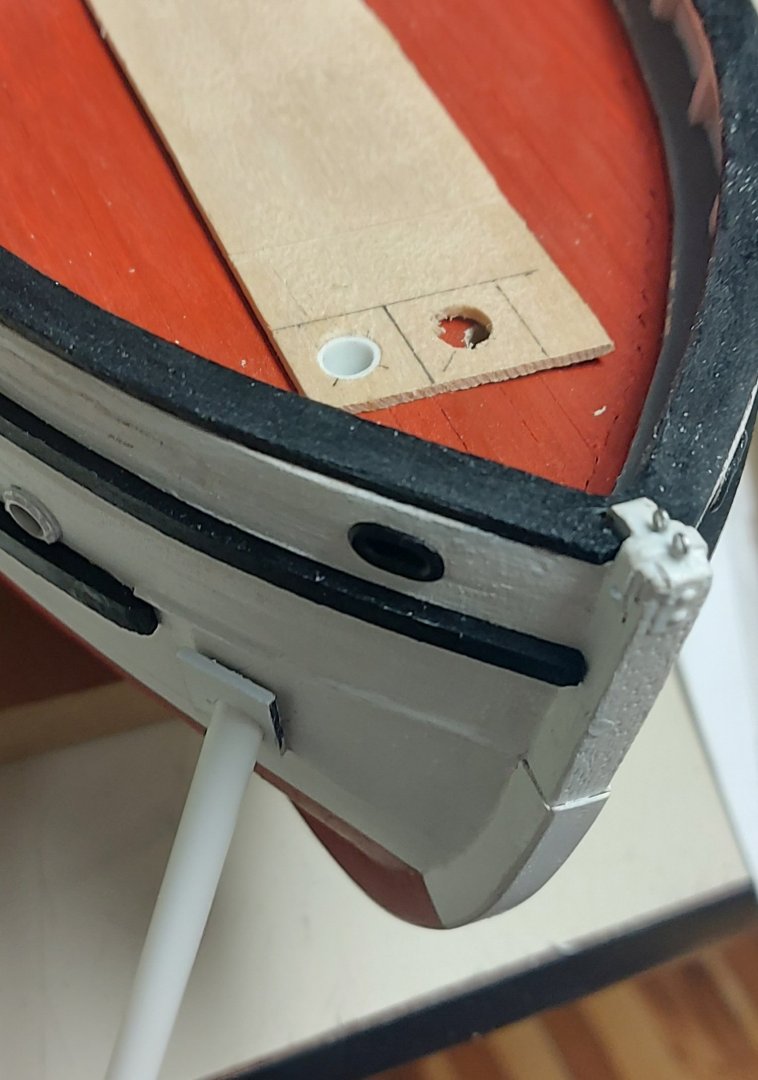
Got the port rub rail on, and started some fiddly bits... There are five fairleads that pass through St. Roch's bulwarks... since the flanges are visible on both sides I ordered 10 from Cornwall Model Boats. They are not the correct size so I used my small hobby vise and Zona saw to cut them down and glue them back together with CA... Here is one being test fit to the bow, again use Forstner or brad point bits for drilling clean holes! And here are the pair installed at the bow... How I proceeded to make the hawse... this should be the last of the hole drilling forward of the poop deck! I measured not twice, but three times, off the plans to locate the ends of each hawse pipe, double checking against photos and the model to ensure they are symmetrical on my hull... After drilling the holes straight into the hull I used my 4" round file to set the hole profile. Then my 1/4" styrene tube was fitted... And the pipe marked for cutting... I roughed in the hawse rubber on the deck, and the flange on the hull, and glued the flange to the pipe... Then I filed and sanded the flange to shape, detailed the rubber, and test fit to the hull... one more to make, then paint and they'll be ready for the anchors! Stay tuned for more fiddly bits! Regards, Bruce


- 368 replies
-
- 20
-