Jay 1
-
Posts
654 -
Joined
-
Last visited
Content Type
Profiles
Forums
Gallery
Events
Everything posted by Jay 1
-
 Thank you so much for your support, condolences, and kind words, Keith, Andrew, and Nirvana. ☺️
- 63 replies
-
- 4
-

-
- Lady Eleanor
- True Vine
- (and 2 more)
-
Thank you, Keith and Andrew for your concern and kindness. I recently had a death in my immediate family. My build and MSW time have taken a backseats with all the things that have needed tending. It’s been a rough patch lately but we’re all doing okay. It’ll be a pleasure to get back to building when things ease up a little more. 😊 Thank you again guys! Jay
- 63 replies
-
- 5
-

-
-
- Lady Eleanor
- True Vine
- (and 2 more)
-
Agree with Eric. The machinery at the aft end along with ballast in the barge would work. Can likely get a rough estimate of the boom & hammer weight by calculating boom & timber dimensions + hammer & misc. & grossing up. I’ve seen modern ones secured either to shore and/or to piles on the sides.
-
You’re welcome, Keith! Sounds good—hope the sawdust works but if not, ya got a fallback fer trying out. 😉
-
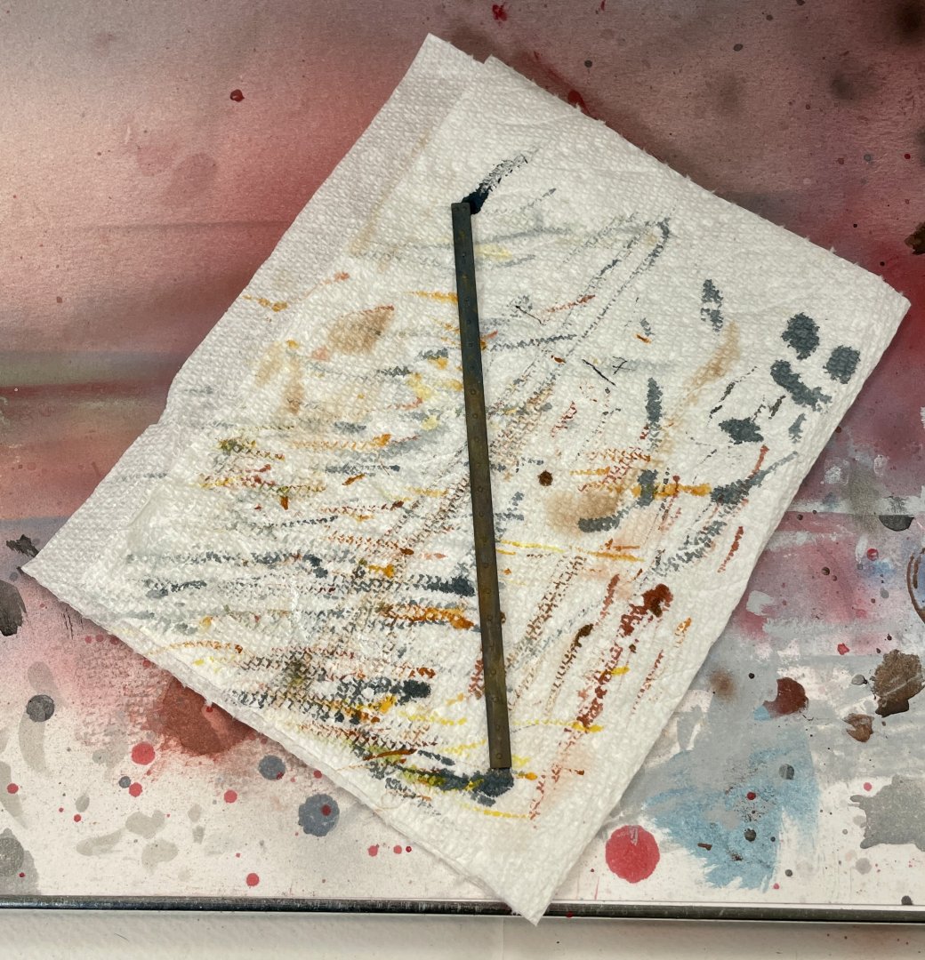
If you would like to try it out to for the algae on your build, Keith, I meant I'll mail you few different packets of colors of stuff like what's in the picture.
.thumb.JPG.c494b429513b64669c7c7e12802871e2.JPG)
-
Didn’t see Eberhard‘s post about Woodland Scenics until just now…speak of the devil, i.e., the foam. I did a trial run with it for my build late yesterday to see how it would work for algae. It looked good so just before I jumped on MSW, I started setting up full-on tests on some styrene sheeting a few minutes ago. Had a laugh at myself when I saw the algae hull picture in your log…I spent about an hour plus last night looking at algae on hulls (Alamy pictures)….🤪🤣 Long story short, Keith the stuff I’m using is really fine and might work for you. If you PM me your address, I’ll pop a few different colors into the mail so you can try them out. Cheers, Jay
-
Oh wow, I totally missed the start of your latest build, Keith! I just finished your log and it’s a great subject and your work is fantastic! I’m looking forward to seeing how you tackle the weathering. Spot on about finding the balance between the scale and not getting carried away. You’ll hit it out of the park my friend!
- 63 replies
-
- 2
-

-
-
- Lady Eleanor
- True Vine
- (and 2 more)
-
My apologies for not thanking everyone for looking in, your likes, and for your kind words earlier this week! Shortly after posting my last updates, I had a couple of high-priority, short deadline things assigned to me at work. Can't complain about that too much, as my work makes so many things possible for me. 😉 Spot on about Marsh, Andrew--he's a goldmine of information that without his work, we likely wouldn't have. I recently picked up a copy of his Sailing Trawlers for my future Erycina build that's down the road (she's waiting patiently for some attention on my shelf). Being able to add all sorts of details and etc. are one of the reasons why I enjoy building these little guys so much--they leave a lot of room for expression. Keith, you've had some great adventures that sound very cool (I hope they were or they are now in retrospect)! Good point, and well taken, on how skippers can let things slide as they age. Yep, my statement was a bit too absolutist.... 😝 🤣 I love looking in on Gary's work--he's a superb craftsman/artist! Where I really was coming from is I've seen weathering that's been so overdone that it doesn't look natural/believable or it doesn't fit in with the rest of the model's setting, if that makes sense? Gary's weathering is beautifully done on his models and fit/belong within the settings he creates. Maybe what I'm trying to say, but maybe not so well, is the effect I'm after is something that looks believable vs. something that looks over-the-top? Again, thank you all for popping in, for your likes, for your kind words and encouragement, and for keeping me on my toes! Hope you all are having a great weekend! Jay
- 63 replies
-
- 2
-
-
- Lady Eleanor
- True Vine
- (and 2 more)
-
Andrew, she's a cracking build--I really enjoy your excellent craftsmanship! Cheers, Jay
-
Hull Construction – Weathering Some of my next steps will be weathering the hull. Given that the hull paint job turned out really well, weathering the hull was a decision I went back and forth on for a day or two. The deciding factors to weather were this was an original intent at the start of my build and that I want to tell a small story with the build which the weathering will help accomplish. Also I have a couple more upcoming fishing builds, so I may do one of those with a pristine paint job…we’ll see. With weathering, I feel that less is often more. I won’t do heavy weathering to the build—it would not make sense in the context of these boats. People’s livelihoods depended on these boats and were also significant financial investments (see background to get an idea of their cost). With those factors in mind, a skipper would not likely let his boat become beat to hell; likewise, if members of the crew were also partial owners as well, they too would likely not let their investment get beaten into the ground due to neglect. Crew that weren’t partial owners also likely wouldn’t crew on a badly neglected boat because that would have put their lives at even greater risk (see background for more about loss of life on these boats). On the flipside, it’s highly likely that general maintenance and upkeep would take a backseat during fishing season(s). The boats generally worked 6 days a week during fishing season, and since many of the skippers and crew were devout, they did not work on Sundays. These latter aspects are where I’m setting my intention for weathering my build. I want to depict a boat that’s been working hard during a herring season. In other words, I’m not going to depict a boat that’s been beat to hell but also not one that looks like it just rolled off its shipyard stocks. Over the next week or two, I likely won’t post build updates. During this time, I plan to play around off build with weathering to see if I can hopefully come up with what I want and can translate to the actual build. I think what I have in my mind’s eye will look pretty cool on the boat…stay tuned! Cheers, Jay
- 63 replies
-
- 6
-
-
- Lady Eleanor
- True Vine
- (and 2 more)
-
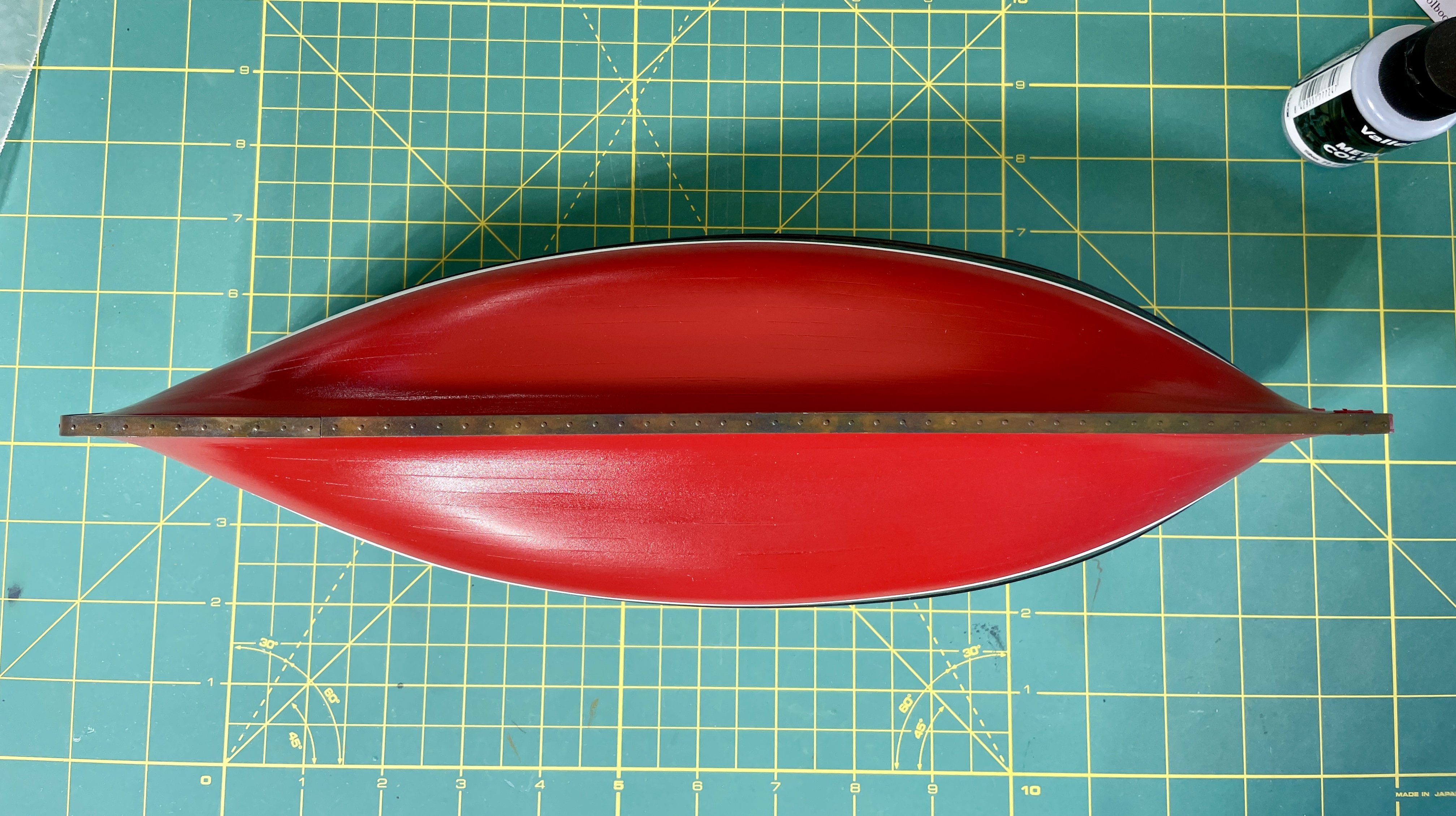
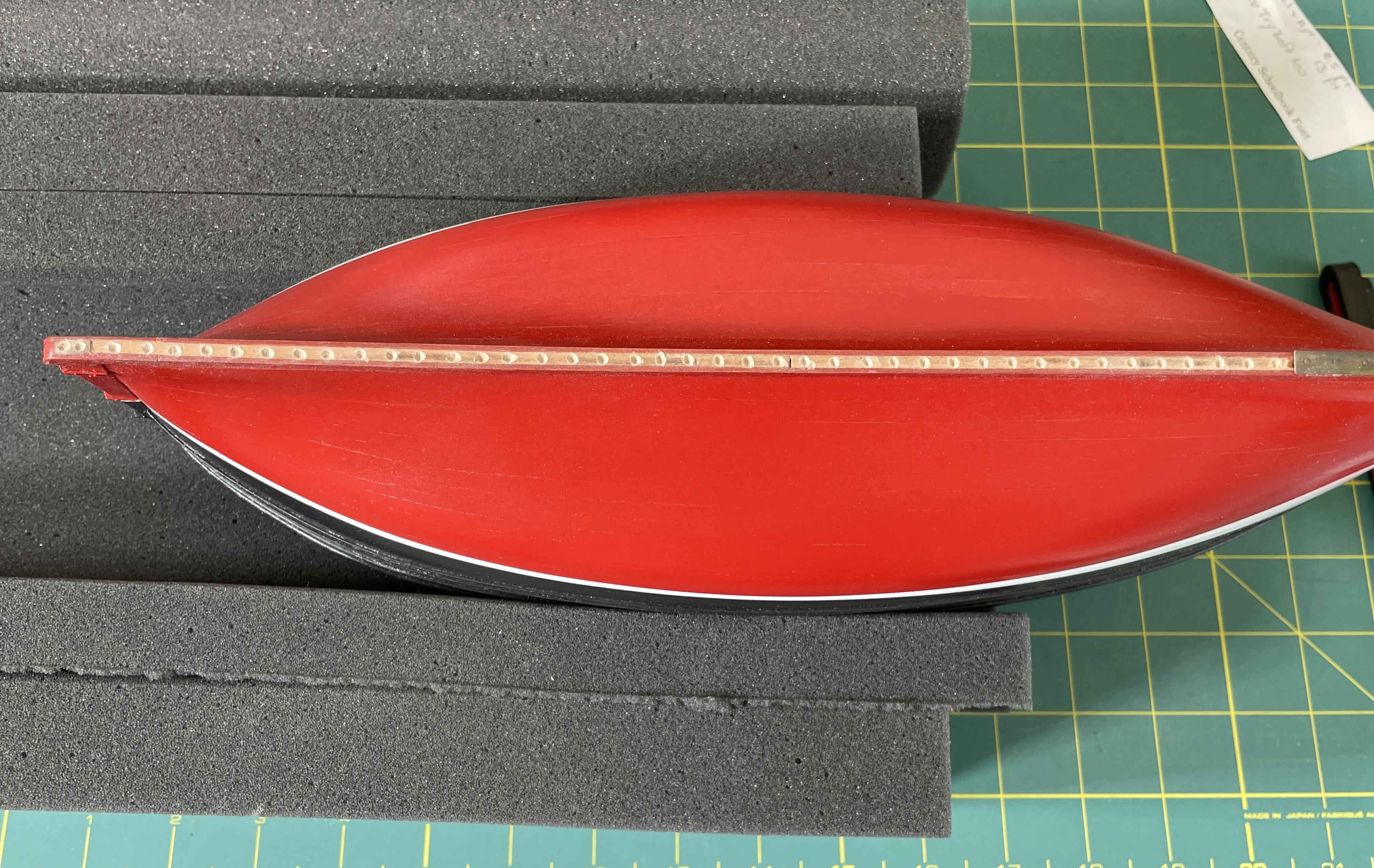
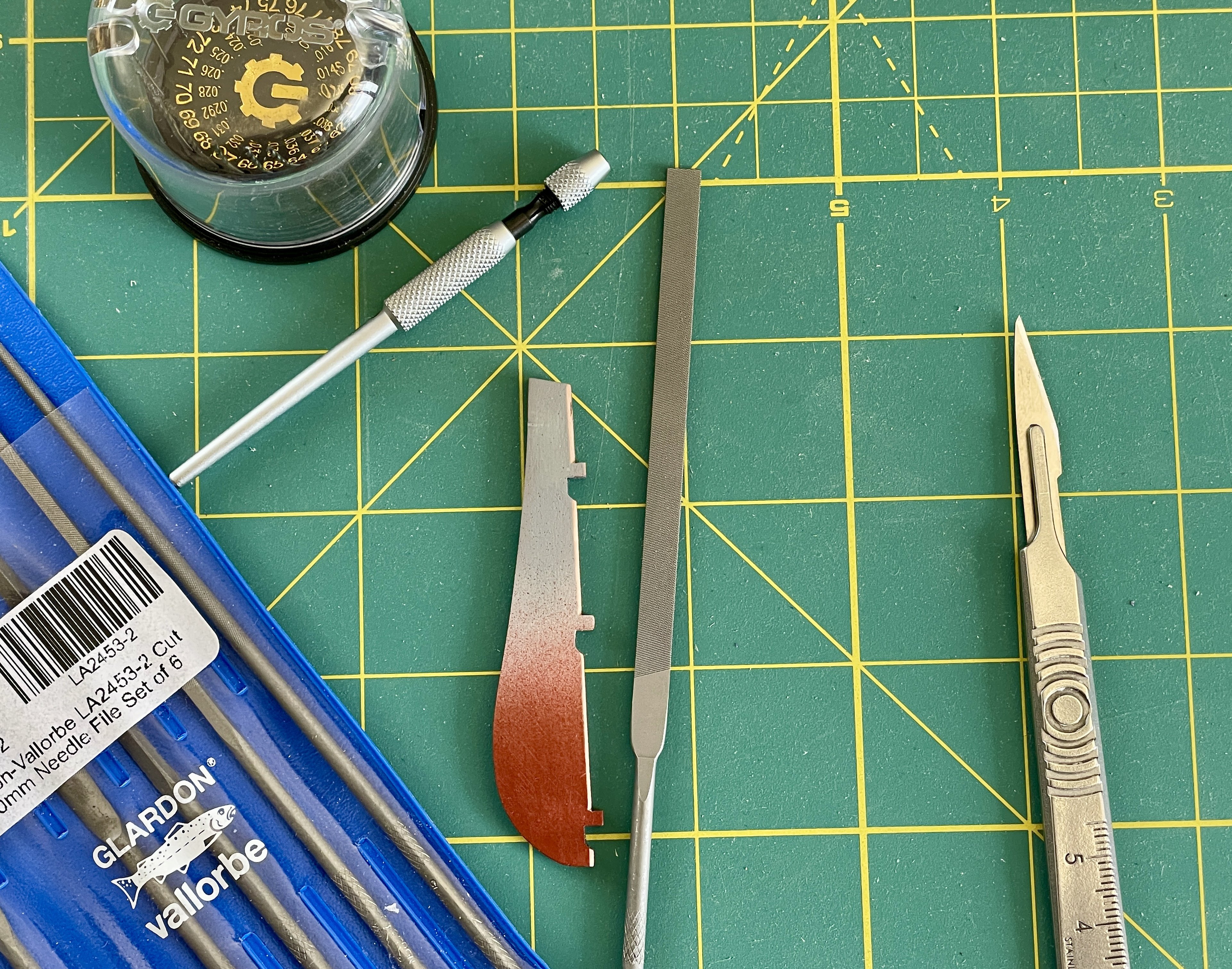
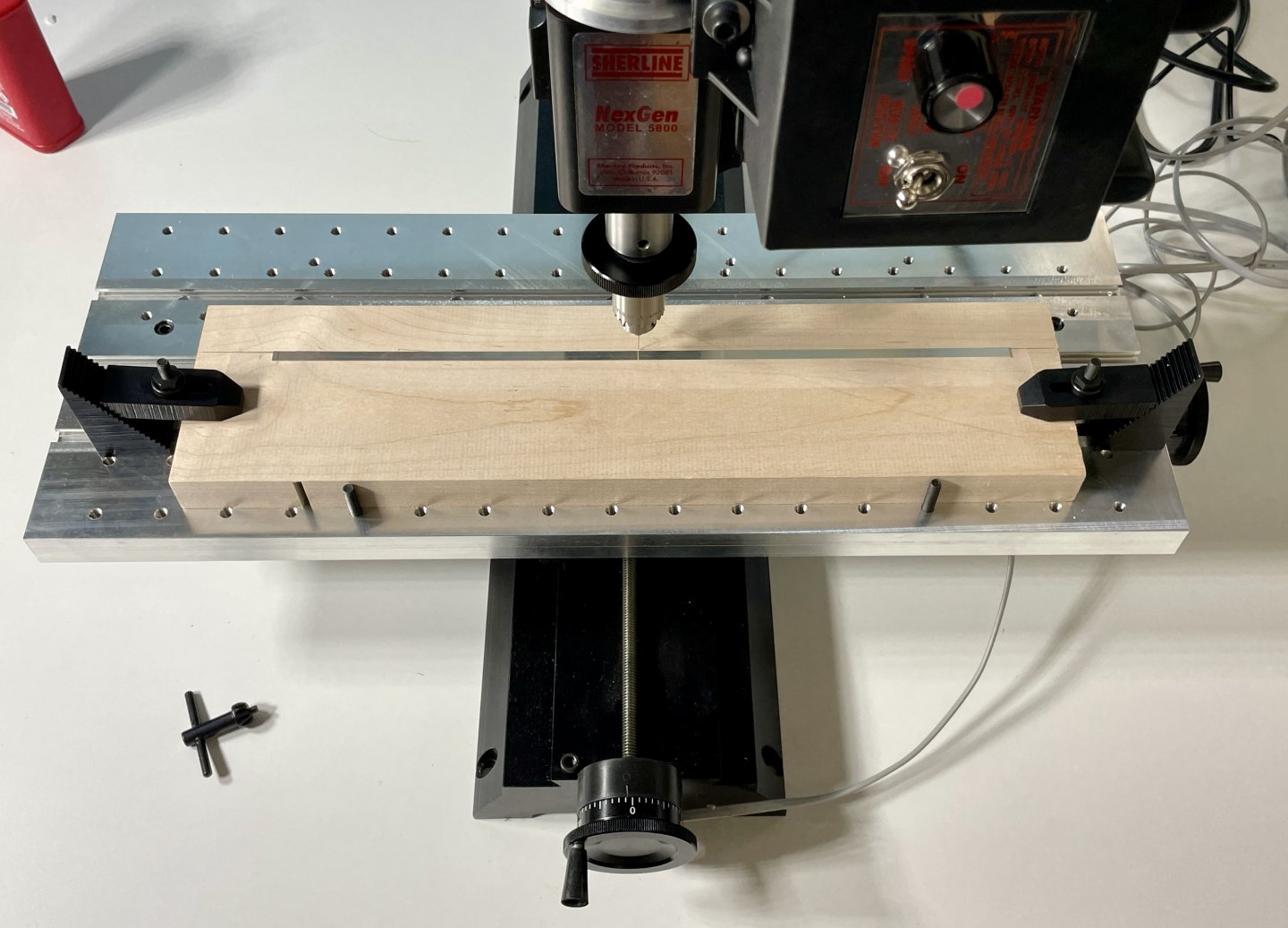
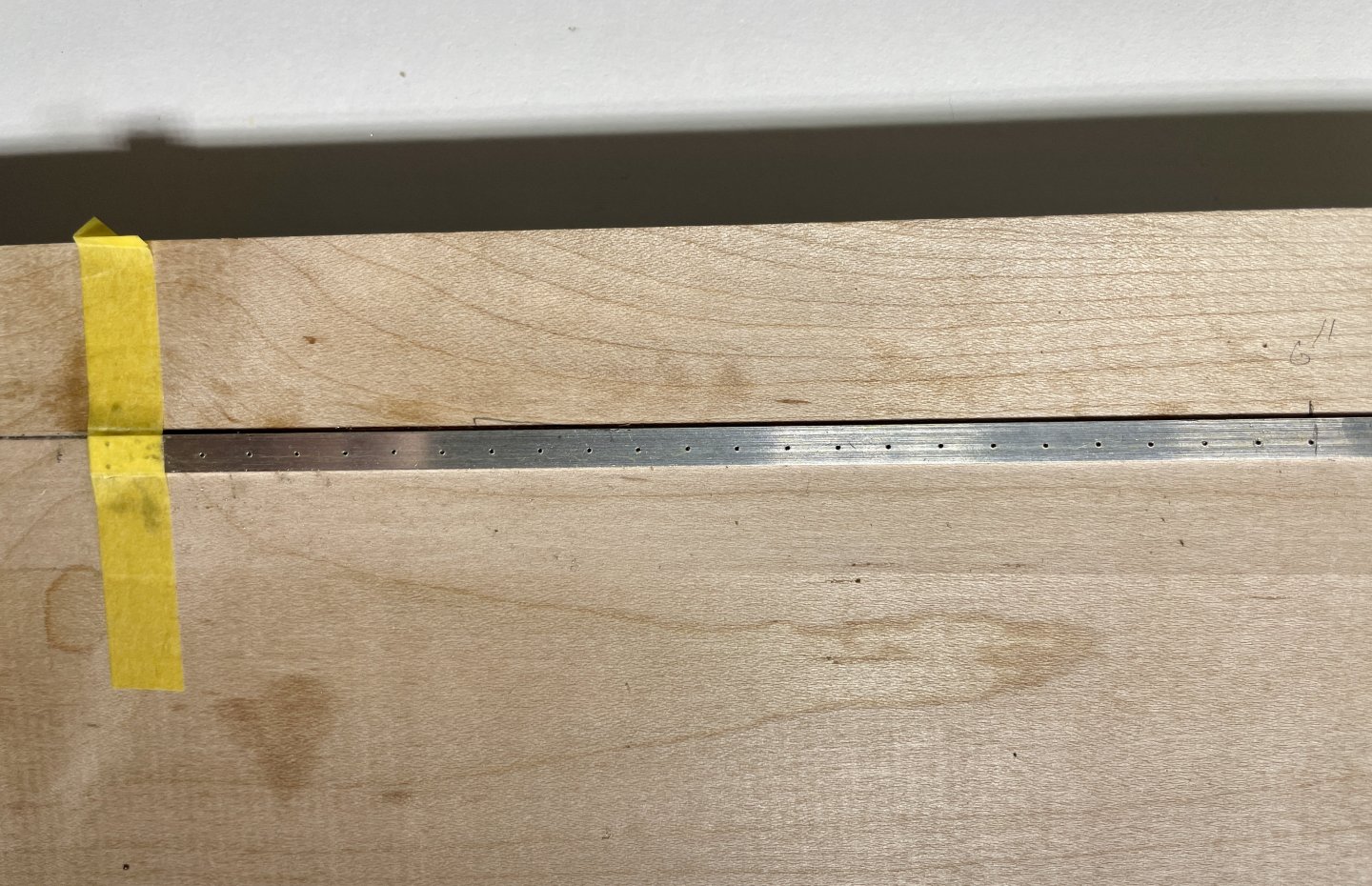
Hull Construction – Stem and Keel Plates The Vine had 7/8” (22mm) plating both on her stem and keel. The keel plating may have been installed after the Vine’s back was broken but that’s speculative. Also I’m unsure if the stem and keel plating was iron or steel but it likely was steel because by 1905, the price for steel was quite reasonable and Scotland was a major steel producer. I could not source 5mm brass for the 5mm wide stem and with not having a mini table saw, hand cutting brass strips with a reasonable gauge (ga) didn’t work. Where I hit the jackpot for finding 5mm material was a jewelry website site that I periodically order stuff from. They stocked 24 ga, 5mm wide sterling silver strips for making ring bezels. While the sterling silver was considerably more expensive than brass, the cost wasn’t prohibitive and it turned out to be a better material to use on the stem because sterling is much more malleable than brass. Thus making the stem-to-keel bend was considerably easier than if I had used brass stock. Making the plates for the build was fiddliness on steroids! I used my mill to drill more than 65 nail holes with a #76 (0.020” / 0.5mm) drill. I then pickled the brass nails I used so they would better take paint. I cut all the nails to about 2mm lengths, inserted then into the drilled holes, glued them in with superglue, and then flush-cut each nail. Installing the nails took hours because of their size and their domed heads. The domed heads made it difficult to firmly hold the nails with tweezers…quite a few wound up getting launched into the wild blue yonder! The reason I went this route with the nails was because I needed to paint the silver I used. It would have been incredibly difficult to paint and then clear coat each plate installed on the hull. Because the nails slightly protruded beyond the silver’s ga after I flush cut them, I needed to make 65+ indentations in the stem and keel. For this I used a burr which I ran between 5 and 6 K rpms. I needed to go slow to help prevent the burr from skating off the stem/keel and damaging the twice now painted hull. I then primed, painted, weathered, clear coated, and superglued each plate to the hull. It took a several strip and re-dos on each plate’s weathering until I was happy with how they looked. A list of the paints I used on the plates is below the photos. The photos that follow capture some of the process described above. Paints: MRP MRP-LPG, Pro Acryl MPA-056, Vallejo 77.712, and Ammo Atom 20054, 20047, 20045, and 20023. Cheers, Jay


- 63 replies
-
- 7
-
-

-
- Lady Eleanor
- True Vine
- (and 2 more)
-
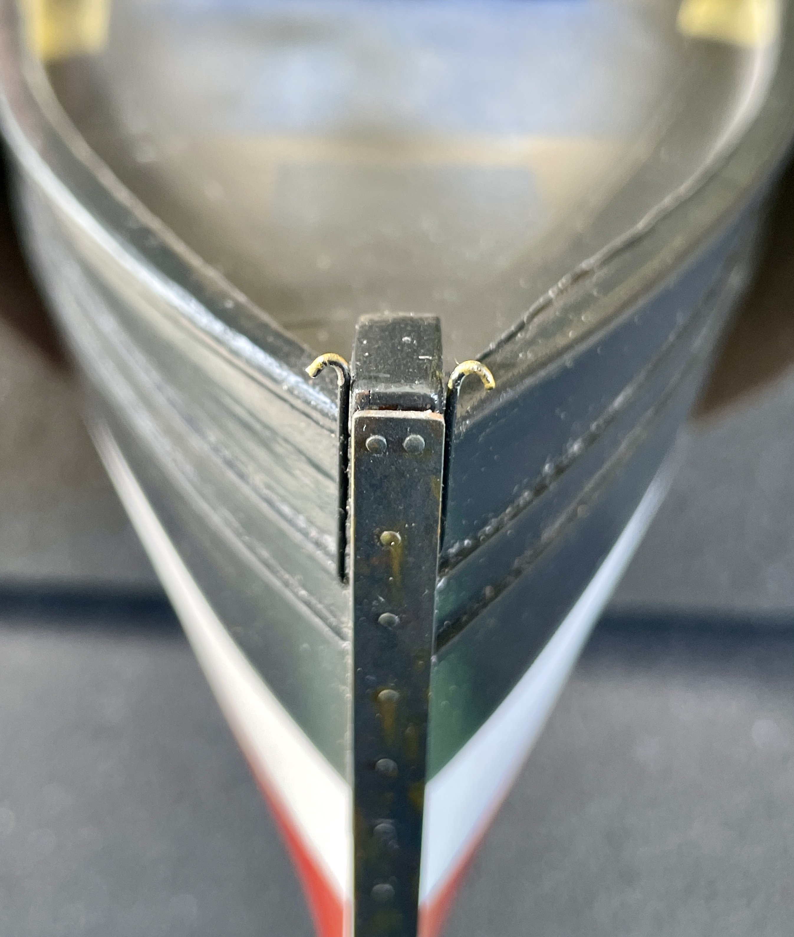
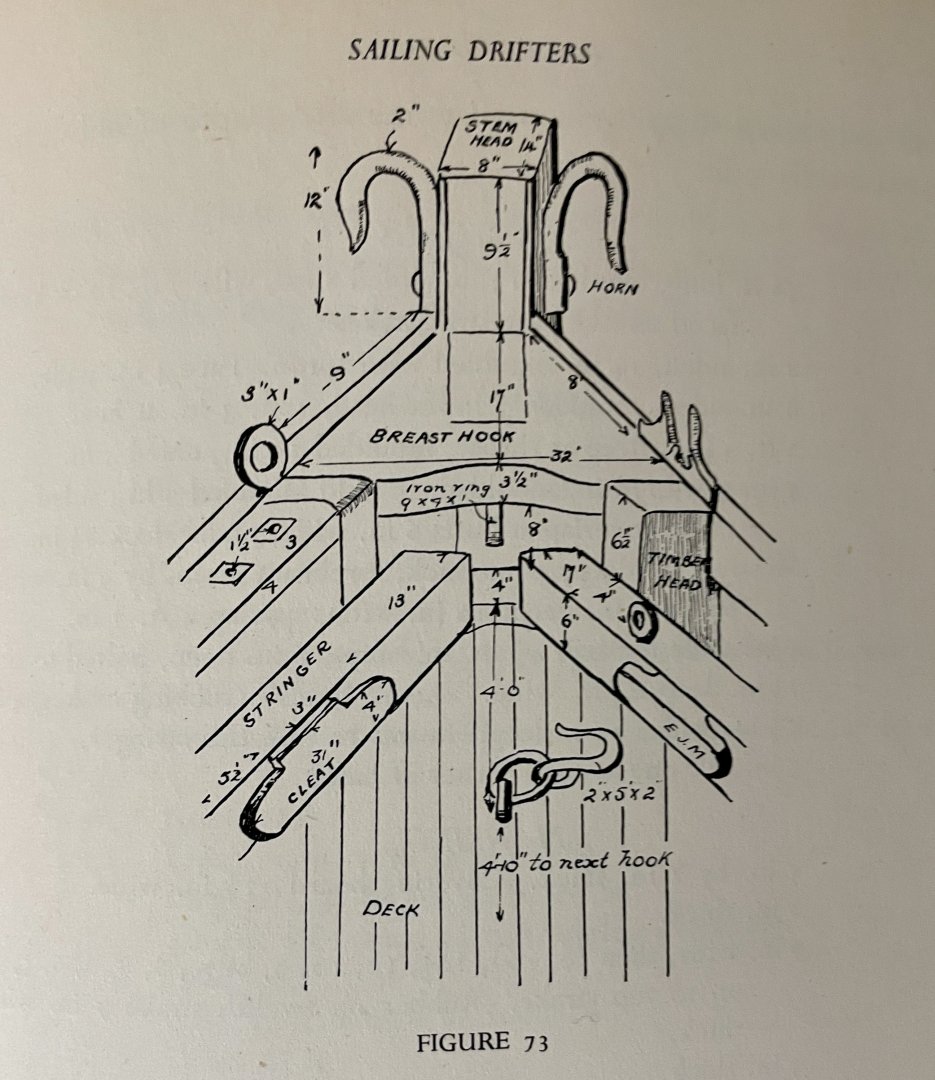
Hull Construction – Stem Horns Rather than secure the mainsail’s tack to the top of the stem per the kit, I followed Oke and Marsh’s Vine plans and added horns to the stem for that purpose. From Marsh’s Sailing Drifters, fig. 73, p. 281, it appears horns were predominately used on both Fifies and Zulus. According to Marsh, the Vine’s horns were “1 ft. by 7 in. by 1¾ in. [~ 305mm x 178mm x 45mm],” (Marsh, 271); however, his 7 inch (178mm) dimension does not make sense! At scale, the lengths of each horn would be about 5mm. Making horns at that length wasn’t a problem; however, where I did encounter problems with 5mm horns was attaching them to the stem. Making 90° degree bends at 5mm left gaps between the wire and stem that were too noticeable. Soldering stubs at 90° degree to the 5mm lengths also didn’t work because the butt joints were too fragile and always broke off after cleaning up the solder joints. And lastly, with the horns opposite each other on the stem, which is 5mm thick, each stub length had to be about 2mm. A 2mm stub length was too short for securely fastening the tack to a horn—i.e., a horn would pull out of the stem. The final solution I came up with for the horns was to make their lengths way over scale, give them sharp 90° degree bends, and then offset each horn’s stem attachment point. With the horns blackened and the hull’s black topsides, their lengths and offsets are barely visible. I annealed 0.025’ (0.6mm) piano wire (aka spring steel) to make each horn. Annealed piano wire is easier bend but still retains a lot of strength compared to brass wire. My rationale for using piano wire was I didn’t want a horn to deform when it came time to rig the build. I used Vallejo 77.724 and MIG Atom 20045 for the wear marks and rust on each horn. Overall, making and installing the horns was incredibly fiddly but worth it because I think they add a lot of visual interest to the model at the stem. Cheers, Jay

- 63 replies
-
- 6
-
-
- Lady Eleanor
- True Vine
- (and 2 more)
-
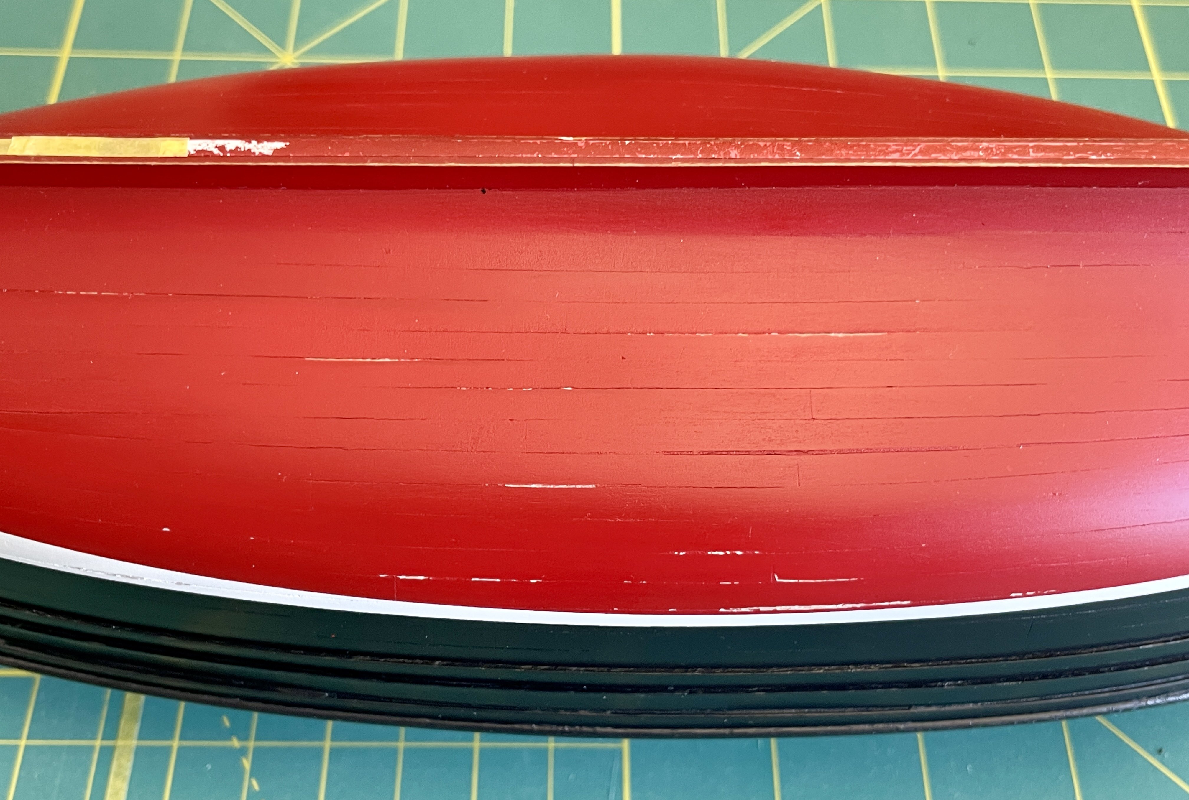
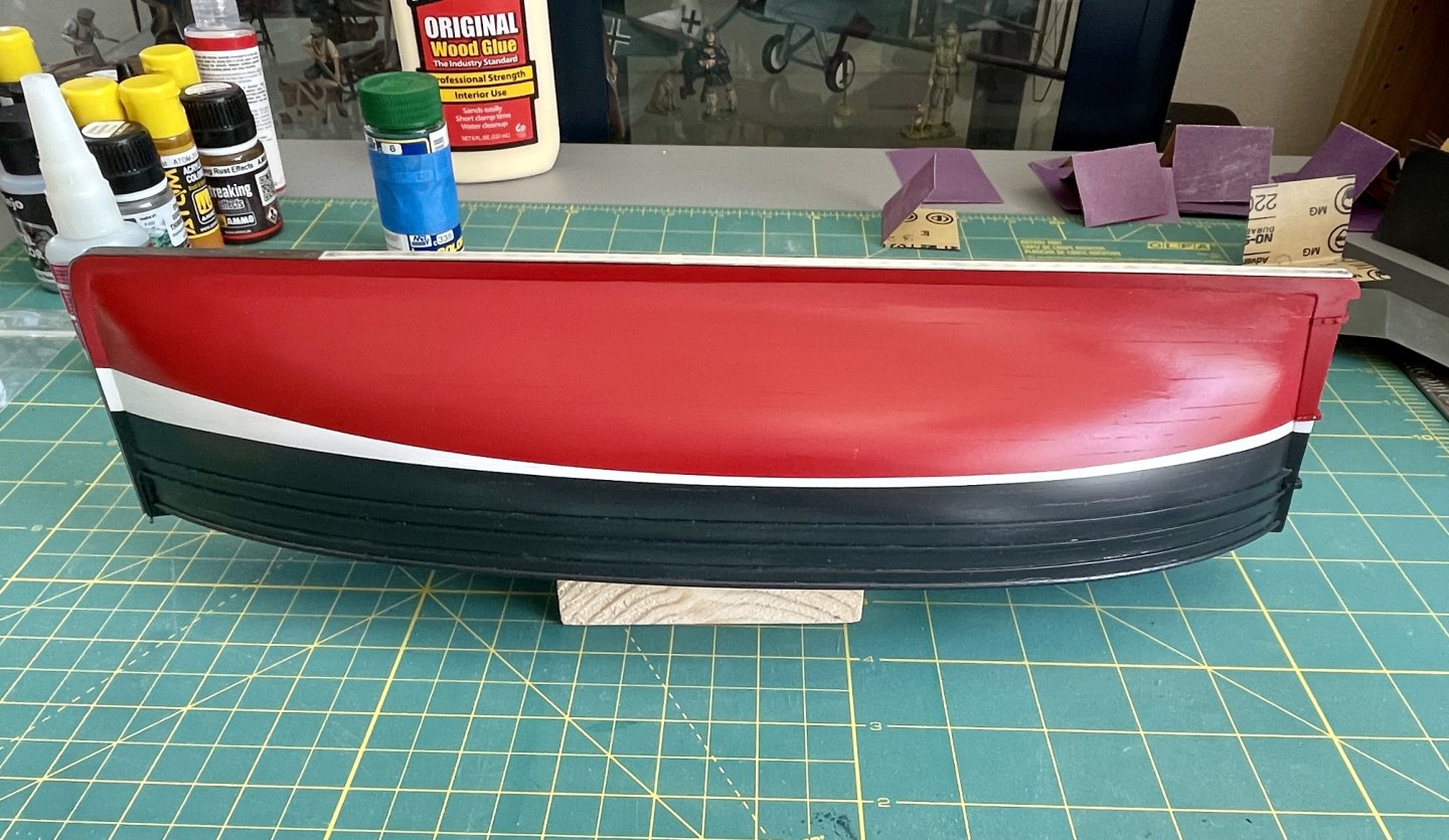
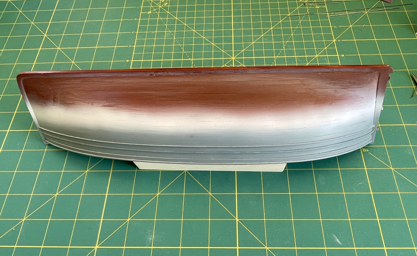
Hull Construction – Paint Repair In my last update, I briefly discussed how a clear coat I applied to the hull had peeled, which was unbeknownst to me until it happened, is an issue with that Ammo gloss acrylic. Using a dilute solution of ammonia was the best option for removing the bad clear coat while also minimizing possible damage to the underlying paint layer. Although the ammonia stripped the peeling clear coat, it also somewhat damaged the hull’s underlying paint—1st photo below—so last week I needed to repaint the entire hull. After repainting the hull, I then airbrushed it with several coats of decanted Mr. Super Clear gloss. The purpose for using gloss is that it provides a stronger, more durable, protective coat than other clear coat sheens. Also I need to use a gloss on the bottom sides for the hull’s weathering. The 2nd photo below is the results of the repaint and gloss clear coats. Cheers, Jay

- 63 replies
-
- 6
-
-
-
- Lady Eleanor
- True Vine
- (and 2 more)
-
Semper Fi, Keith! Thank you for your service: Vietnam. LOL about 29 Stumps—spent a lot (too much) time there. Beirut, Desert Storm, Afghanistan, and Iraq. Regardless of when or where, the bond we Marines share always amazes me—your last post made my day!
- 63 replies
-
- 1
-
-
- Lady Eleanor
- True Vine
- (and 2 more)
-
Thank you, Keith! I’m a retired Marine, so a few choice expletives flew when I saw what had happened. On the bright side, I’m glad I caught it when I did. I’m planning on weathering the hull, so the varnish coat I put on at this stage needs to be decent. Keith, I always appreciate your popping in and your encouragement! Cheers, Jay
- 63 replies
-
- 2
-
-
- Lady Eleanor
- True Vine
- (and 2 more)
-
Thanks, Chuck—the new ones are really nice am a happy builder here!
-
Small Build Update It’s been awhile since I’ve posted an update. Much of my work on the build has been off boat the past couple of weeks. In so far as the build goes, lately it’s been 2 steps forward and then 2 steps back. Although I wanted to post pics and etc. today, that didn’t work out as planned. Earlier today I sprayed the hull with a couple coats of satin varnish that turned into a minor train wreck. I learned ex post facto today that the varnish brand I used has a tendency to peel. Yep, it sure did peel. 🤬 Wound up stripping off the bad varnish and now need to do a major touch up on the entire hull. On the plus side, I was relieved that the underlying paint didn’t get totally destroyed but it did take some damage. After that fun, I decided it was a good time to set the model down and walk away for a break. While the varnish episode totally sucked, I did make some small progress on a few bits and bobs these past couple of weeks that I still can’t install until after I fix the hull’s paint. Hopefully I’ll have some progress pictures to post next weekend. Cheers, Jay
- 63 replies
-
- 3
-
-
- Lady Eleanor
- True Vine
- (and 2 more)
-
Chuck, will you also continue making and selling your wooden boxwood blocks? Thanks, Jay
-
Congratulations, she’s a beauty—well done! Cheers, Jay
- 562 replies
-
- 2
-
-
-
- vanguard models
- alert
- (and 2 more)
-
Chuck, I just received my order that included some of your new 3-D printed blocks and they look fantastic! Am posting here so others know how good these look! Cheers, Jay
-
Nice work on fitting the rub rails—she looks great! Cheers, Jay
- 65 replies
-
- 3
-
-
-
- Maine Peapod
- Midwest Products
- (and 1 more)
-
Thank you AJ, Bob, and Keith for your kind words—much appreciated! Likewise, thank you everyone for the likes and following along! Cheers, Jay
- 63 replies
-
- 4
-
-
- Lady Eleanor
- True Vine
- (and 2 more)
-
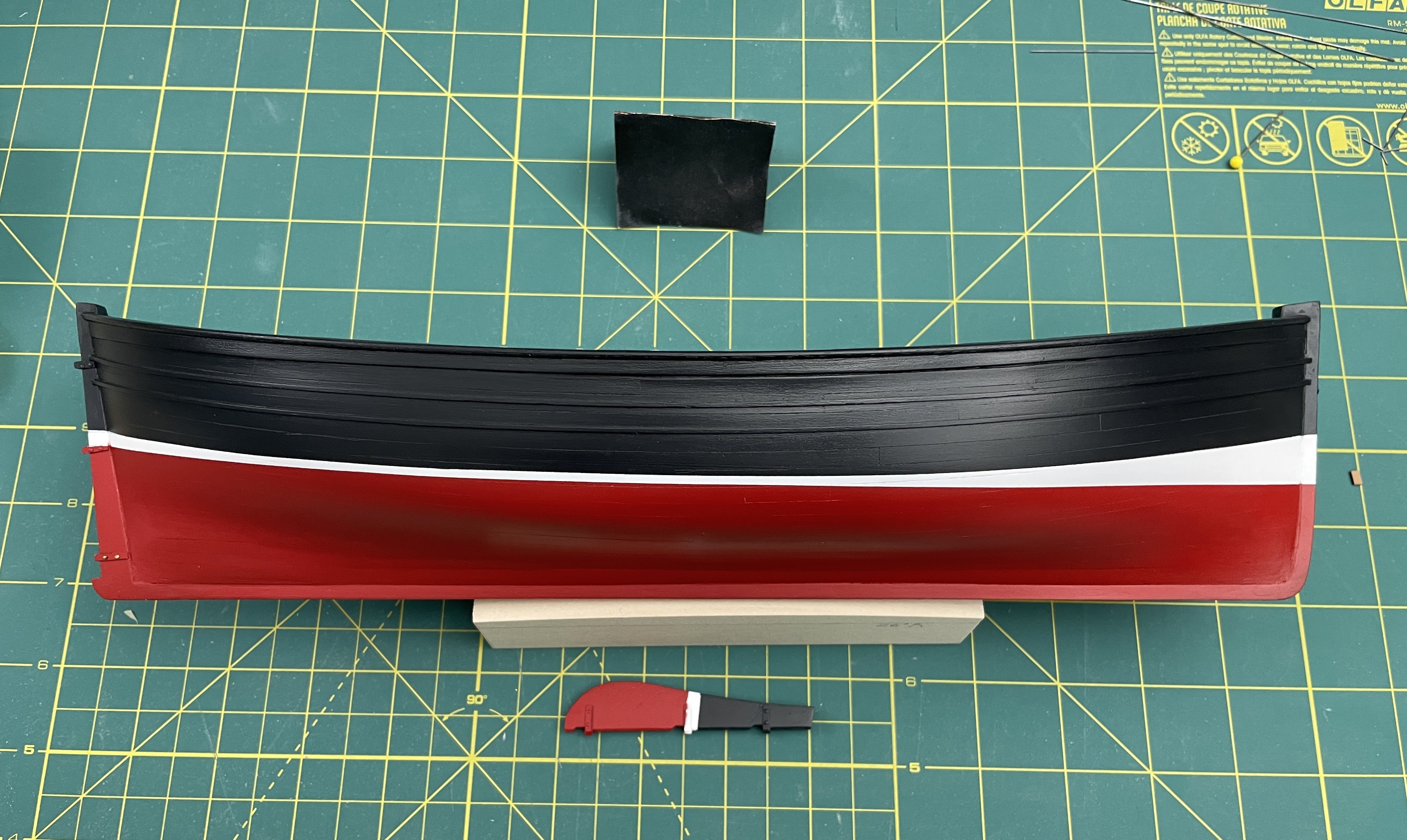
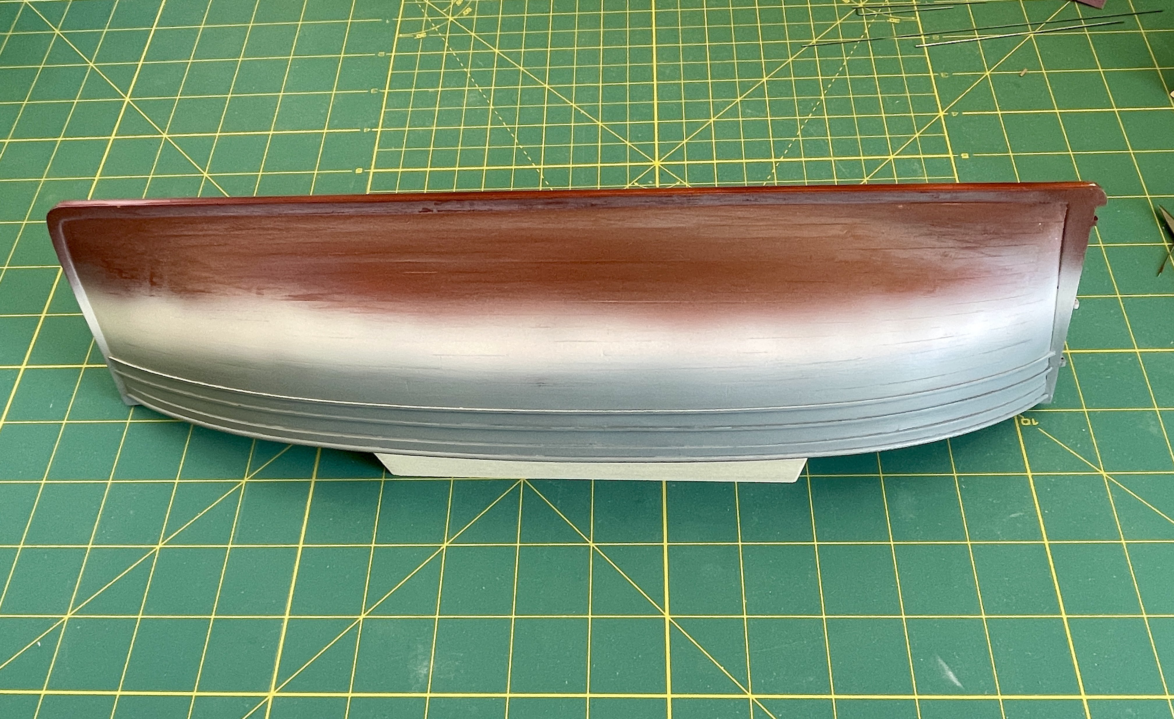
Hull Construction – Painting The build is starting to move out of the “it looks like total s&*t” phase! 😊 Because it’s usually easier covering light colors with darker colors, I painted the boot stripes 1st and then bottom and top sides next. Using acrylic lacquers (Mr. Color (MRC) and Mr. Paint (MRP), I built up each base color with multiple layers for depth. Then based on how to light tended reflect off the hull, and also to add subtle contrast for visual interest, I blended lighter and darker shades over each base color. I figured it’d be fun to include before and after photos of the hull painting. I’ll clear coat the hull after I do minor touch ups and add markings and etc. on the hull. Top Side Colors: MRP-LPG, MRP-255, MRP-348, & MRP-077 Boot Stripes Colors: MRP-LPW, MRP-308, MRC-62, & MRP-97 Bottom Side Colors: MRP-LPR, MRC-327, MRP-250, & MRP-299 Cheers, Jay
- 63 replies
-
- 12
-
-
- Lady Eleanor
- True Vine
- (and 2 more)
-
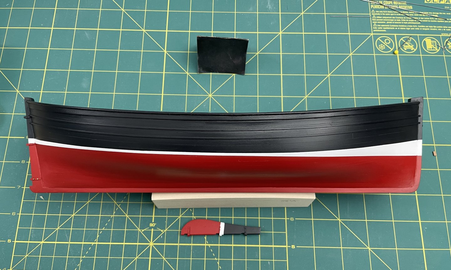
Hull Construction – Rudder & Boot Stripe Rudder Marsh was silent on whether or not Fifie rudders were tapered, so I checked the Reaper and Swan and neither had tapers. Both were beveled, so I added ~ 45 degree bevels to my build’s rudder. If one sticks with the static rudder for Eleanor, Chris’ mortise and tenon design is excellent because it definitely eliminates much of the hassle of installing a movable rudder. Hanging rudders isn’t one of my favorite parts of a built—my experience has been that they often are quite fiddly and PITAs—and making a moveable rudder for the build was no exception and was self-inflicted. Boot Stripe Marking boot stripes also isn’t a favorite build activity because they are another facet of a build that in my experience is often also fiddly and a PITA…my work the on the build’s stripes were no exception. Using the plans for the boot stripe top and bottom locations and then marking off those off with a waterline tool did not work for me. The geometry of where and how a hull is positioned affects marking out a stripe; my kit’s acrylic stand was warped, so it was lopsided and trying to use it as an aid for marking the hull was untenable. I checked a couple of other Eleanor logs and some folks had challenges with marking like I did and some apparently did not (their logs were silent). In the end, I used plan locations for the stripes and then faired each stripe by eye using the methods one uses for lining off a hull. While that method took a while, it ended up taking less time than did trying to use a height gauge and for me produced visually pleasing results. Cheers, Jay

- 63 replies
-
- 6
-
-
- Lady Eleanor
- True Vine
- (and 2 more)
.JPG.543741b80c26eb8c01b9e82d87e9c13c.JPG)