SUBaron
-
Posts
197 -
Joined
-
Last visited
Content Type
Profiles
Forums
Gallery
Events
Everything posted by SUBaron
-
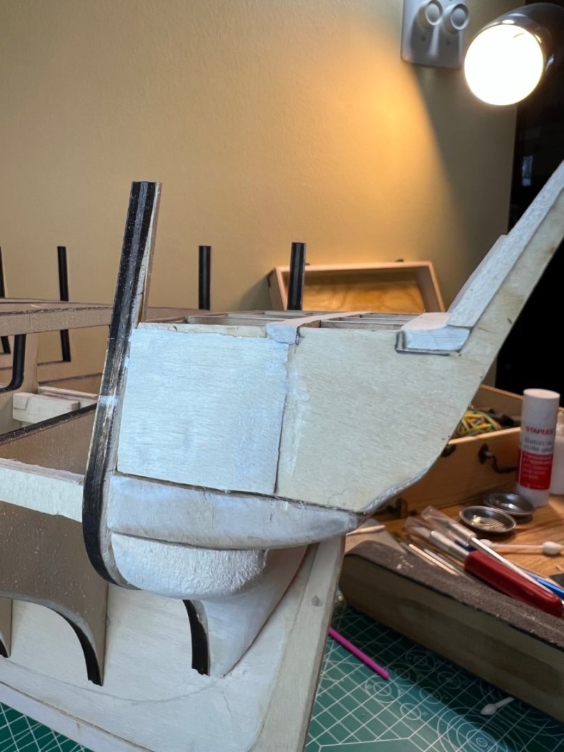
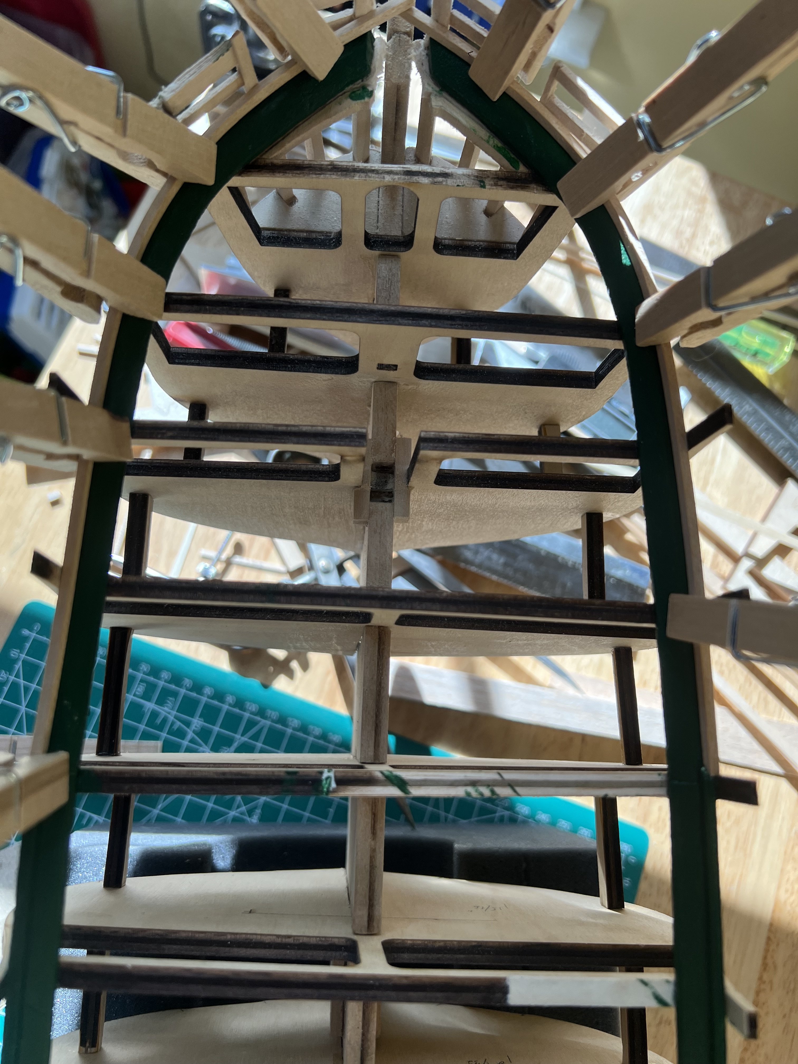
I’ve completed installing the starboard and port inner planking. I will finish sanding and painting later. My bow section needs some work and I’m thinking of cutting some planking away and creating a “plate”of sorts, fitted to the bowsprit. Not sure how I let it get so messy - The area needs some cleaning up. I followed Hunt’s suggestion to use shorter plank sections and I think that threw me a bit toward the bow.
-
@JSGerson@Der Alte Rentner Jon and Peter - thank you for sharing your pictures! Mystic is such an enchanting place. I can’t wait to go back. I’ve never done any true blue water voyaging - but I did travel for 2 weeks around the Galápagos Islands. It was in a 100’ modern(ish) yacht, but it was easy to picture Darwin making entries in his travel diary!
-
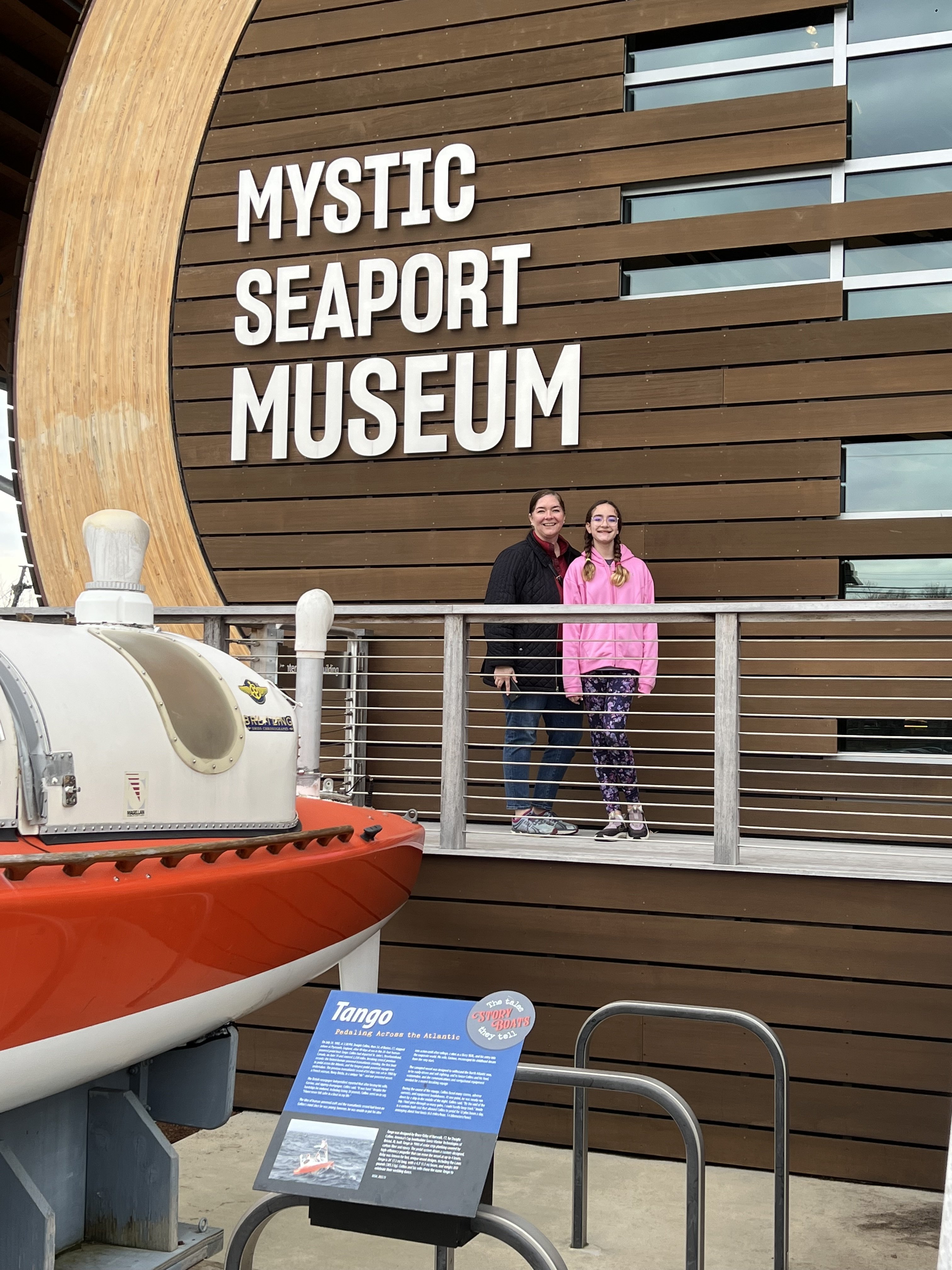
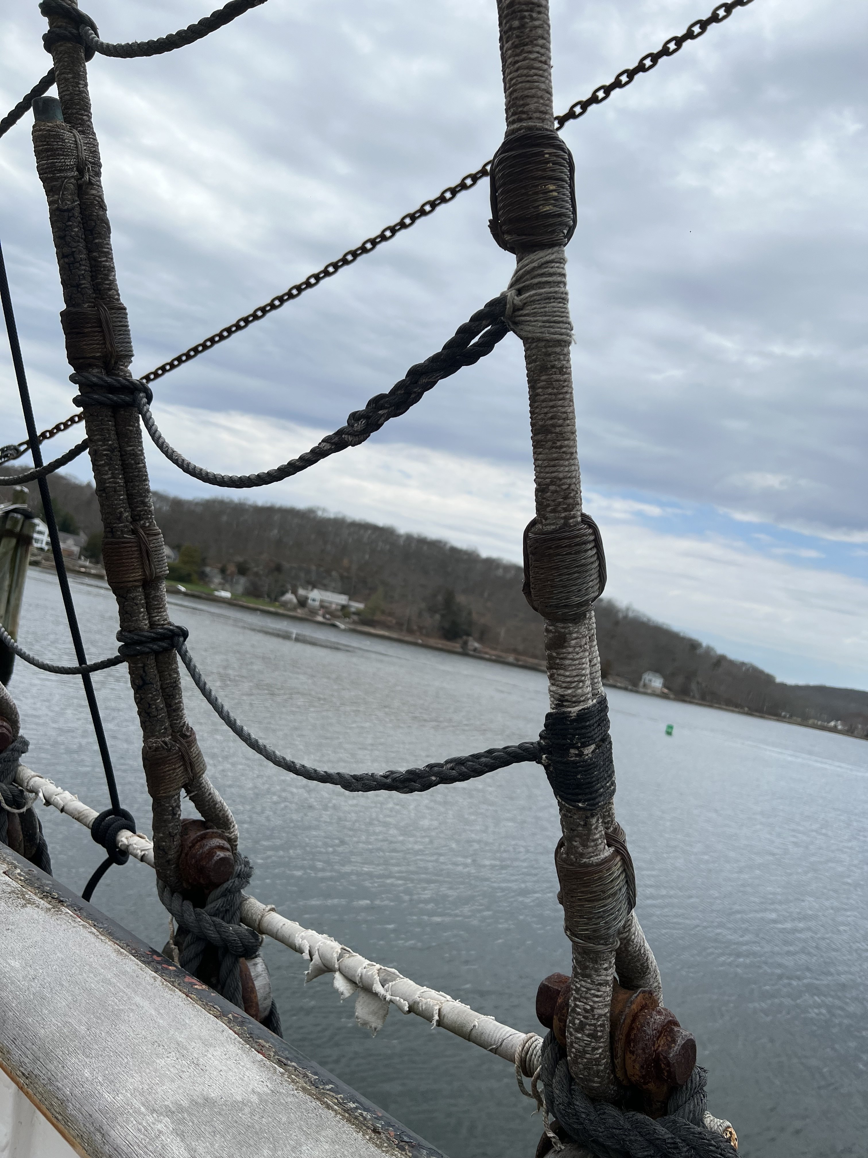
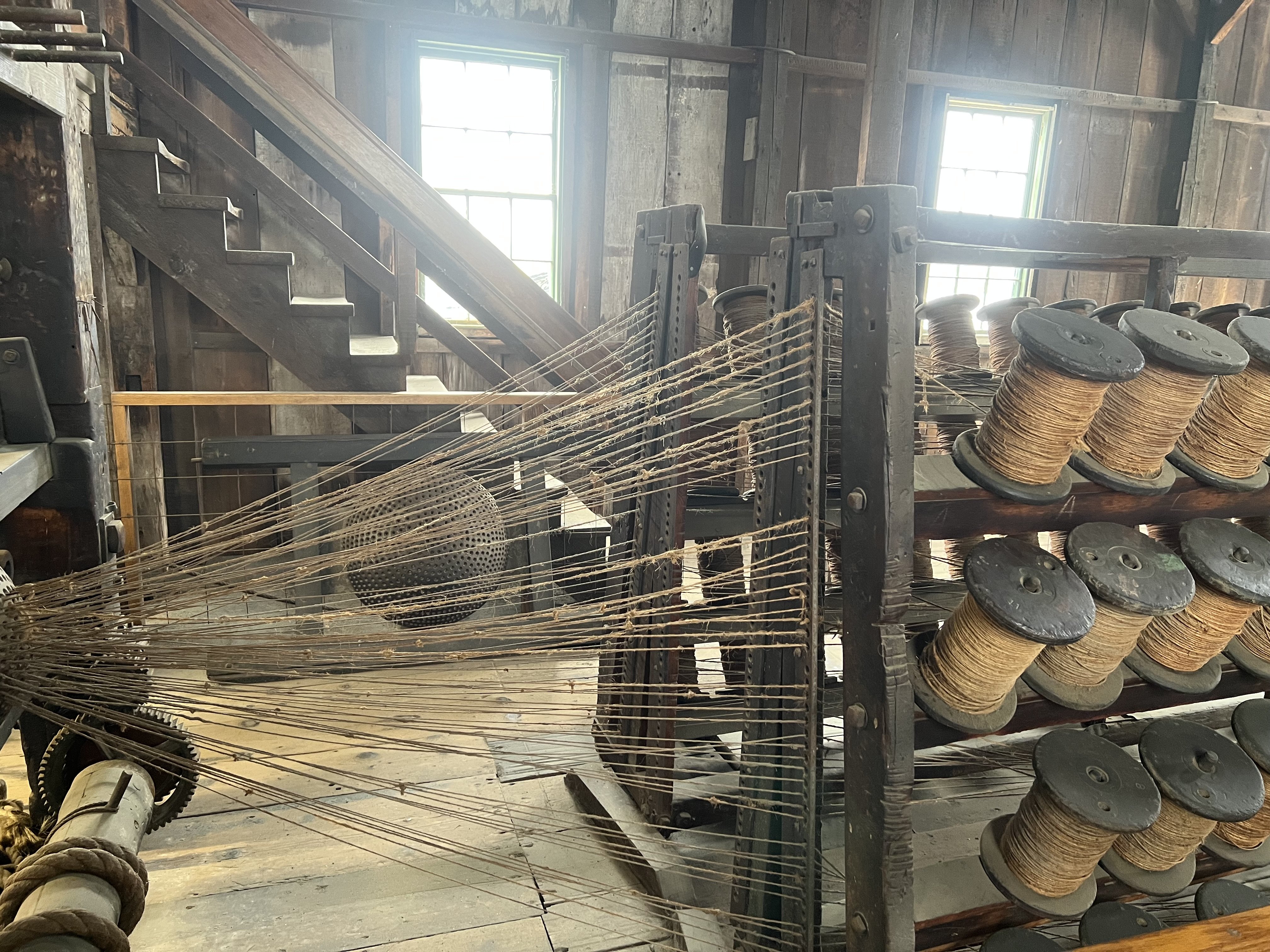
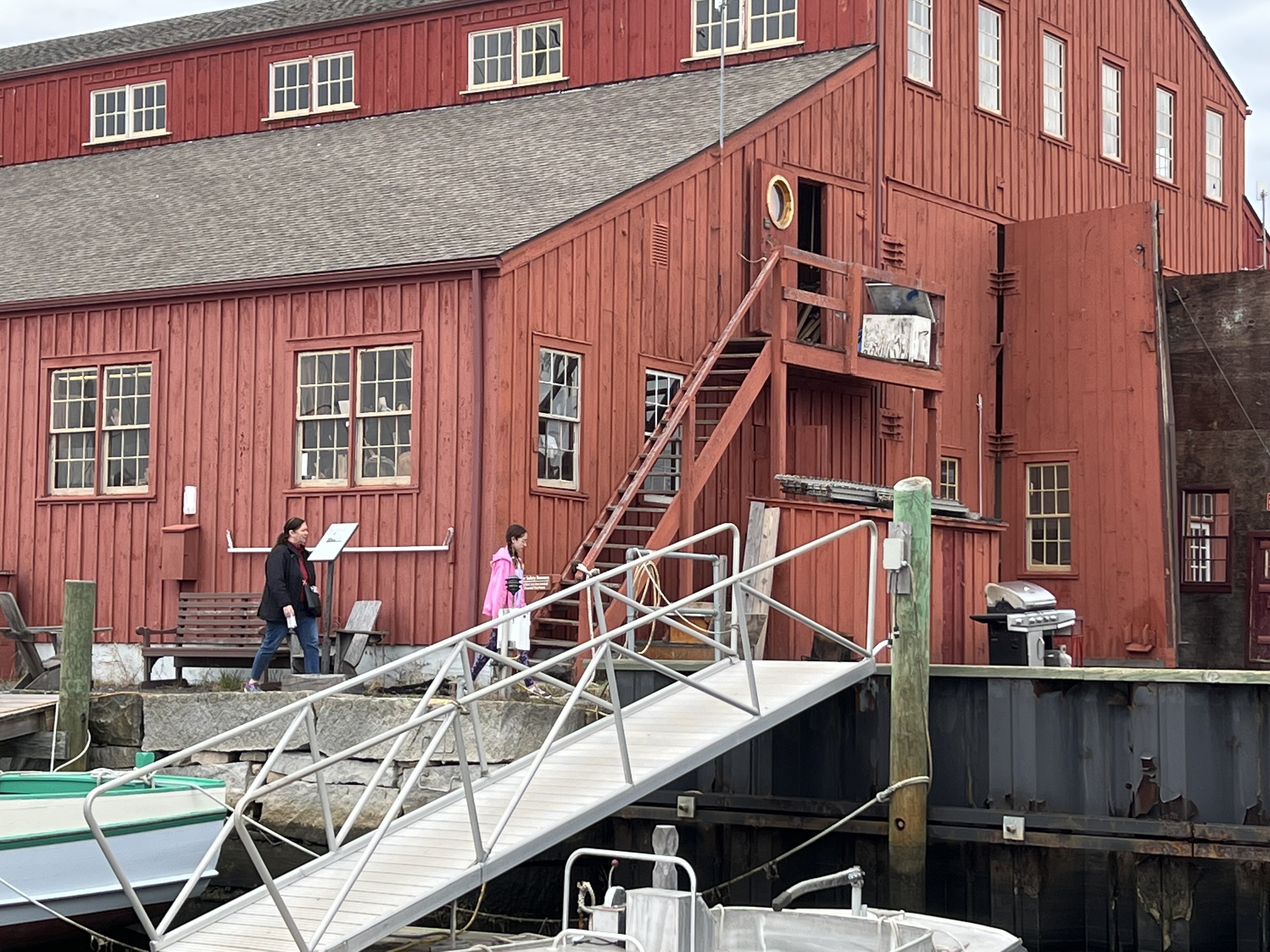
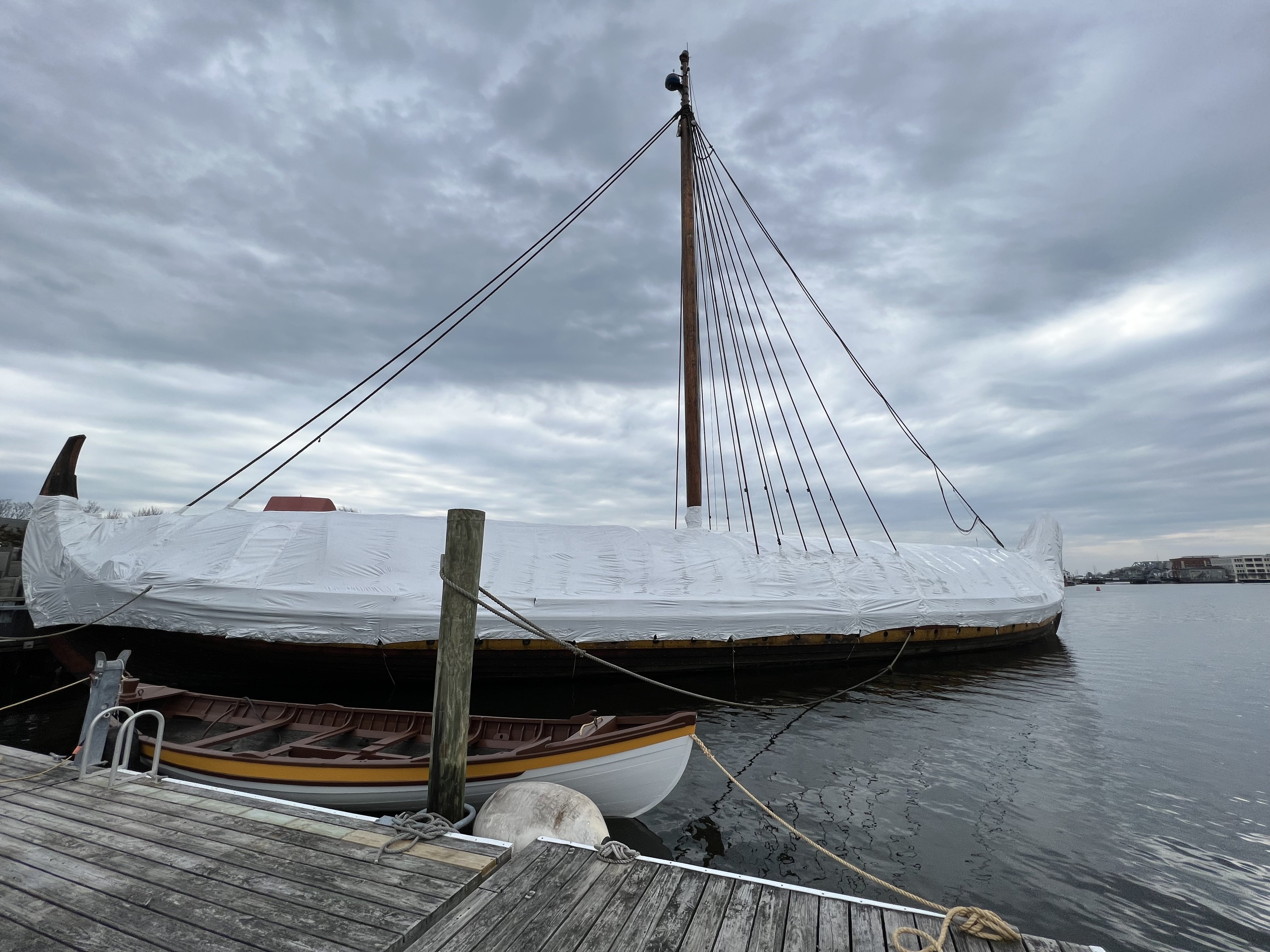
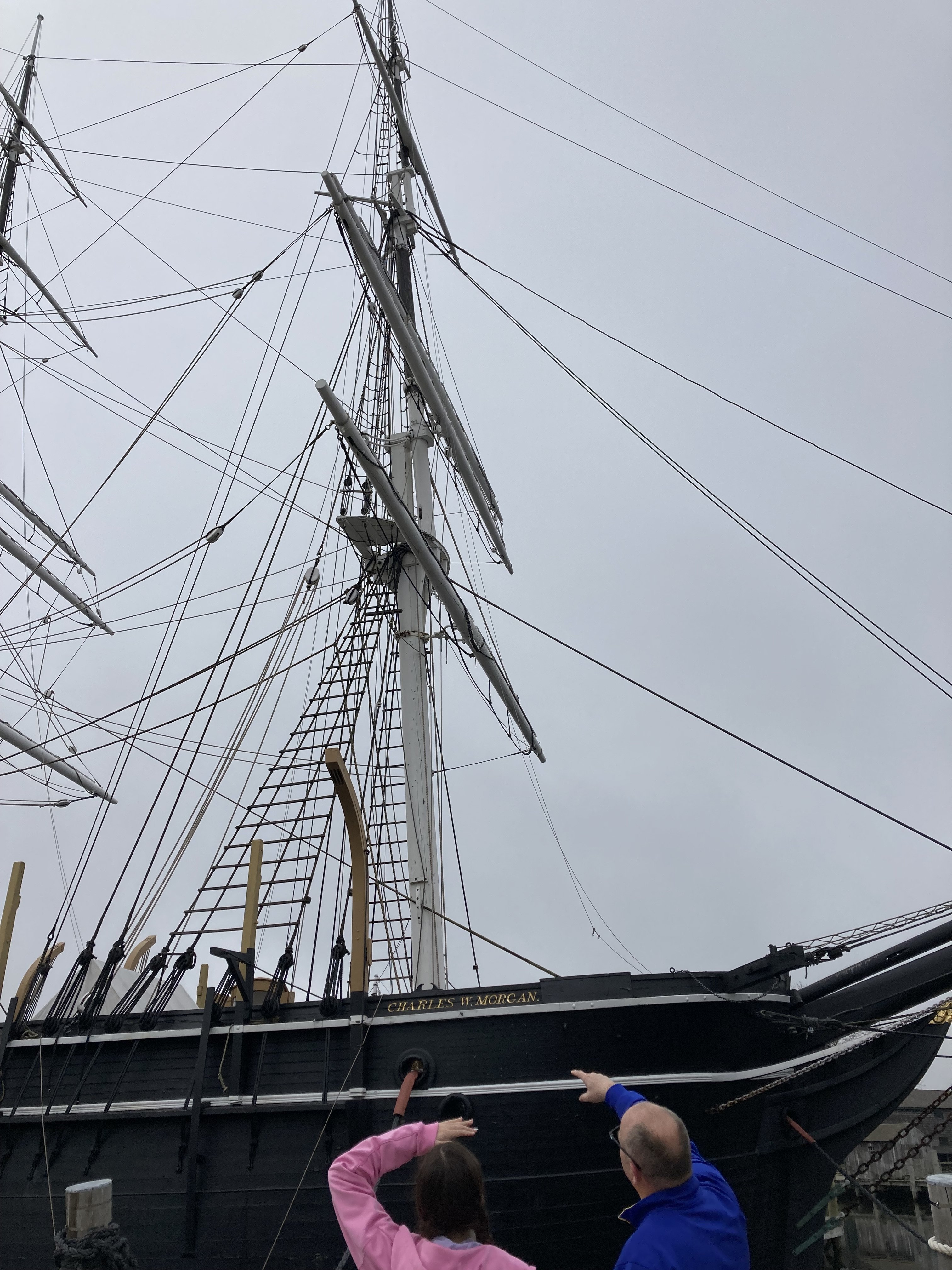
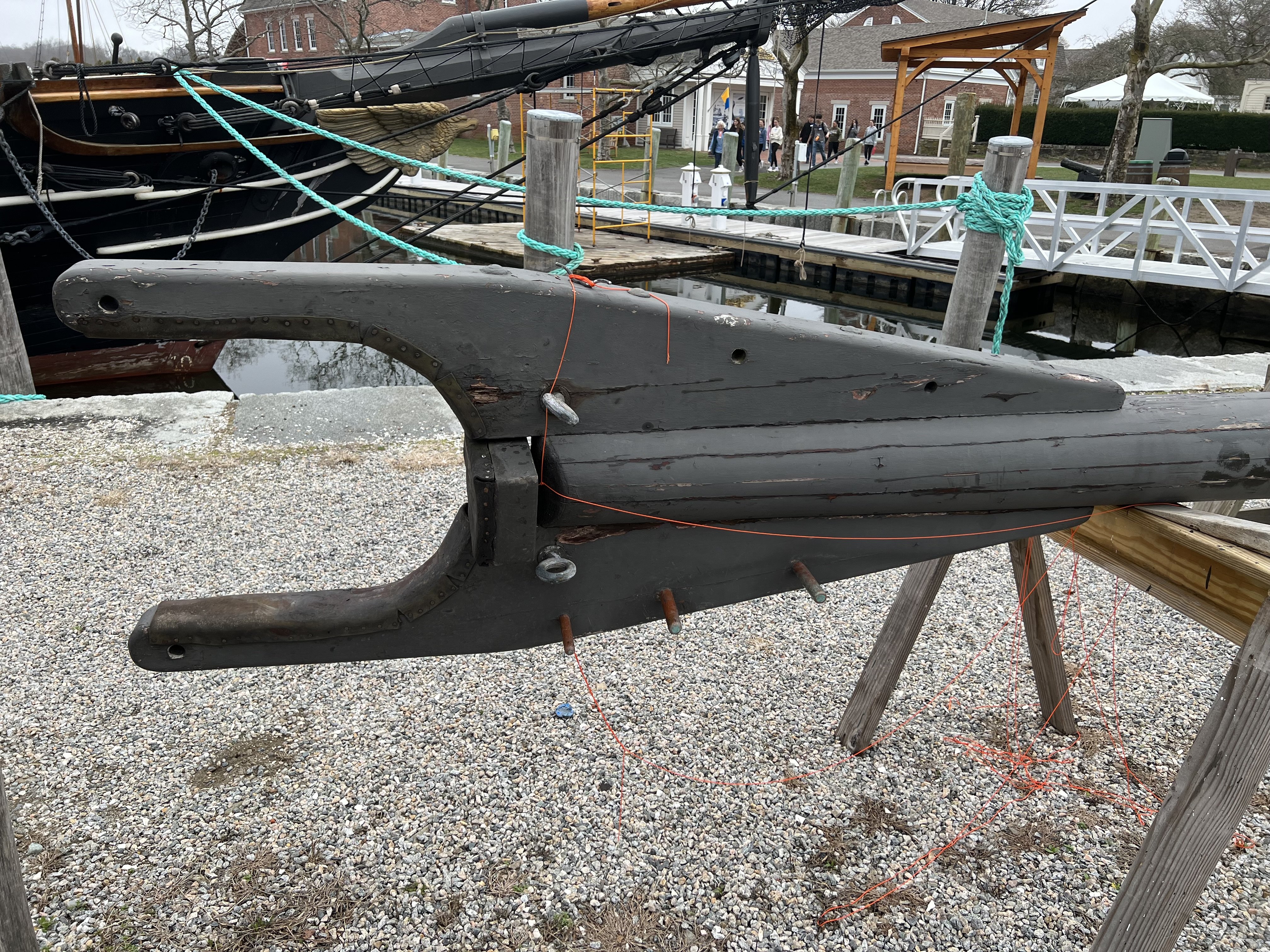
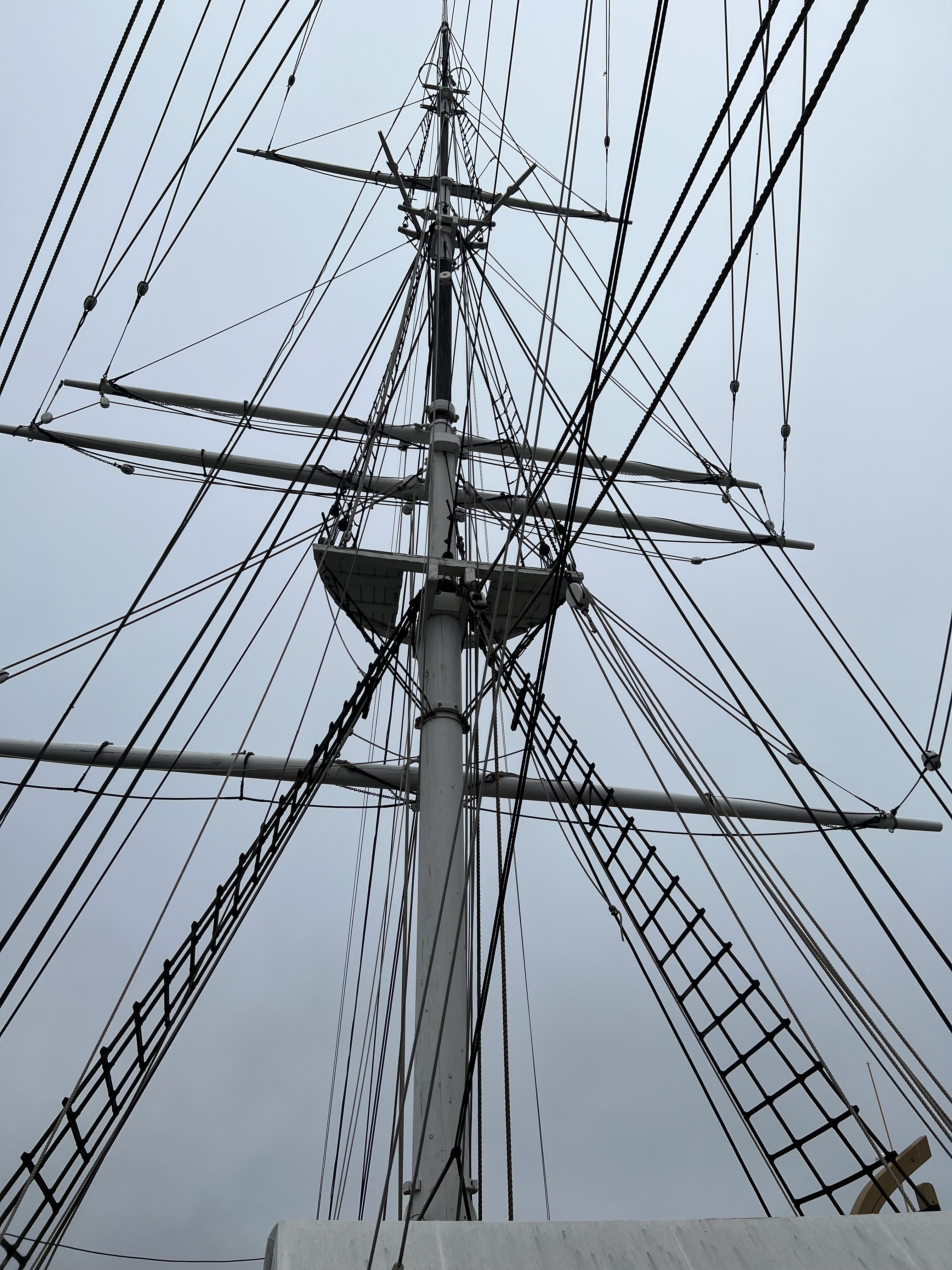
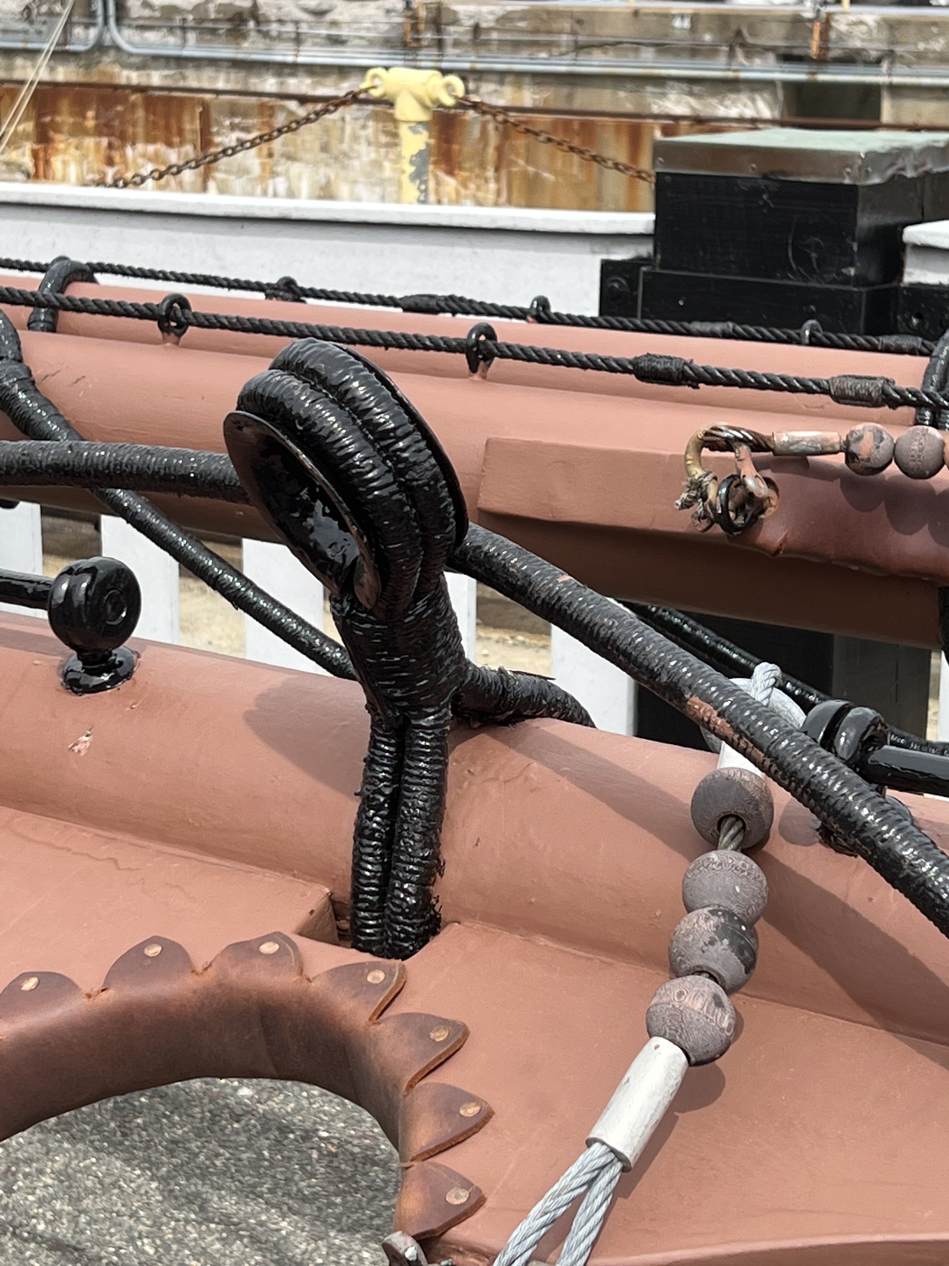
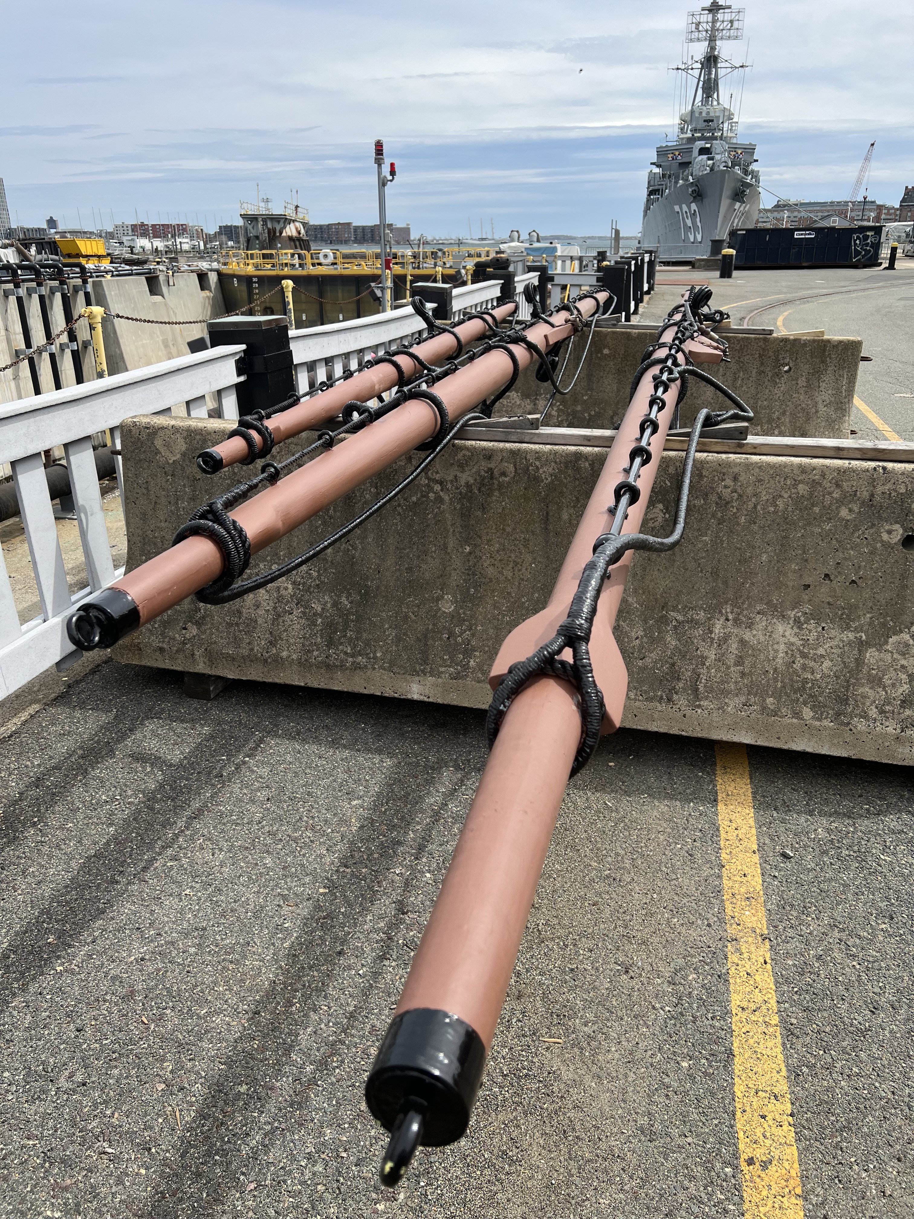
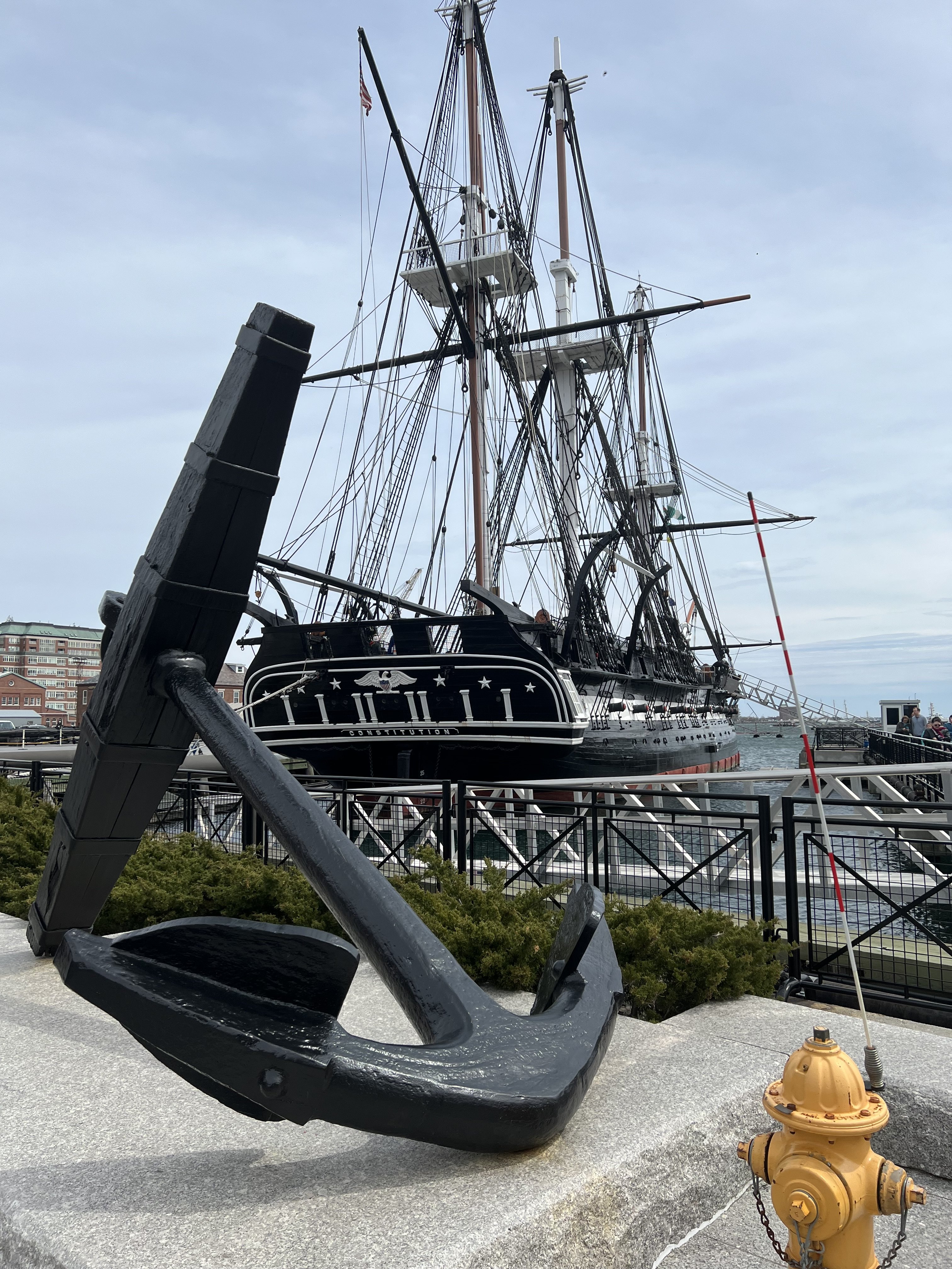
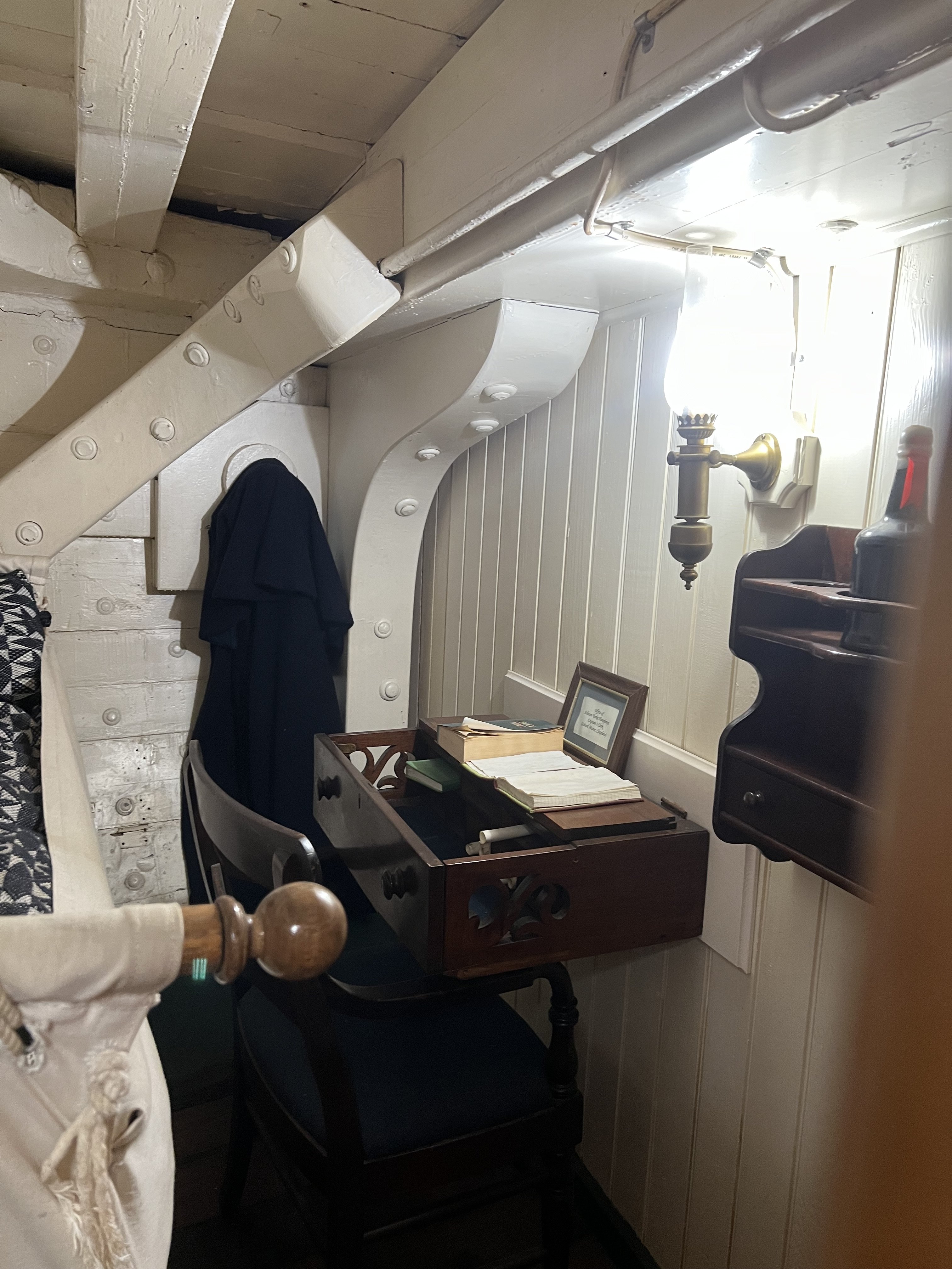
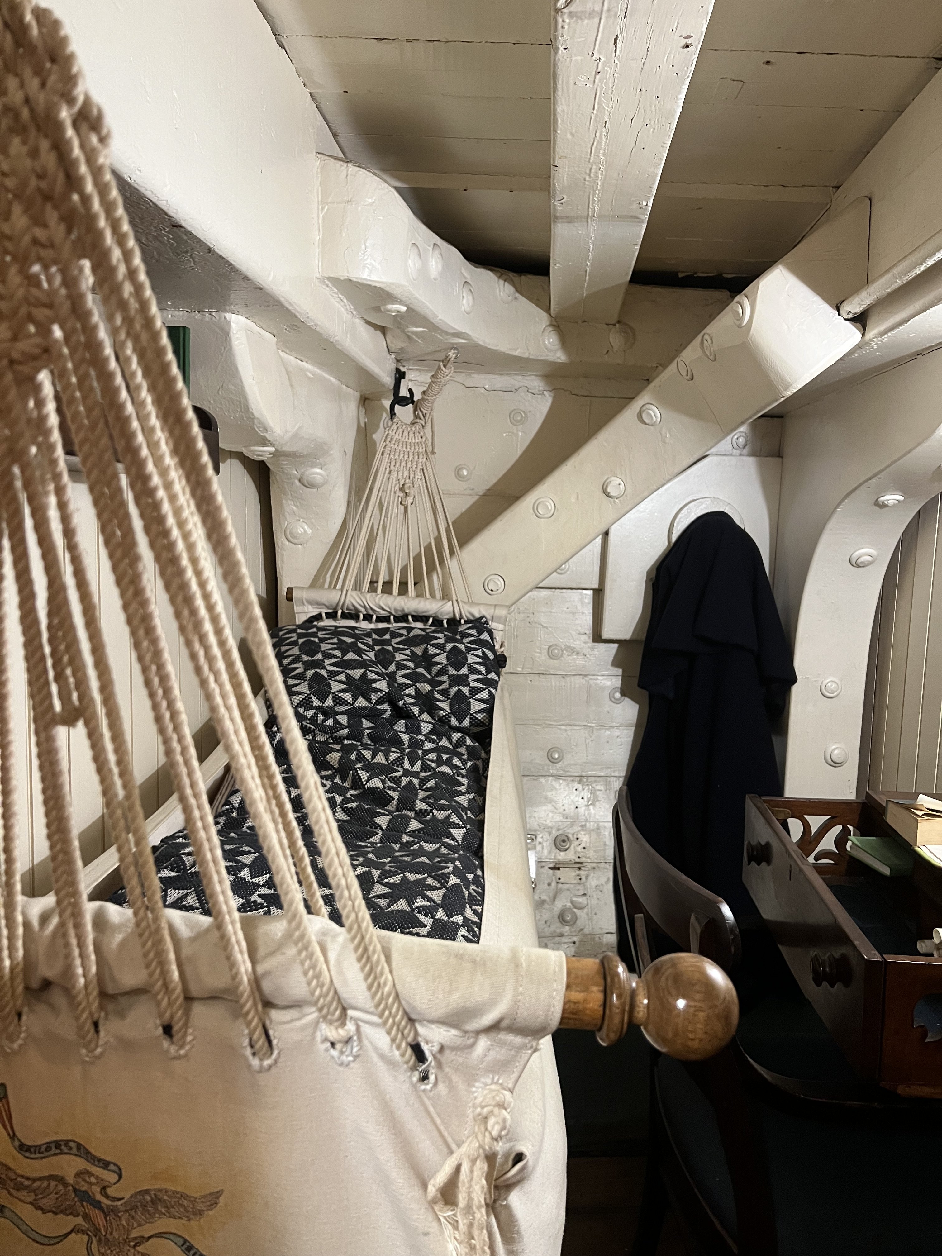
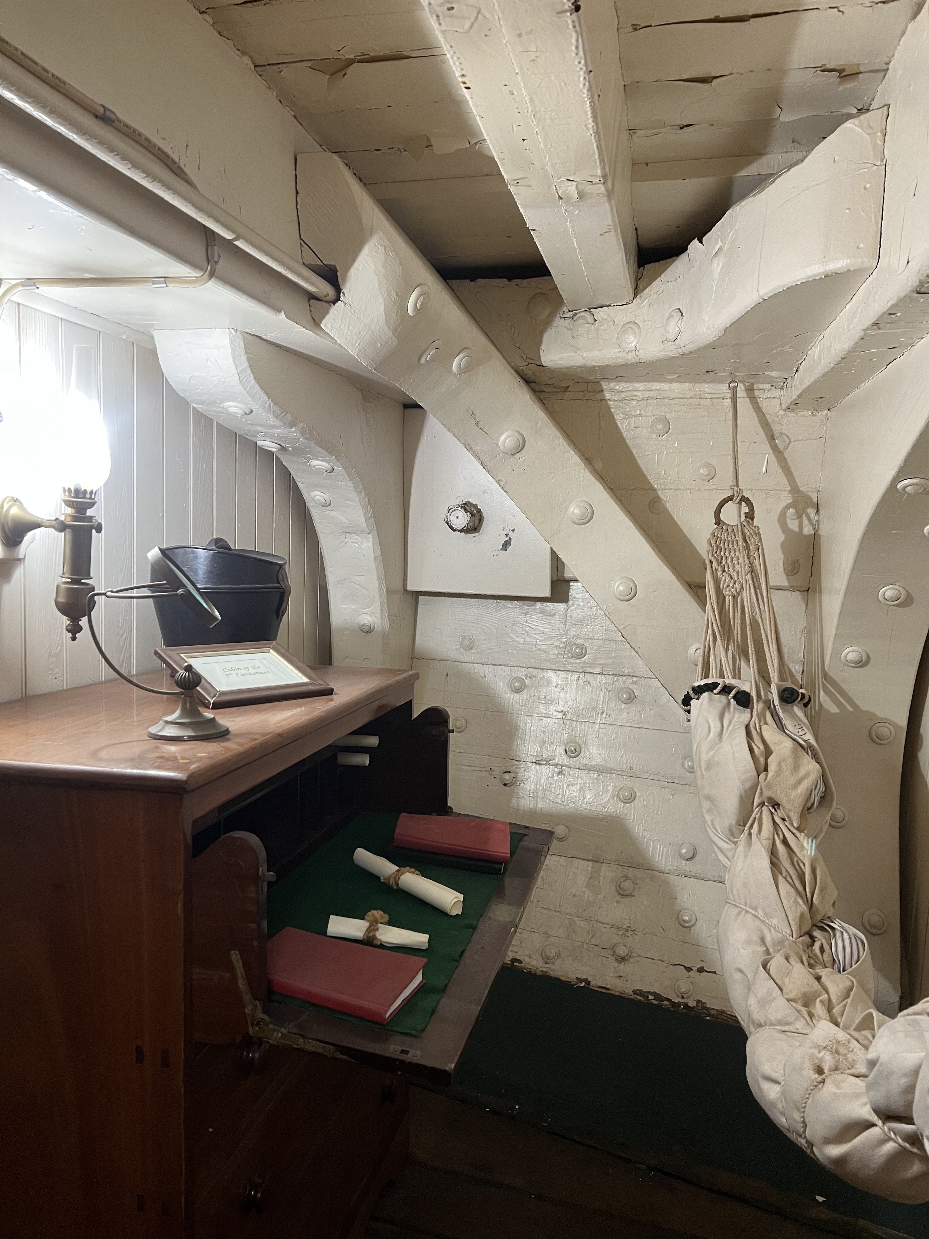
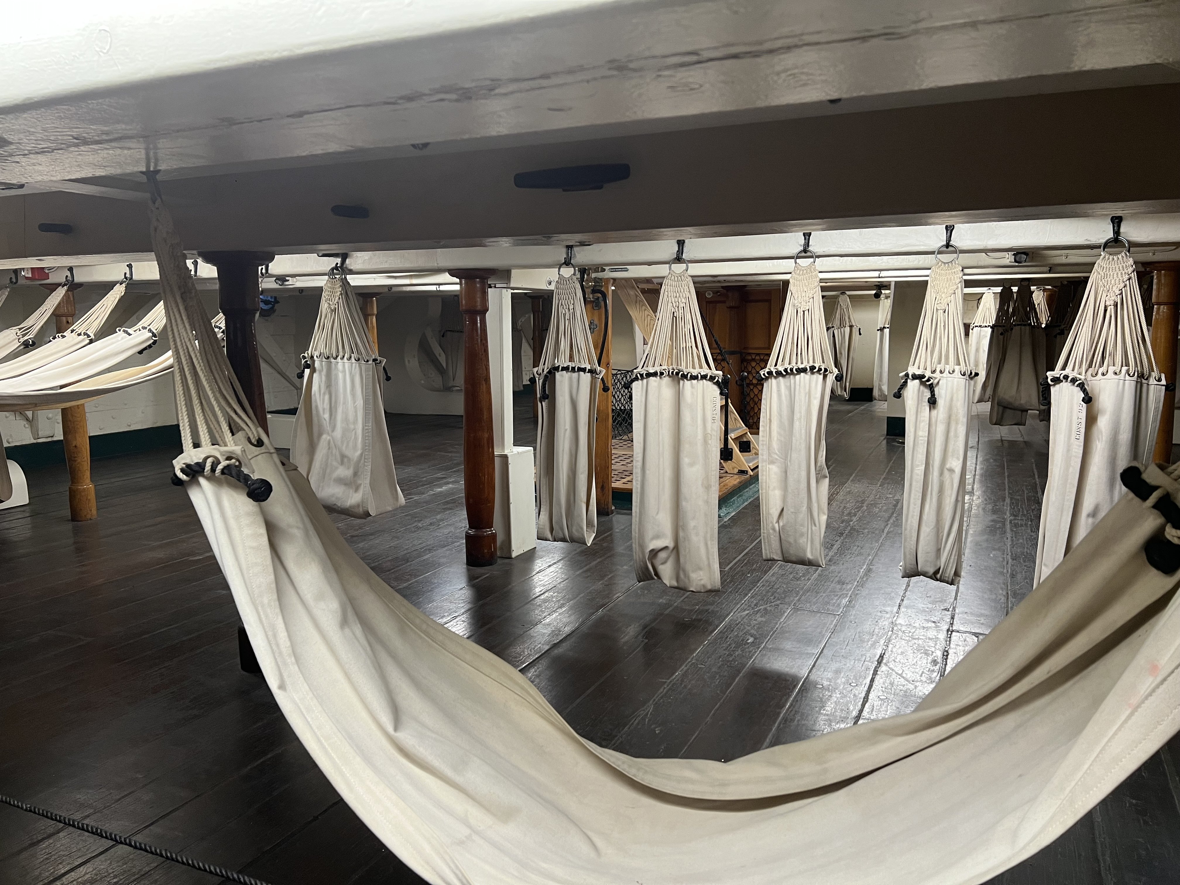
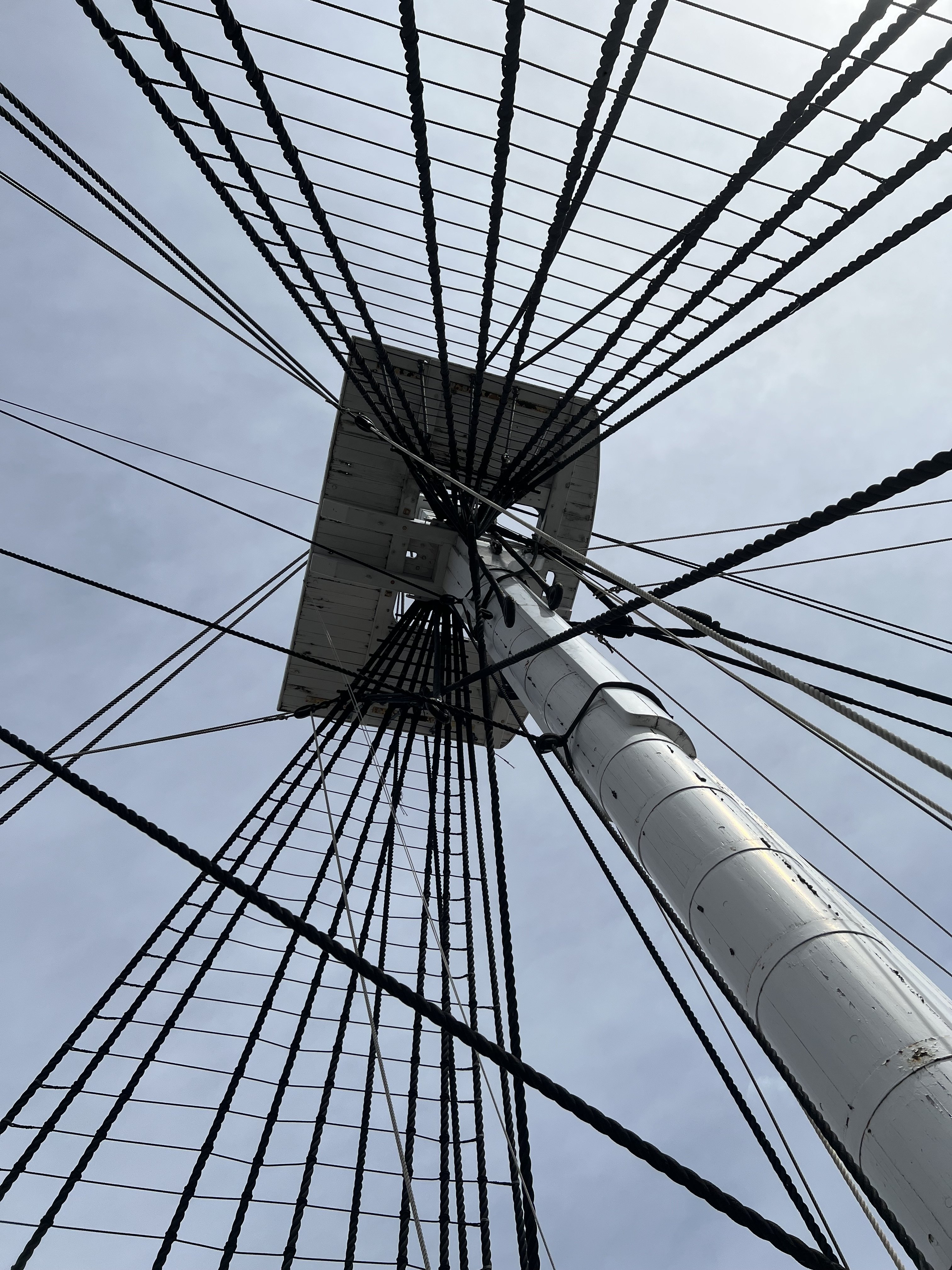
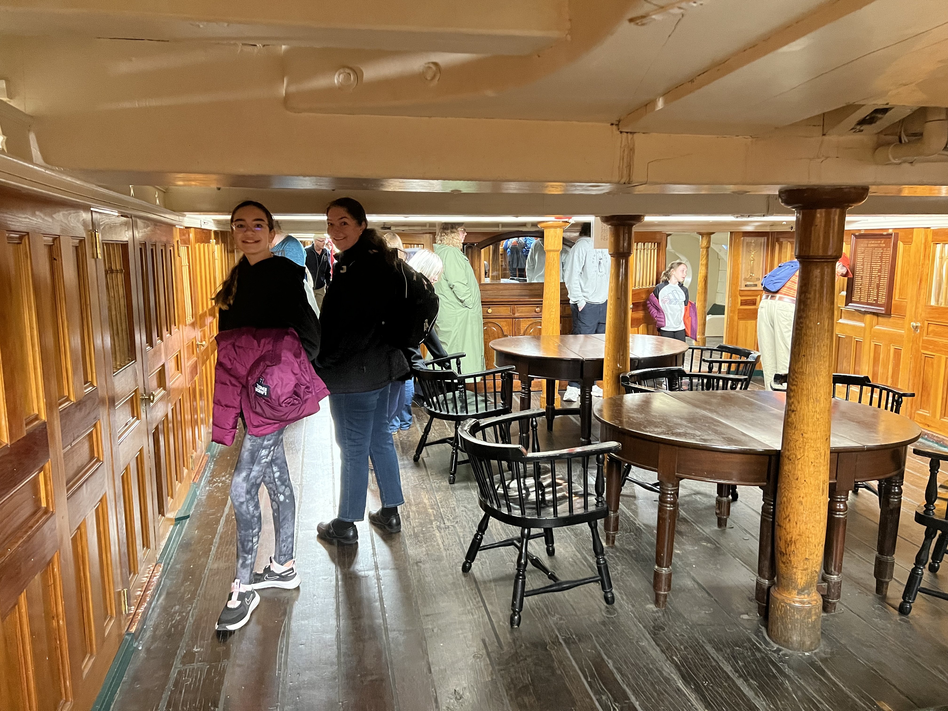
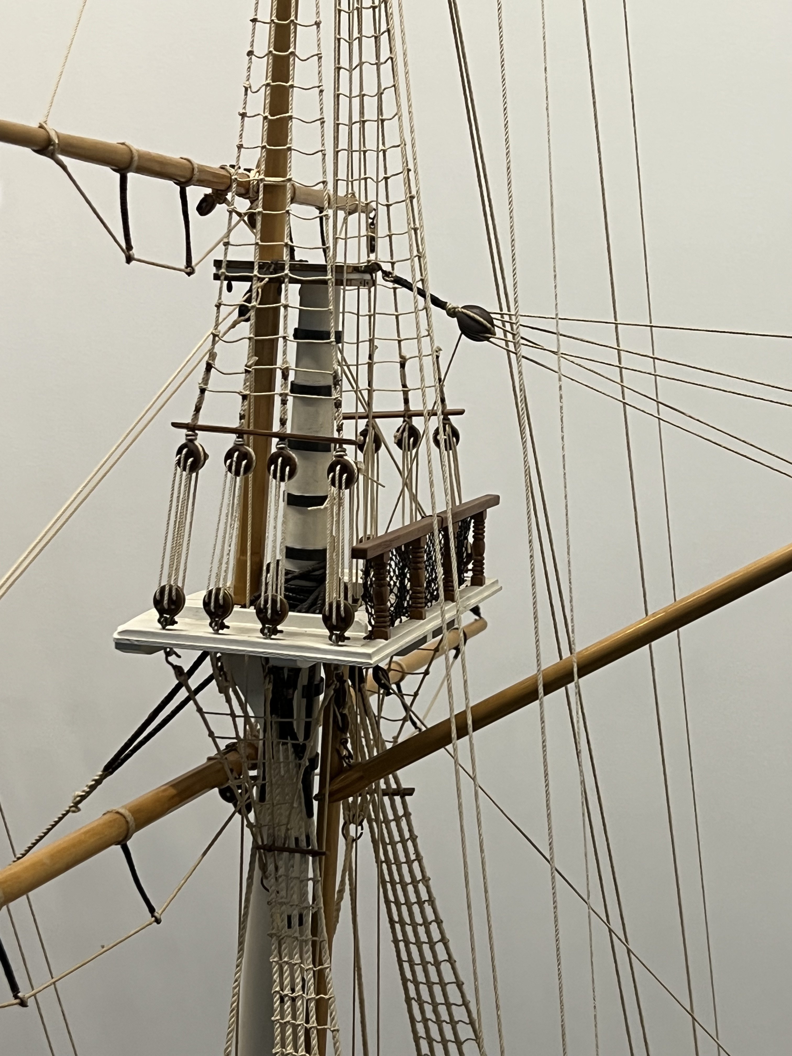
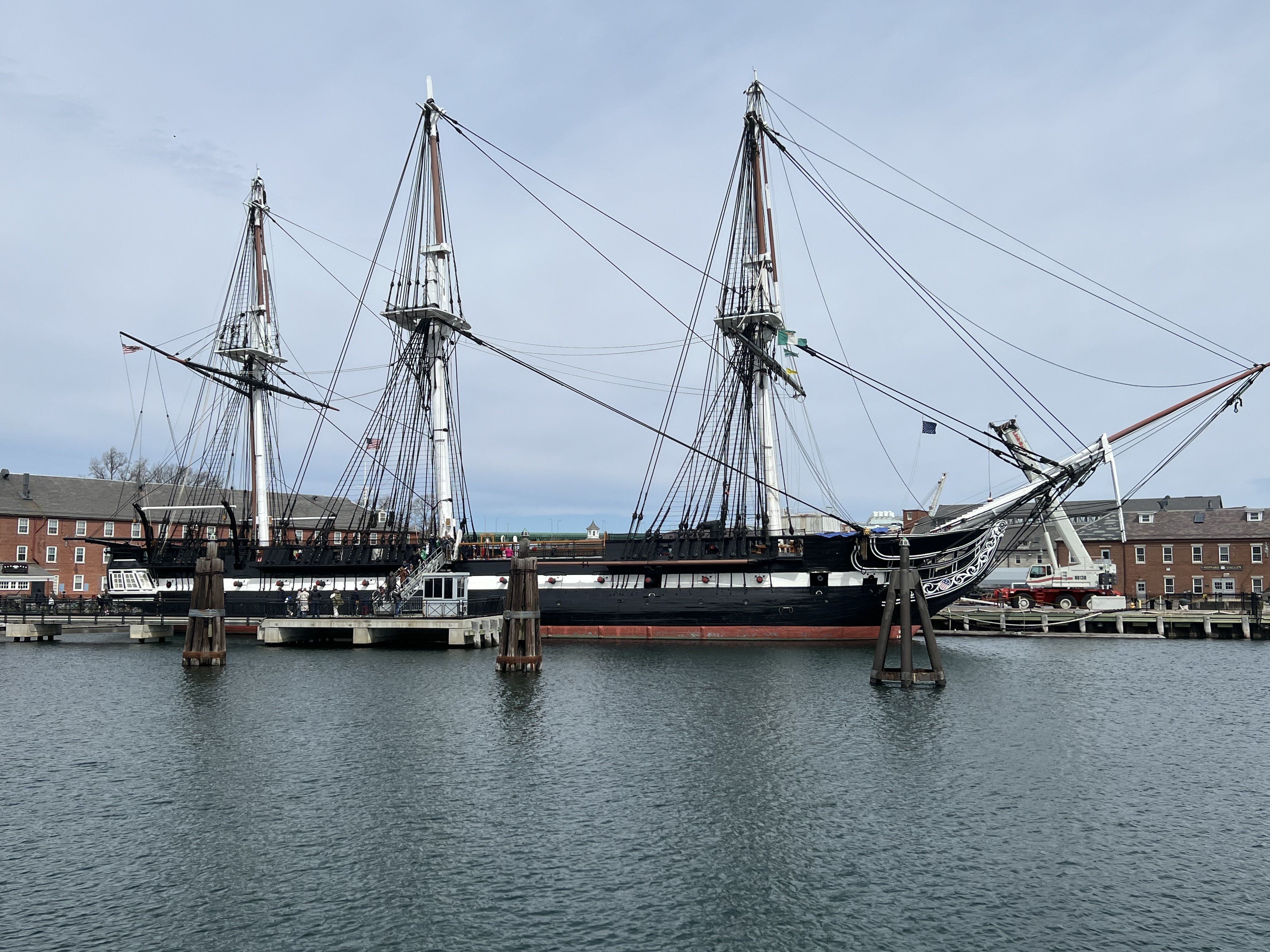
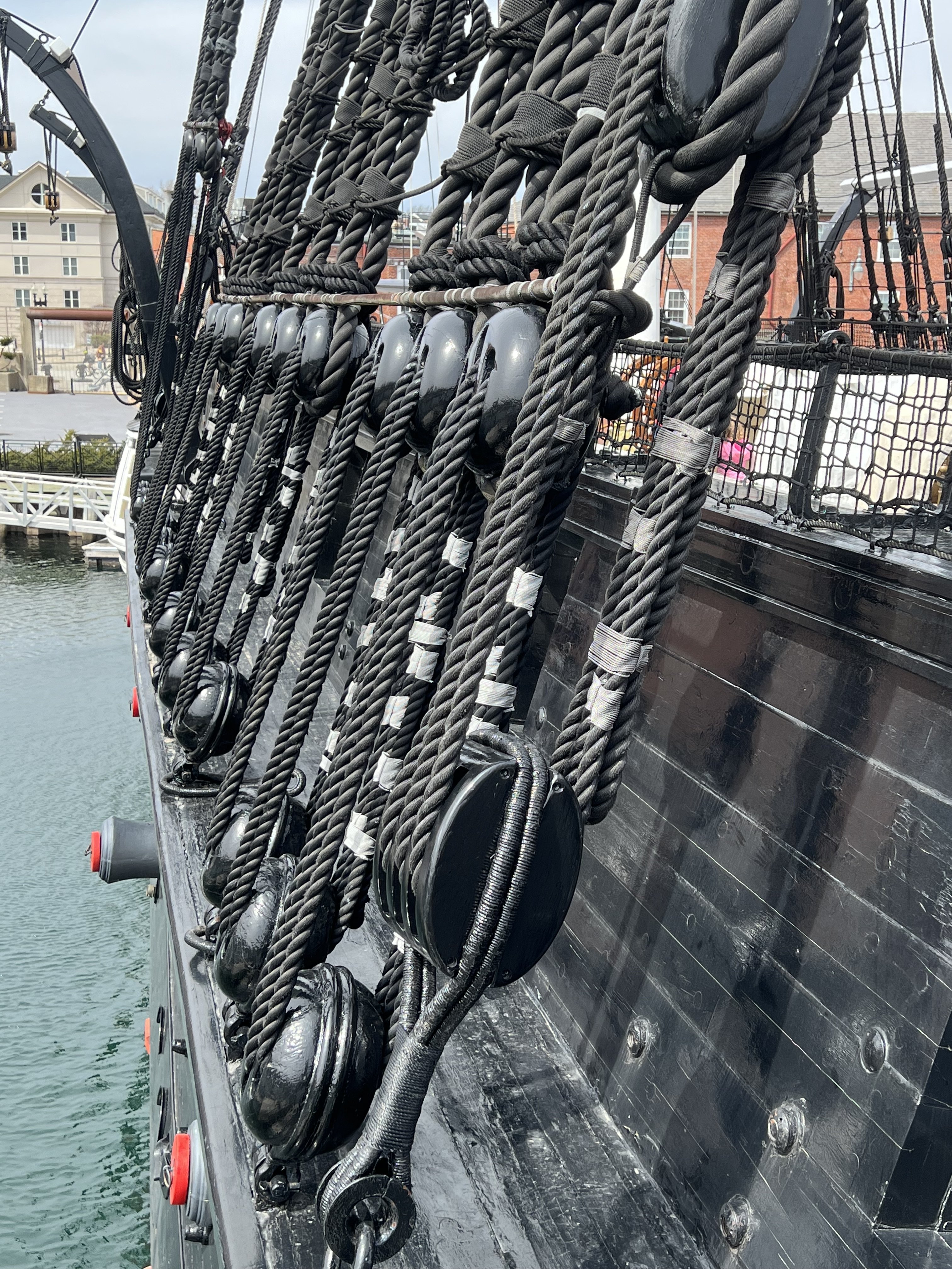
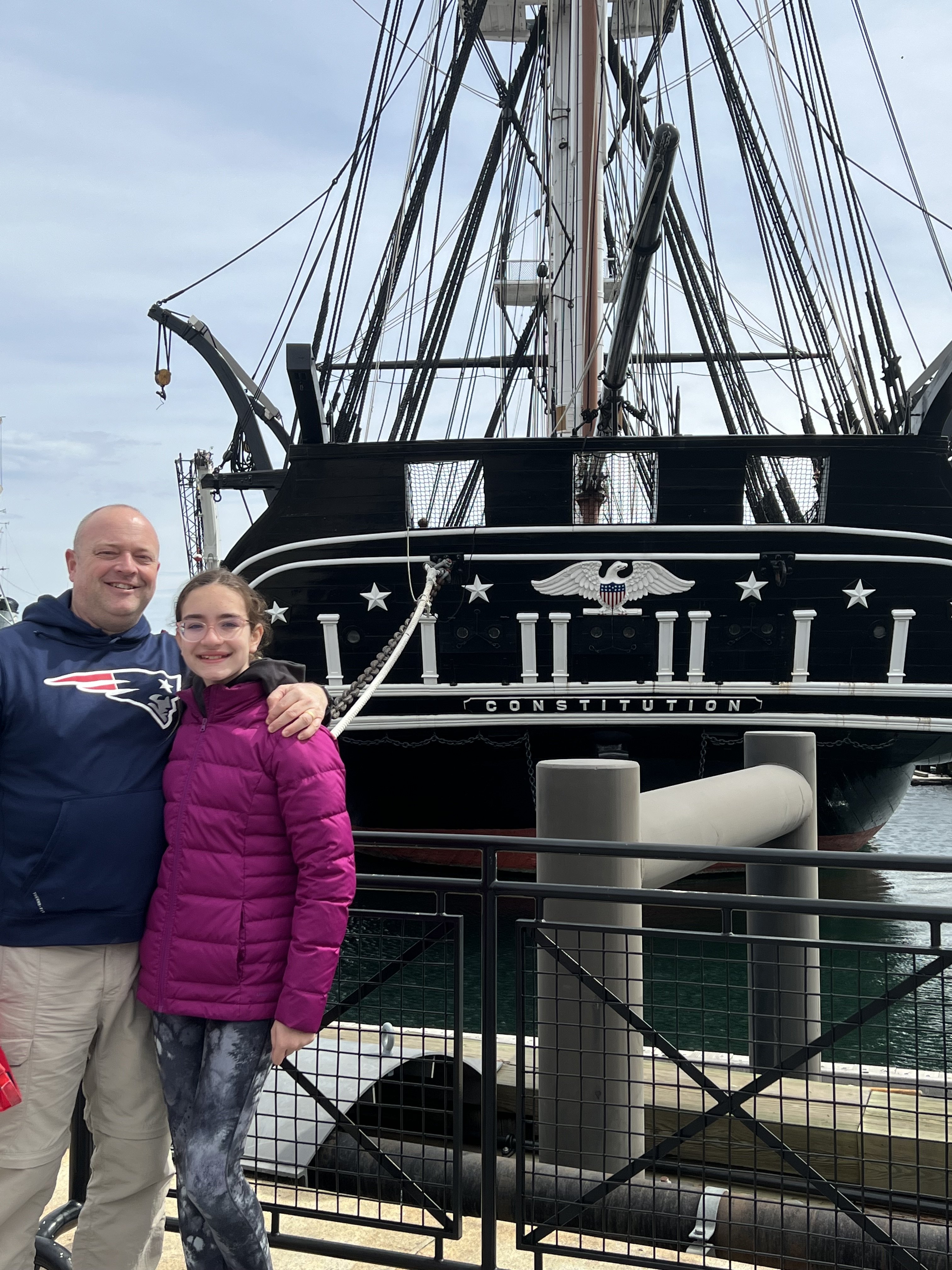
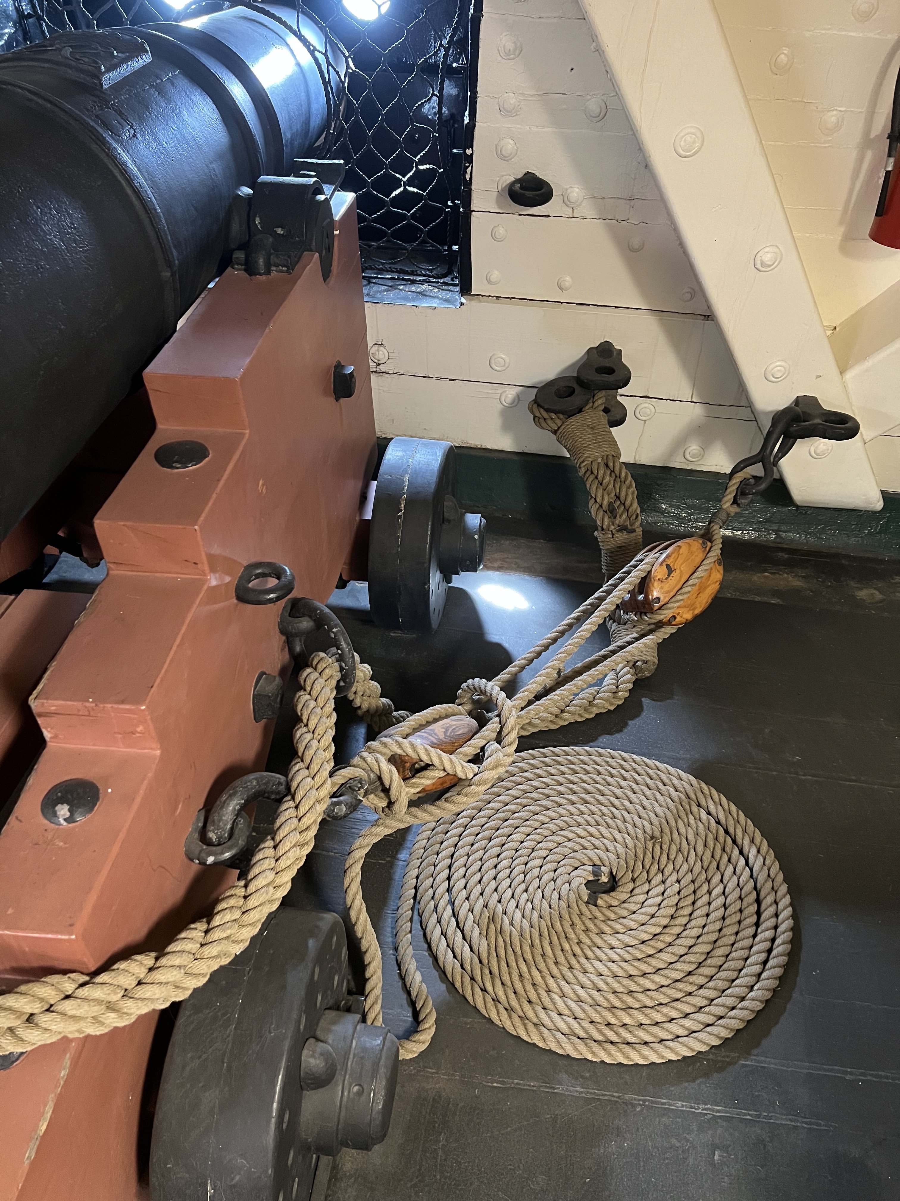
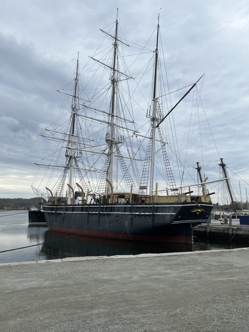
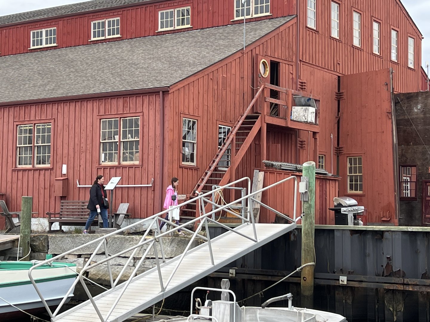
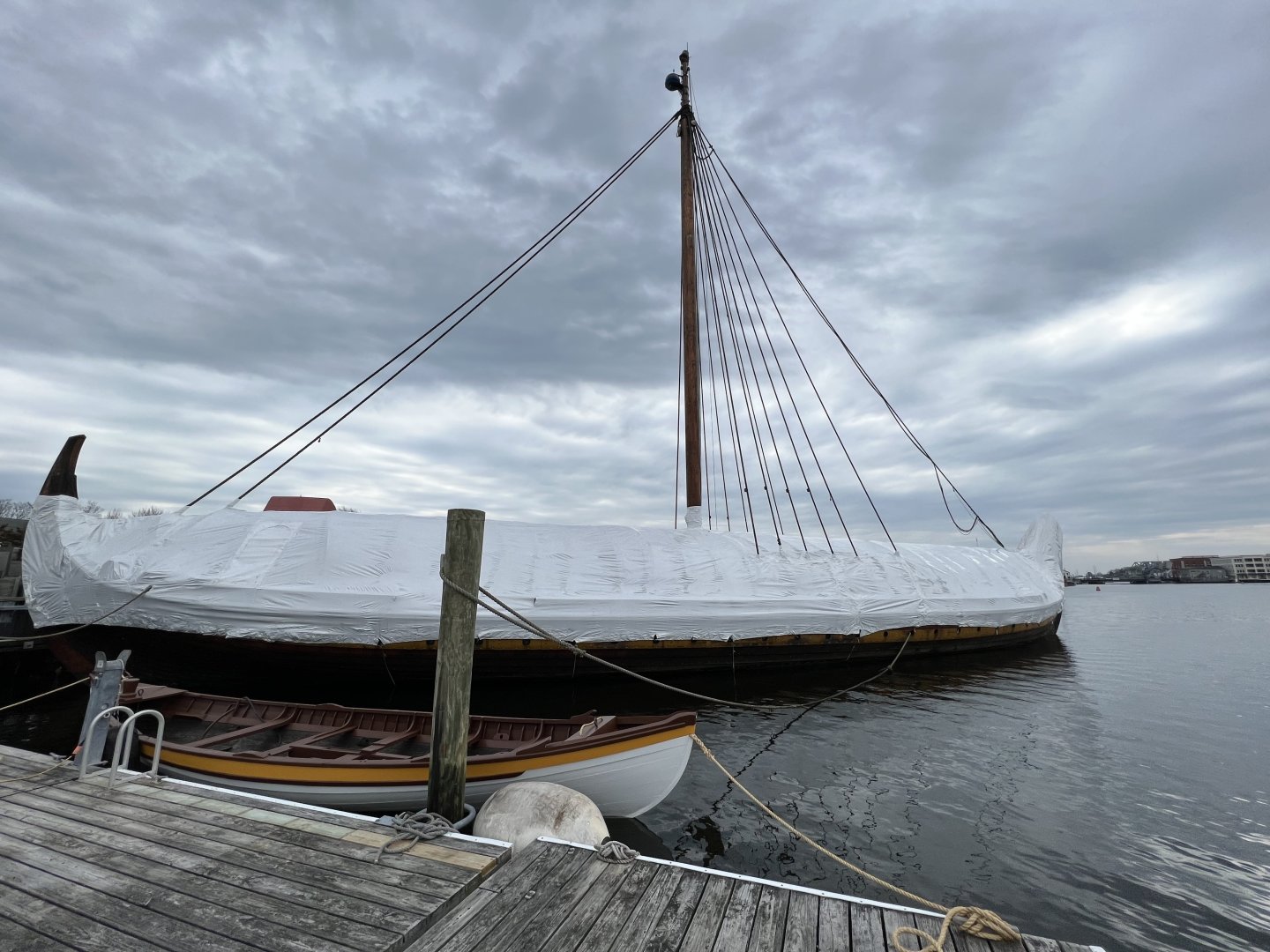
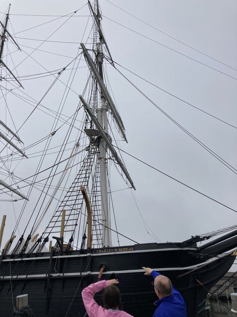
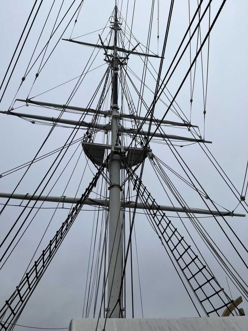
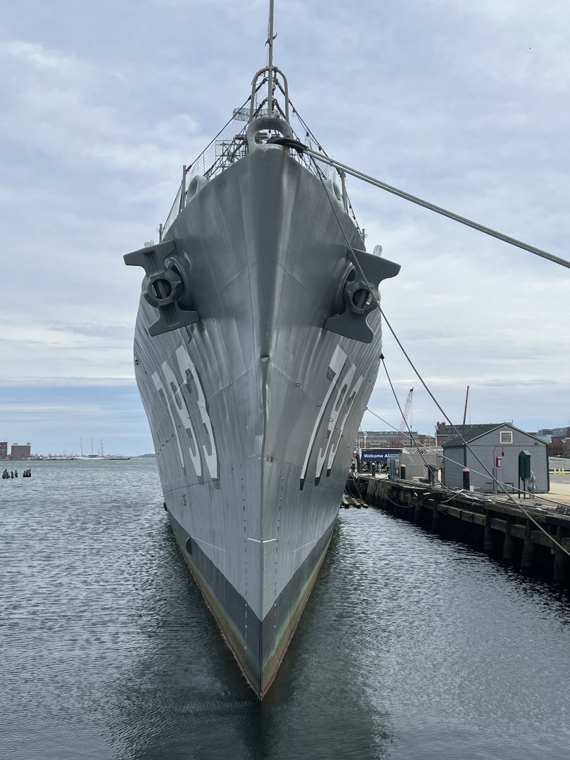
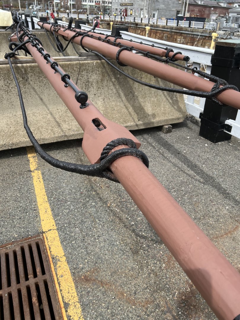
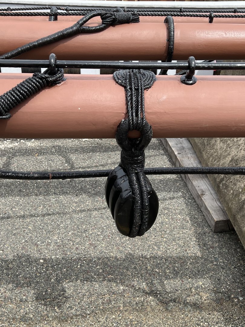
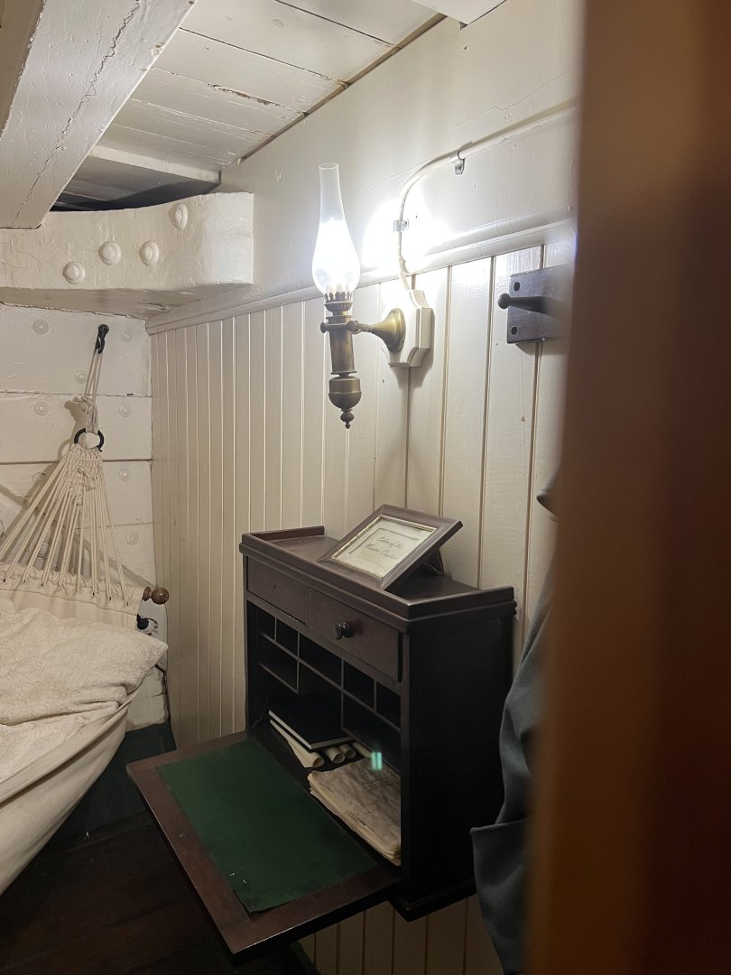
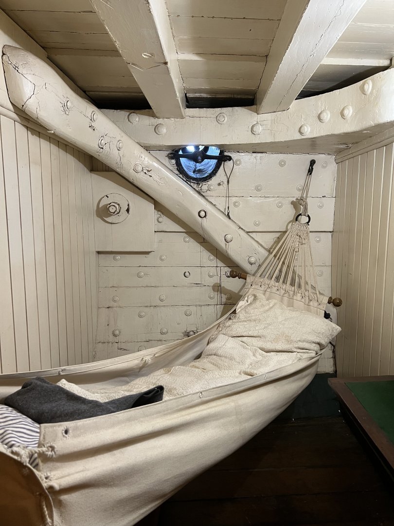
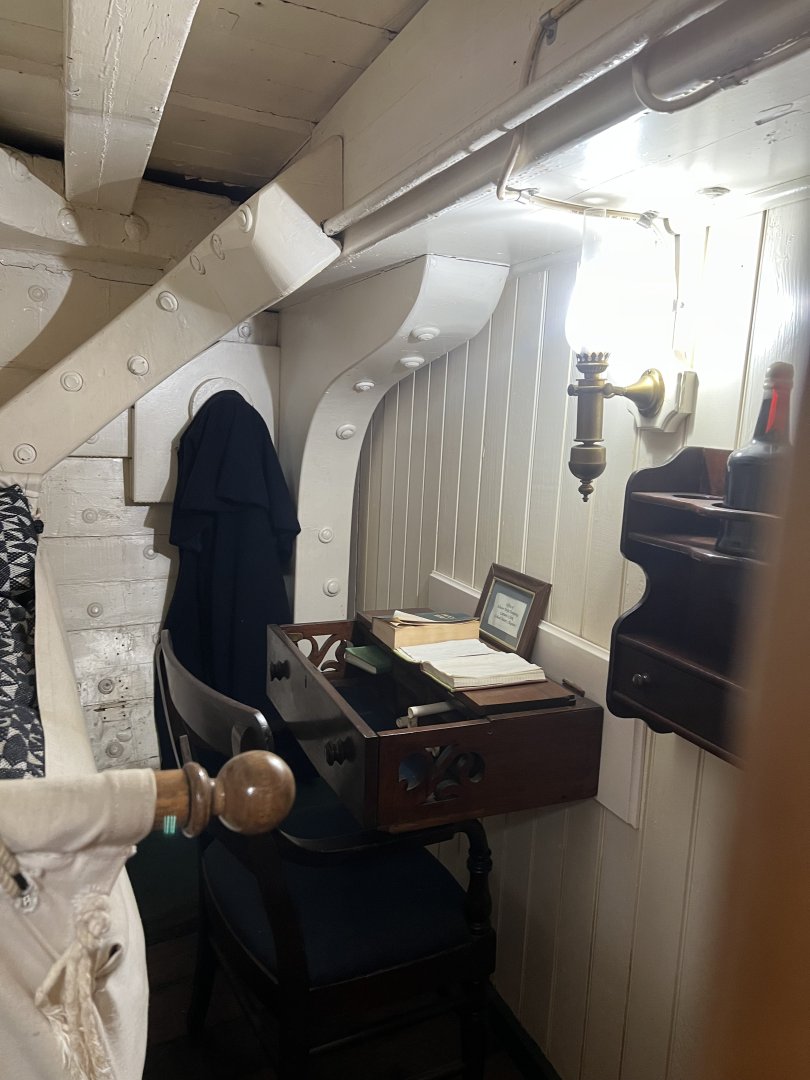
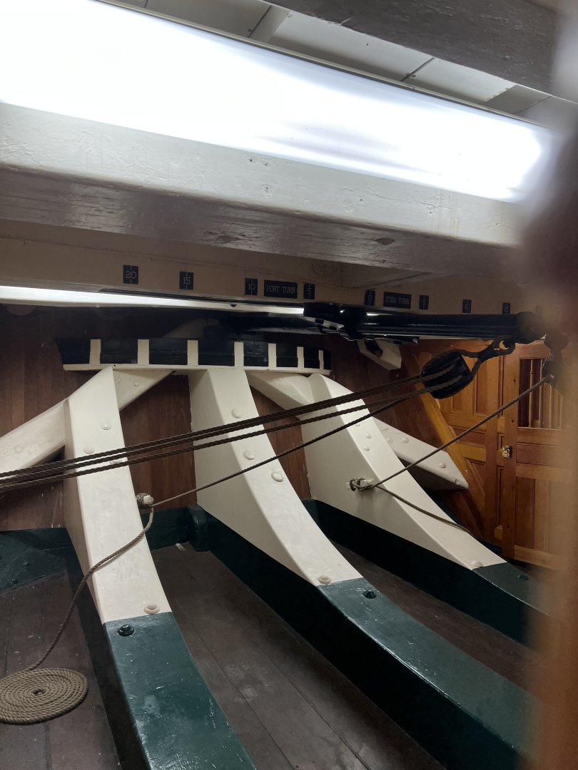
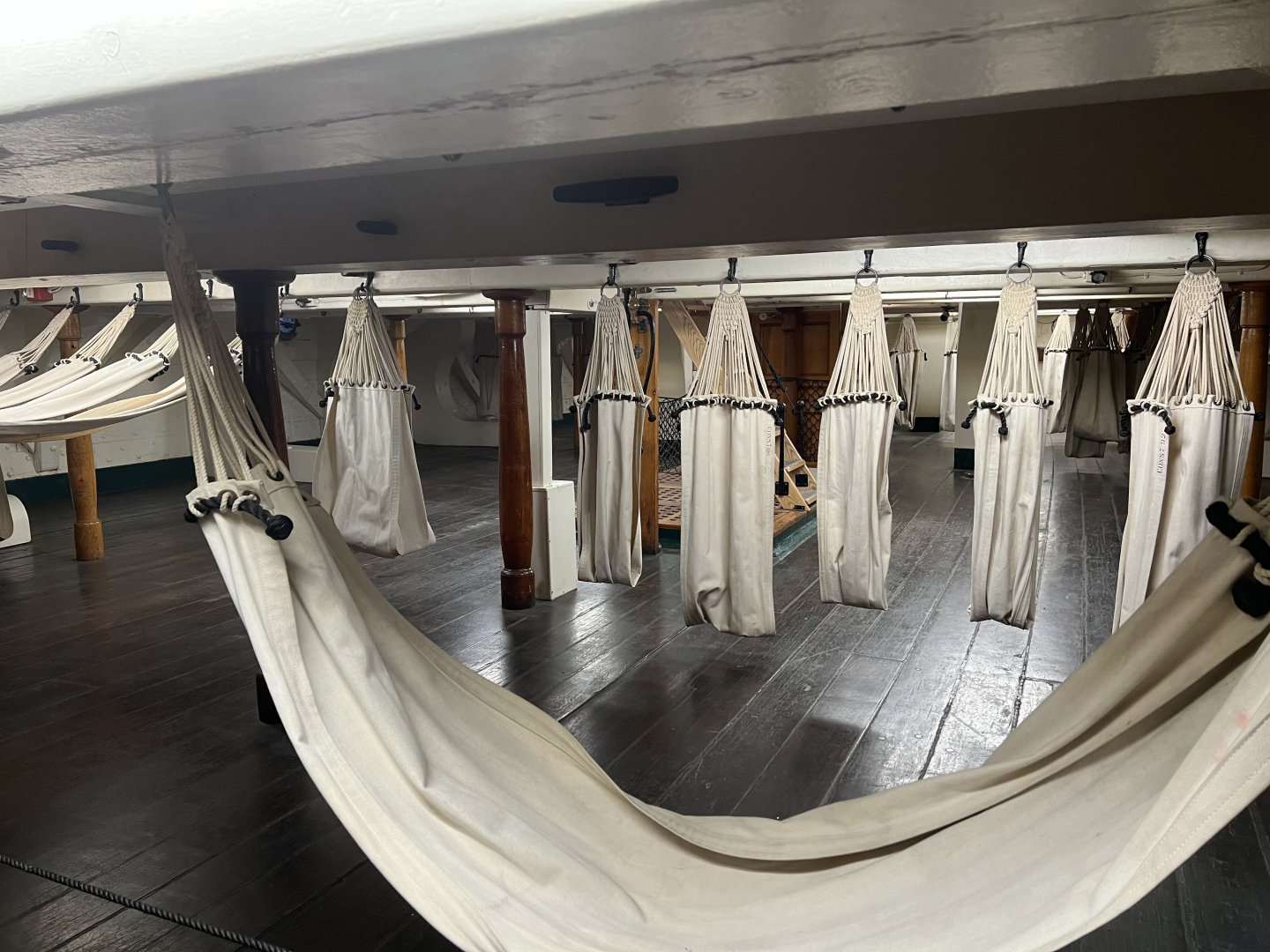
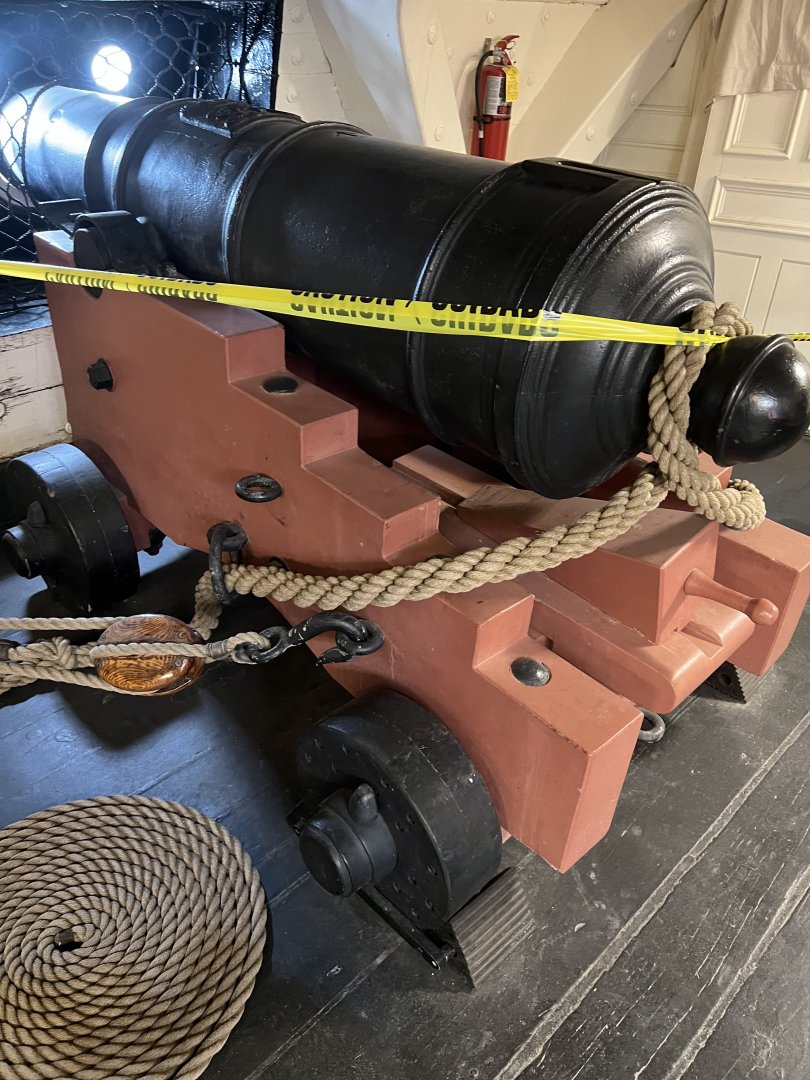
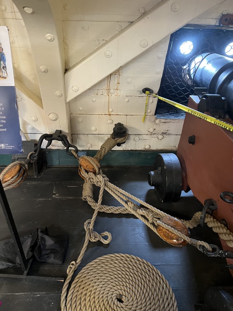
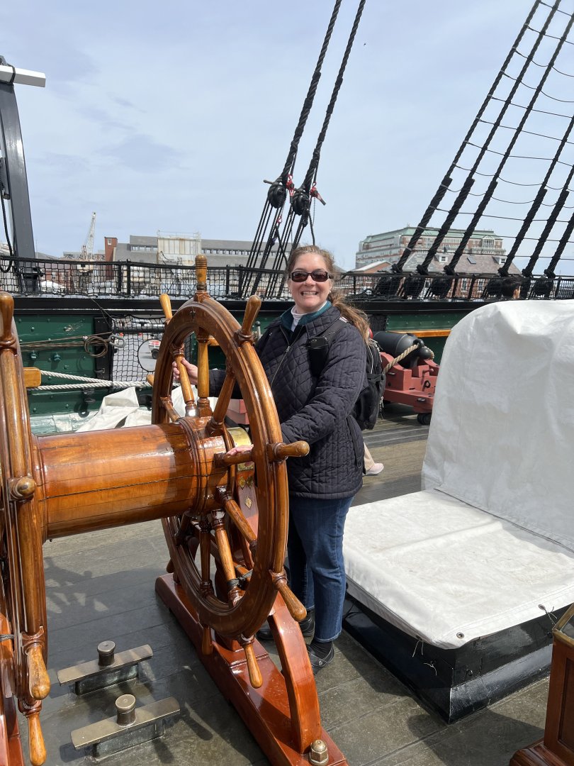
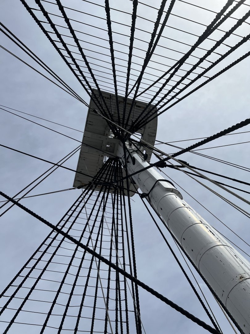
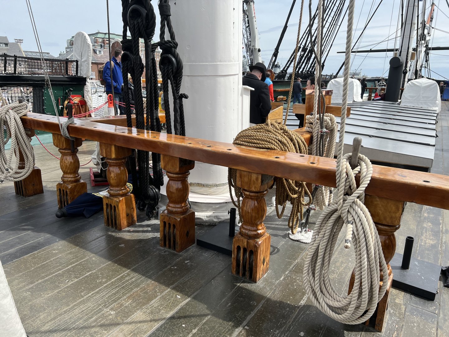
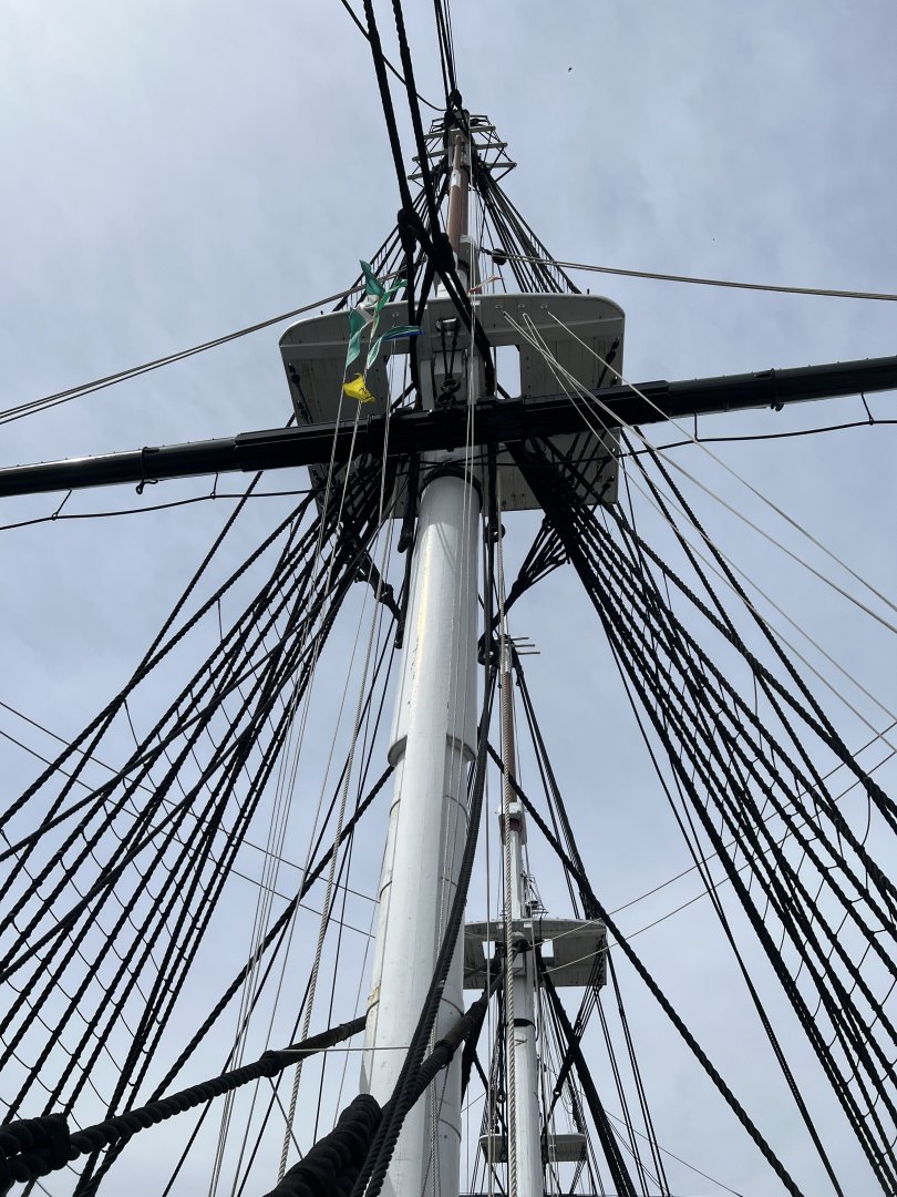
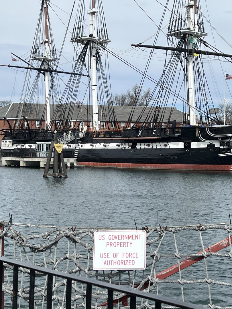
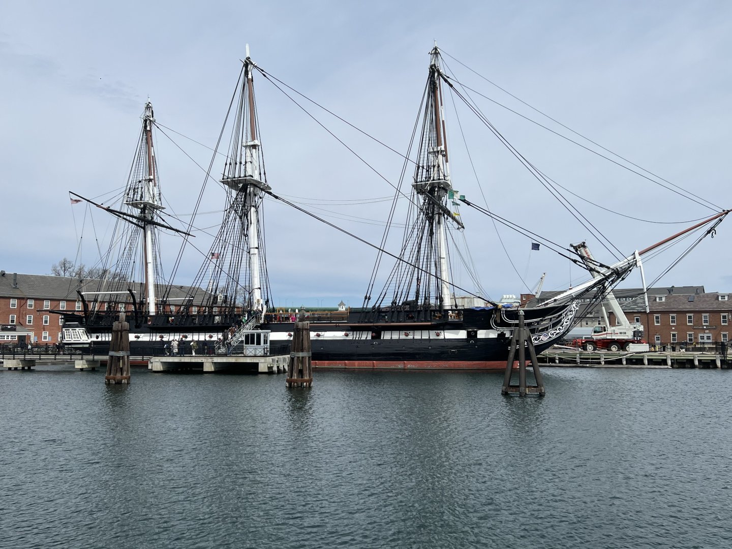
More pics from last year’s Easter Break trip - includes Mystic Seaport with the Charles Morgan and the USS Constitution. At Mystic - the shipwright allowed me into the large shed to view a mast he was working on - I believe it was for the Mayflower II. We had a great conversation about shipbuilding. Turns out he was from Paoli - a small suburb of Philly about 20 minutes from where I live. He was a Pharma executive who quit to become an apprentice shipwright at a New England school that specializes in that. He now does it full time. How cool! The Constitution visit was amazing. Such a feeling of history. Unfortunately the state rooms were closed for renovations - meaning a return trip will be planned soon! The Constitution is the only active duty US Warship to have sunk another ship (that the public is aware of). @JSGerson@GGibson@Der Alte Rentner


-
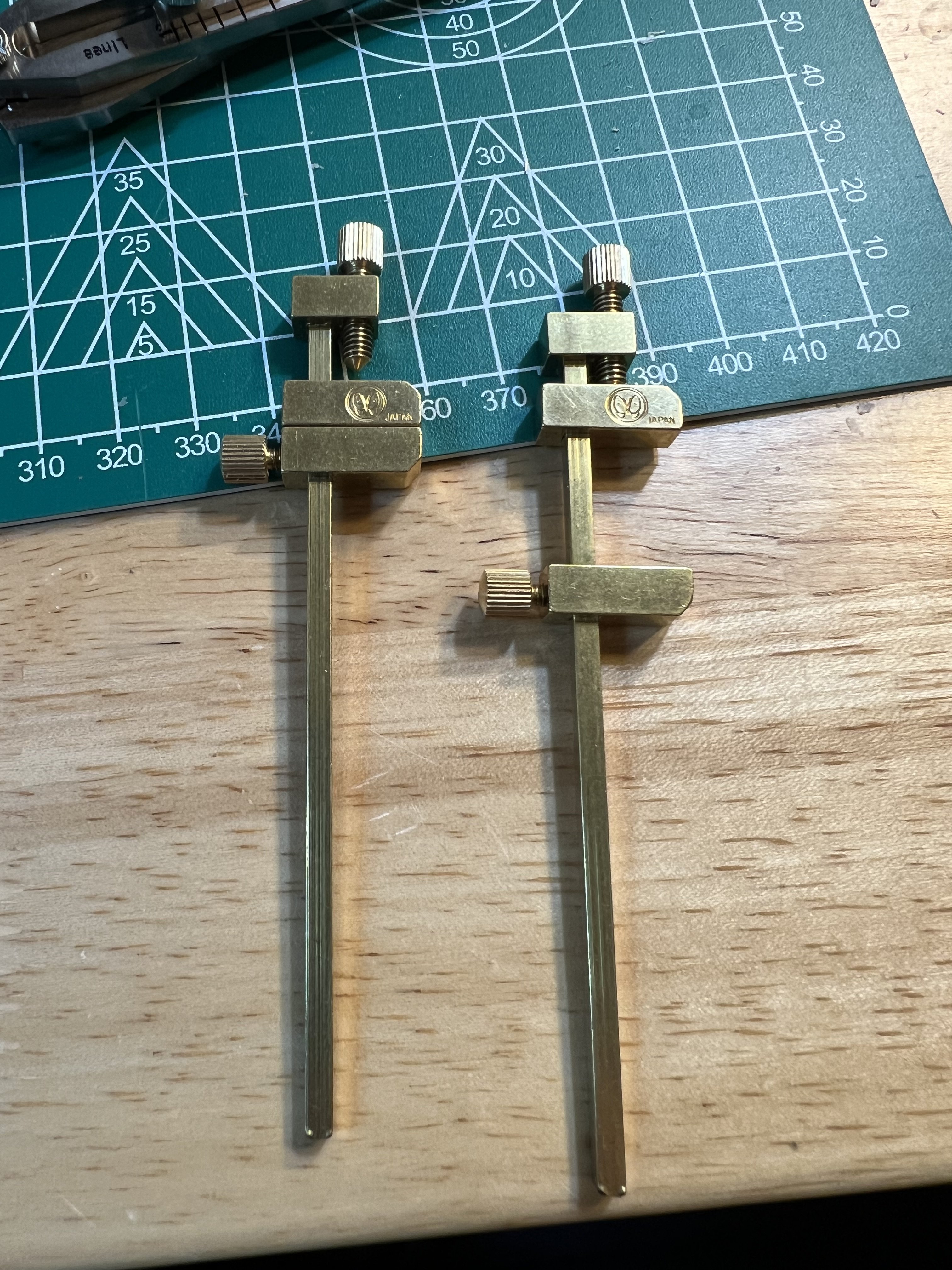
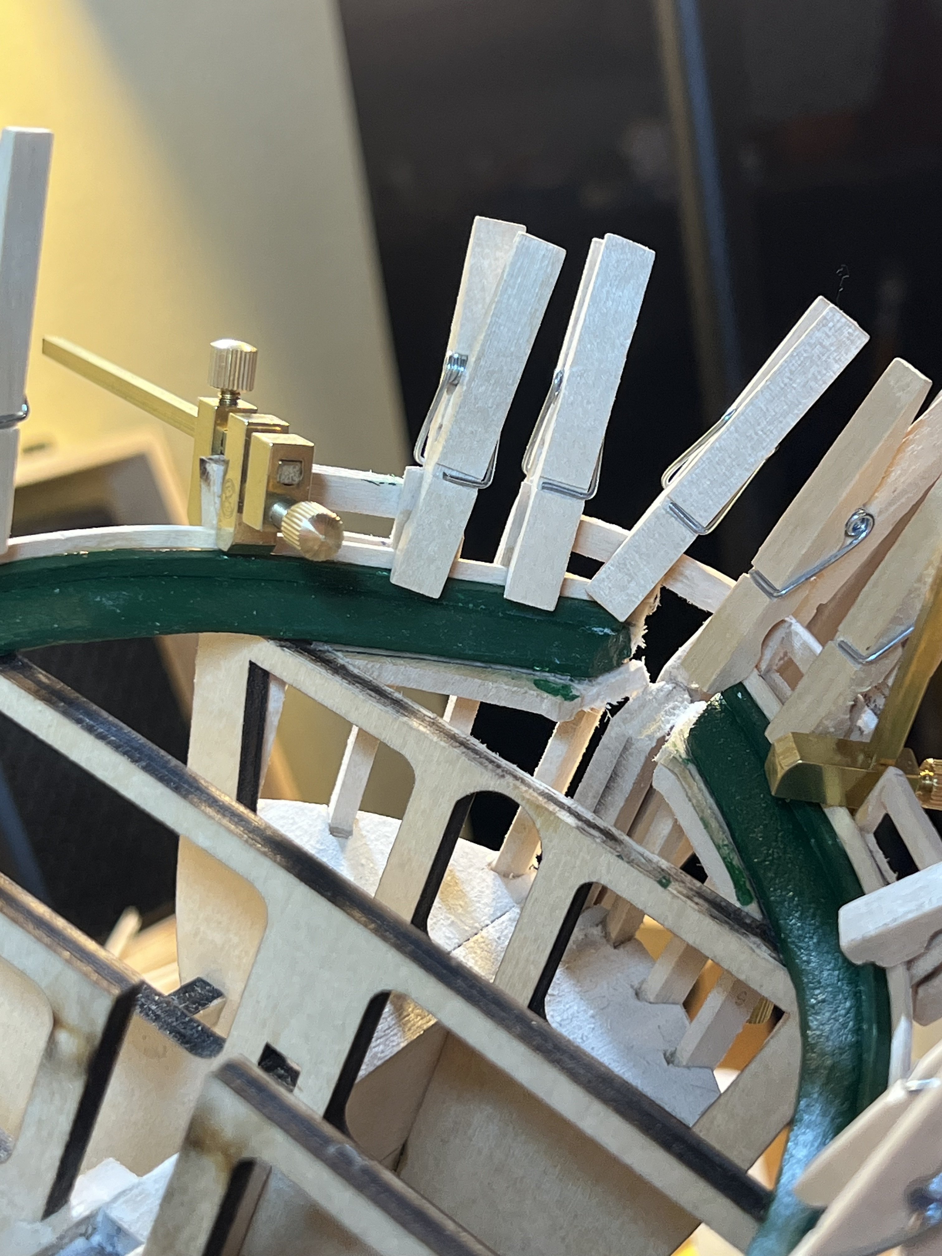
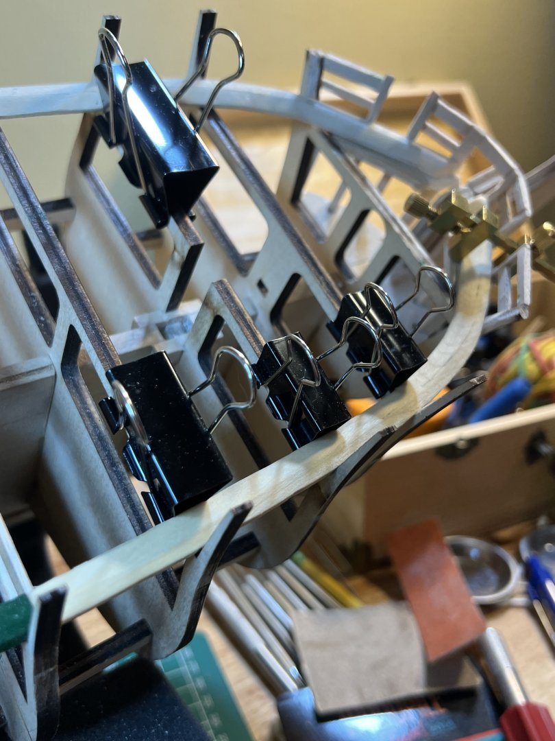
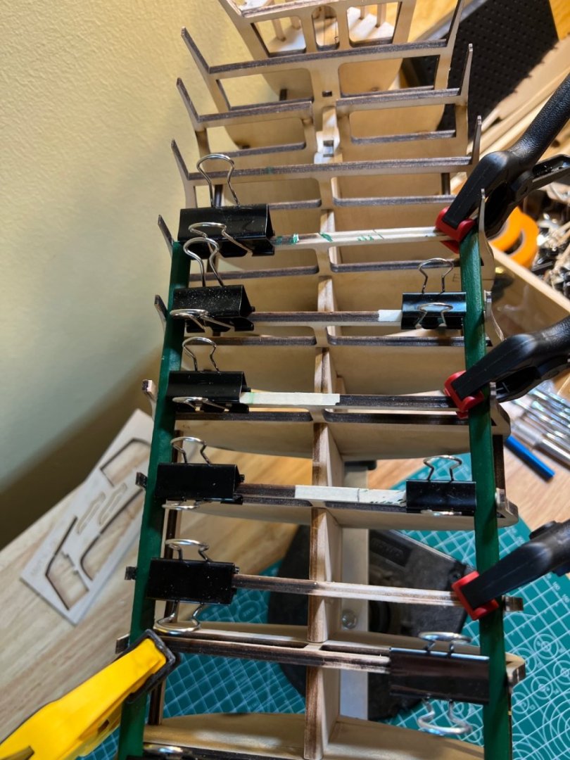
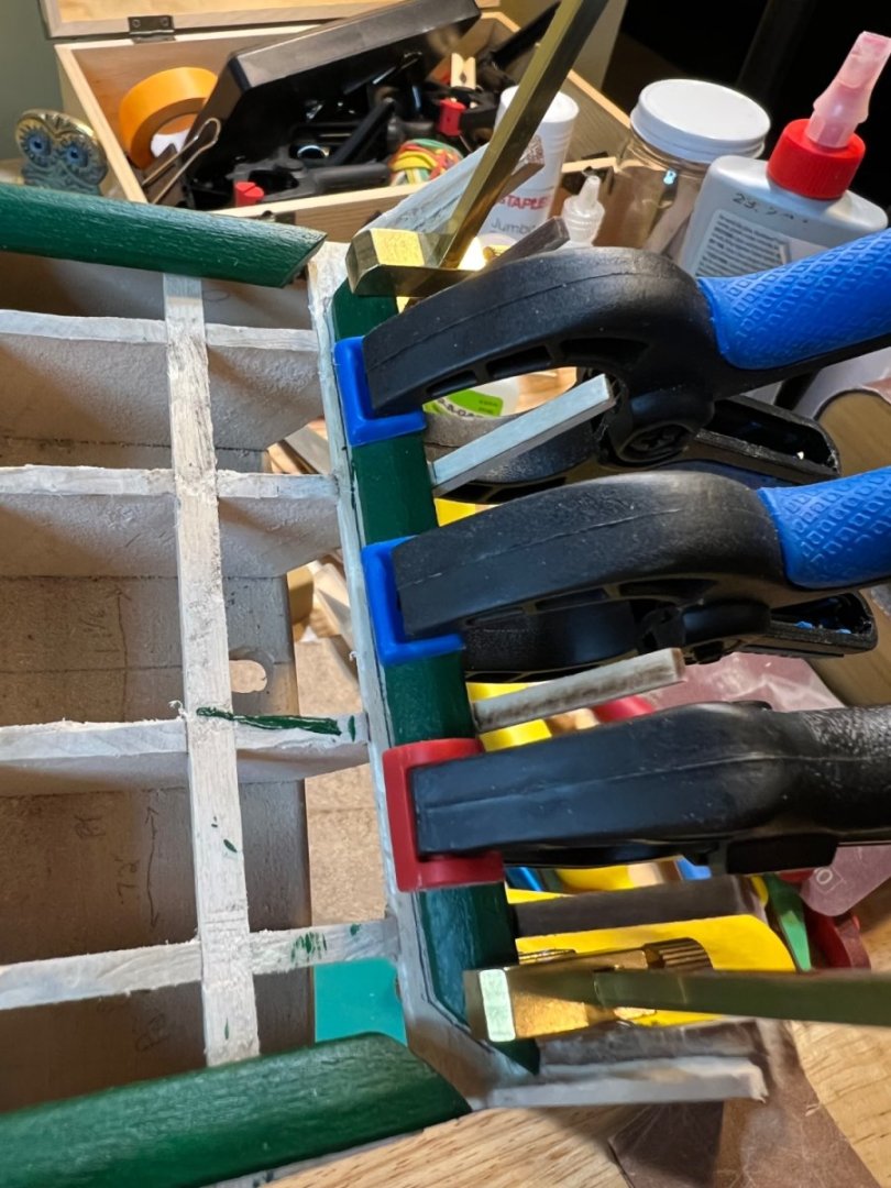
The clamps each weigh 3/4 of an Oz. They are very well made and are for delicate holds. The bottom slider determines the fit - top screws down to provide the clamp pressure. I don’t think they are meant to clamp a stubborn object. Question - for your bowsprit tenon - did you cut it out of the bowsprit? I was thinking of fitting a plug, shaping the angle and then gluing the plug to the Bowsprit. Seems easier but not sure how sturdy it would be. That tenon doesn’t look very sturdy either though.

-
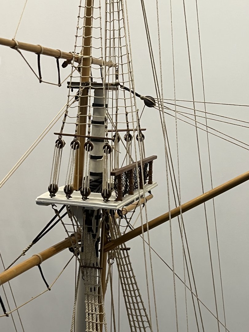
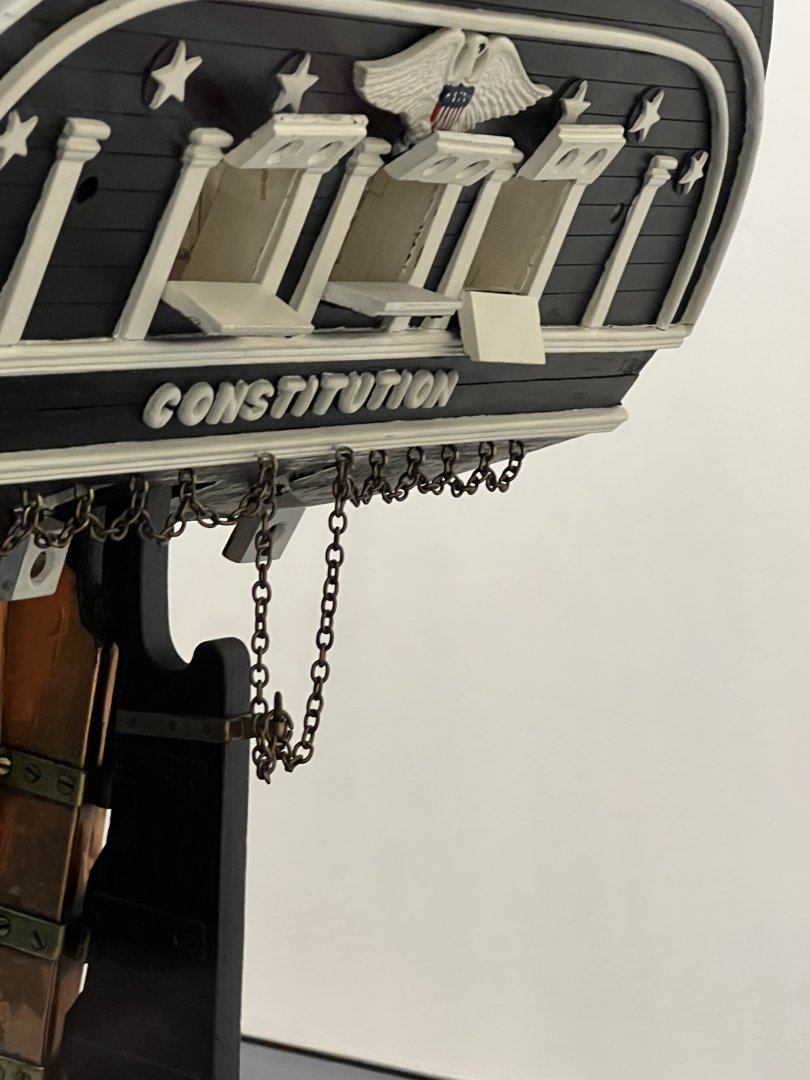
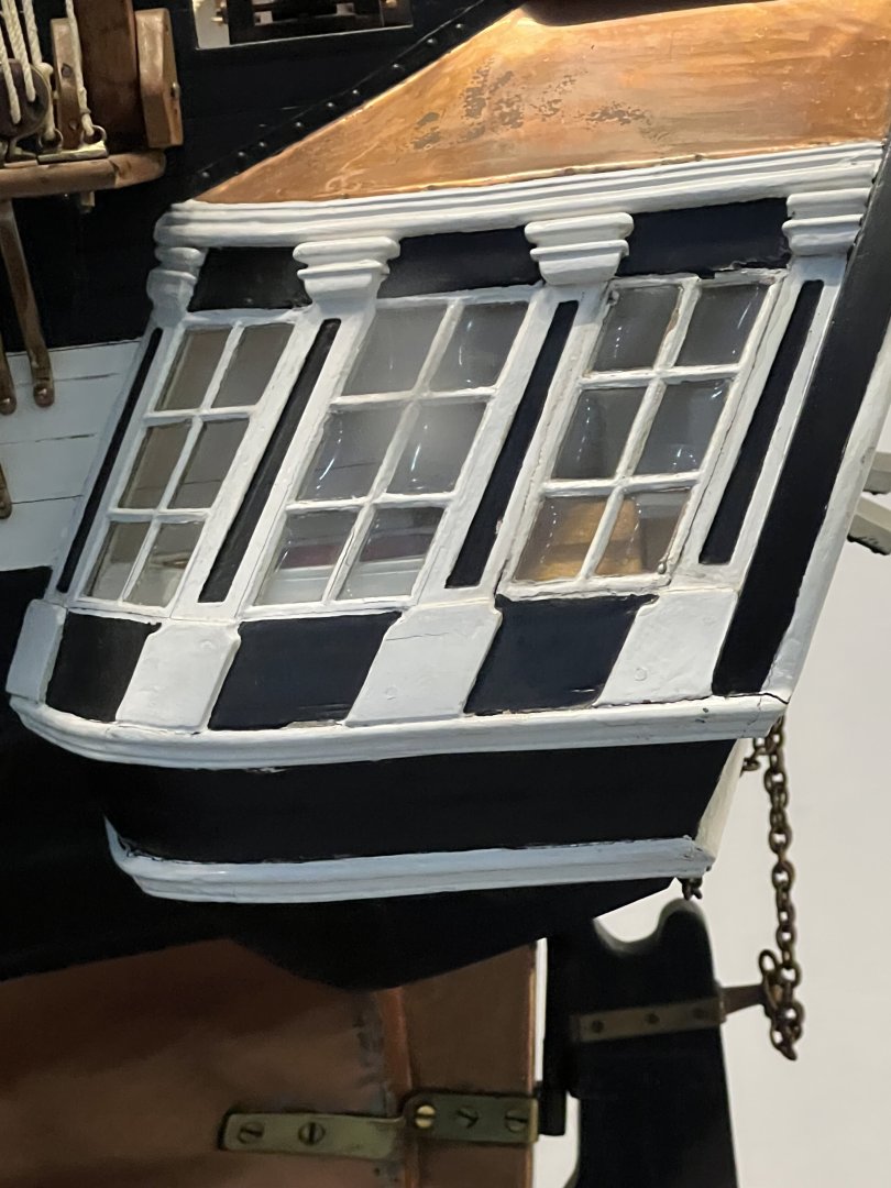
I don’t know the scale - but it’s the largest ship model I’ve ever seen. It’s in the video room of the Constitution museum. It’s much larger than the model at Annapolis. I liked the copper above the rear stateroom (you can see it in my pic)- but that’s not on the current ship. You can find some great Constitution modeler resources at USSConstitutionmuseum.org/discover-learn/modeler-resources/ Plans galore.
-
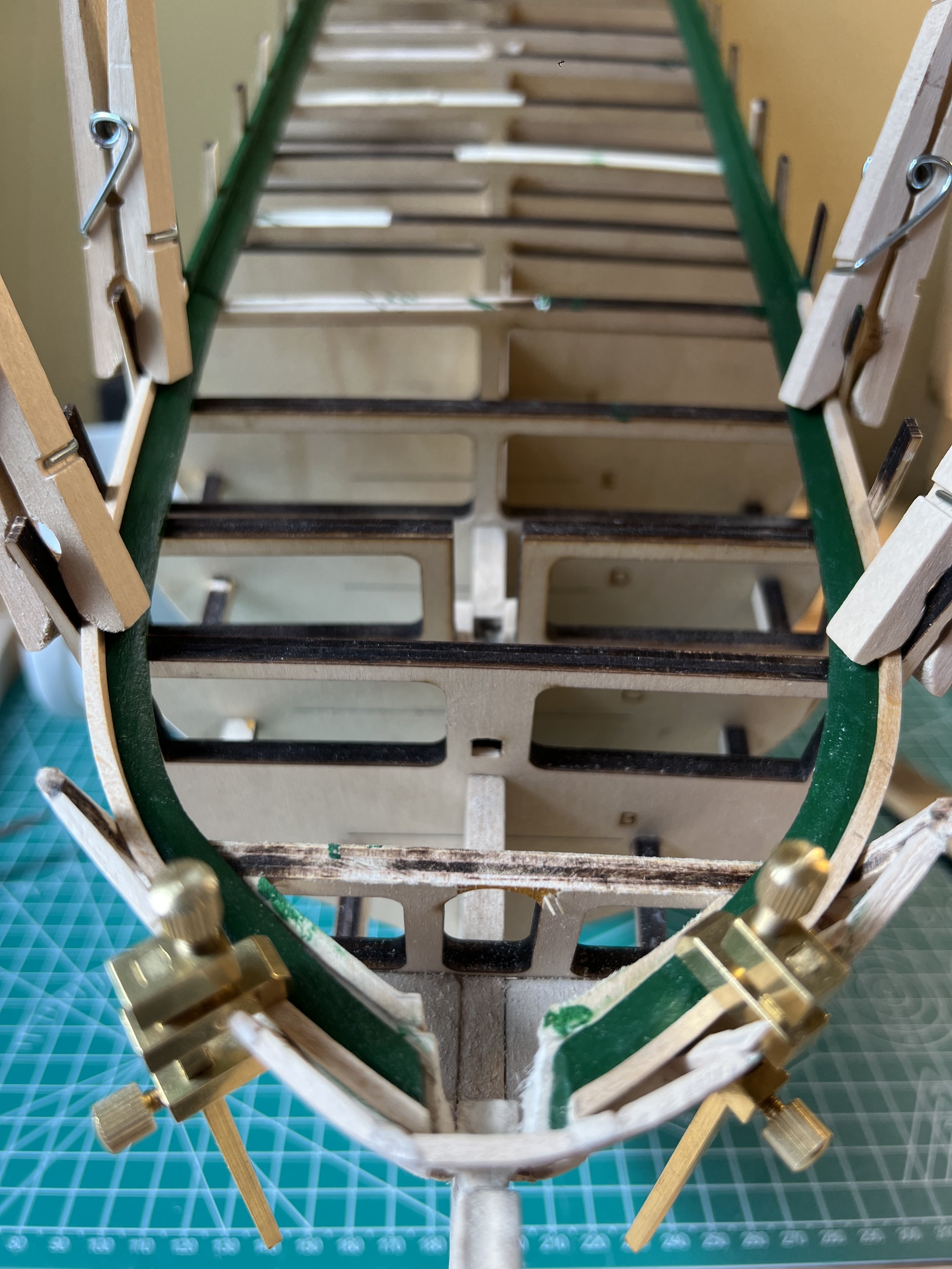
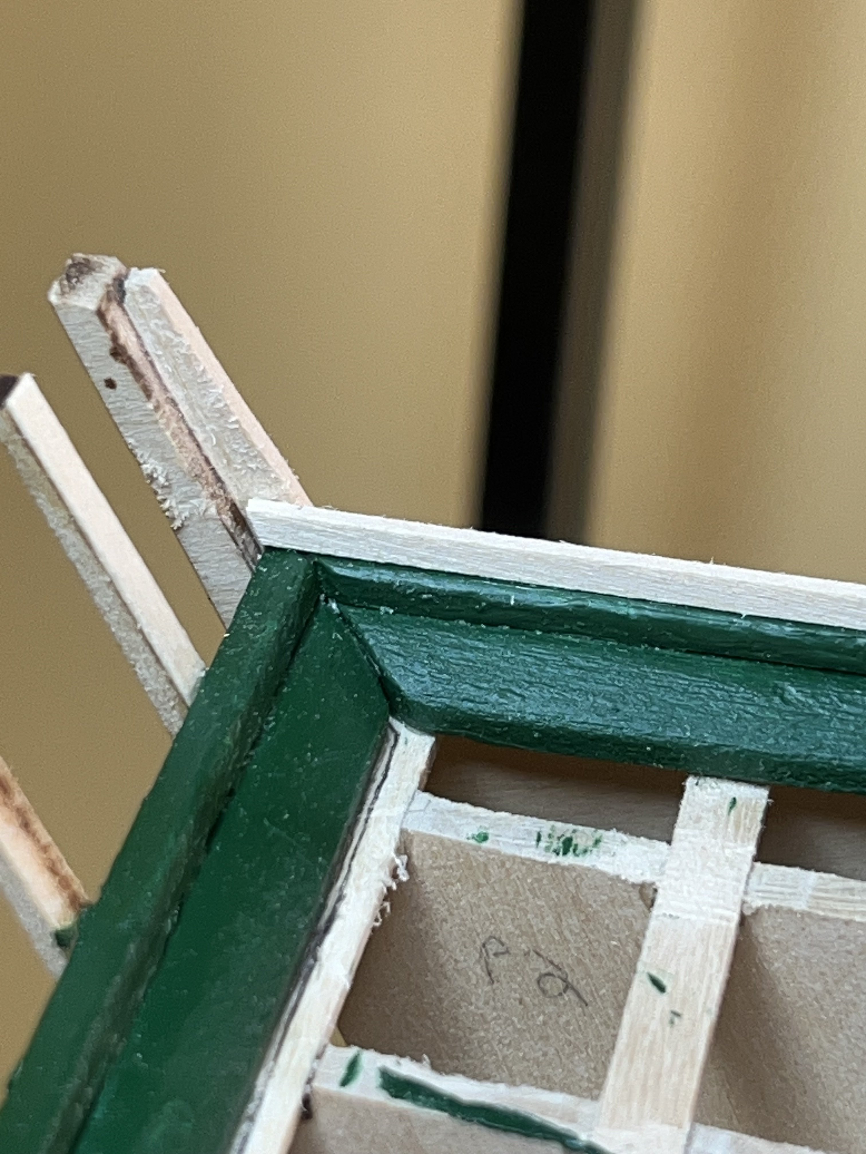
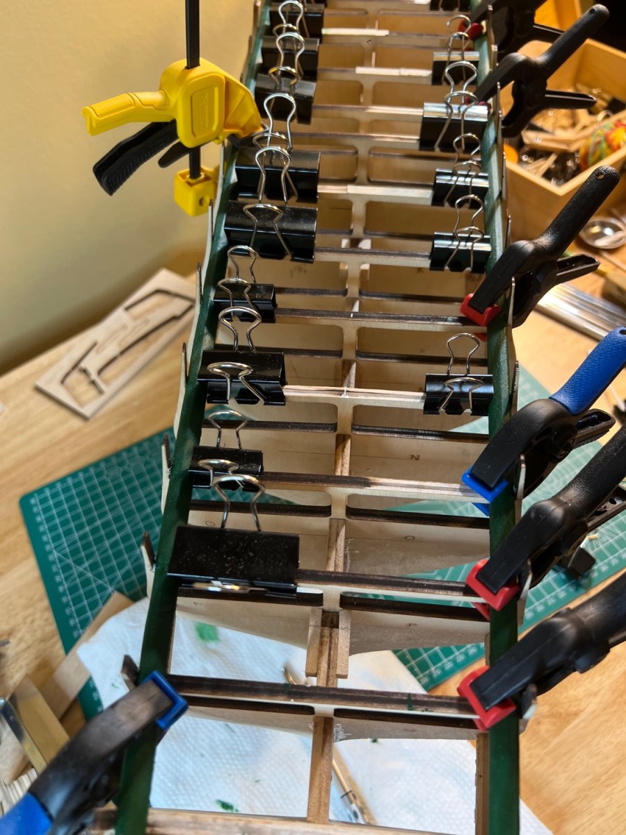
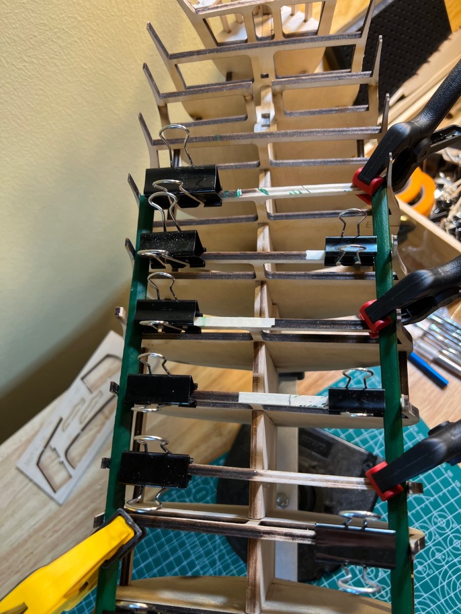
The Waterway and inner Planksheer are done. They were not very difficult from a technical standpoint (simple angles and shaping) - but they required a lot of patience. The shaping was good enough that I was able to use wood glue. Additional faring of the upper bulwarks was needed. I’ve now begun the inner bulwarks planking. The plank strips require some fine finishing with 400 grit sandpaper. Lots of measuring, cutting, gluing and clamping. The planks at the bow require some shaping and a touch of CA.


-
Peter - No tenon yet! I’m just getting to that section in 2.5.1 (after bulwarks planking). I’m sure the tenon will be a better/stronger solution than a separate block which I’ve considered.
-
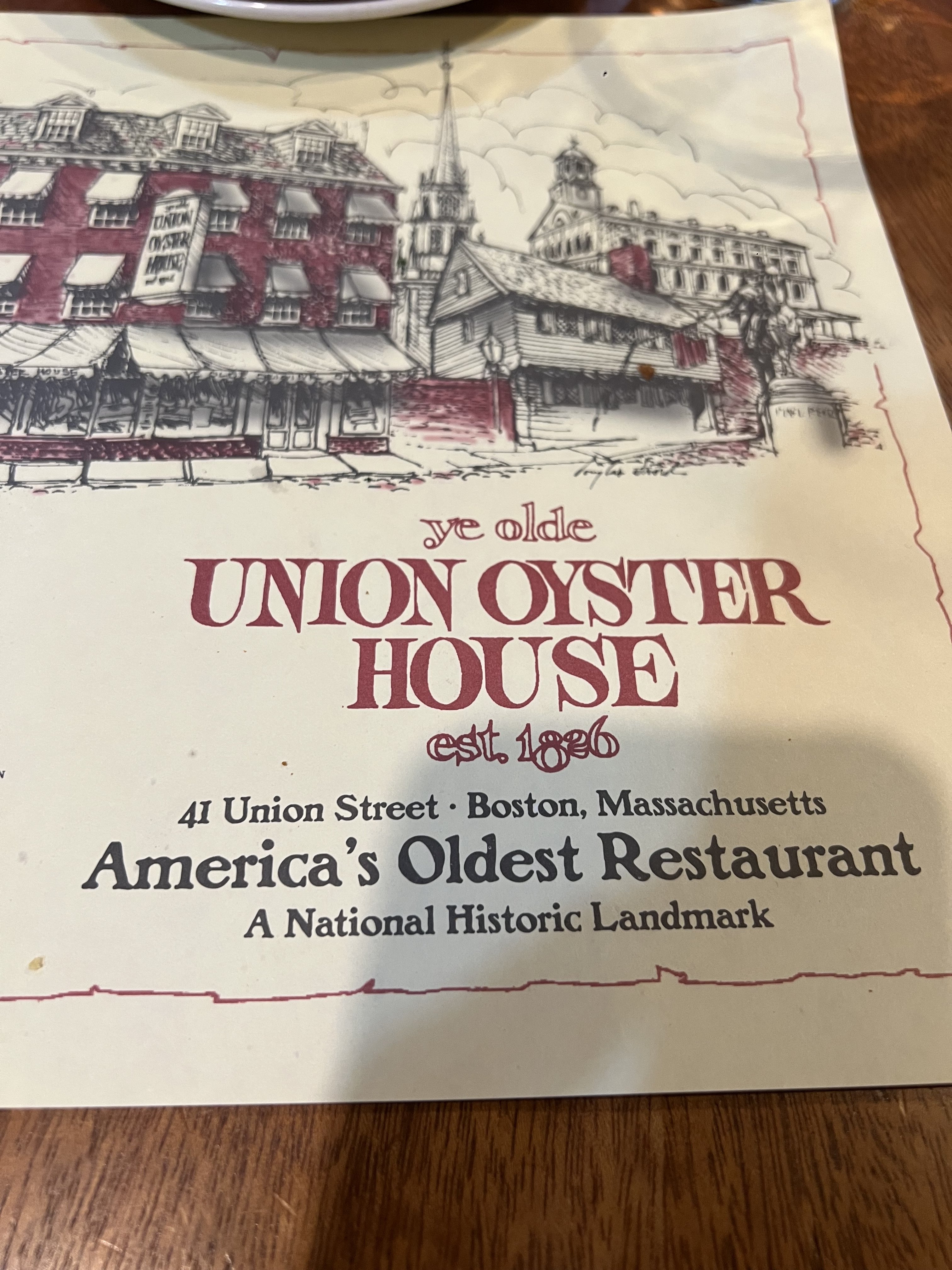
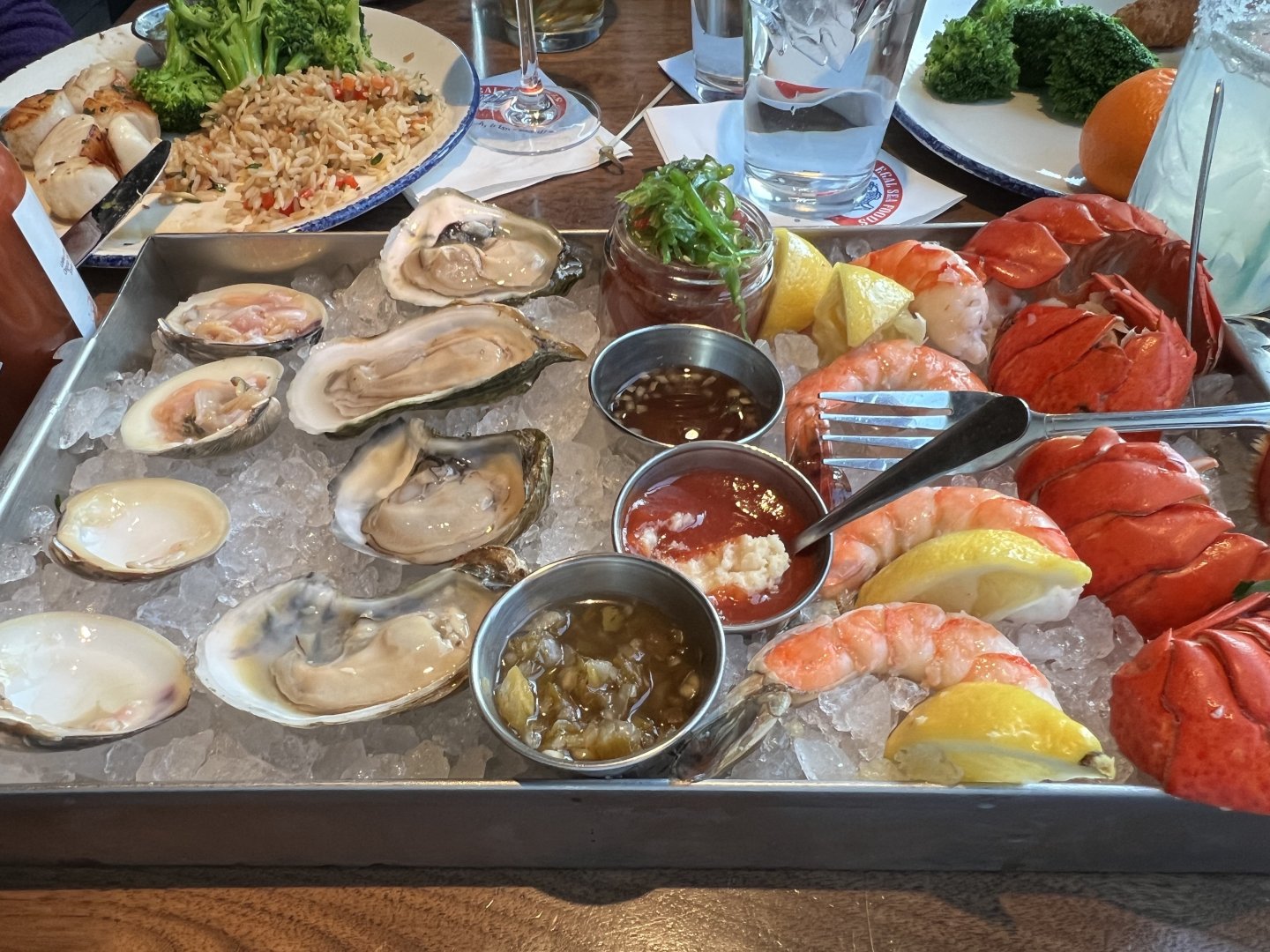
Catching up on a few comments. Jon and Gregg - I’m happy that you liked my pictures from my Constitution visit last year. We visited Mystic Seaport, then Boston and did an abbreviated Freedom Trail walk. I have a lot of pictures but they almost all have my family posing. At the time I hadn’t started the model yet and unfortunately, didn’t take any pics with that in mind. I’ll try to find more to post. Jon - yes - I’m a foodie! I took that picture in the kitchen since I was painting (near the sink). I’m have a few Bistro Fillets in the fridge I’m going to cook up for my girls tonight 🙂 I found some pictures I took of a very large Constitution model on display at the visitors center. I’ll post others when I can sort through them.


-
Thoughts on painting. I never contemplated leaving Connie au natural. We all love this hobby for different reasons. Mine is not to showcase my skills (perhaps b/c they are novice), rather - to present a beautiful representation of history into my house that spurs conversation on the subject matter that I chose to spend so many hours upon. I was proud of my 1st time planking my only other model, the Swift. But b/c my planking results were uniform (after hours of sanding!), after painting- it was hard to tell it was an individually planked model. People who understand quality and detail, notice the planking upon close inspection. Others dont - but they would never appreciate the effort anyway. So I paint. Now - traditional or air (spray)? I’m constantly humbled in this forum by the skill and historical accuracy & interest attempted by my fellow modelers. Some folks present copies of original period plans of lower deck details. After hours of analysis, planning and execution- they then spray paint their ship. This I don’t understand. I mean absolutely NO disrespect - but after many hours expended in making a model historically accurate - why spray paint? I’ve been on the USS Constitution - and the thick layers of uneven paint give it an historical feeling of age, time, history and wonder. Like an old home’s wooden window sills. I’ve added some pics of a recent trip - (painting was not my focus). Anyone who has visited the Connie, or any other historical ship - will understand the feeling that layers of paint convey a sense of history. In my personally humble opinion- the difference between painting and spray painting an historical ship model is like the diff between the old Star Wars Movies that utilized actual models, and the newer movies with CGI. If you care - you will notice.


-
Thanks for looking that up - truth-be-told, I had already checked your log 🙂 I’m leaning on cutting out the tab - it seems like it was an another laser cut mistake. Are you still going with the au natural Conny?
-
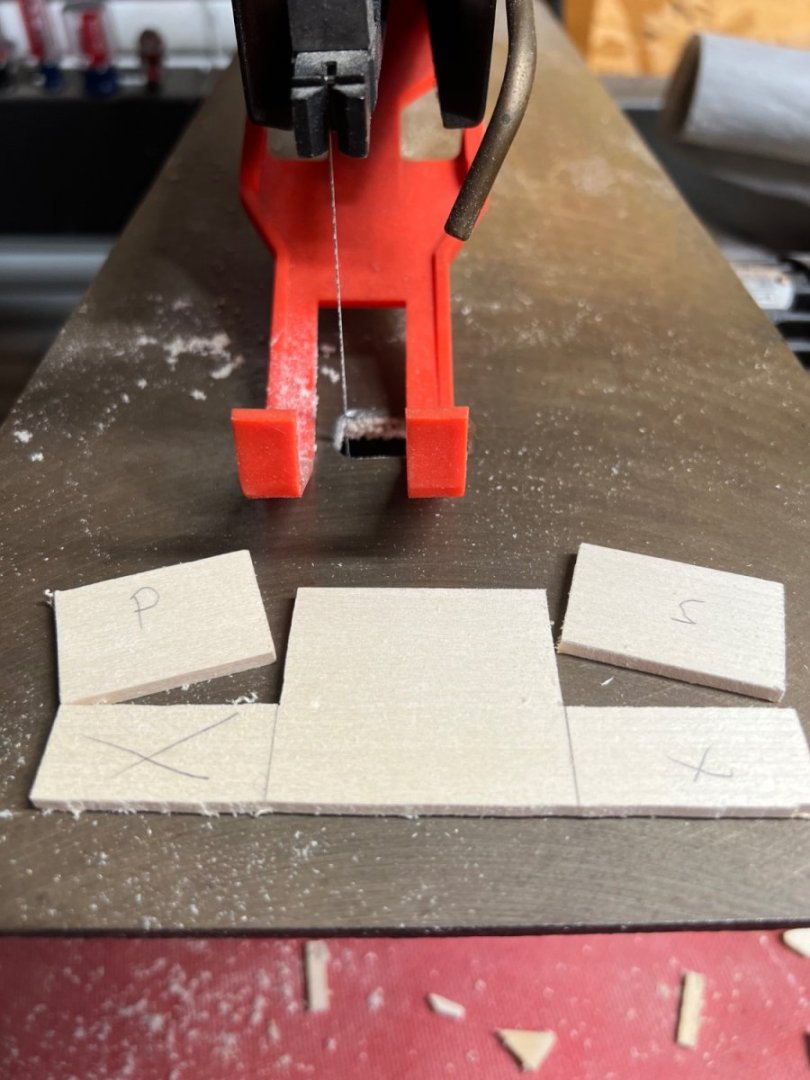
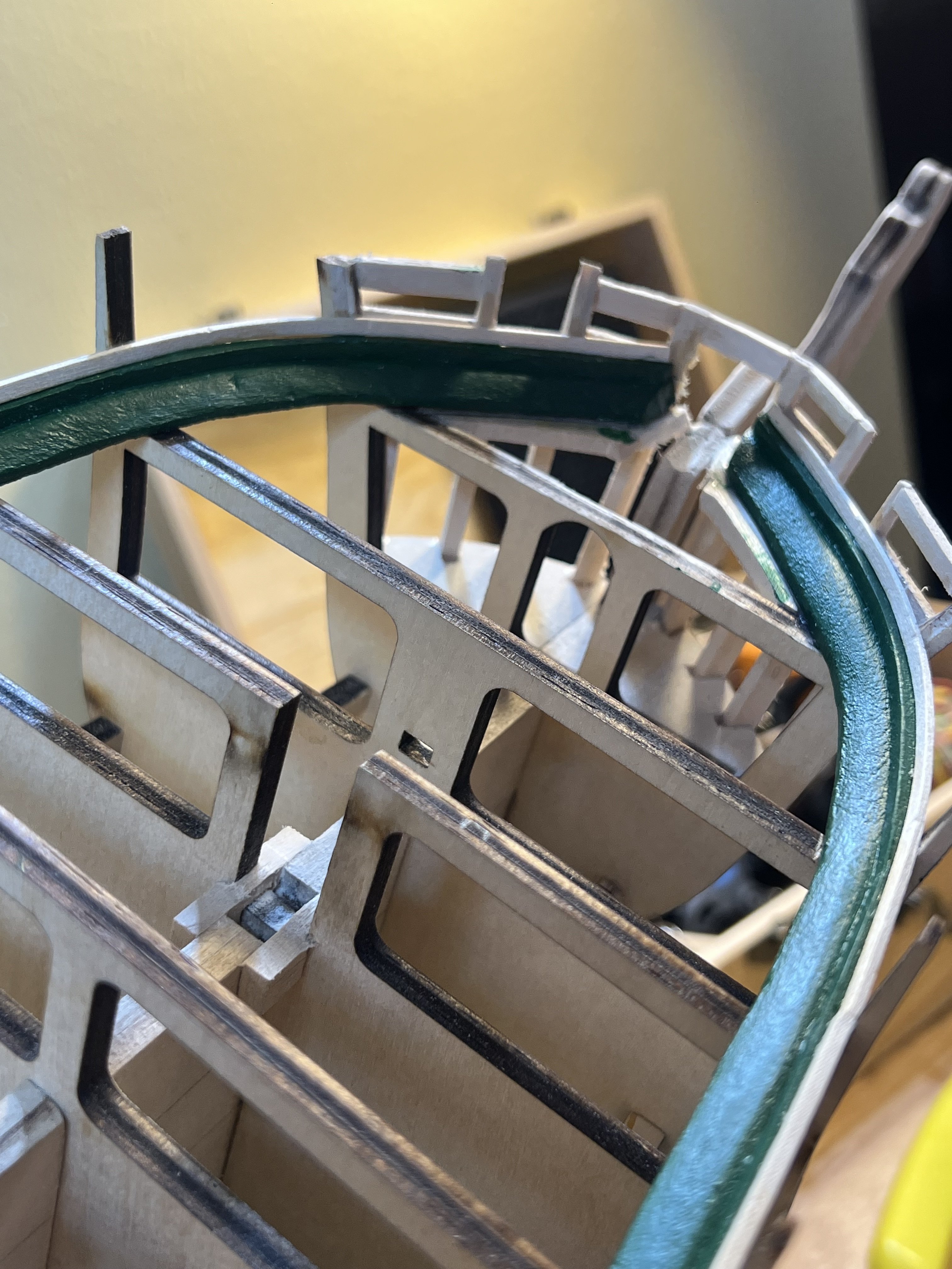
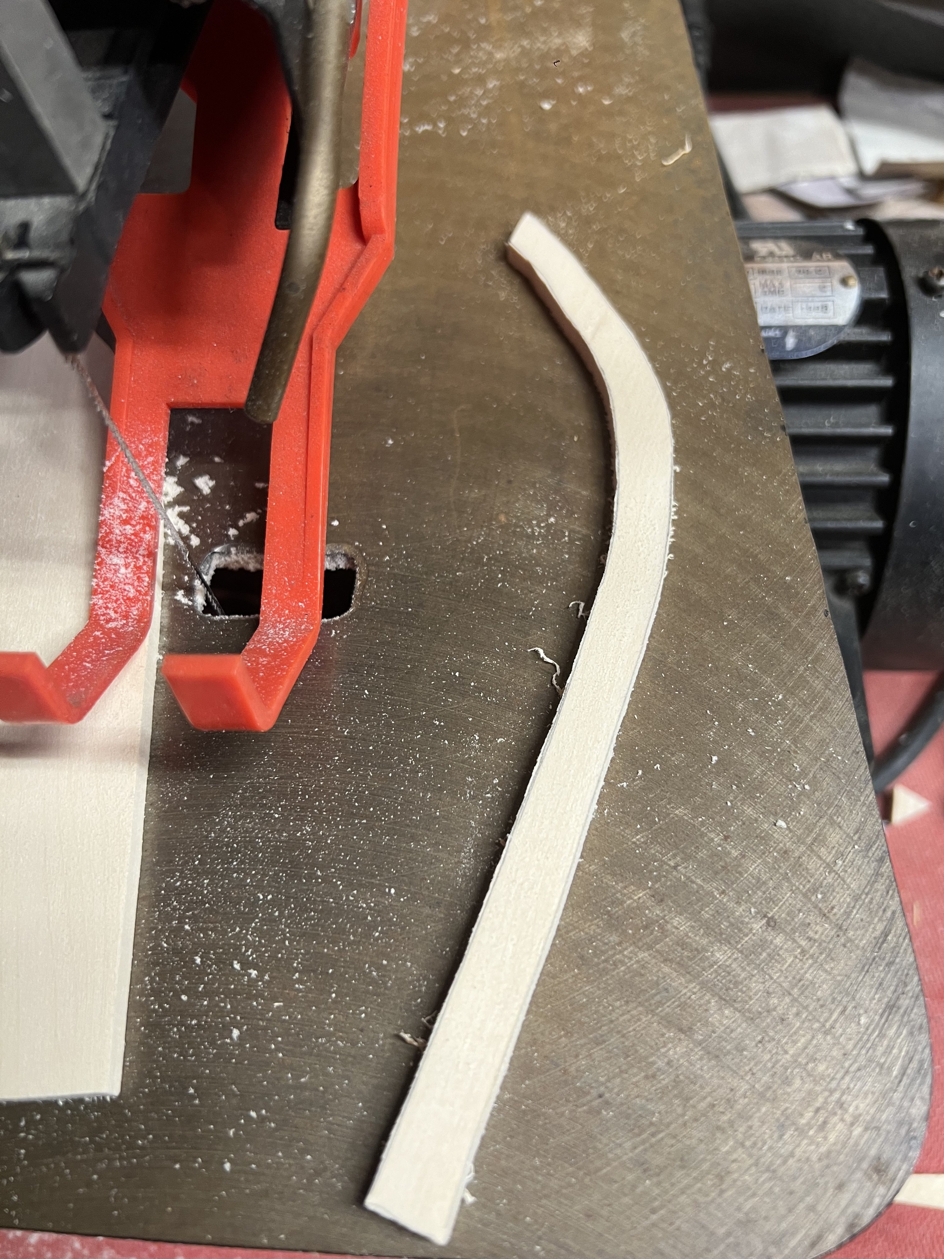
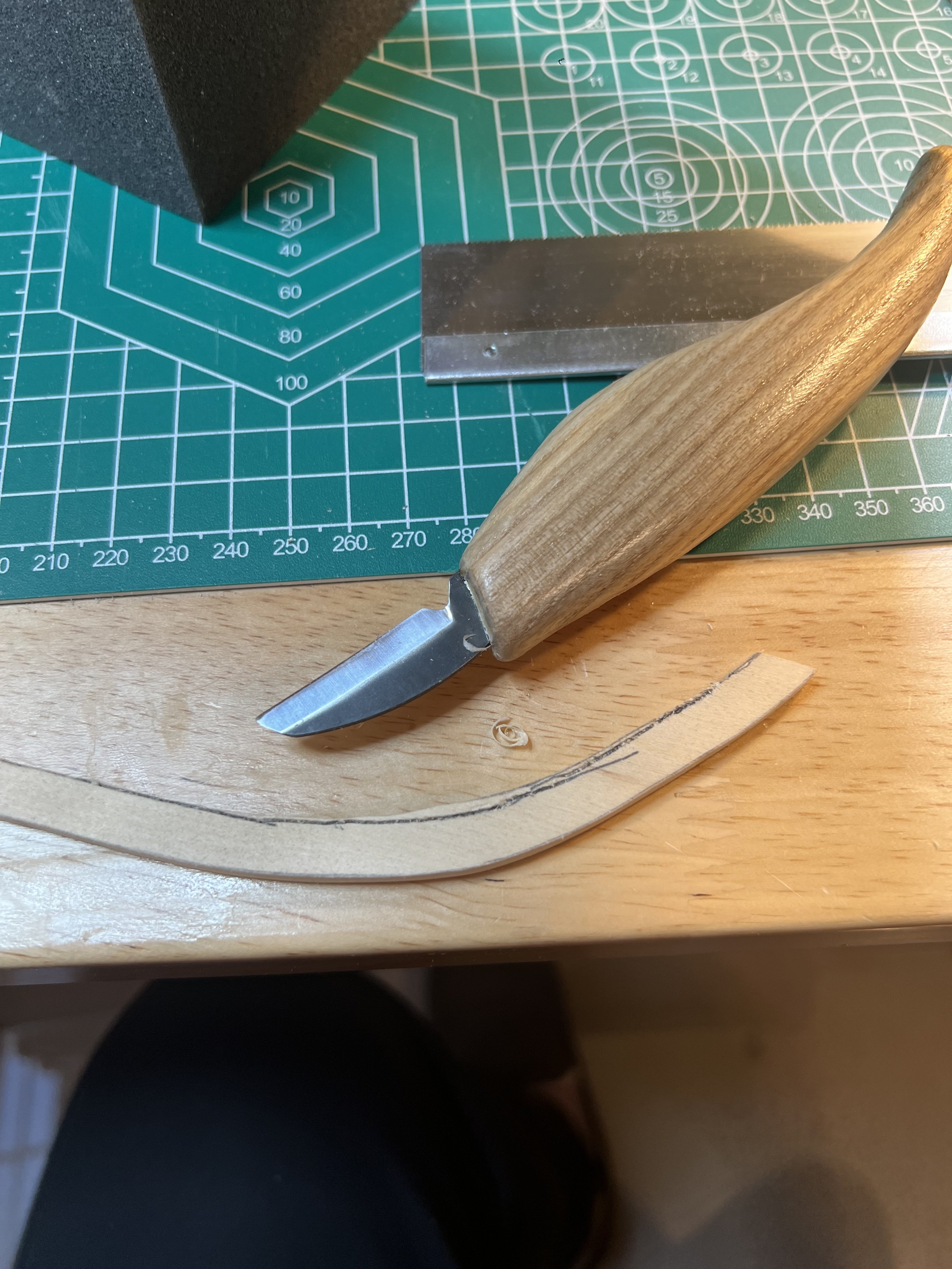
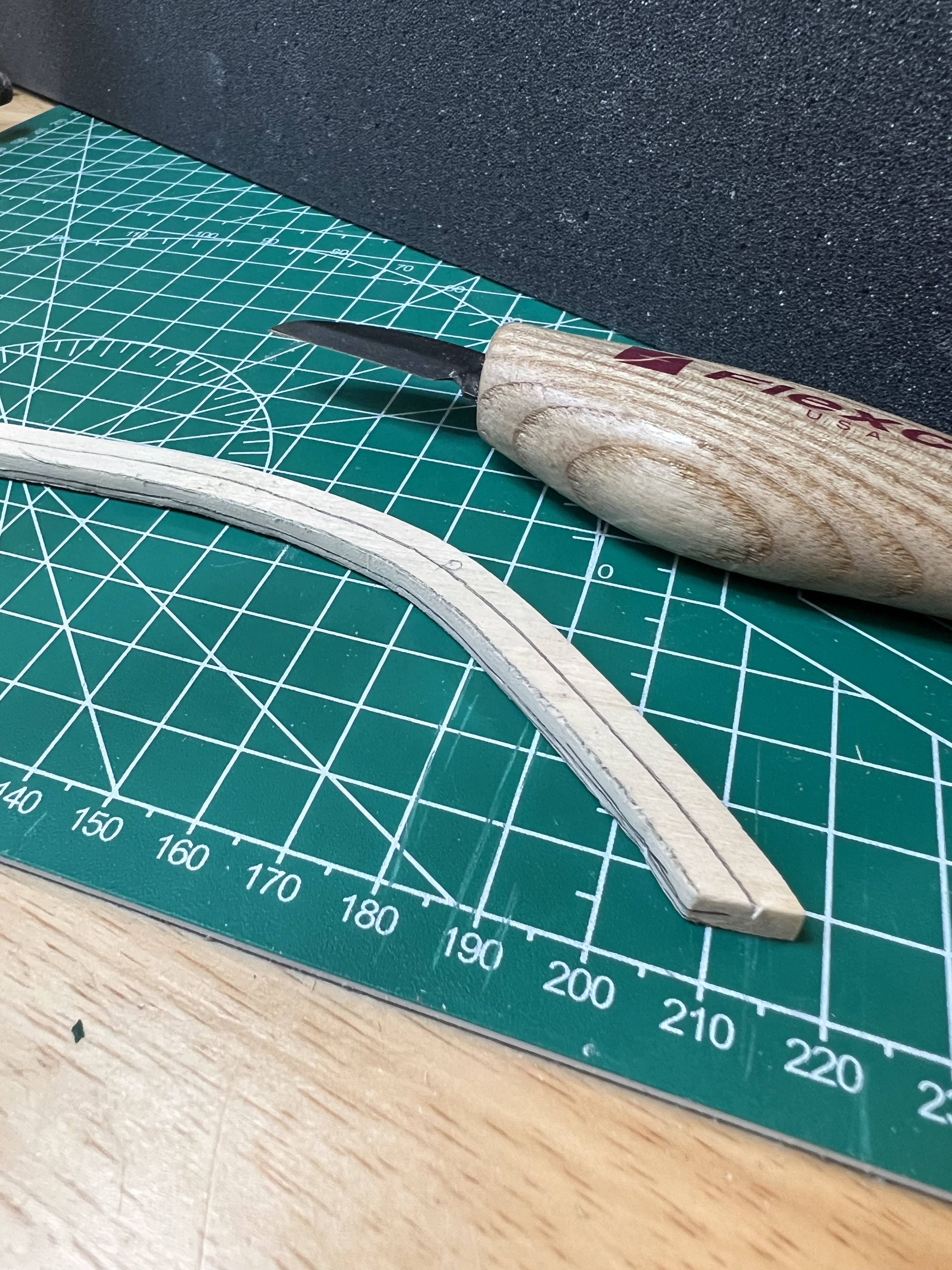
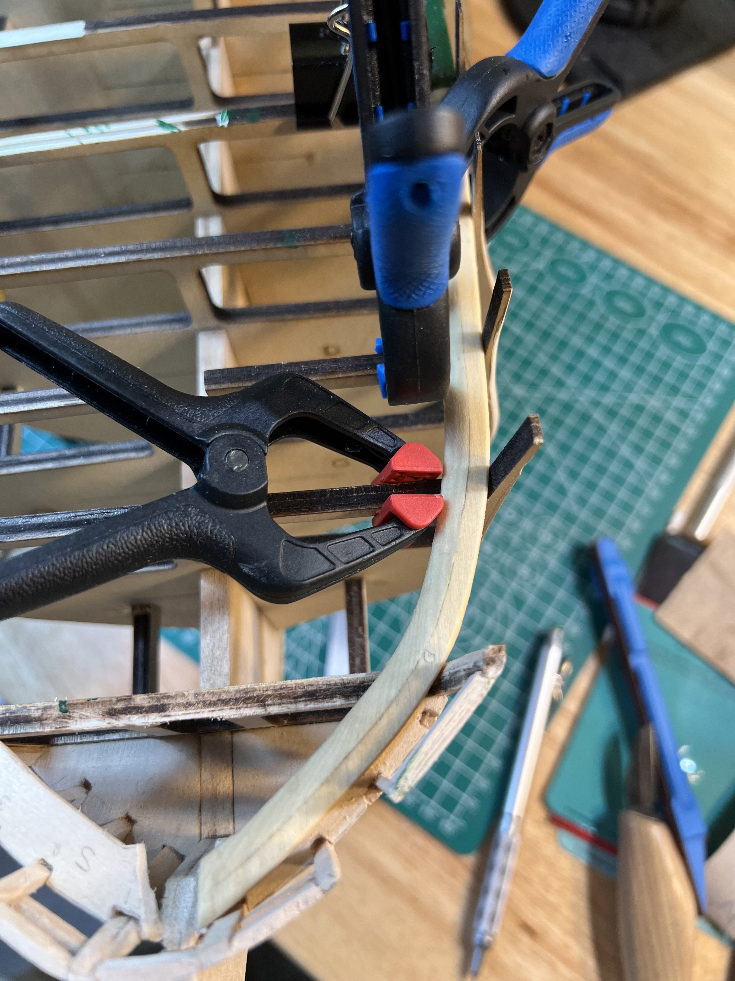
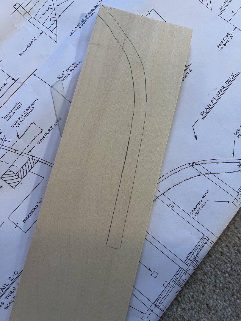
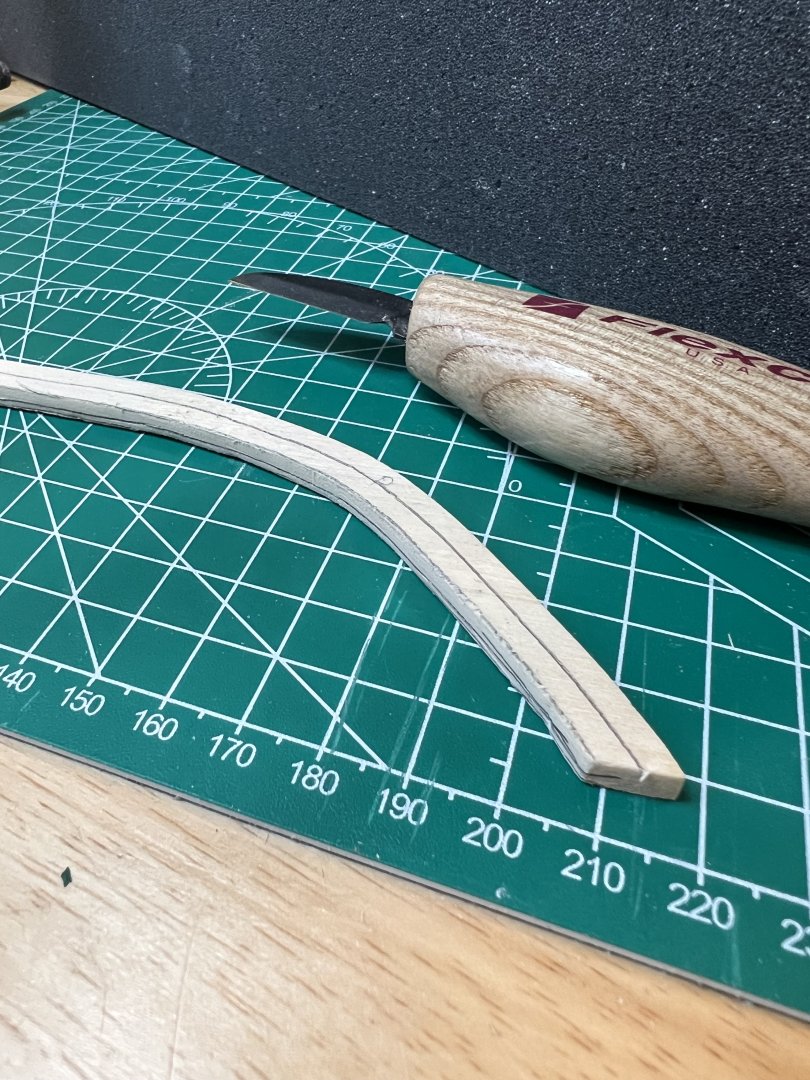
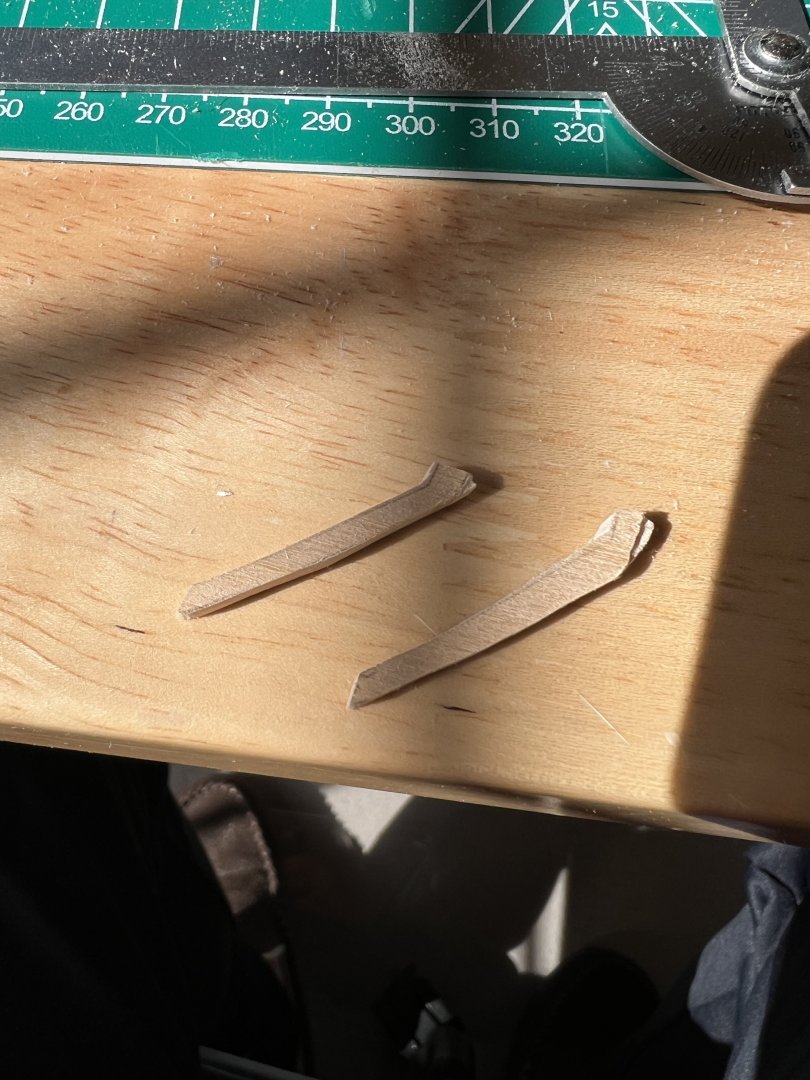
The port bow waterway was somewhat straightforward. I used the plans to create a template. Then cut the waterway on the Scrollsaw, finishing with blades and sanding. The outer bevel curve took some patience with the hand tools. I applied my usual methods - measure, refine bevel, heat, bend, clamp, repeat. I found that with the wood I’m using (hobby store basswood), bends easily, but it takes an overnight with clamps to finally set. I noticed that I had been too aggressive cutting my Knighthead “platform” (the bow waterway rest on it) - such that after affixing the waterway, no purchase would remain for the foremost deck planks. Better to address this now. I used my prior platform template to create the outside curve and whipped up 2 crude extenders on the scroll saw. I also needed to extend 2 of my bow “timbers”. I never had much faith in those - I’m sure I’ll have to do the same when I work on the starboard side waterway.


-
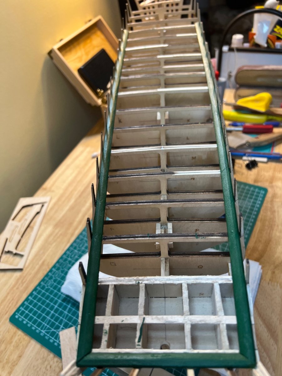
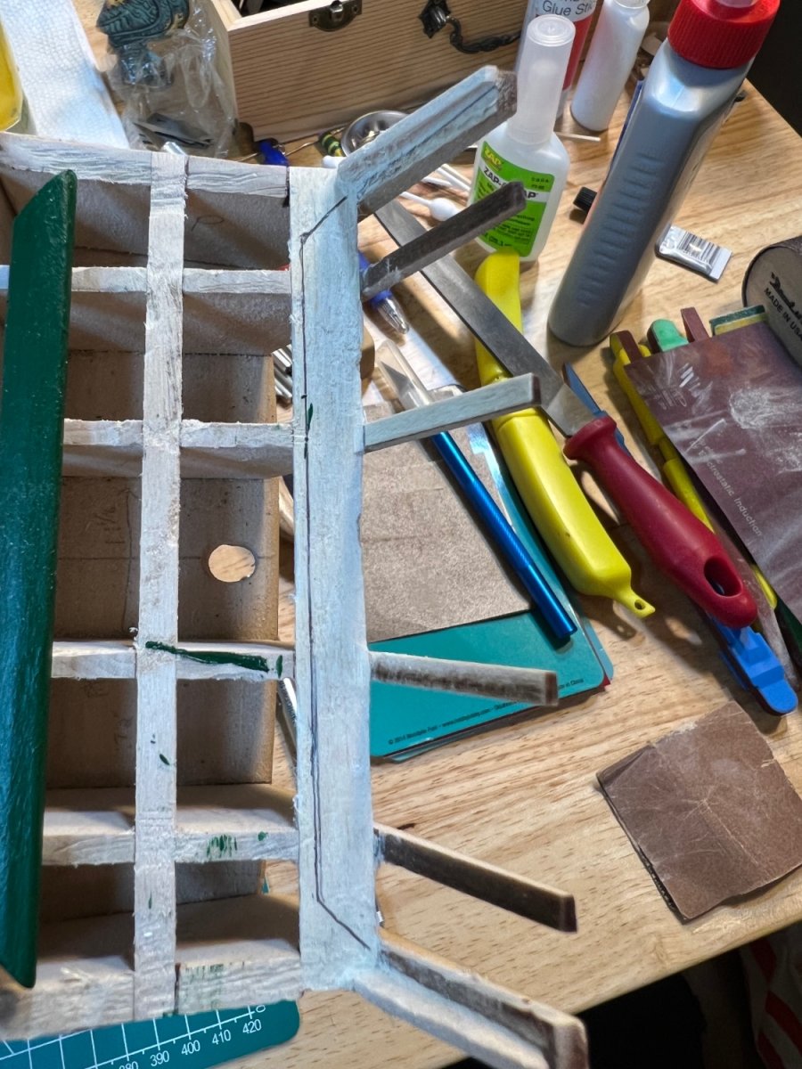
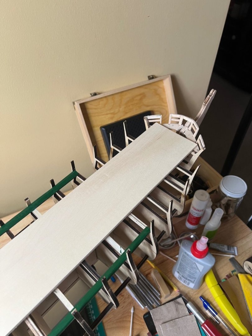
Three Waterway sections completed - 2 to go. I went to Hobby Lobby with my daughter for a school project and found a piece of 3/16x3” basswood, so I decided to fashion the bow waterway in 2 sections vs the Hunt plan to use the supplied wood and use 4 pieces. The phone cam makes the bulwarks and keel look bent (they aren’t!). I’ll add the planksheer when the Waterway is completed. You can see where it was necessary to sand and shim areas for the decking. Question to the Conny builders about the mast reinforcements. I’ve been wondering if I should’ve cut the foremast reinforcement tab - the laser cut parts form a tab that rises (the mizzen and main mast sections were flush). I was wondering if this was meant to encourage the correct angle, or extra strength? How did y’all deal with it? I can still cut it out but not sure if I should.
-
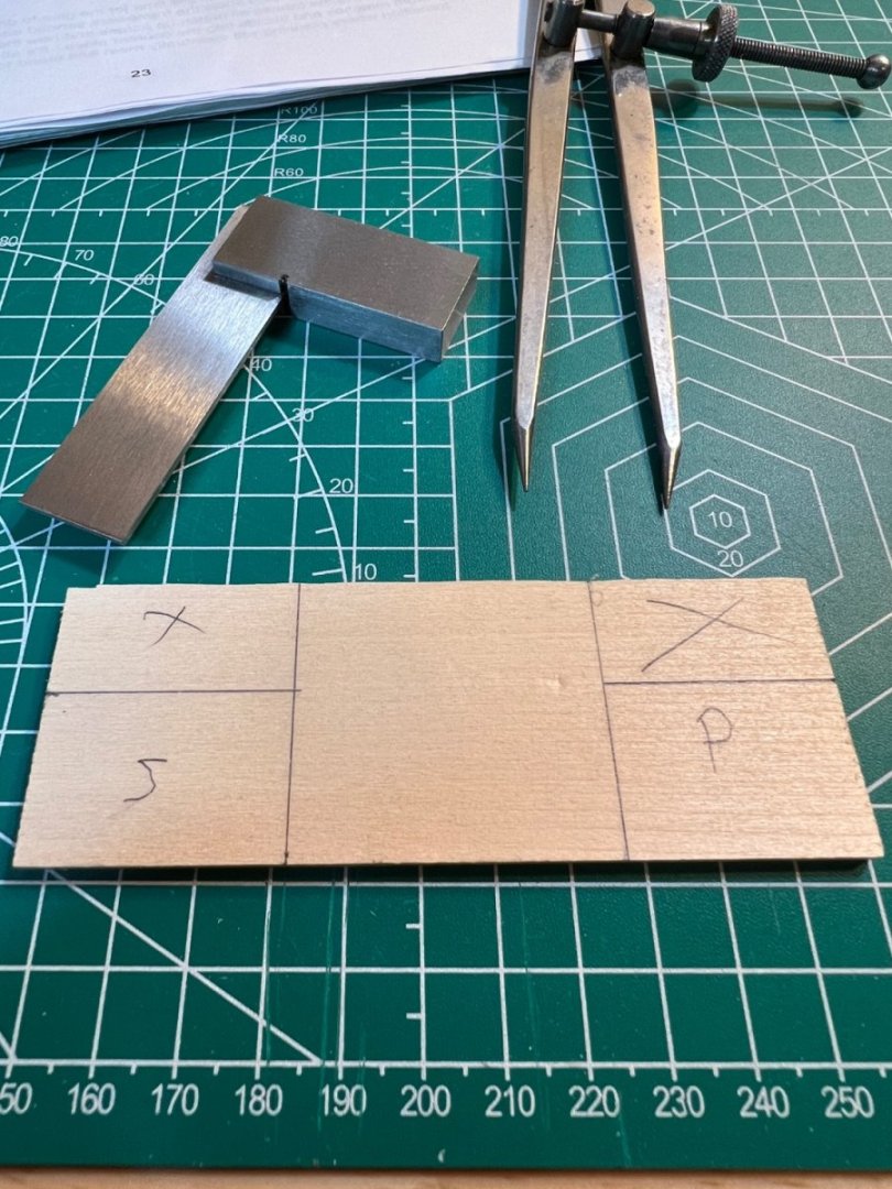
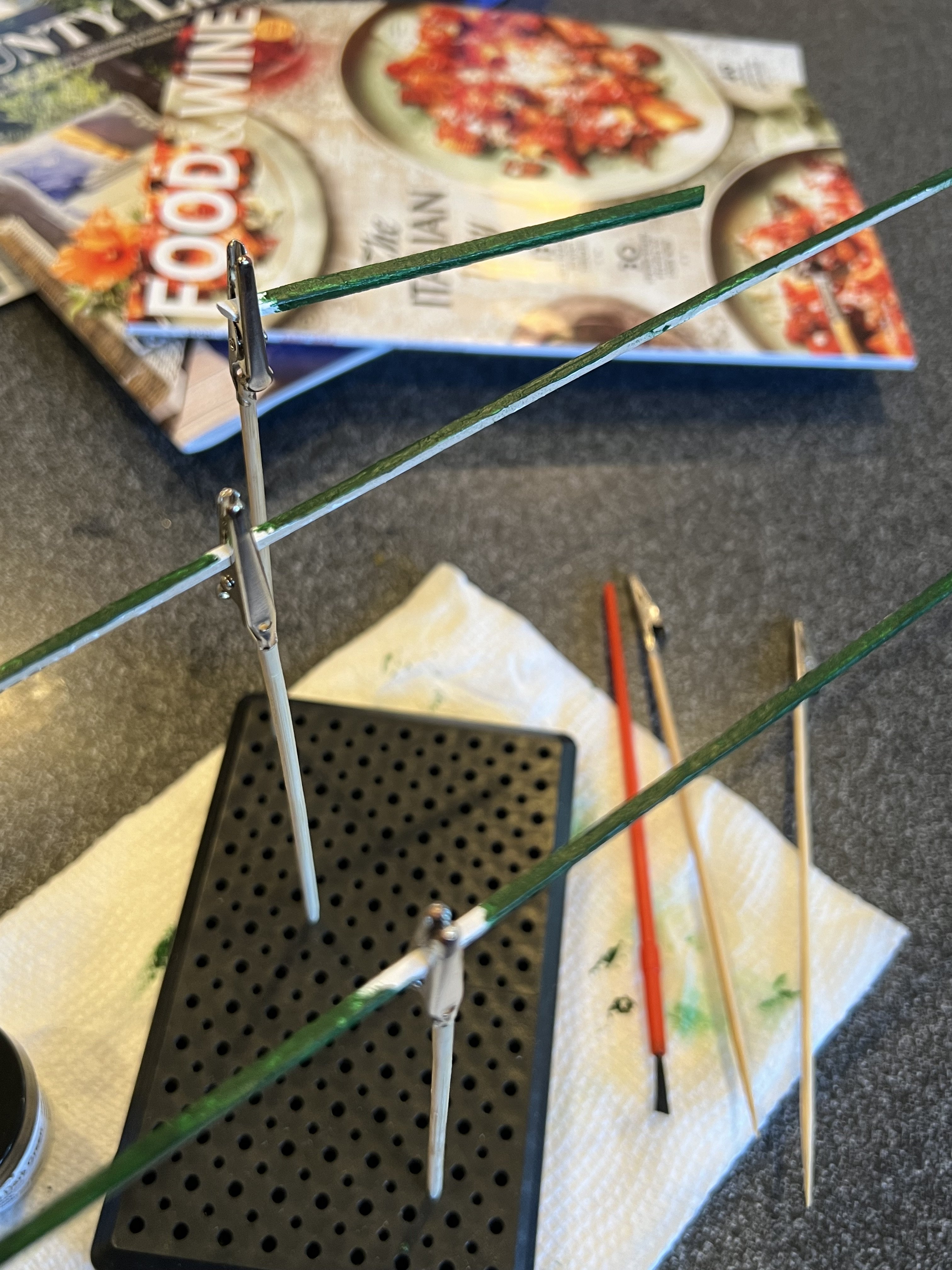
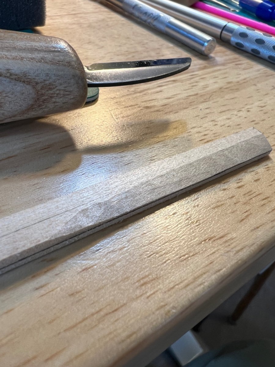
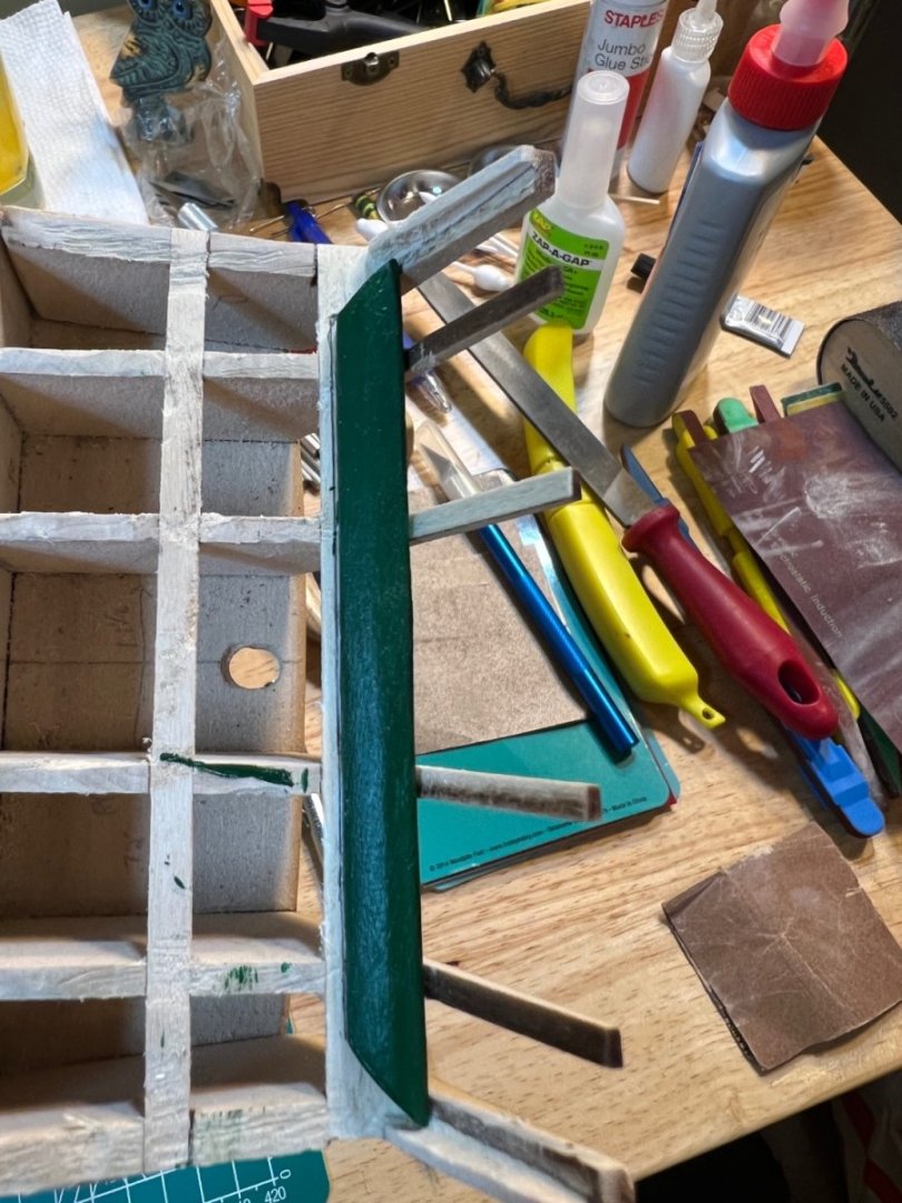
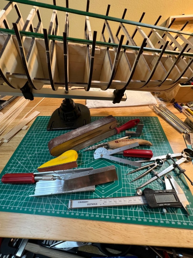
Waterway & Planksheer The waterway is made up of numerous unique angles and shaping. It’s a difficult timber to get right. If you’re using hand tools - it may be a true test of your patience, perhaps more than skill. I won’t get into the detail, because I simply followed Hunt’s cook book. For plank bending - I cranked up my on demand water heater by 50 degrees and used the hot tap water to bend the planks (gently!) by hand*. It took a few attempts to heat - then clamp - but each time resulted in a better fit. I primed and painted the waterways using the Model-Expo USS Constitution paint kit - Bulwarks Green. I chose to fit, then glue the transom waterway first. Additional waterways and planksheer remain. I included a picture of many of the tools necessary. I missed a few - including the painting. *Every modeler will find their “special” talent. Mine is bending wood by hand. I utilize a modified soldering gun for extreme curves (typically bow and stern). For everything else - I simply use hot or very hot water (depending on the wood) and bend the wood with my fingers. Knock on wood - I’ve yet to snap one. Gotta say the waterways sure had my concentration.


-
Your planking is fantastic so I understand not wanting to paint it after all that work. Are you also going to forego the copper plating? I’m wondering if the copper would get a little lost in the natural wood color - or it may just be beautiful! I’ve loved this ship my entire life - so I’ll be painting and coppering. I’m actually considering using real copper plates if I can find them.
-
Peter - after sleeping on it - a new day brings renewed enthusiasm. I think Bob was well intentioned with his advice. As someone with his talent - he probably couldn’t fathom a slight deck curvature - but this was never going to be a museum piece. I agree with your comments - and I don’t think the issues I face can’t be overcome (as you pointed out - the aft bulwarks can be patched to the bearding line). In fact - I actually really like the lines developing on my Constitution. I’ll chalk up the elegant lines to the impact of an Italian Admiral visiting the shipyard and having lunch with Joshua Humphrey during construction. The slightly raised aft cannons were part of a highly secret experiment in frigate cannonry.
-
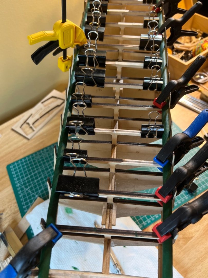
Well - I really appreciate your words of encouragement, @Der Alte Rentner. My worry though, is that it may be better to cut bait now and start over, then keep working and hit a project killer months from now as a result of my off-bearding line bulkheads. If you look at my 2nd picture above - there is a lot of play in what should be level. There’s really no amount of sanding and shims that will make up for a 1/4 inch concave curve. And if I do that by say, steaming a curve, what will the ramifications of a slightly curved deck be 4 months farther into the project - will I have to stop then? I’ll have to ponder this decision. Here’s what Bob said, in part;
-
So - bad news. After working with Bob Hunt - I’ve decided to start over. I will be calling Model Expo for replacement bulkheads, Keel and filler blocks. Apparently my first 2 aft bulkheads were not totally flush when set and too far above the bearding line. Though others were off as well. I did some sketchy sanding when I started in my zeal to get started. Bob said the fix is to dunk the offending bulkheads (entire thing since it’s more than just the aft 2) in acetone to dissolve the glue. I’d rather start over. It’s a bit demoralizing but I screwed up the bones of my ship. Cant have that. I appreciate all the help and advice. I’ll likely keep this log open and update it occasionally until I reach the Waterway again - then I will update more frequently. Carpe Diem!
-
Well that would be great news. After studying my work so far, I think you are right. I can’t see anywhere that I deviated so far from the plan that I’d have such a measuring error. It can’t be fixed at this point (at least I’m not willing to reverse my progress back to redoing the bulwarks), so I’ll continue and include a concave curve to my Waterway - along with the expected curve to accommodate the inner bulwark riser shape. The concave shaping is better IMHO than relying on glue to hold the Waterway. Thank You! -Andre
-
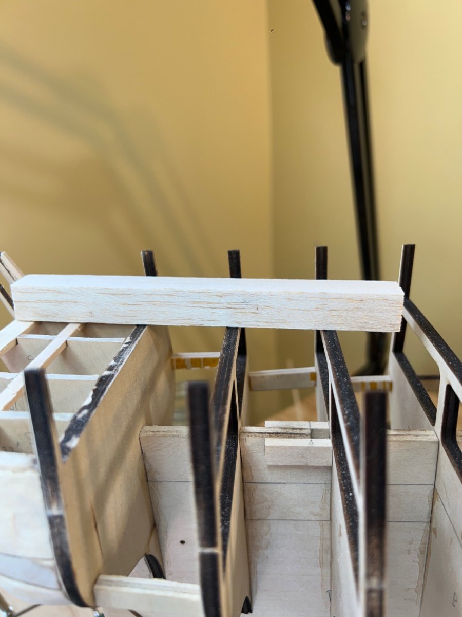
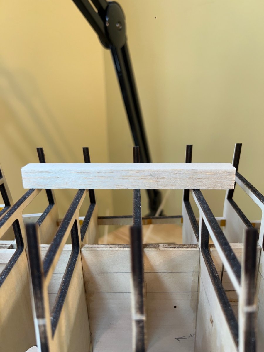
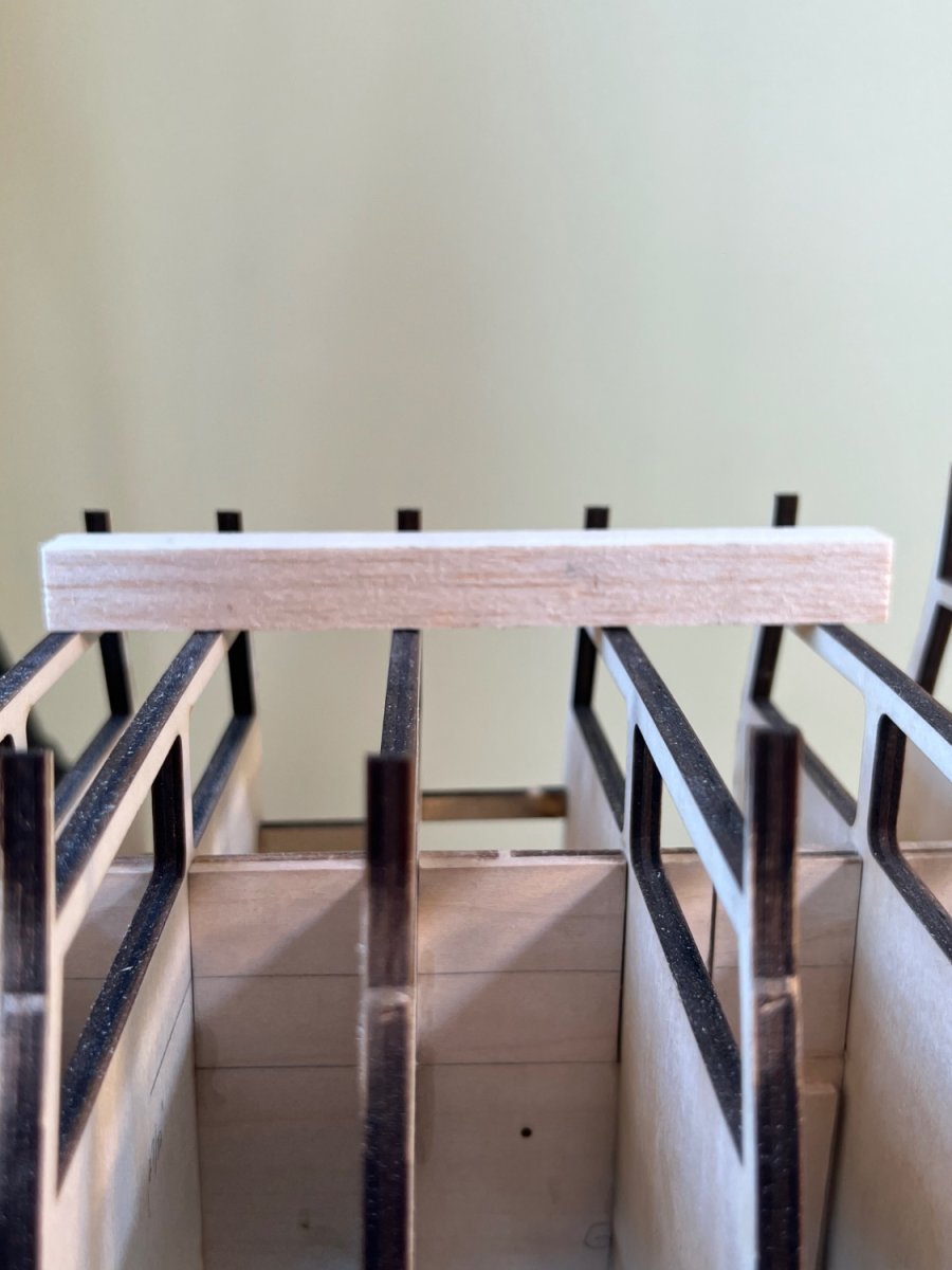
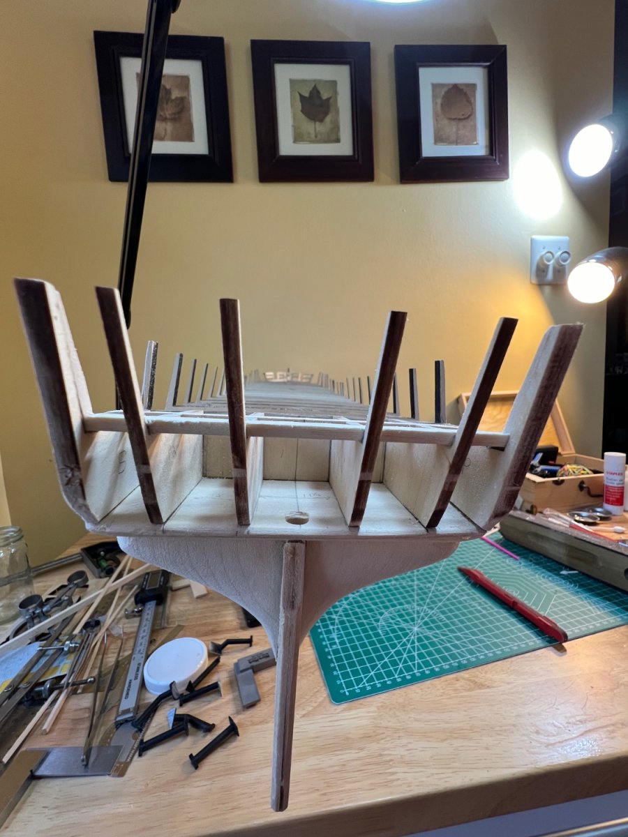
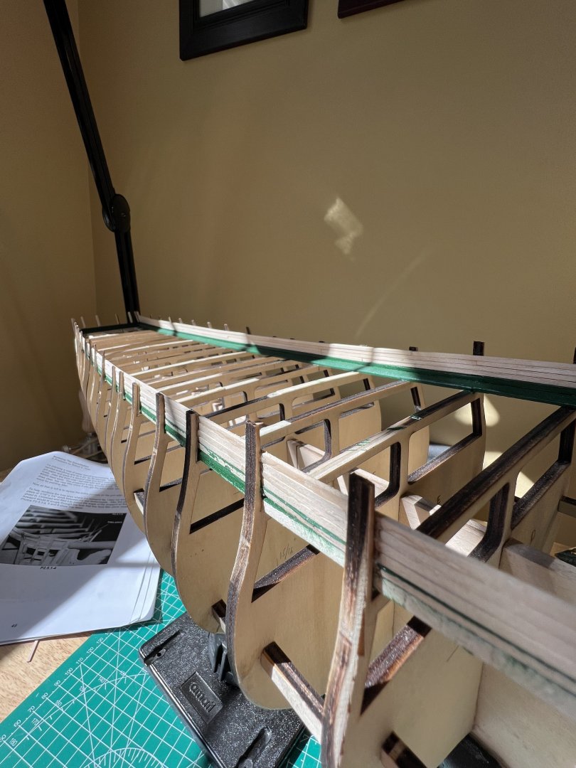
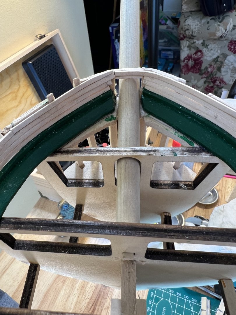
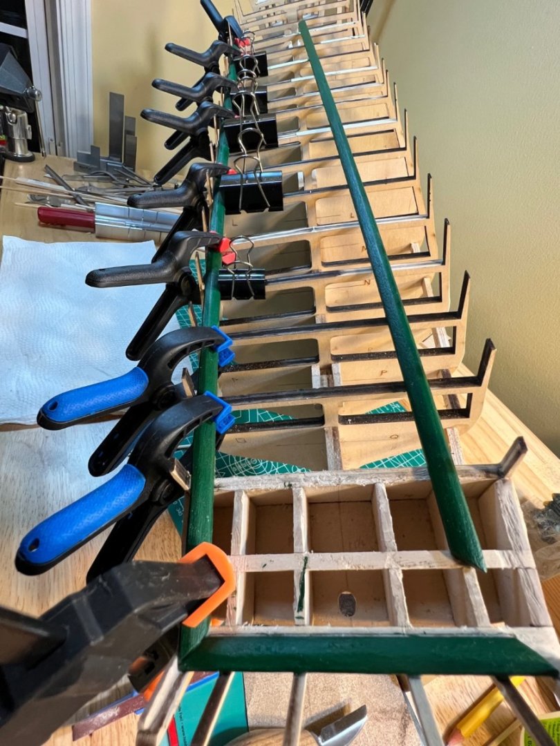
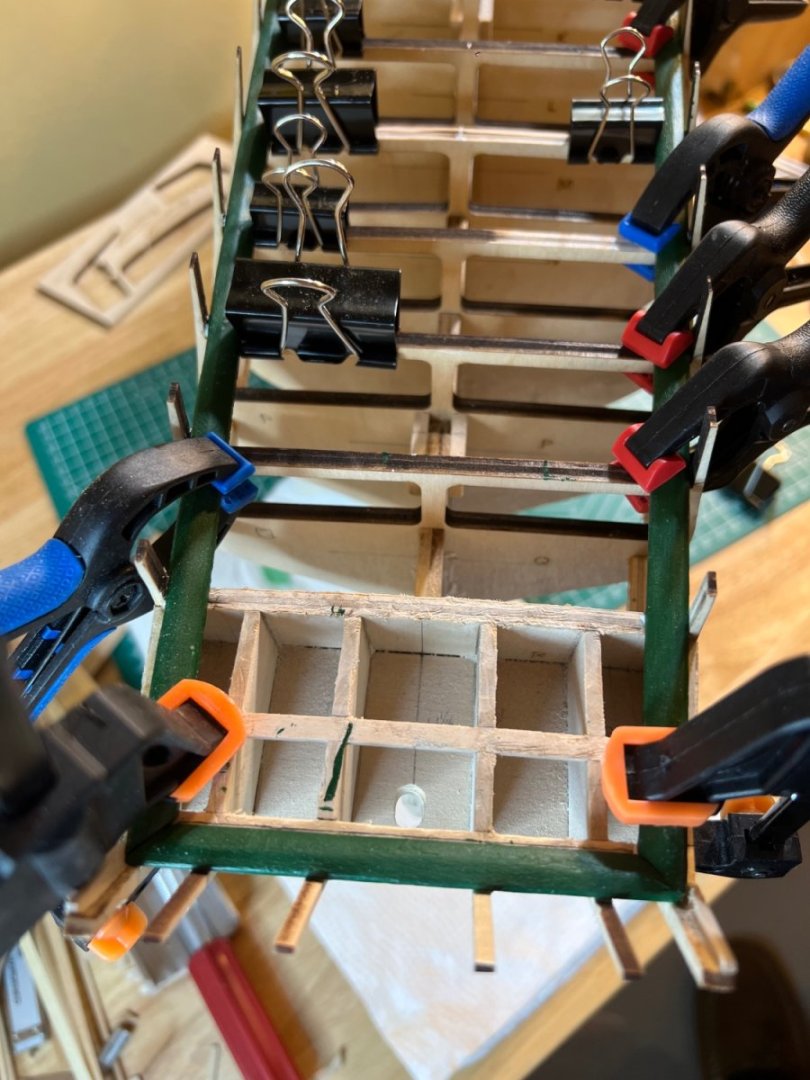
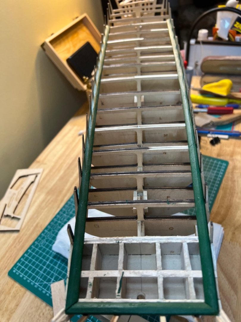
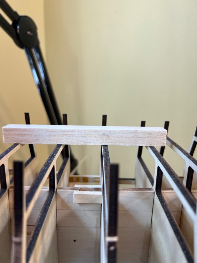
This is my current dilemma. As you can see - the bulkheads are rather level when tested in small batches of 4-5 - from the aft section of the transom all the way to bulkhead E. But when I lay the Waterway timber down, there’s a large gap. It goes away when I press on the timber, however — I have not seen or read anything referring to this concave element of the waterway project. Am I missing something or is gluing or steaming this concave shape just considered too obvious to mention?


-
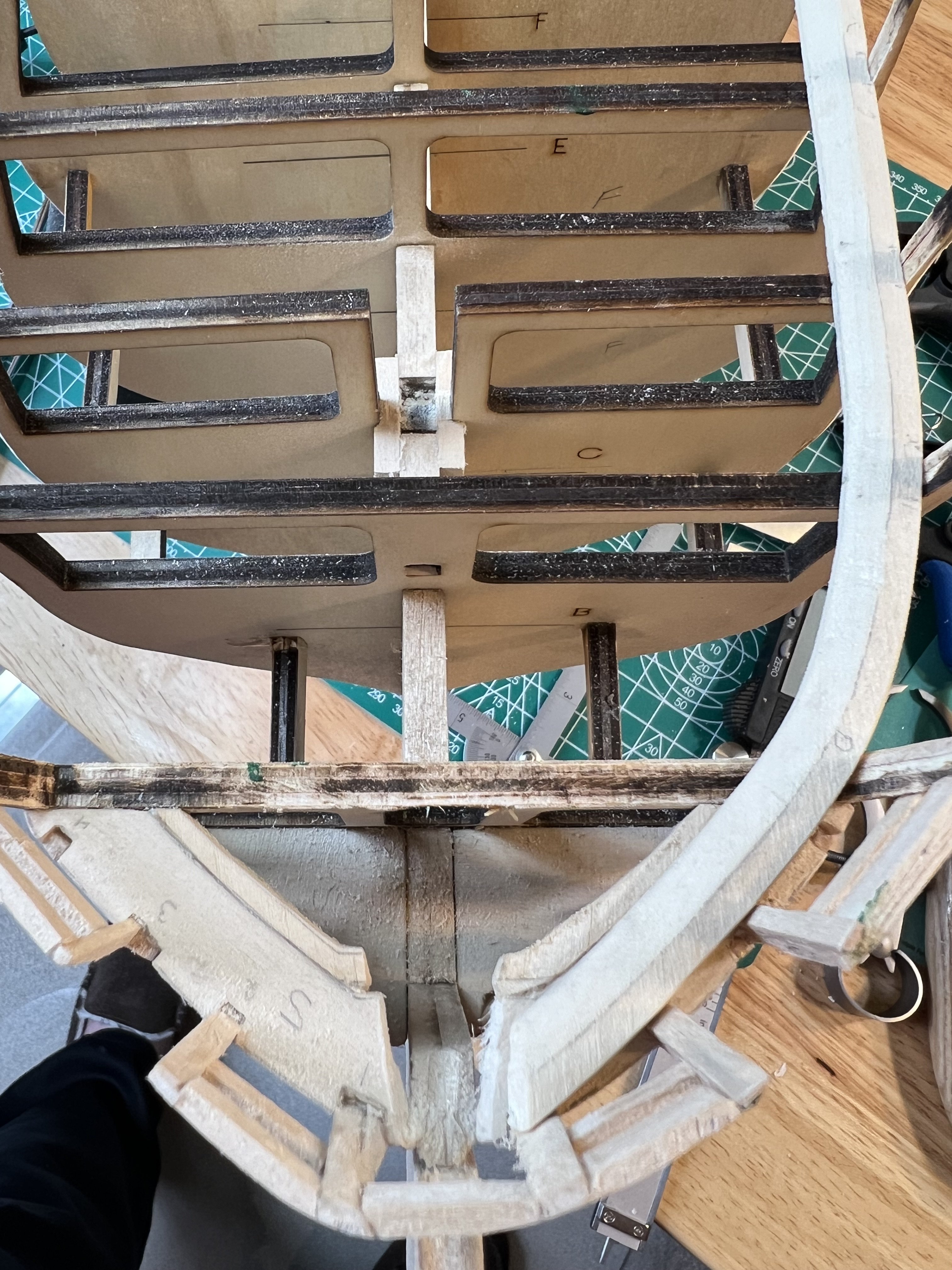
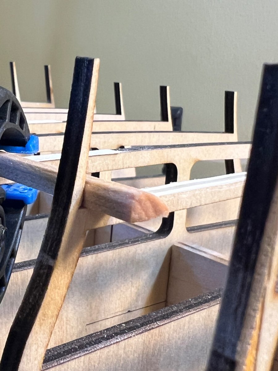
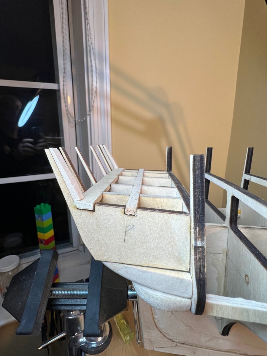
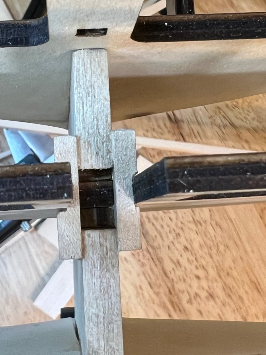
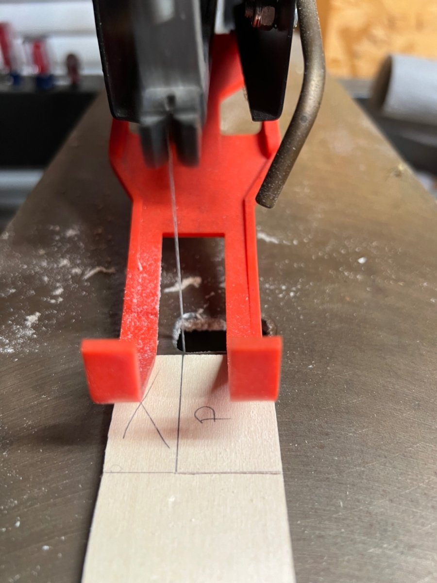
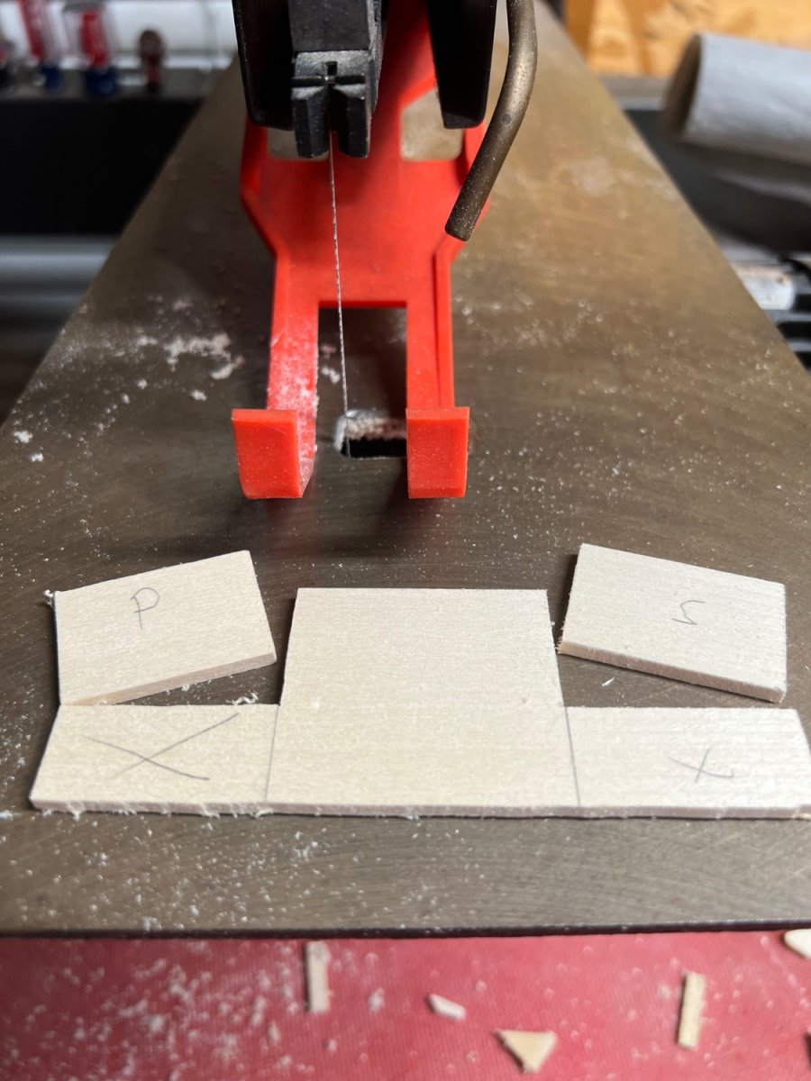
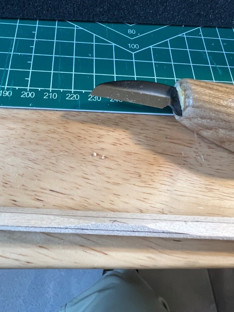
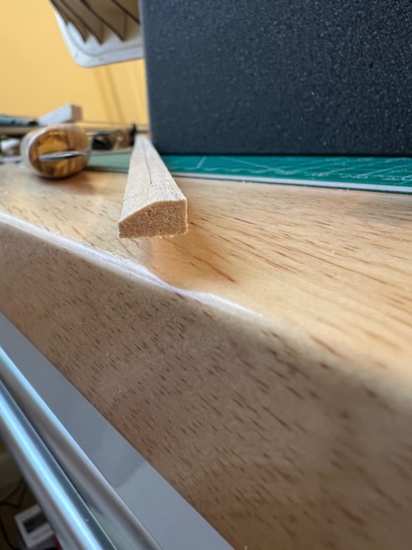
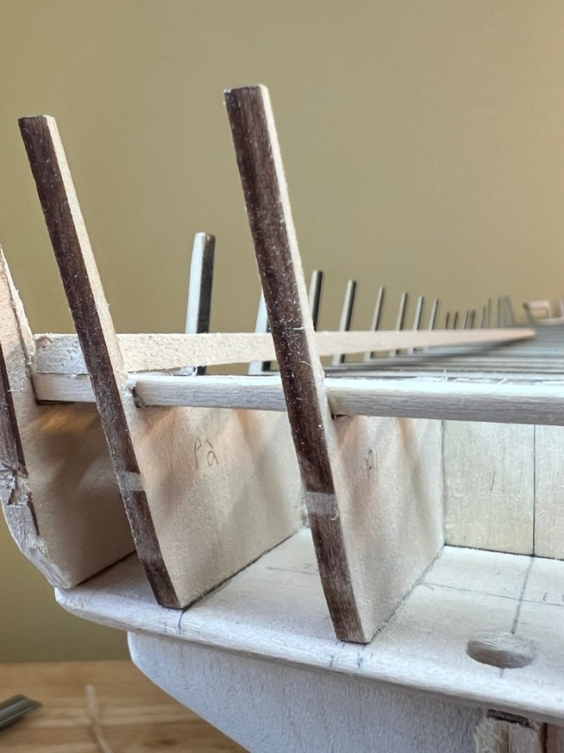
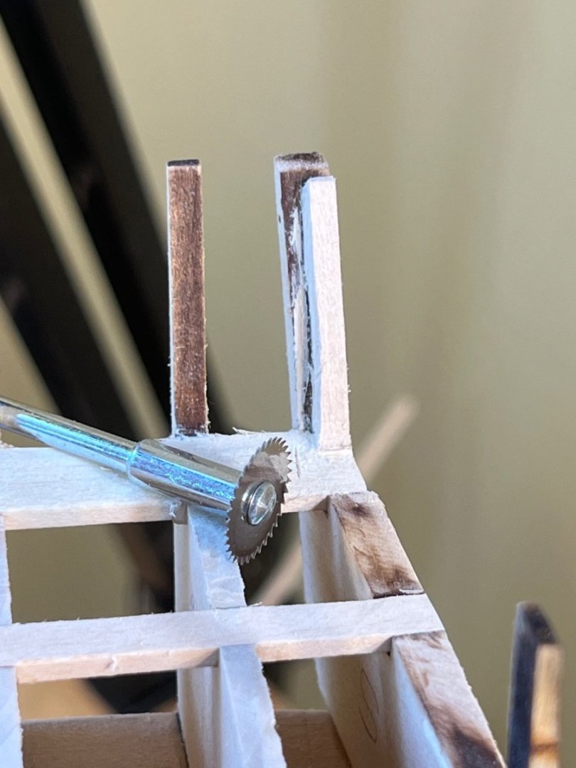
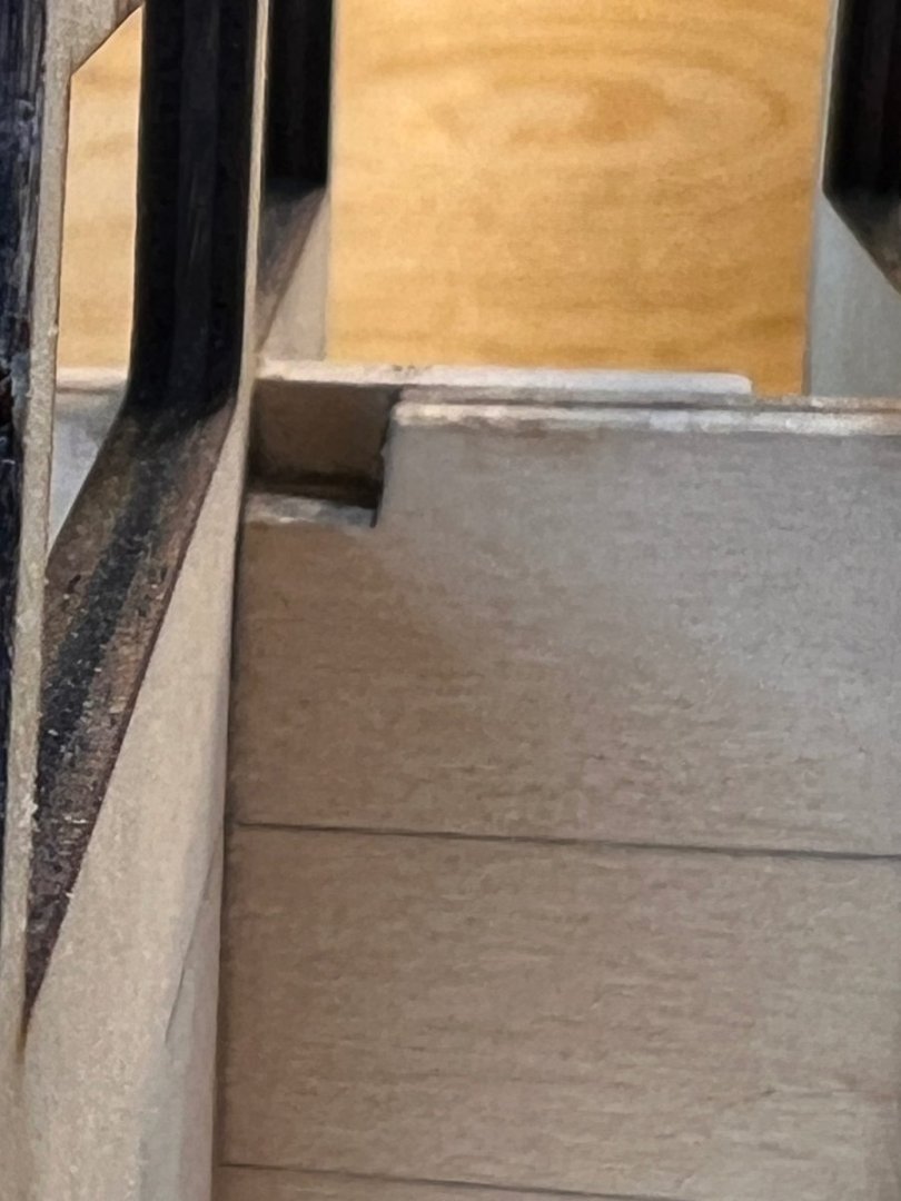
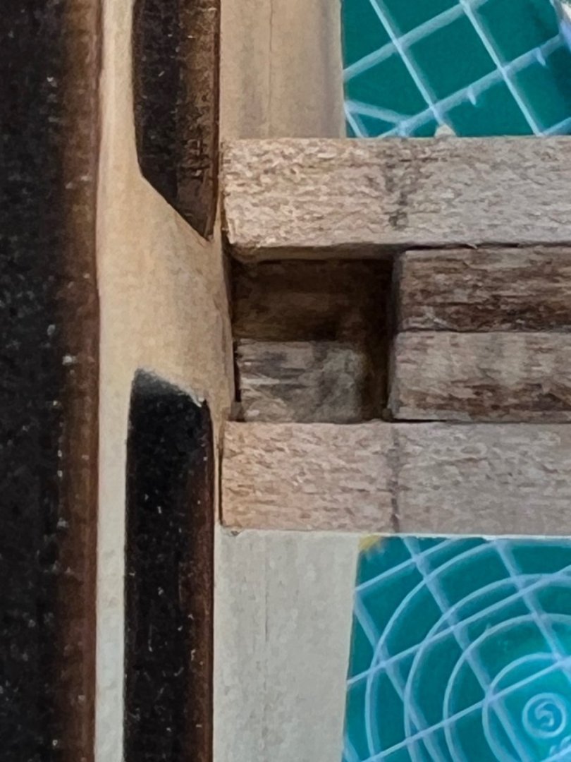
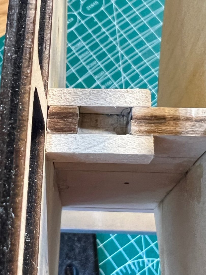
I was completely unsuccessful in using rubbing alcohol to loosen the strengthening timber. Snapping off the riser was the likely outcome. I used a saw blade attachment, #11 blade, and micro chisel and surgically removed the excess to create a plank pocket.
-
Looking really good! Dont sweat the symmetry issue. Nobody will ever see that once this is complete. I know we all care about that, but the truth is unless someone picks up your finished model and eyeballs it from stem to stern - it will never be noticed. And if someone does that - it’s grounds for expulsion from the party 🙂
-
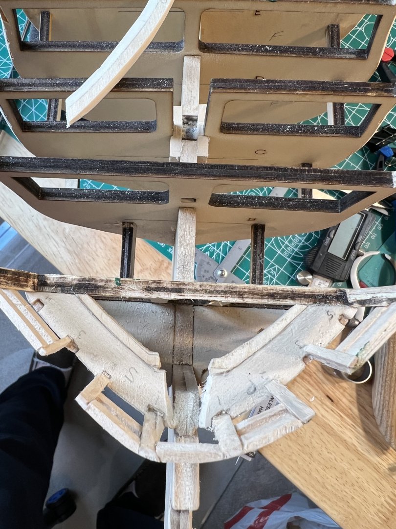
It looks like I’ll need to remove the strengthening timbers affixed to the outer transom frames, and cut them in half. I didn’t realize these were to form a pocket for the inner transom planks. I don’t want to try cutting them in situ because the skinny frame riser could snap. This will be my first attempt to debond the glue with alcohol. A second , potentially much more serious issue - my waterway timber doesn’t lie flat from the stern transom to bulkhead E. I found that my transom requires more sanding/leveling, but even when measuring from the closest bulkhead to the transom (R I think) - to E, it won’t lie even close to flat. The odd thing is that a metal ruler along the same path does lie flat. I hadn’t been accounting for the metal ruler’s flexibility when level testing. I will show a picture later. I know that the Waterway must be curved to follow the bulkhead risers, but is there also a shaping required to form a slight concave curve to the waterway? Any thoughts are greatly appreciated!!

-
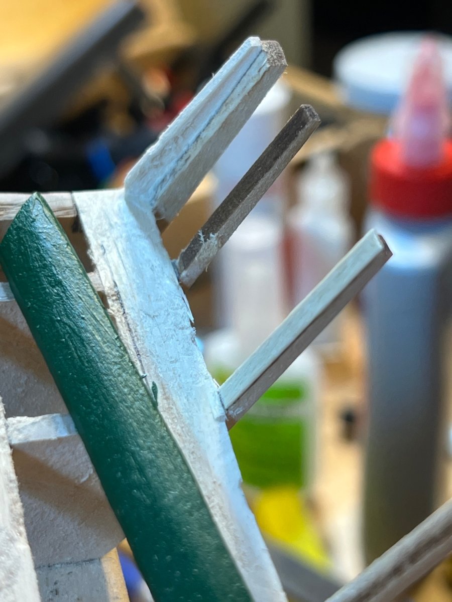
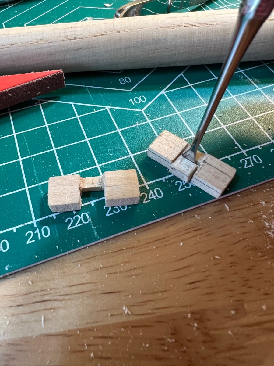
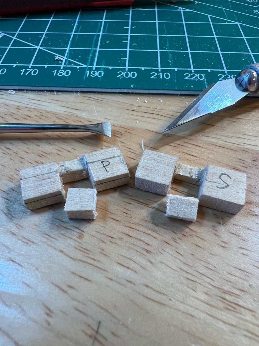
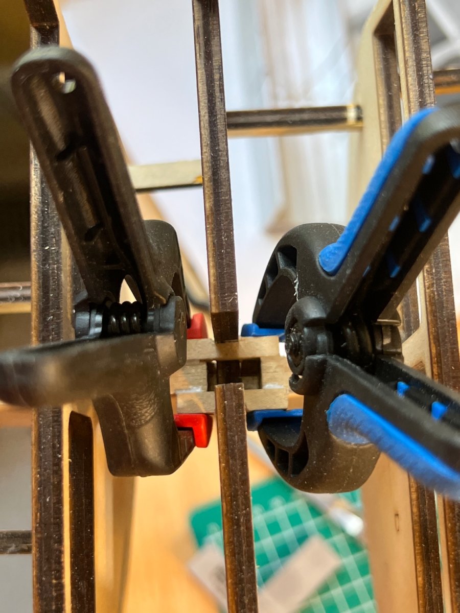
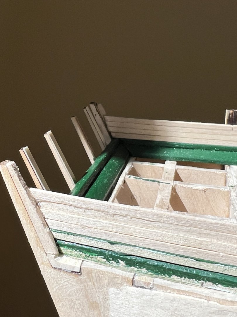
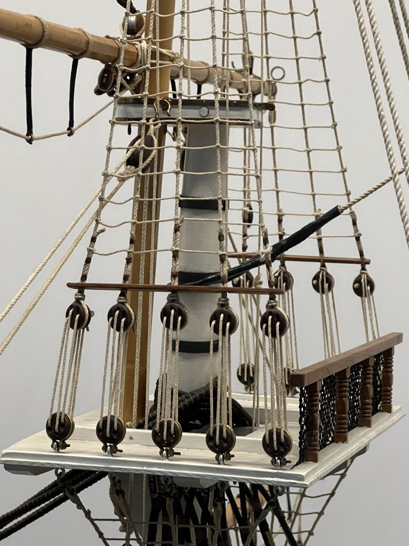
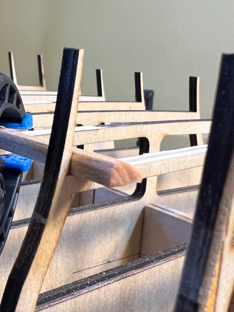
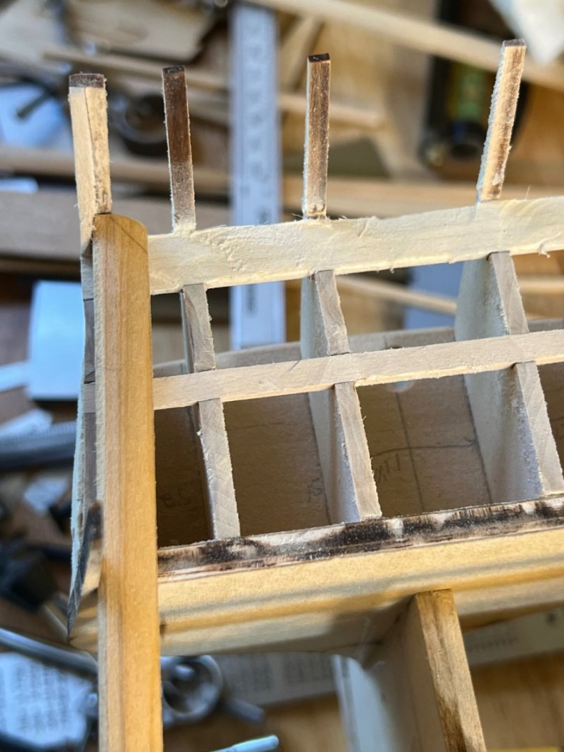
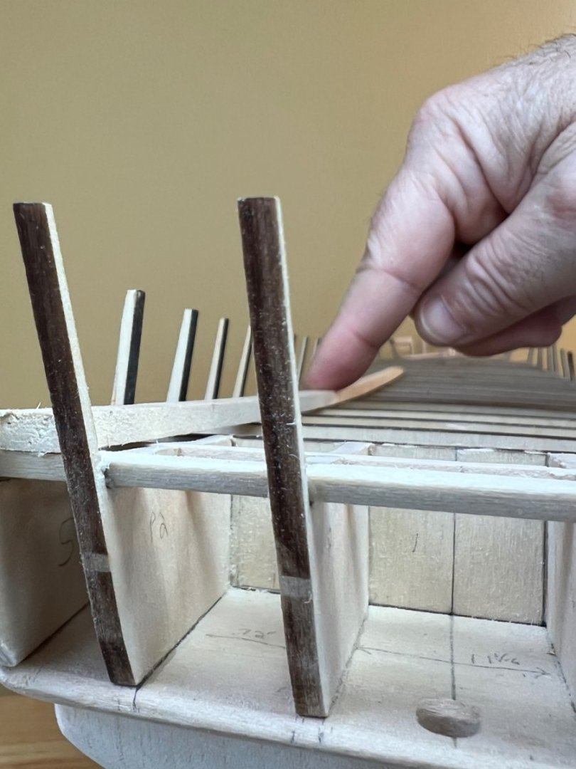
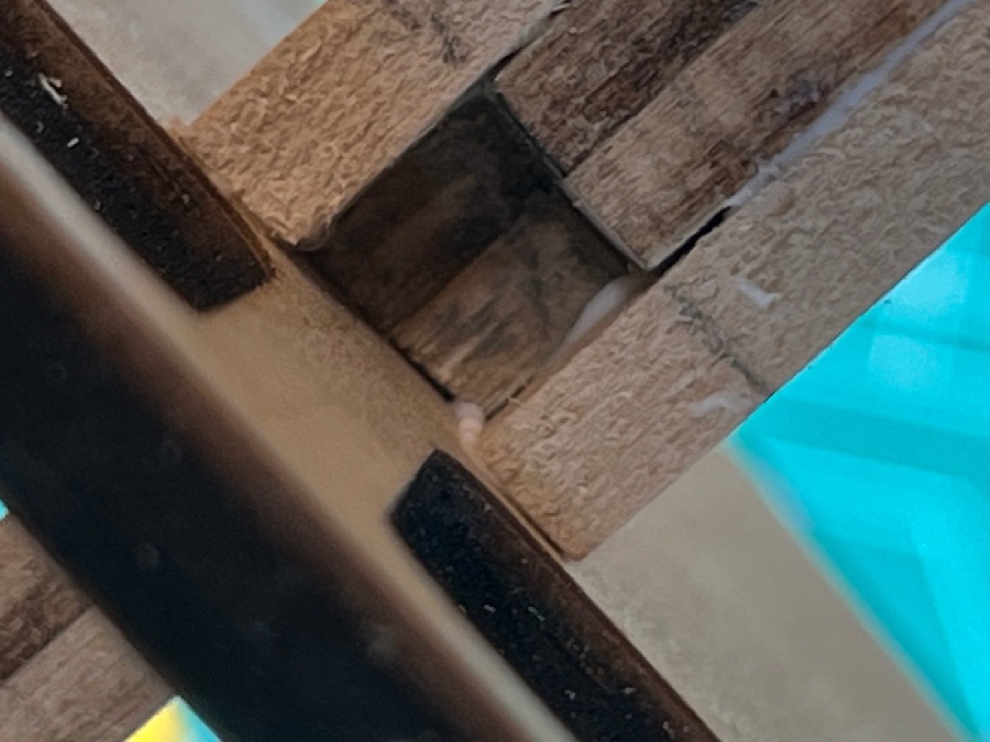
Mast Reinforcements These were fun - a simple walkthrough of the practicum steps. I utilized my micro mitre box, micro chisels, and a sharp #11 Exacto. I used 1/8”x1/4” stock and measured to Detail 2-E of plan sheet 2. The mizzen and main masts are just a measure, cut and glue exercise. The fore mast requires a little effort to measure because the bulkhead rises into the mast slot. Note that your port and starboard support beams are unique so label them. Be sure to clean out any glue that squirts into the mast slot before it dries! I added a pic with glue and then cleaned out. That glue may be a bit of a PIA to get out when set. Upon reflection- I believe the model ship gods may be chuckling at me for calling this simple. They know what’s in store when it’s time to shape the masts to these slots.


-
Finished roughing out the Stern Transom. I don’t have enough experience to know how much more to sand, so I’m done for now. Between the 1” block sander and the Proxxon sanding attachments- fine tuning of this area should be an effort of finessing to the planks.