HOLIDAY DONATION DRIVE - SUPPORT MSW - DO YOUR PART TO KEEP THIS GREAT FORUM GOING! (Only 75 donations so far out of 49,000 members - C'mon guys!)
×


SUBaron
-
Posts
197 -
Joined
-
Last visited
Content Type
Profiles
Forums
Gallery
Events
Everything posted by SUBaron
-
I will take a look at those chapters - thanks for the heads up. I will be doing loads of tweaking - right now I’m a little concerned about “over tweaking”, so I tend to leave things a little rough. It’s typically easier to remove than to add (though definitely not always). For example, I’m not sure exactly how much sanding of the transom and counter I should do. No matter the sanding, there will be an odd space between the counter and transom that isn’t yet apparent to me how it will be planked. I put the ship aside today for a hike with friends on the Wissahickon Trail (Chestnut Hill area outside of Philly). It was a blustery but beautiful hiking day! Cheers Peter! -Andre
-
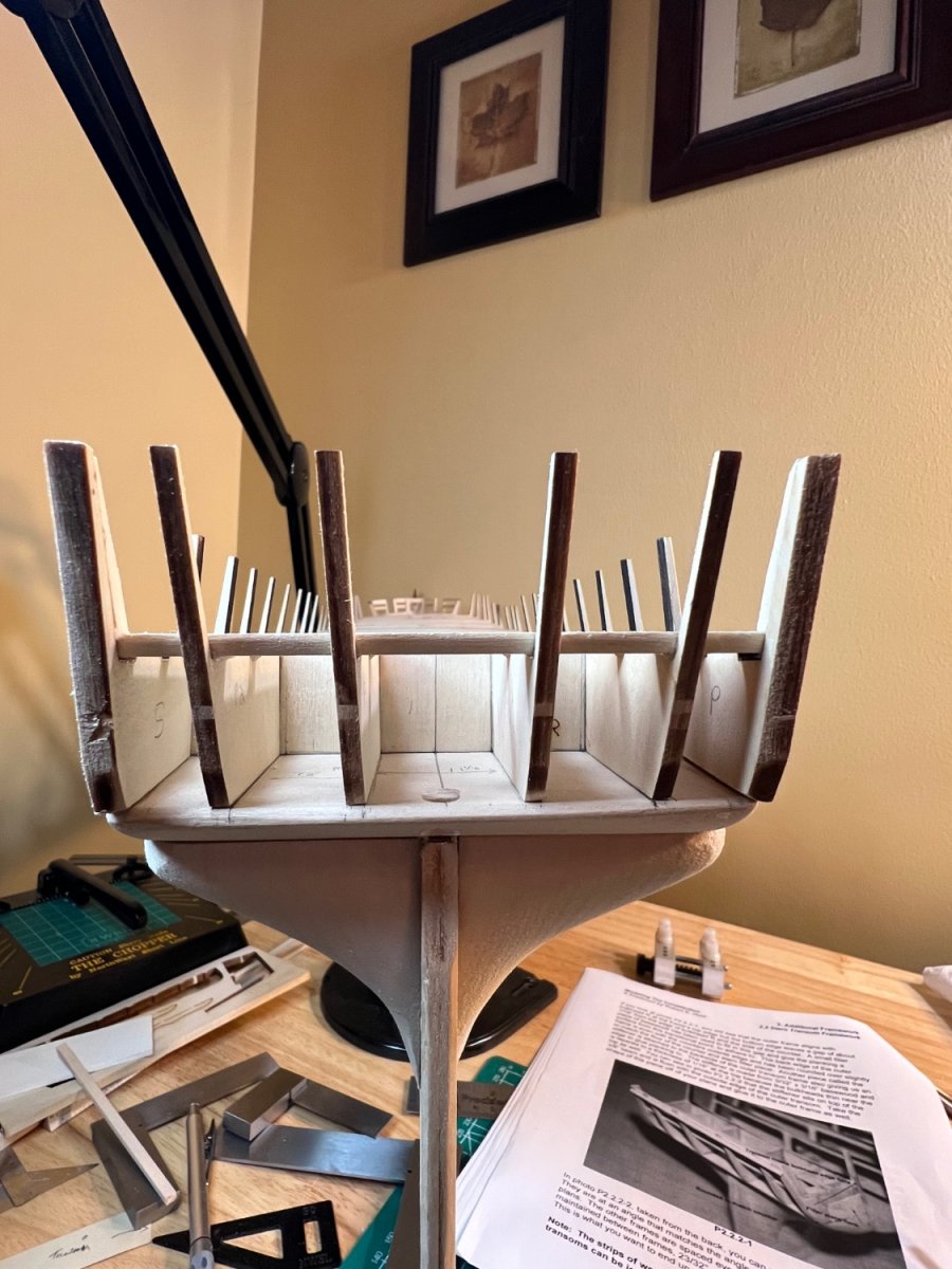
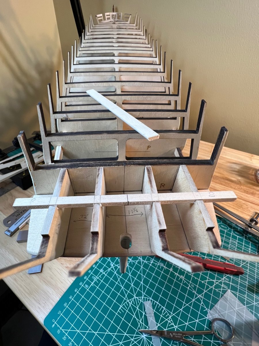
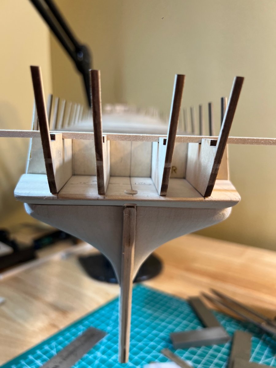
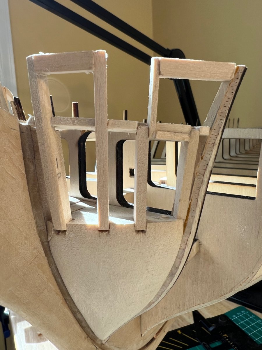
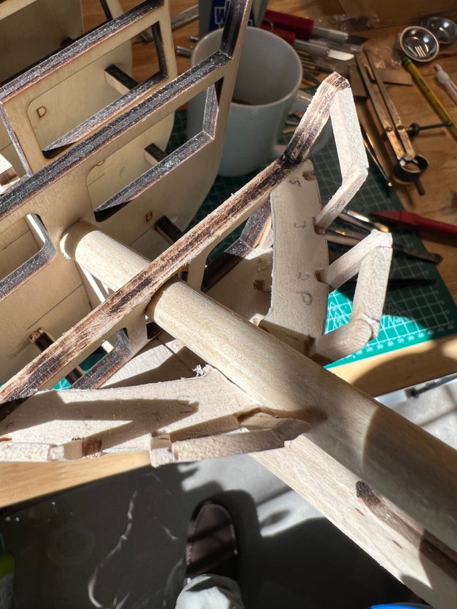
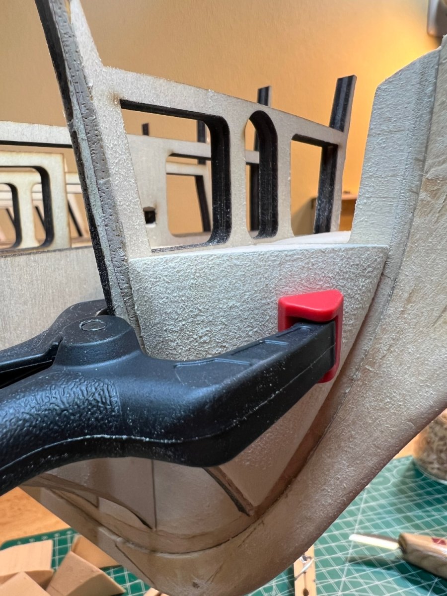
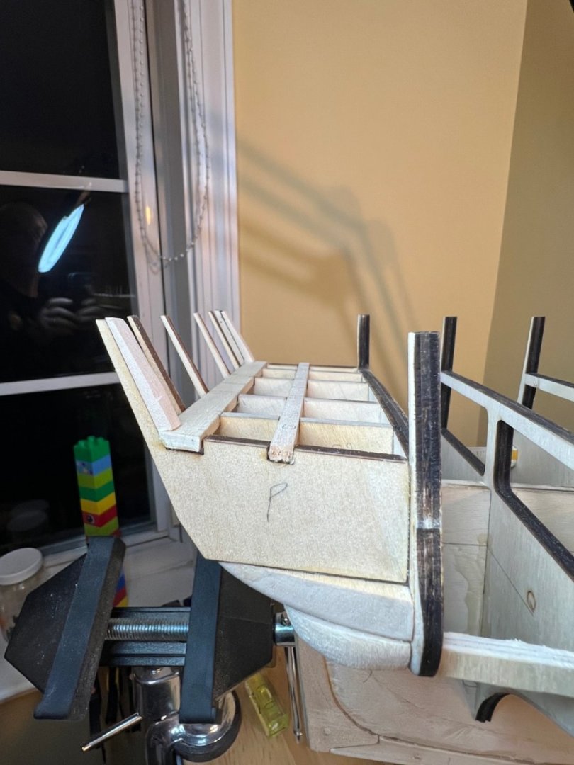
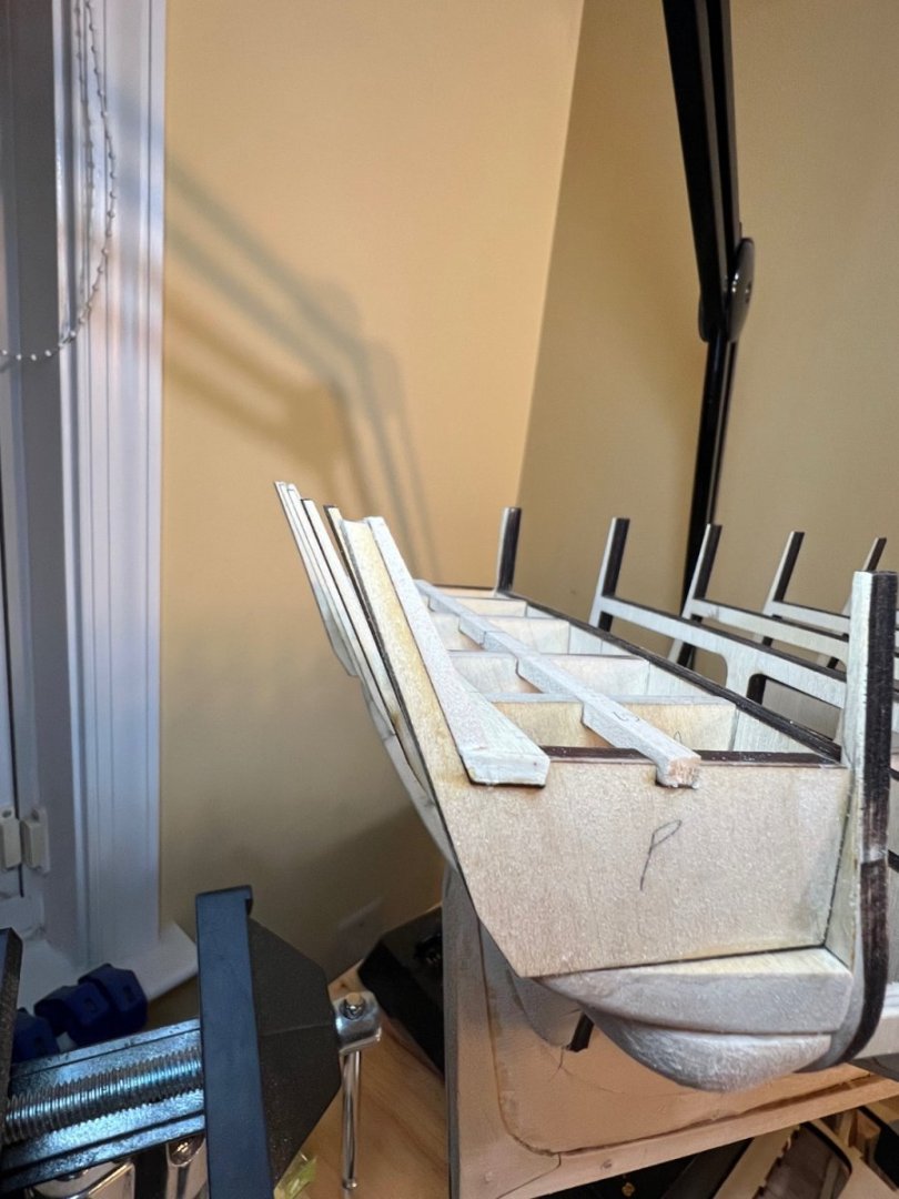
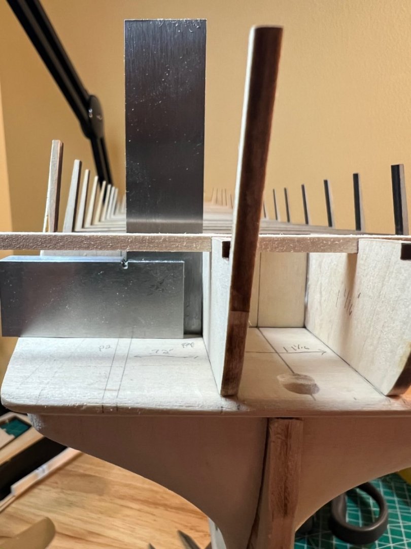
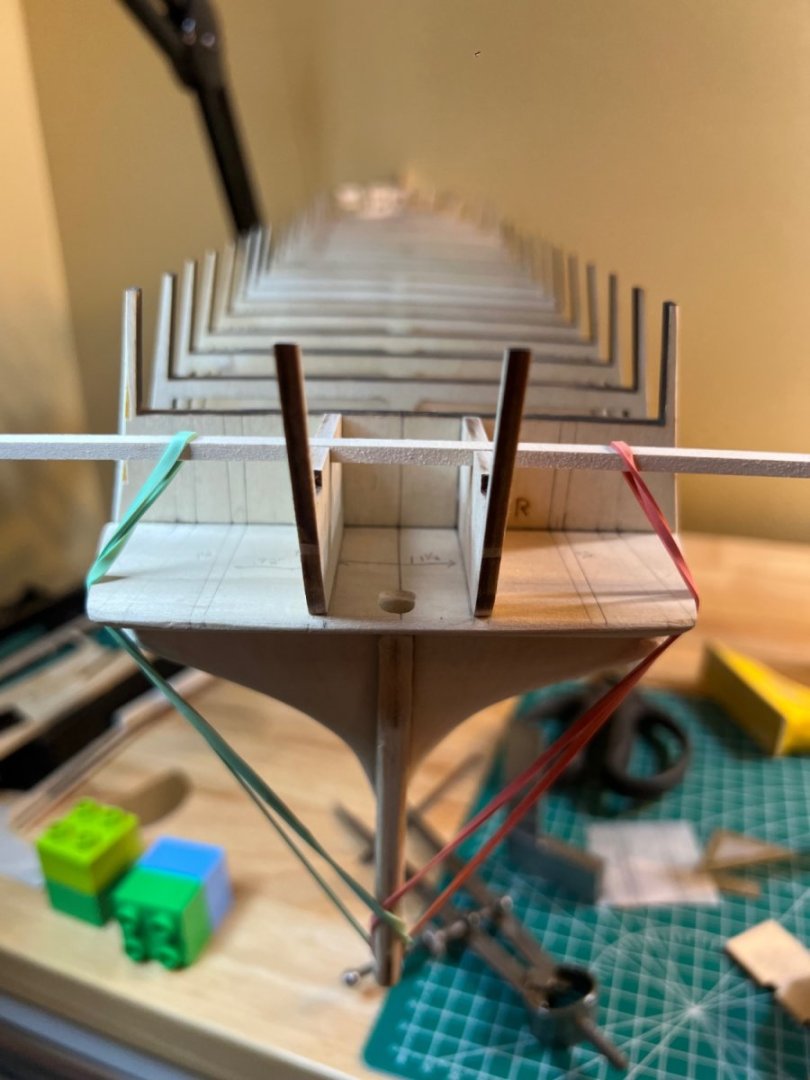
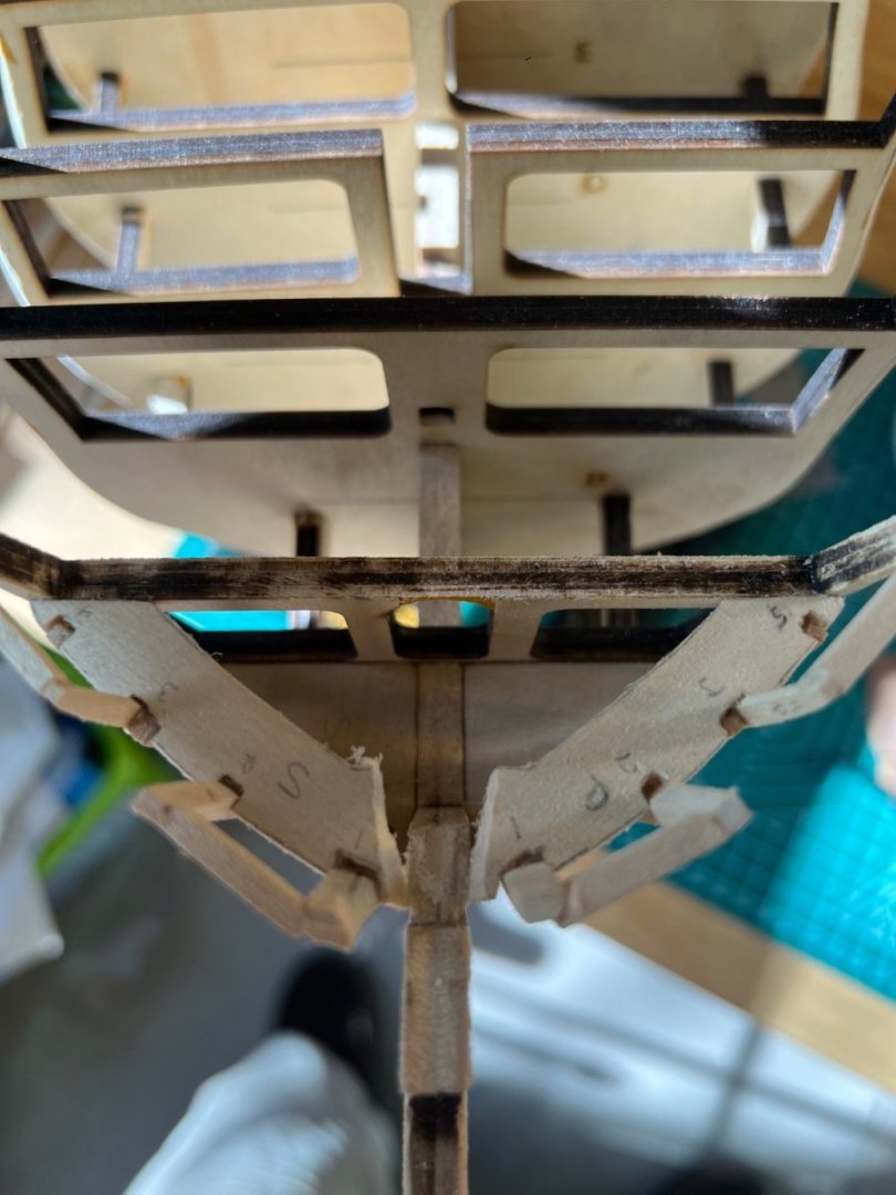
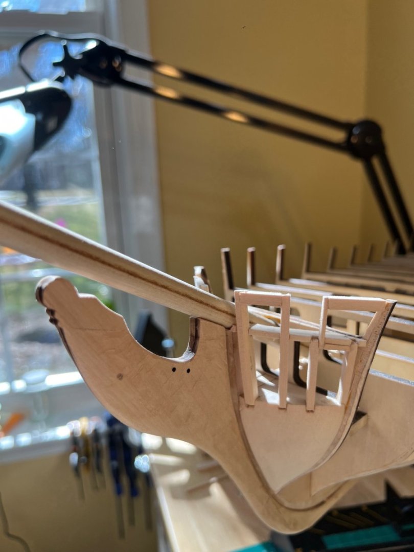
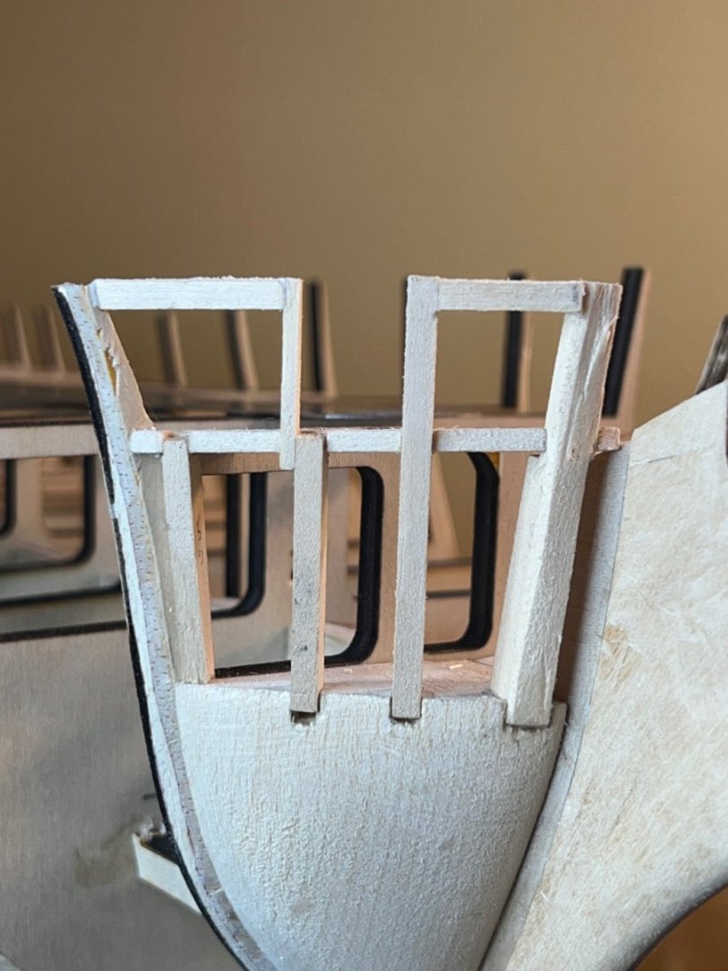
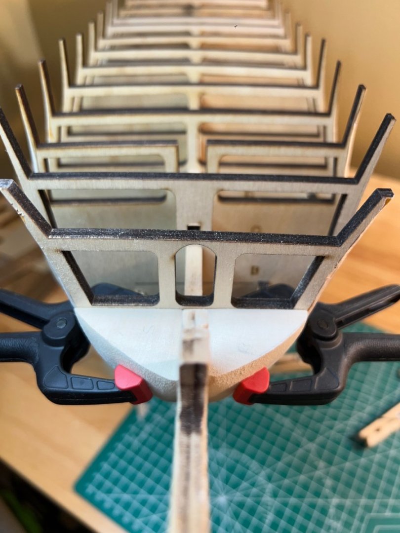
I decided to forego a trip to Target with my girls and affixed the transom end frames. The process was relatively straight- forward as directed by the practicum - and the sheet plan measurements. As has become my go-to method - I measured and fit multiple times until I was comfortable with the fitment. I then glued the starboard transom, adjusted for measurements, and quickly did the same with the port side transom. This way I could still make adjustments to both sides before the glue had fully set. I had pre measured 2 calipers for the top and bottom measurements so I could make adjustments before the glue set. In the end I attained 4 1/4” between the bottom of the outer frames, and just under 4” at the top (as per the sheet plans). I matched the outer frame angle with a piece of stock paper that I had traced from the sheet plans. I also eyeballed the setup with planking on my mind and made a few minor adjustments. I then cut, measured and glued the stiffeners, beveling to 1/16” at the top. Just in time because the starboard side thin upper transom had too much play. I ended up with a 1/16” space between the starboard and port end transoms and the edge of the counter. These spaces now require fillers. Before the fillers - I will begin sanding the frames - the outer frame bottoms need some TLC. Everyone loves a round bottom.

-
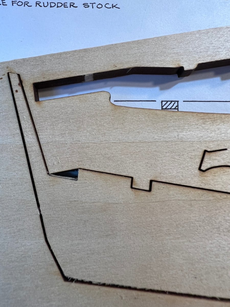
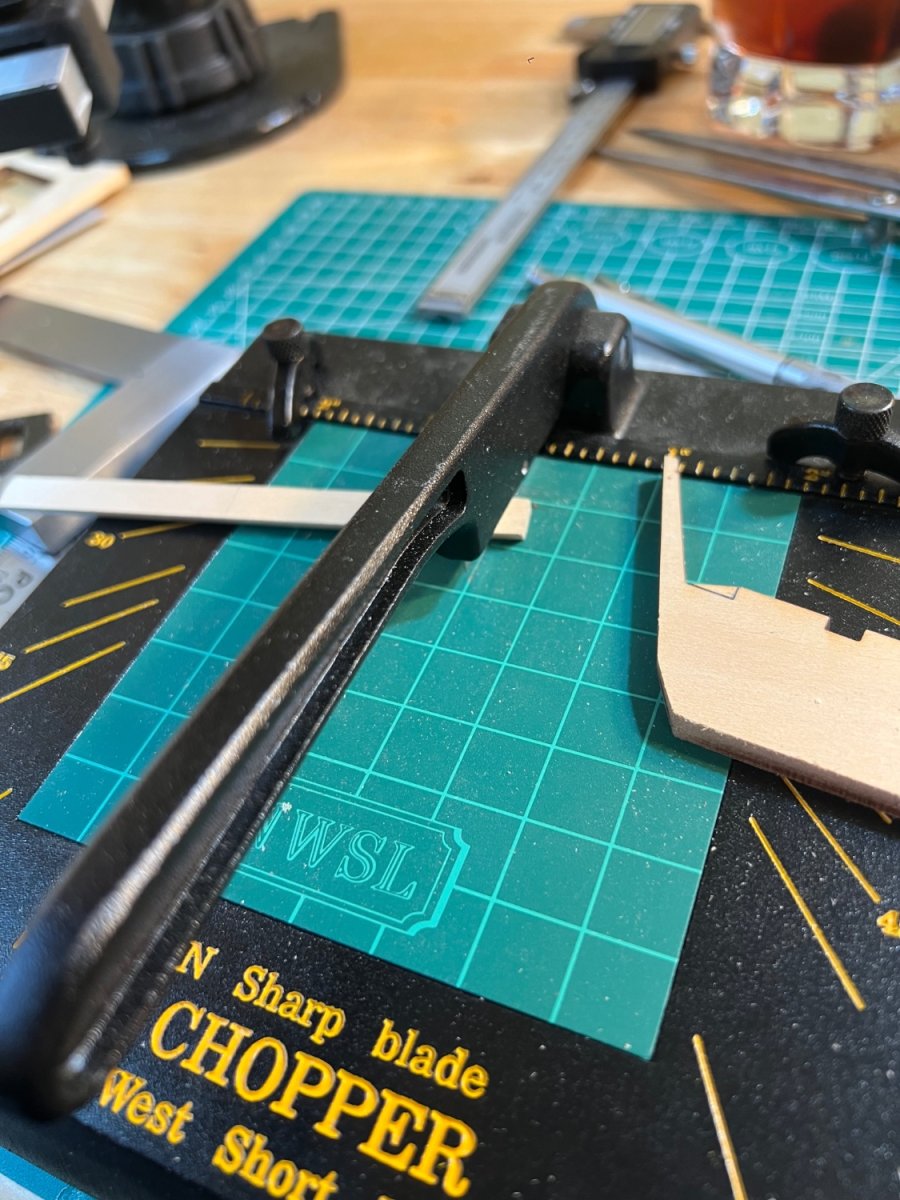
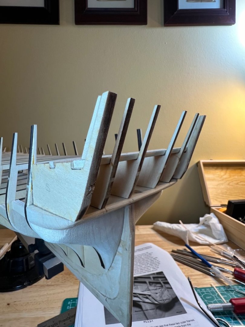
After some time shaping the aft support beam, I glued the 2 support beams over the transom frames - I chose to ignore the practicum’s direction to cut the aft beam in half - I believe this was to address an issue of a curved counter. I considered leaving these dry fit to help with the end frame fitting. But after a few attempts at a fitment, it became obvious that for my style, gluing in the support beams was best. It solved a host of problems, leaving a single challenge of shaping the outer frames to the existing set beams. One of the outer transom frames was left with an incomplete aft notch. I traced the angle to the matching frame, then used the Scroll saw to bite away at cut. This was preferable to attempting a clean blade cut on this manufactured wood.


-
I only perused the first few pages for now (I’ll be back!) - there are 14 - love it! Thanks for the link Jon!
-
Thanks Gregg! One of the things I really enjoy about this site is seeing the creative way folks utilize everyday items in their builds. I love a new tool, but love creative solutions as well. -Andre
-
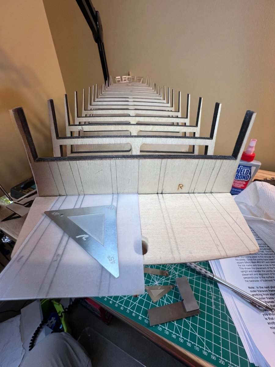
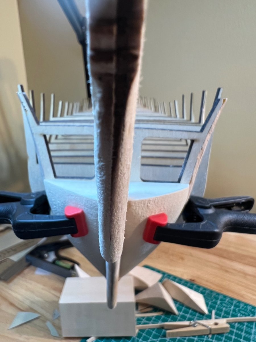
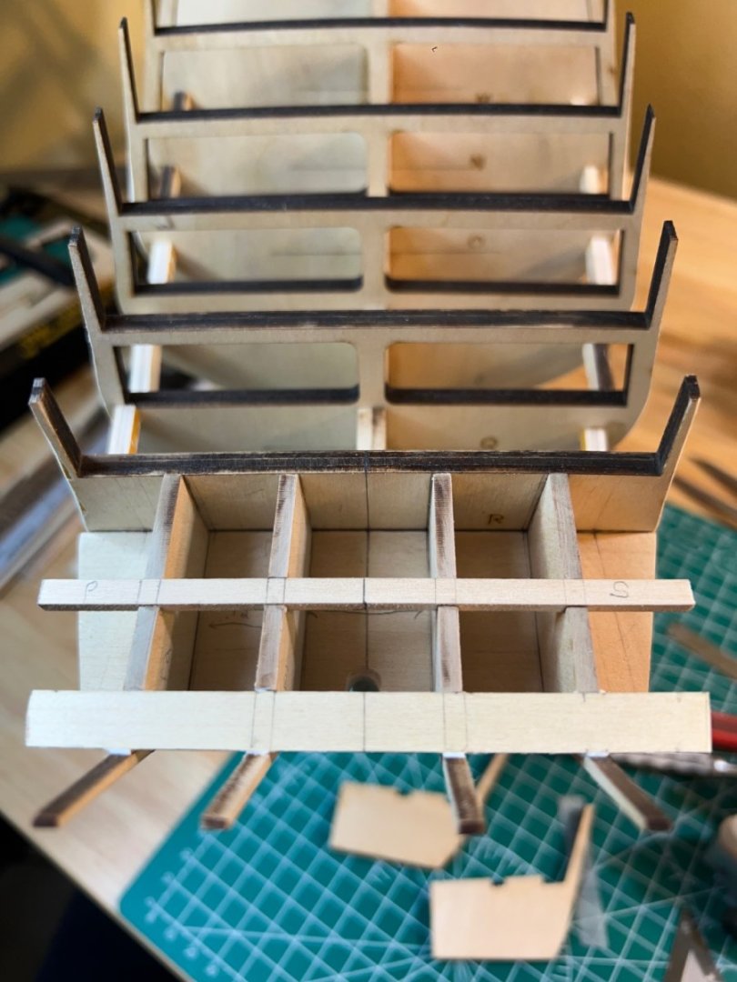
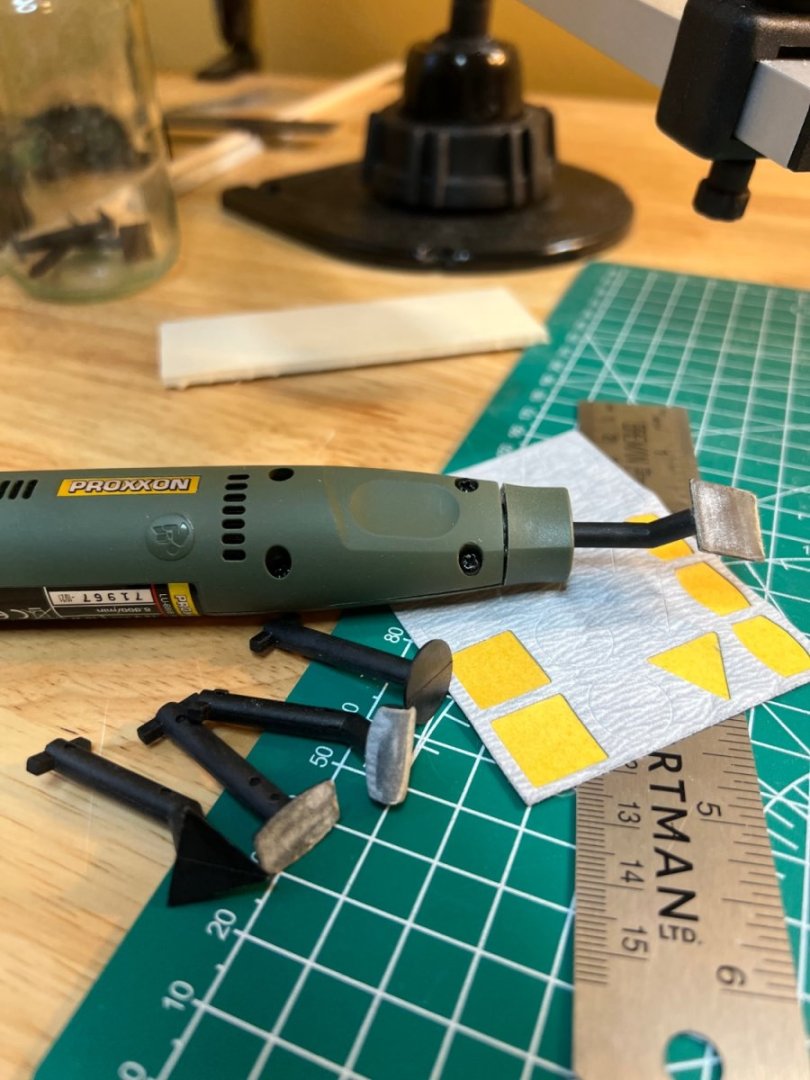
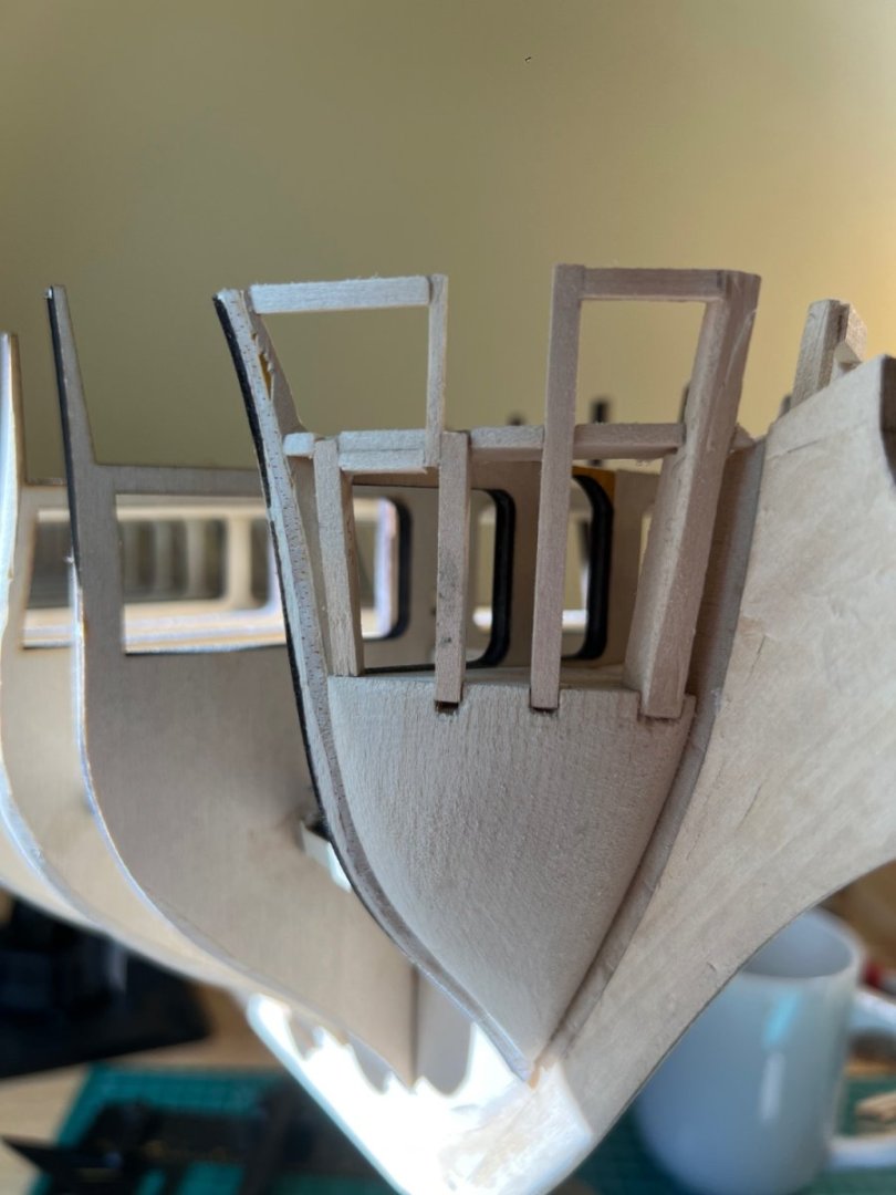
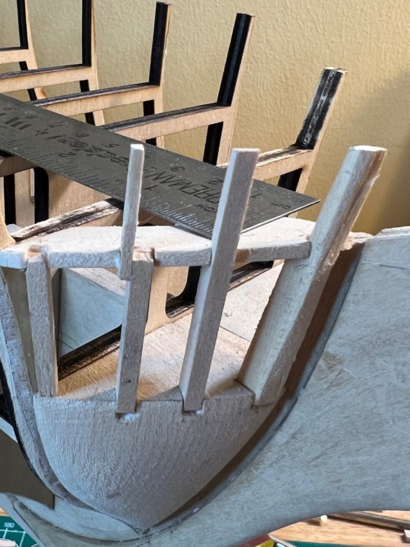
I attached the next two transom frames. My measurements were slightly off now due to my alignment work on the first frames. So I measured a few times with my digital caliper, glued, then measured and tweaked the placement again until I attained an exact decimal measurement of .718 from front to back between the frames. I almost waited too long to test fit the first cross timber support. Fitment required a slight tweak of the starboard frame that had almost set. I was concerned that it would break. The frames and cross timber will require some sanding to be true for decking. For the cross timber - I intend to sand it level to the frames, then utilize a caliper to assure uniformity where there isn’t a frame for reference. The Proxxon micro sander is a great tool for these delicate tasks - especially when the wood has already set and my usual sanders are too cumbersome (I use my block sanders a lot). I’m now working on the 3/8” beveled plank that fits against the back of the transom frames. The practicum directs that this be cut in two at the center line. I can see no reason for this. I think it may be b/c of the rounded counter issue Bob mentions. Did those of you who didn’t mill a rounded counter with a crest, create two cross planks here?

-
Peter - there are issues and there are Issues. The things that typically give me Issues don’t appear to be present in the stern transom build. We shall see!! It may be the first true test of my patience. Btw - I got a discount email offer from Micromark (apparently I’m now an “Expert” with them, with associated benefits:-)). I ordered the Proportional Divider (with spare tips), small brass clamps and the micro pocket measuring set (calipers). I don’t yet have a good tool for measuring angles, but I’m fairly decent at eyeballing things. And Legos!!! Doesn’t everyone have them? 😂 My daughter still loves doing them with me, so they’re not going anywhere ❤️ Cheers! -Andre
-
I’m glad the proportional divider is useful - it just seemed that those pointers would come in handy for precision checks. You’ve given me all the reason I need to pull the trigger on that purchase 🙂 I don’t have a 3/8” chisel, but I did get a 1/2” fishtail chisel from Lie Nielsen, along with small precision “scraper”. High quality and useful tools. I really like that company - as do others - the chisel was back ordered and took about 4 months. Cheers! -Andre
-
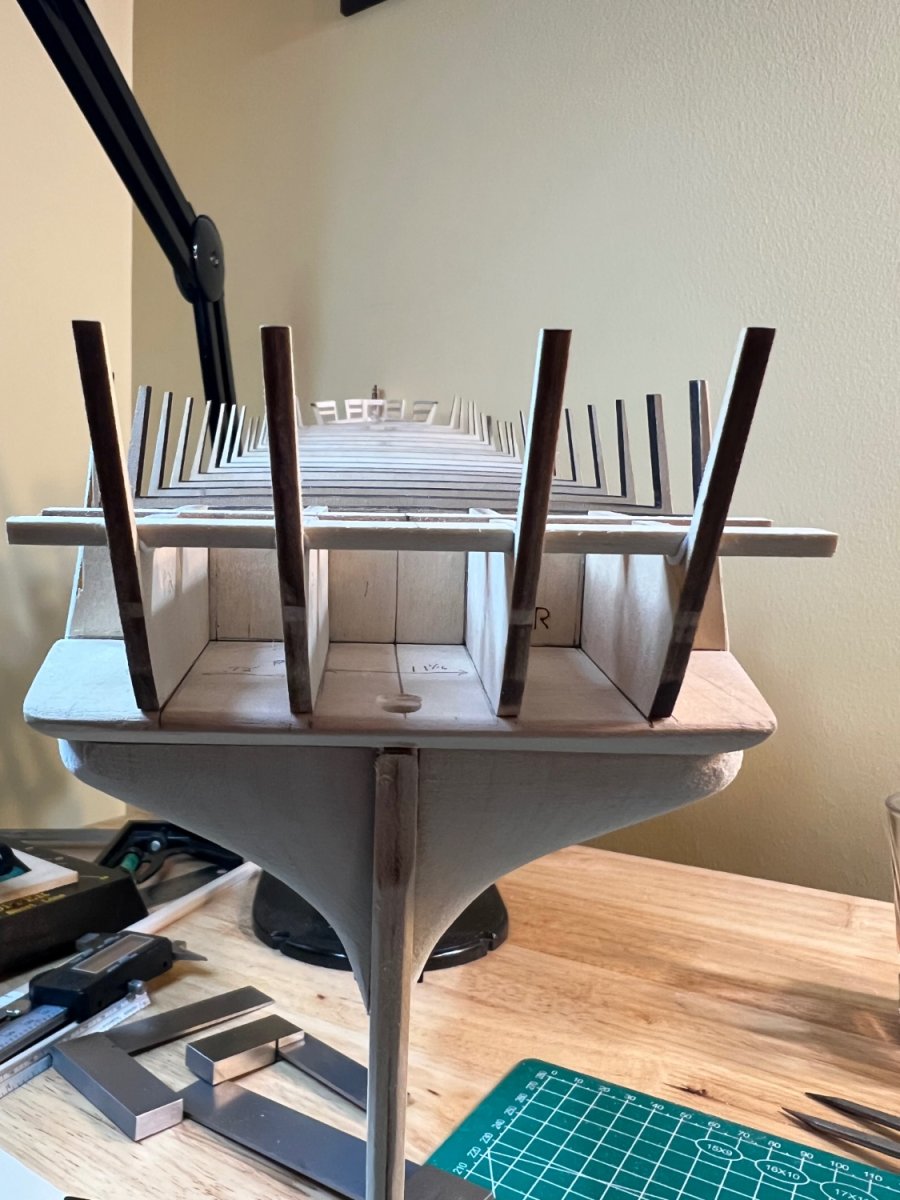
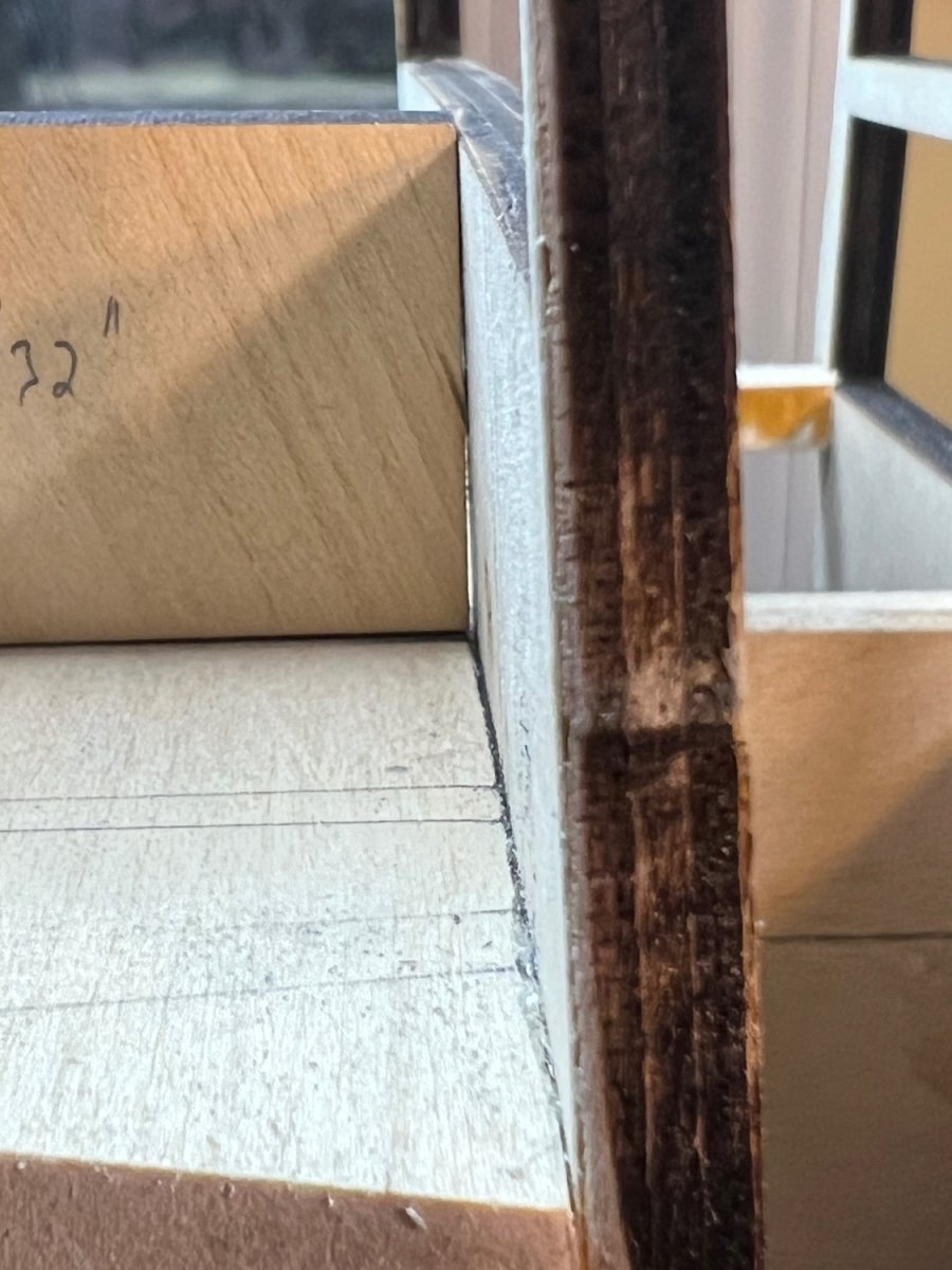
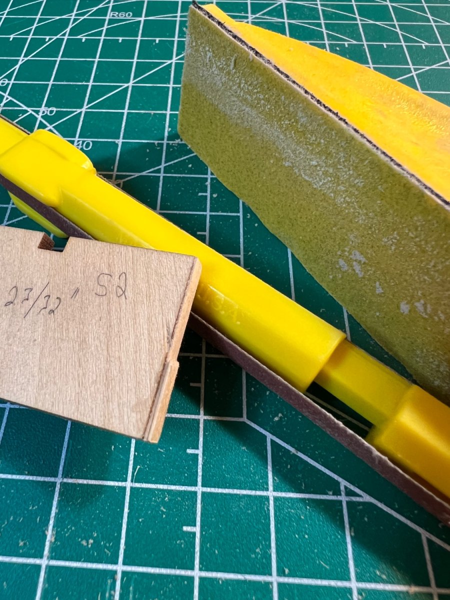
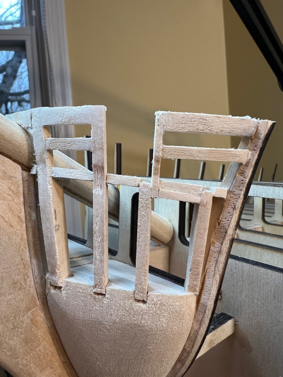
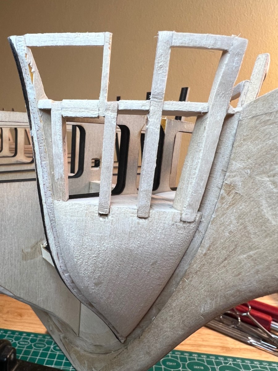
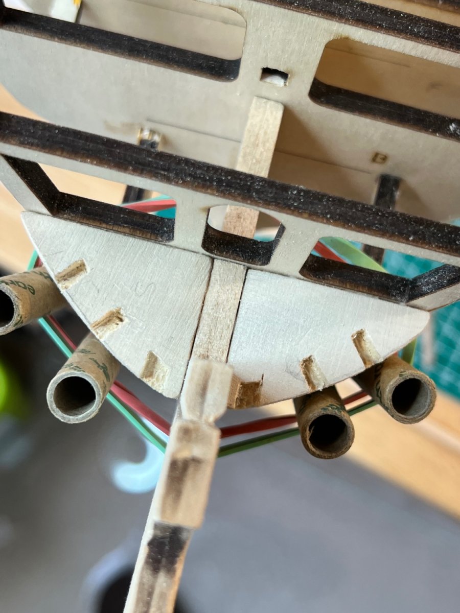
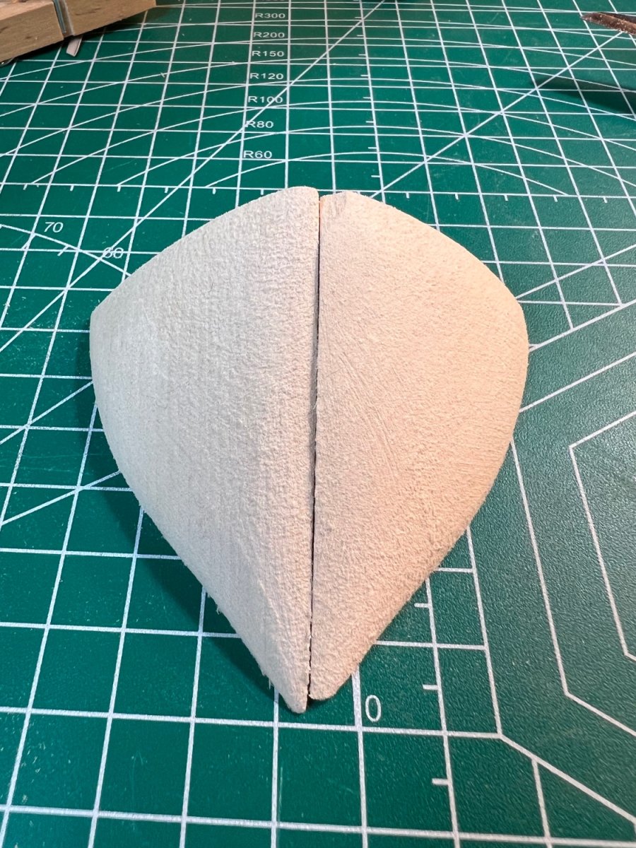
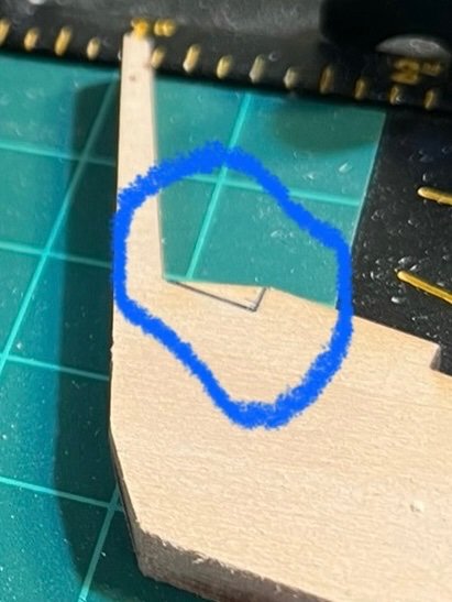
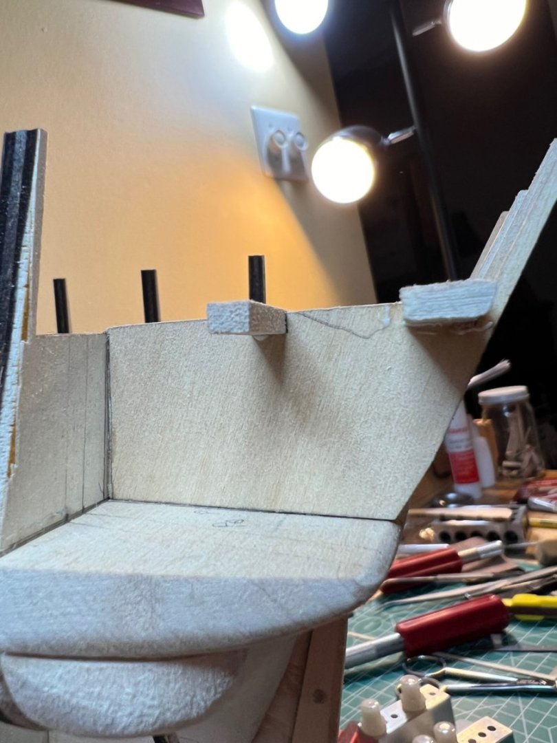
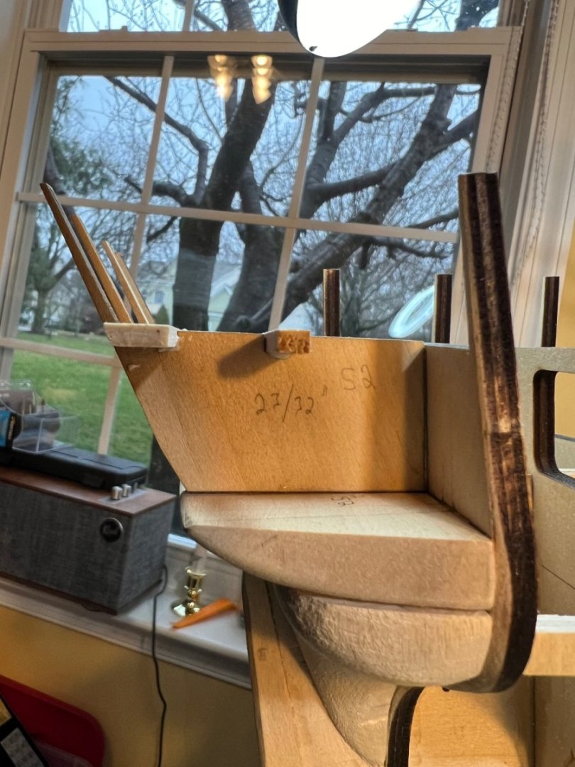
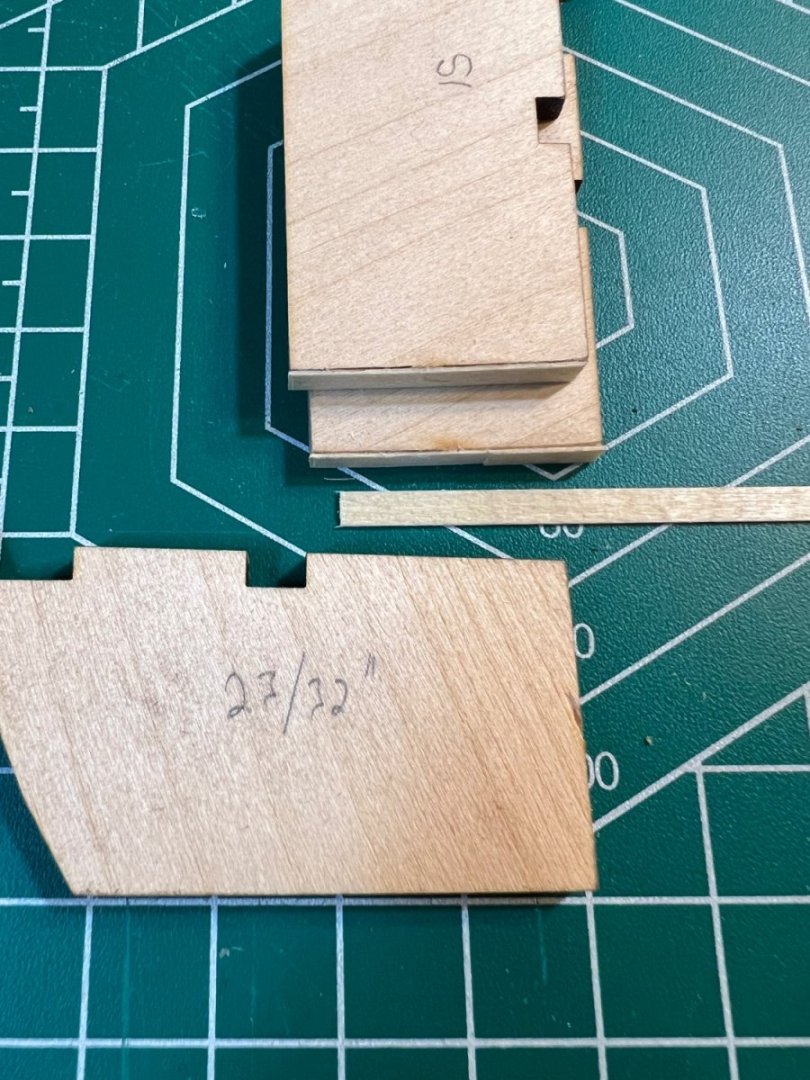
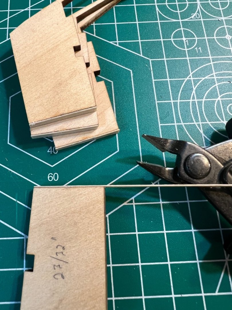
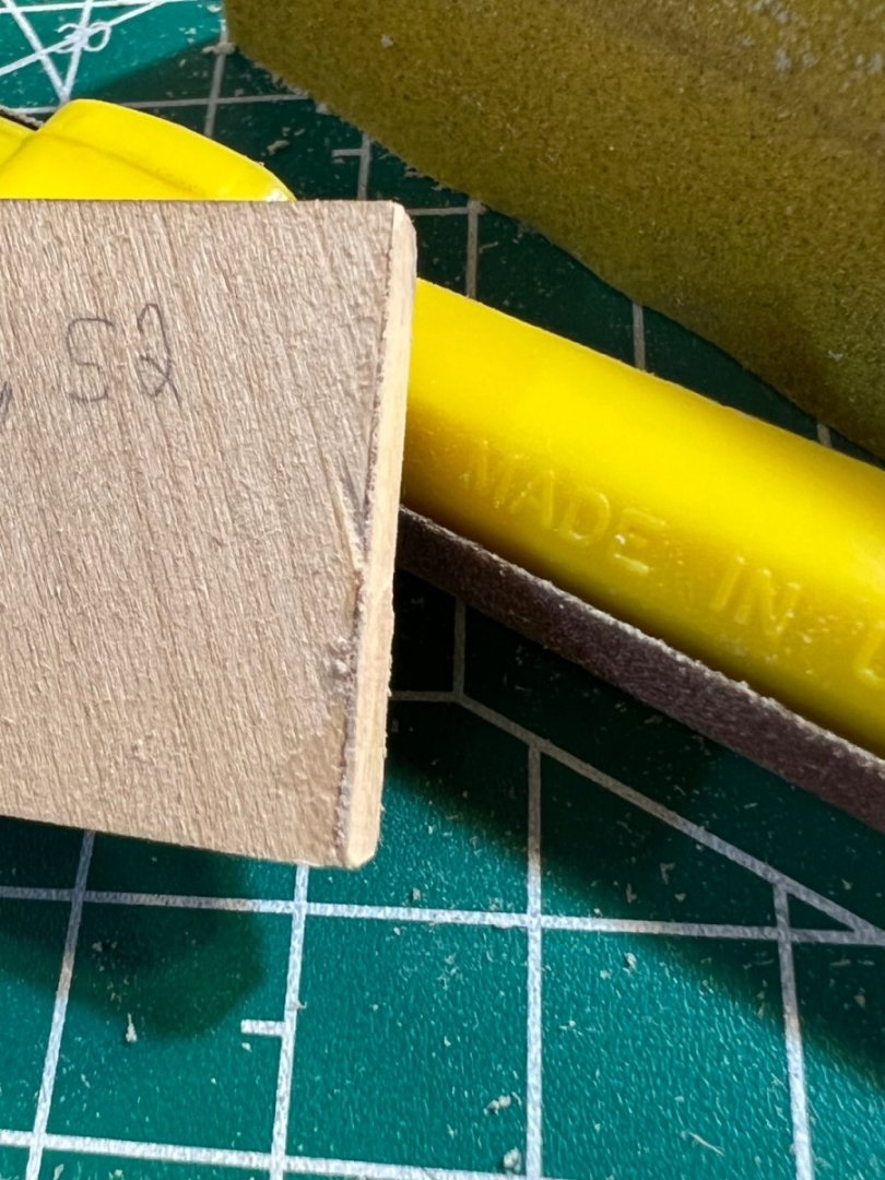
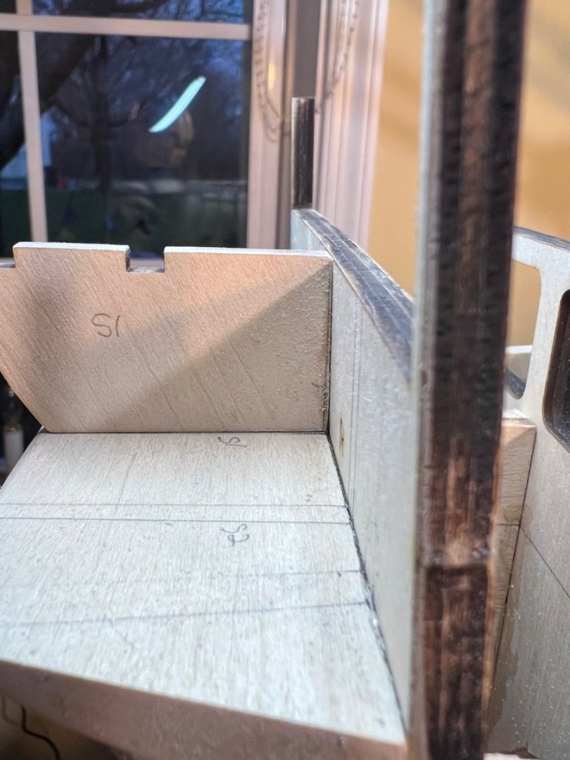
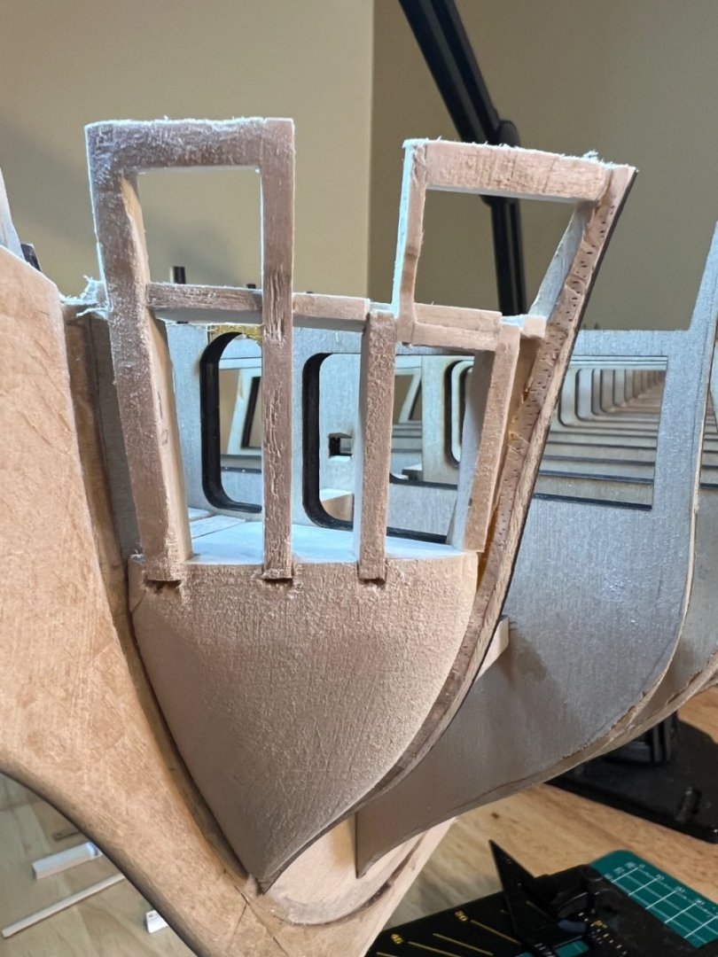
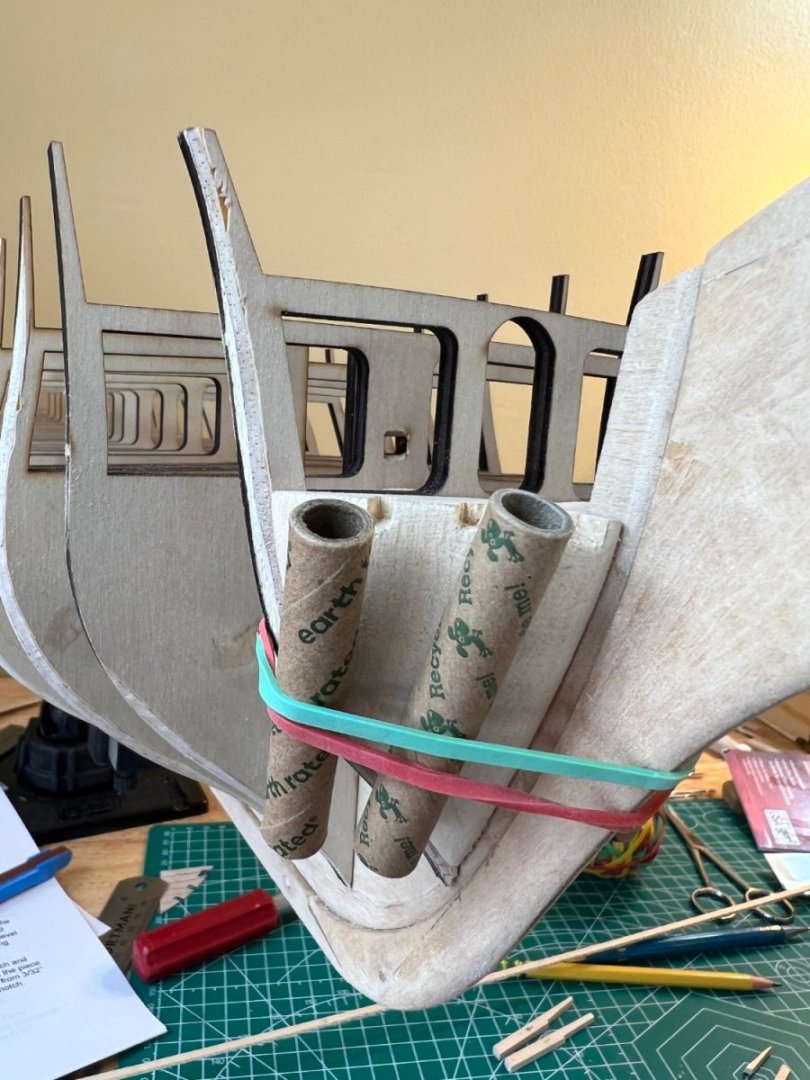
Stern Transom For some reason, I’ve really been looking forward to this section. Perhaps because the stern of the Constitution is pretty darn cool and I’ve admired it and the ship for my entire life. For those using the practicum - ignore the section that says something about adding an 1/8” to the back of the transom frames (section 2.2, Pg 17). It will send you on a snipe hunt (it was something likely relating to a mis-step Bob encountered and later fixed). I first transferred the frame template from plan sheet #2. You will quickly see that the outermost frame lines will not work and will need to be addressed later. I cleaned up my frames with fine grit sanding, and marked on the counter, the necessary 1 1/16” between the frames closest to the centerline and 23/32” between the next outer frame, as advised in the practicum. 23/32” isn’t a measurement I’m used to so I converted it to 11/16ths (I think). When sanding the char from the frames, be sure not to destroy the “knuckles” on the backside, bottom of the frames - or reduce the frame size. My counter and bulkhead R were a little less square than I realized, resulting in a slight gap when fitting the frames. I was concerned that sanding the frames to compensate would reduce their size. I solved the problem by utilizing some ultra thin strips of decking planks leftover from my Swift build. One was not enough, so I added a second segment on the lower 1/4 of the frame and sanded to fit. I added pictures to show the initial gap and the subsequent fix. I used WeldBond, applying a bit early so it would be sticky and moveable during placement. I then positioned the frames and measured. I was off a fraction, so moved outside the line to stick with the true measurement, rather than the lines transferred from the plans - as directed by Mr. Hunt. To hold down the glued frames, I borrowed a technique I saw in someone’s build log (I can’t recall who).


-
Jon - I do agree with your first statement, now. Though when I purchased the practicum - I thought it was perhaps more than it is. Like you - even with these incredible Constitution build logs (I also use yours often - thanks!!), I likely wouldn’t have begun without the practicum. I knew I was jumping into the deep end of the pool with this build, and I’m enjoying it, in no small part, b/c of the practicum. However at $100+, the practicum wasn’t cheap. My expectations where/are commensurate with the cost. Just like ordering steak 🙂 Peter - hope you don’t mind my friendly practicum discussion with Jon on your log - and great job on the planking! 🙂 Cheers!! -Andre
-
Hi Peter - I appreciate your detailed posting of the stern transom section. I am at this stage of my build now, and have performed my usual referencing of the Practicum, plans and builds. I too have the same issues with my "laser cut parts". That term makes me laugh - I'm not sure if the usage of "laser" is meant to impart a thought of "serious accuracy", but whatever software is running that laser needs a serious update. Bob H's Practicum typically has some sort of "WTF" head scratching moment. For this section, it came on Pg 17 of section 2.2 "Stern Transom Framework" @Para 2, second sentence, "Because you added 1/8" to the back side of transom frames 1...". Of course, there was no instruction to add 1/8" to the backside of anything... I feel okay bashing the practicum given the cost, and the general lack of editing (it appears at times that Bob just pressed save, then published it as is. I have found that many of the practicum's photos are nearly completely useless for the detail they are intended to display, these Conny builds have saved me numerous times). I'm impressed with your bevy of tools. My dad always tells me to use the right tool for the job. In this hobby, you often have to improvise, but the right tool is typically only a few days away!! Even so, I often find myself just eyeballing, shaping, eyeballing some more, redux, ponder, glue. Cheers! Andre
-
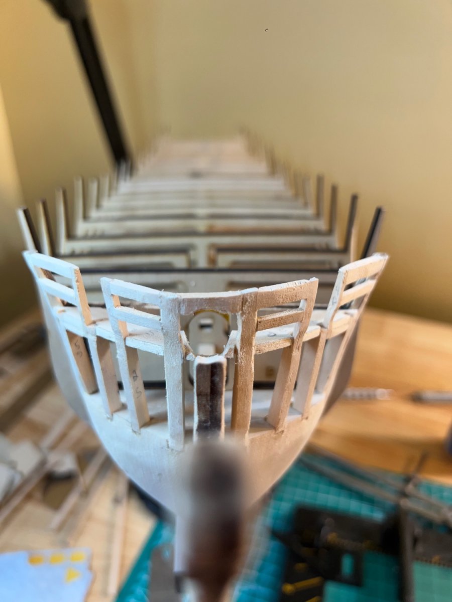
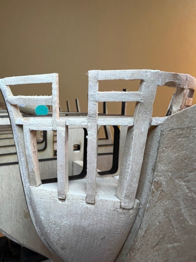
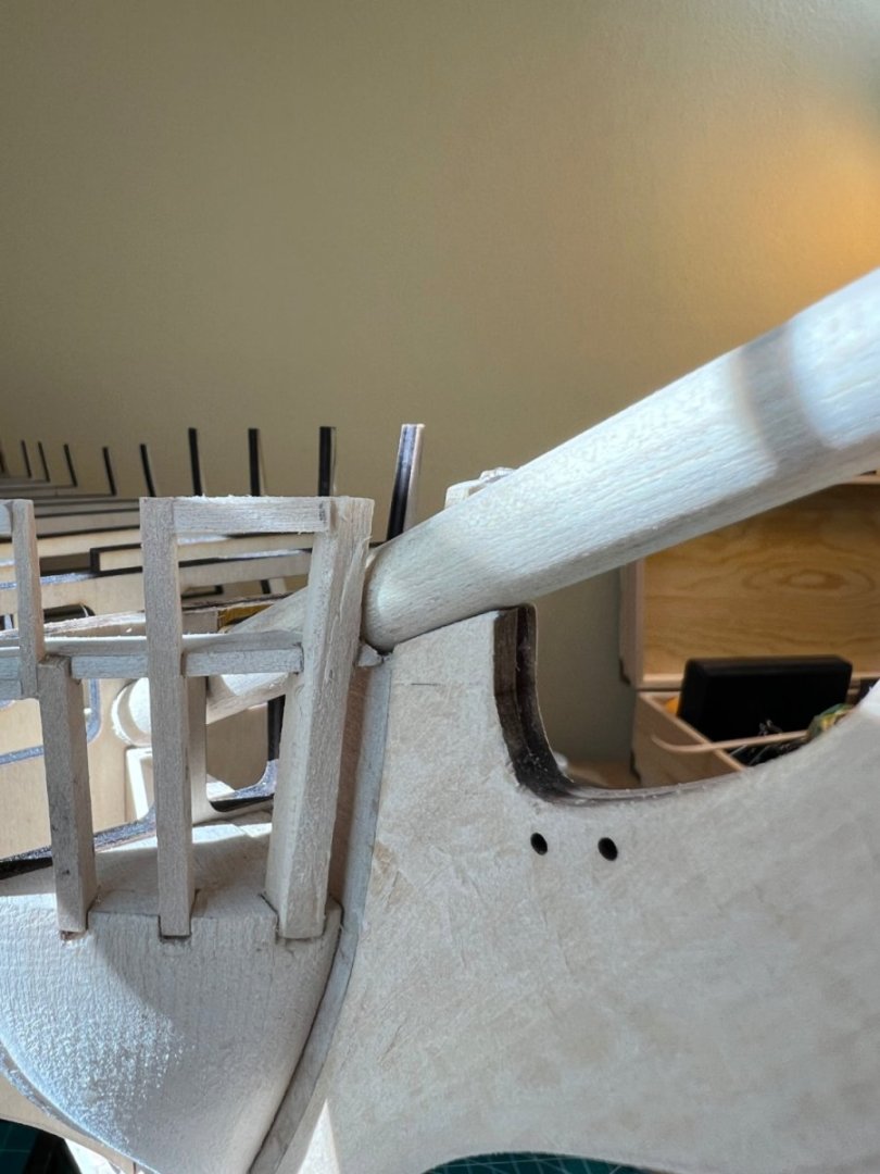
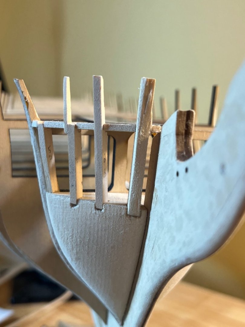
As mentioned- the beefed up Bow section with timbers added under the top rail supports - and the #1 timber connector over the top that also needed to be shaped to accept the bowsprit. As a wooden ship building novice - the bow section was a fairly intimidating build (thus, many pictures). For me, it was more challenging and fun than the bow and stern fillers. With sanding complete (for now), I can see areas that will need refinement and/or a shim to keep the planking fair. These areas are expected and are of little concern. The practicum states that additional bridal port framing will be addressed in the next Chapter (3). Most of the blogs have addressed that framing already. However- because my measurements ended up slightly off of the practicum’s recommended 9/16”, and the sheet plans make no mention of measurements here at all, I will wait to see what works when I get there. I’m looking forward to the stern transom!


-
I go to swim practice with my daughter and about halfway through a set of 400’s, I’ll think about the Conny and come up with a plan to solve whatever sticking point I’m at (or remember that I forgot to do something). I thought I was done with the bow framework - then decided (influenced by some other projects, including yours) that it looked a little flimsy and was in need of some shoring timbers. I also noted that I forgot to add the final timber connecting the port and starboard #1 timbers. This also included some sanding to fit the bowsprit. Yet another Proxxon device helped with that. I like your philosophy toward tools. I already have the digital calipers, but may still get the proportional dividers. If even just because they look well designed and I’d like to know how to use them. 🙂
-
Bow framework complete. Sanding to acceptable visual tolerances. Final touches to be addressed during planking. Proxxon micro sander was very helpful. In to the Stern Transom framework.

-
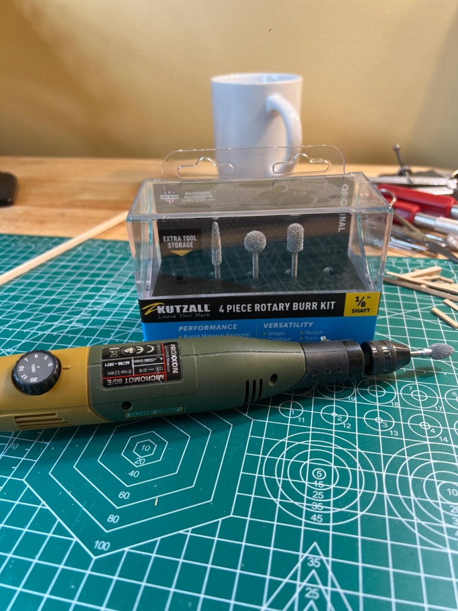
Rough Bow work completed. Will need sanding. I will eyeball it and detail the fairing later. I added slightly larger timbers (3/32”) for the port side top strengtheners, and added more between #3&5. Other build logs as well as pictures in the practicum show shaping for the bowsprit. A Proxxon tool and Kutzall Burr kit did the job. I’m looking forward to the stern transom framework.


-
I believe I have that same micro caliper - but I’m also a staunch believer in “no such thing as too many tools”! :-)
-
I was thinking that was a likely location for Hawesholes? If necessary I may just make it a closed hatch. I have to work on this between swim meets, practices, work and other life, so when I get bogged down for too long, I get impatient and have to move on. It is funny how much research I end up performing before I get to that point though. The starboard side bow framework was a bit of a headache - mainly because I spent a lot of time making the parts precise from the plans, but still, nothing lined up very well and a lot of fudging was to be had. Now that it's complete, the Port side is moving along smoothly. Lessons learned are getting put to good use 🙂 I noticed your spreadsheet - that was some impressive detail. I'll likely do the same when I get there. I was thinking about getting some micro-calipers, or possibly the proportional divider (Micromark - #14129) for planking. Any suggestions on a must have instrument/tool for that future effort? Cheers! Andre
-
Added the stiffeners between timbers 1&2, and 4 & Bkd A. I had to square the edge of Blkd A slightly and shape both stiffeners. I will sand smooth when dry.
-
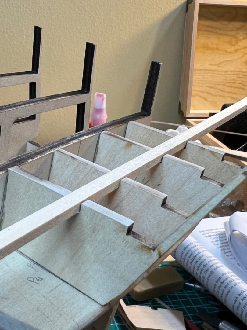
After reviewing 4-5 build logs and the ship plans, I can’t see a plausible reason for the 9/16” precision measurement on the 3-5 timbers. At this point - close is good enough. I’ll deal with consequences later. That #4 timber sure is a skinny fellow. The spar deck framing fits flush with the timbers and provides a flush surface with a plank (metal ruler) over bulwarks A-D, and the timbers are reasonably well positioned for planking. Time to glue. I will sand smooth when dry.
-
Thanks for that - I do think I’m spending more time than necessary fairing as I go. At this point I’m just eyeballing it a bit. I’m a bit caught up now with the Bow framework. I have achieved what looks like decent alignment with timbers 1-5. However the practicum says there should be 9/16” between timbers 3&5, and “exactly” 11/32 between 2&3. It will take some creative shaping. Since the 3-5 spacing forms the bridal port - I’m assuming it’s not the place to just be in the ballpark. As for the tools… it’s amazing what you can accomplish with a Central Machinery Belt & Disk sander! But it’s tough to do the delicate work on there. The fillers took flight across the garage a few times.
-
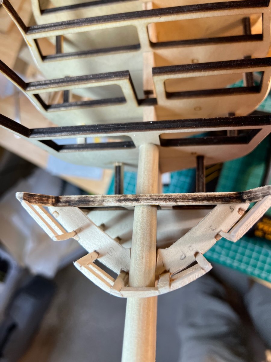
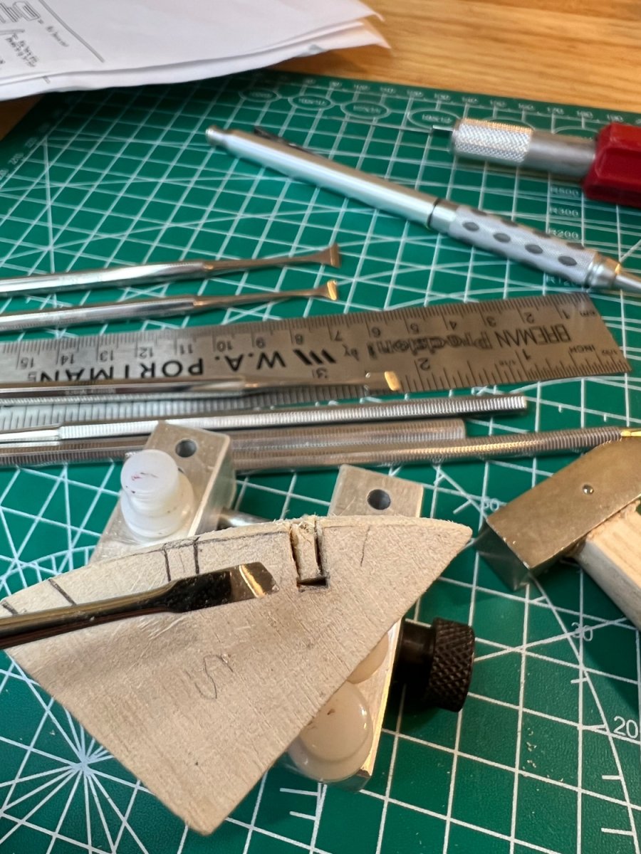
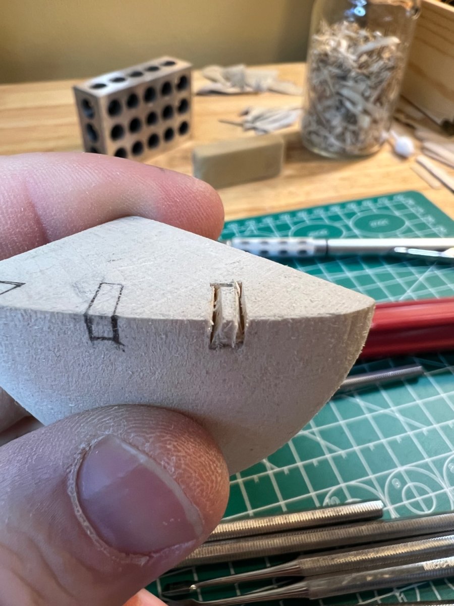
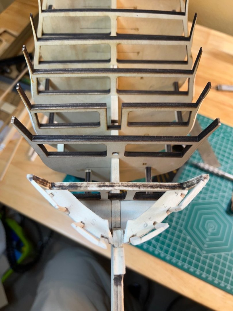
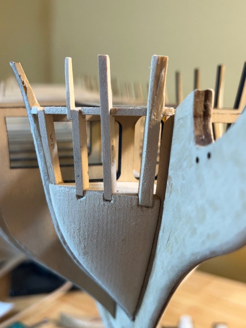
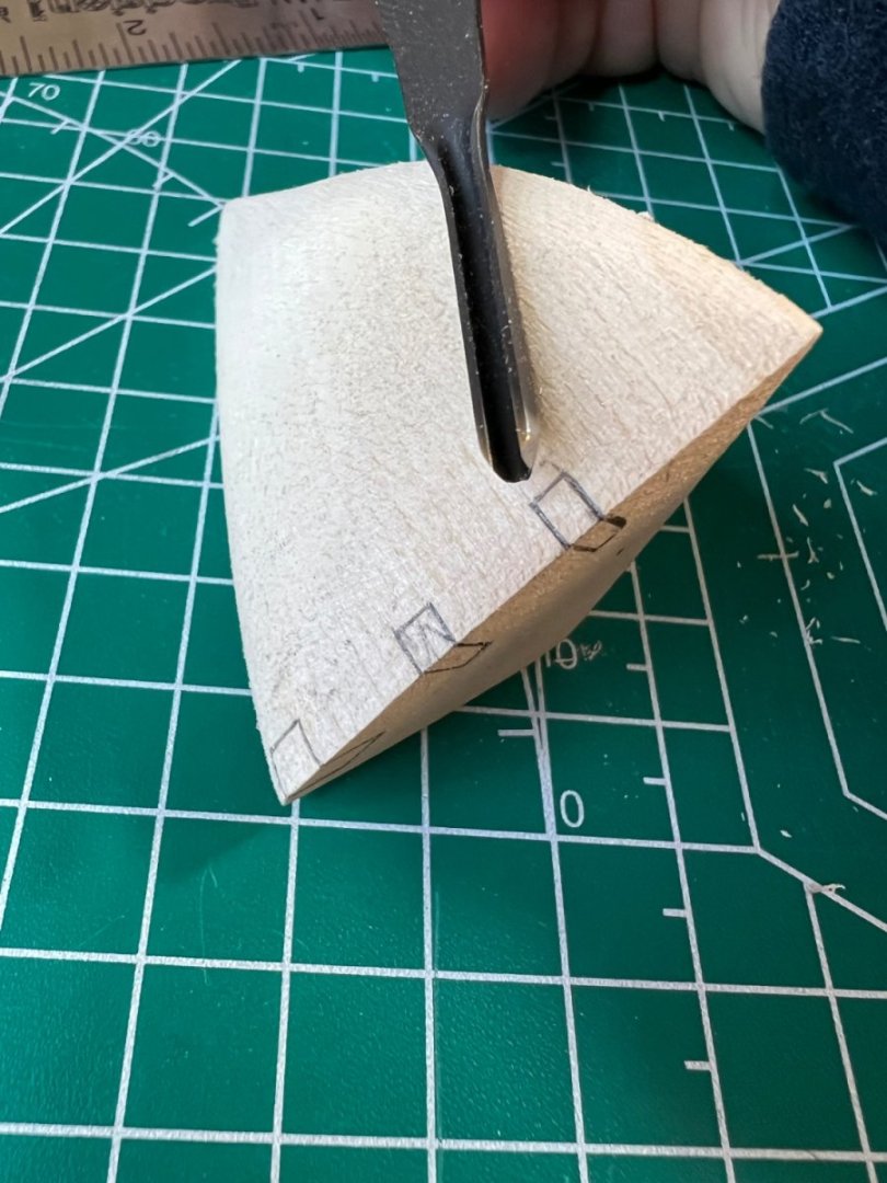
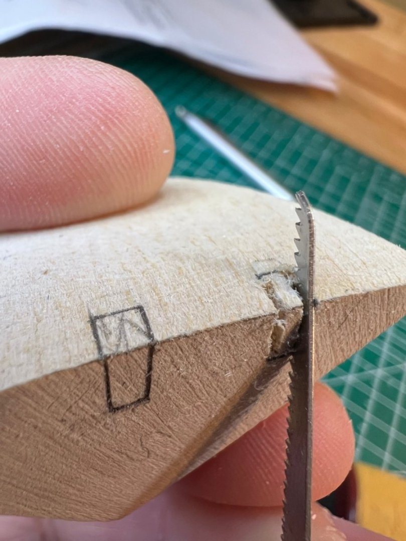
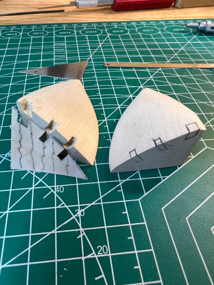
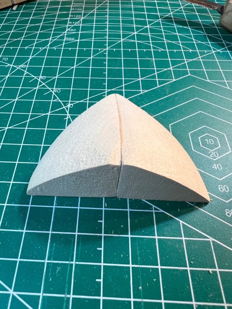
I cut the notches into the bow fillers. It was a good decision to cut the notches prior to the fillers being permanently attached. Oddly, it was both easier and harder than I thought it would be. The cutting was manageable but I needed about 10 different angles to get to complete the job - angles I couldn't have achieved if the fillers were attached. To cut the notches, I drew the outline, then used a small saw to cut the side lines, from front to back, also cutting material away between the two edge cuts. I then used a new #11 Exacto cutting blade, some fine (sharp!) wood cutting tools, and a set of micro chisels from Micromark. The block won't come out as a solid unit, so you need to pick away at it. My intent was to create a flat surface with 90 degree angled corners. The wood is far too fibrous for this, and it seems I was going against the grain. As happens with this hobby, after spending a long time picking away at the notches, I found that a pursuit of perfection was becoming the enemy of good (or good enough). With the notches completed, I could see no reason to keep from attaching the bow fillers. It's funny how it seems such a big decision, but after spending so much time shaping them, that's not surprising. I glued the fillers with Weld Bond.


-
Thanks Peter - the pictures were helpful.
-
The bow fillers are done - at least I’m done with them. They will require additional attention when fairing. I found myself really wanting to keep a nice rounded curve shape, but in reality, the proper shape is much much less of a pronounced curve than you may expect. I have to decide now whether to glue them on now as the practicum instructs. I’m leaning hard toward cutting the Knighthead support notches first. I have a feeling that those cuts will be harder than they look.


-
Geoff - you are so right! I lost count at how many times I felt it was “good enough”, then came back for more. I did a cursory test with a bent plank and it’s close. I don’t want to cut anymore. I’d rather spot sand now then to try and reach perfection before I plank. The prospect of fairing this ship is a little intimidating. I’m more anxious to plank than I am to rig - and this ship has 400yards of rigging!