Frank L.
-
Posts
36 -
Joined
-
Last visited
-
 GrandpaPhil reacted to a post in a topic:
Emma C Berry by Frank L. - Model Shipways - 3/8"= 1'-0"
GrandpaPhil reacted to a post in a topic:
Emma C Berry by Frank L. - Model Shipways - 3/8"= 1'-0"
-
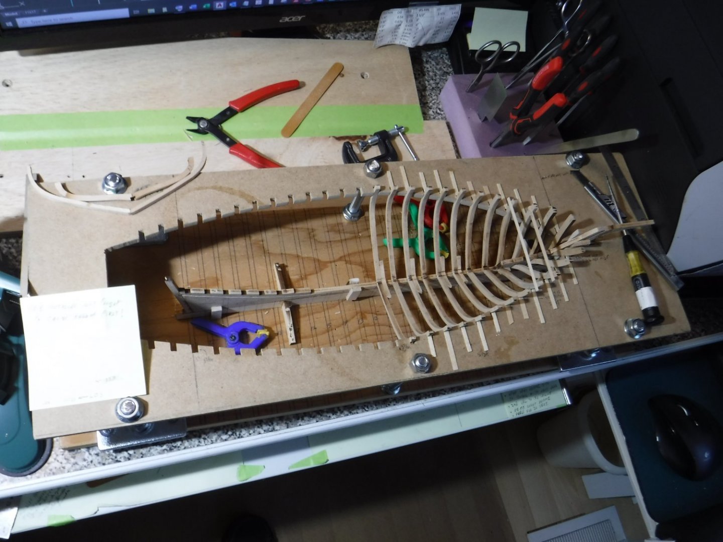
Clamp boards are fully installed now. If I had to do it over again, I would install the spacer batten strips with the hull in the jig, but the clamps are better installed with the hull taken out of the jig.
-
The 3/4'' wide binder clips from Staples are fantastic for model ship building. They open to about 1/4'' - maybe 5/16.'' I used them to re-glue most of the frames to the clamp board. The frames popped loose when I detached the batten spacer that was 'tacked' in place with glue.
-
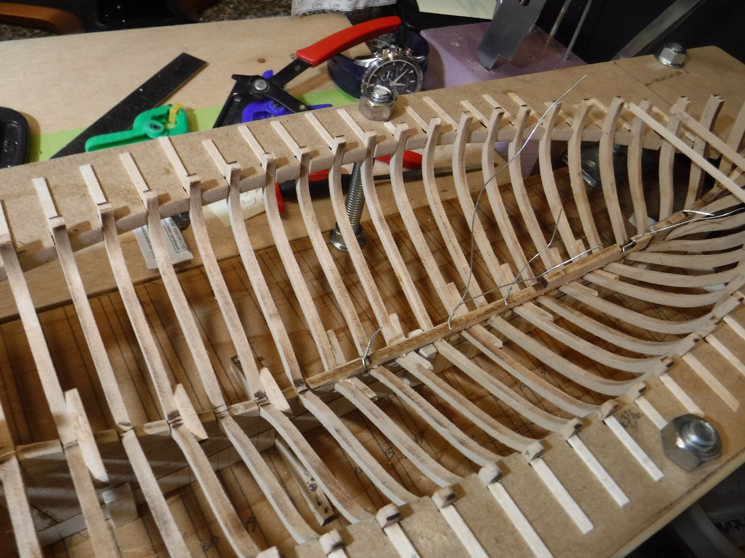
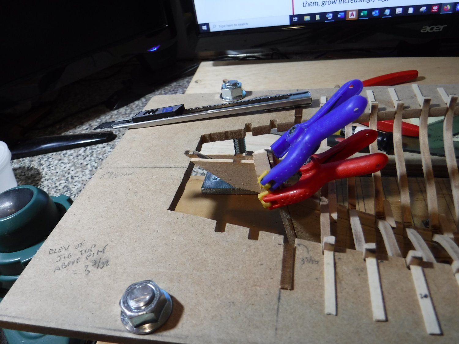
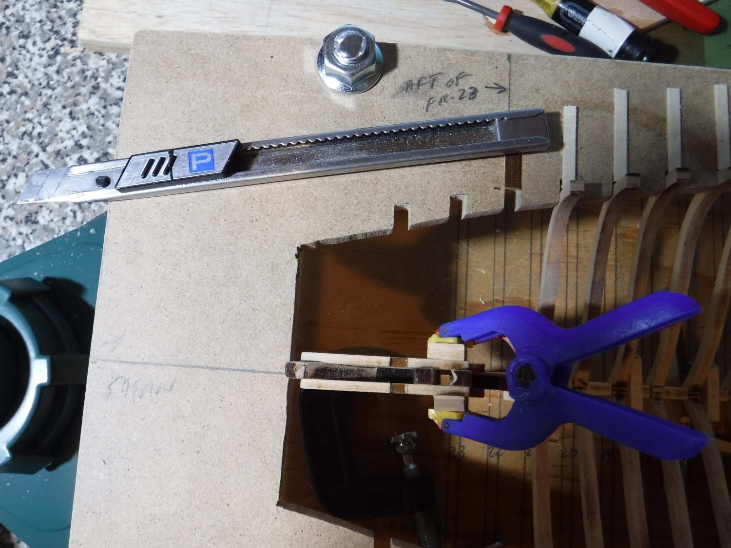
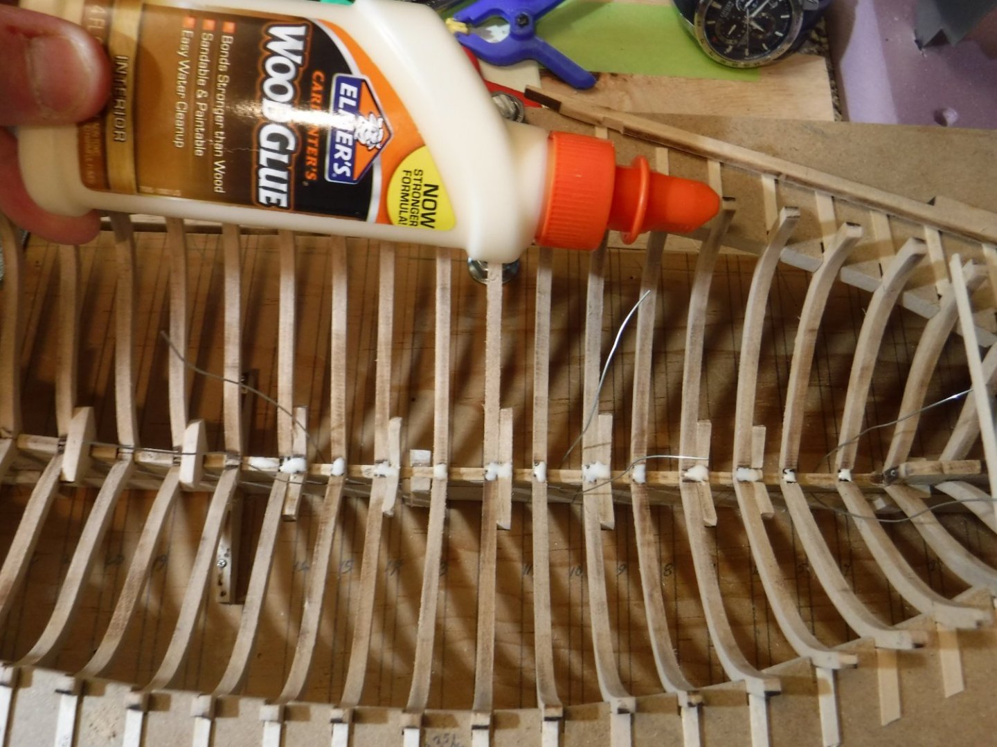
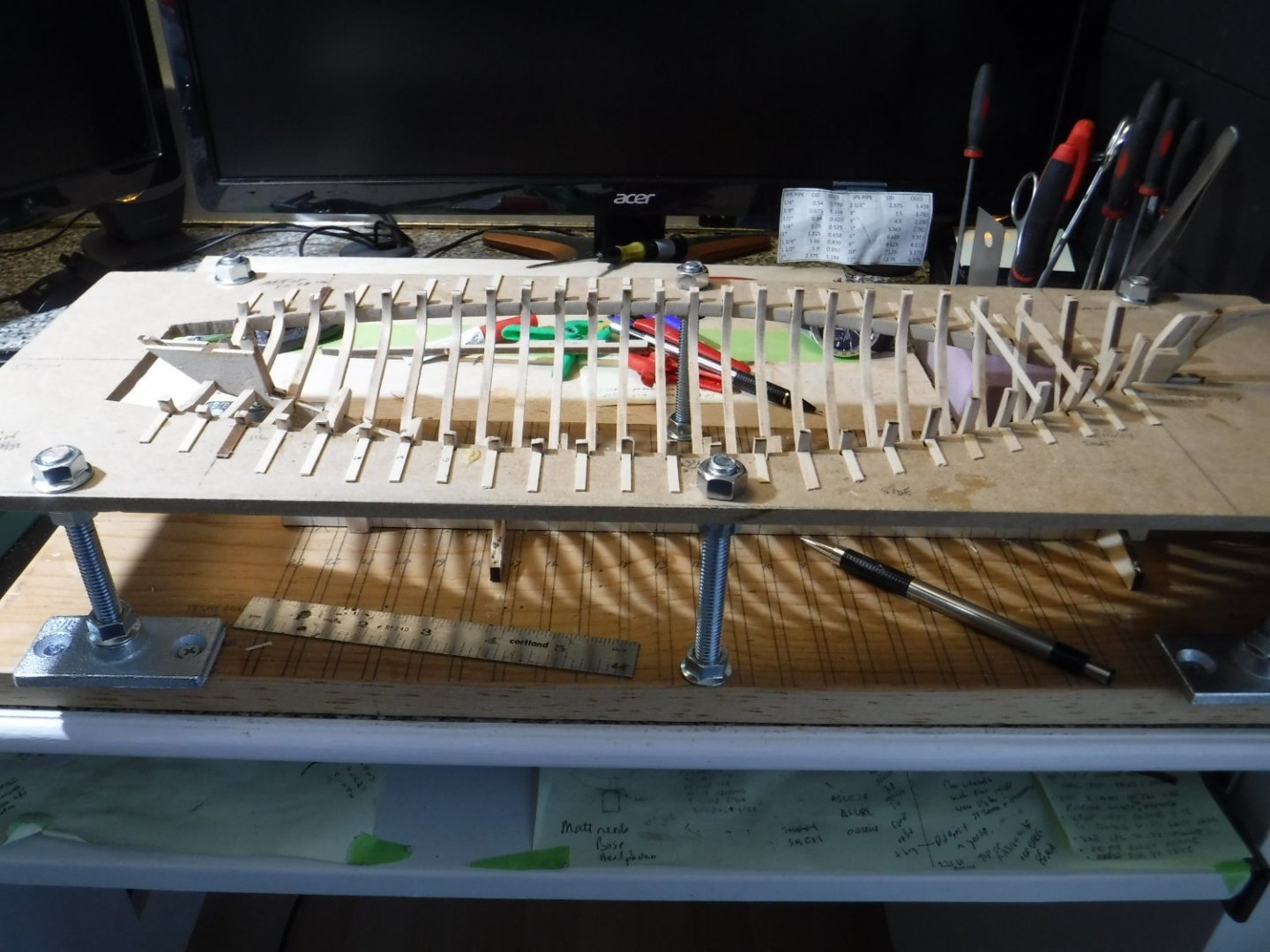
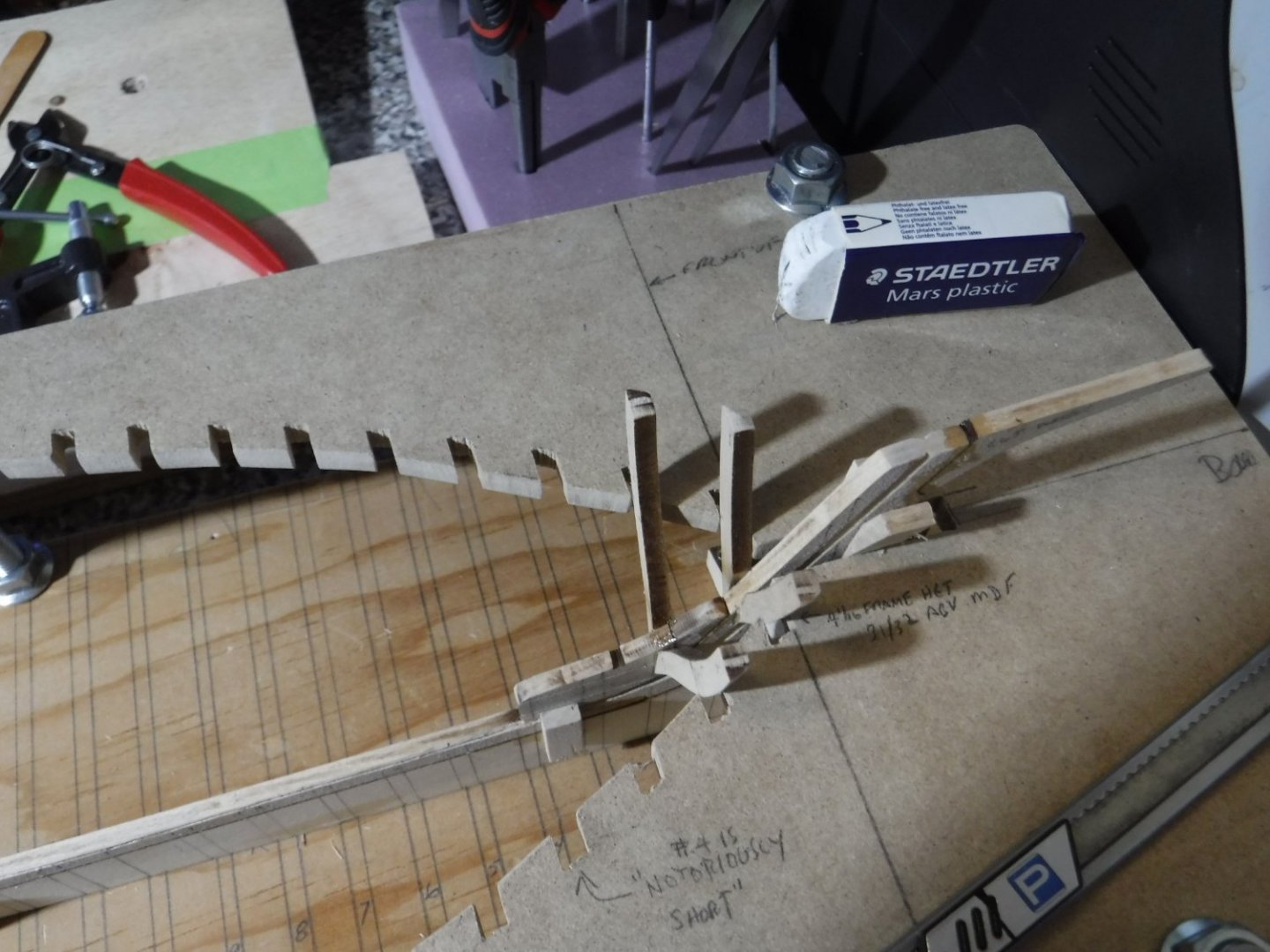
My temporary spacer batten strips for clamp placement [see figure 1-12 in the instruction manual] are now in place and attached to each frame with glue. (I plan to separate them later with a zona saw or razor knife) But I see the frame tops are not in line with each other. The frames should have come extra long so we could trim each one down to the top of the batten. Just like when you build a wooden deck out of 2x6's, you run them extra-long, snap a chalk line and trim them perfectly flush. And yes, frame 4 is especially short, as noted by other modellers. I had to elongate it with a half-lapped extension using scrap from the laser sheet that the frame was taken from. It took quite a while to make it fit well. Maybe a simple butt joint would have sufficed. But I wanted to maximize glue surface for strength.
-
As I tack the temporary clamp spacer board to the frames, I find it necessary to release the frames from their battens to which they too, were temporarily tacked. Battens are the little strips of wood used to prevent any motion of the frames perpendicular to the keel during the framing process. They were adhered to the jig surface with a tiny amount of glue and the the frames with another tiny amount of glue. The notches in the jig prevented any fore-aft motion of the frames.
-
FYI The PDF template mentioned above is modified to better grab the first few frames.
-
yvesvidal reacted to a post in a topic:
Emma C Berry by Frank L. - Model Shipways - 3/8"= 1'-0"
-
Here is my template. But you need to bring it to Staples if you do not have access to a printer that handles ledger size prints. EMMA C.BERRY jig template rev. 4-19-22.pdf
-
mek reacted to a post in a topic:
Emma C Berry by Frank L. - Model Shipways - 3/8"= 1'-0"
-
reklein reacted to a post in a topic:
Emma C Berry by Frank L. - Model Shipways - 3/8"= 1'-0"
-
reklein reacted to a post in a topic:
Emma C Berry by Frank L. - Model Shipways - 3/8"= 1'-0"
-
ccoyle reacted to a post in a topic:
Emma C Berry by Frank L. - Model Shipways - 3/8"= 1'-0"
-
ccoyle reacted to a post in a topic:
Emma C Berry by Frank L. - Model Shipways - 3/8"= 1'-0"
-
yvesvidal reacted to a post in a topic:
Emma C Berry by Frank L. - Model Shipways - 3/8"= 1'-0"
-
yvesvidal reacted to a post in a topic:
Emma C Berry by Frank L. - Model Shipways - 3/8"= 1'-0"
-
yvesvidal reacted to a post in a topic:
Emma C Berry by Frank L. - Model Shipways - 3/8"= 1'-0"
-
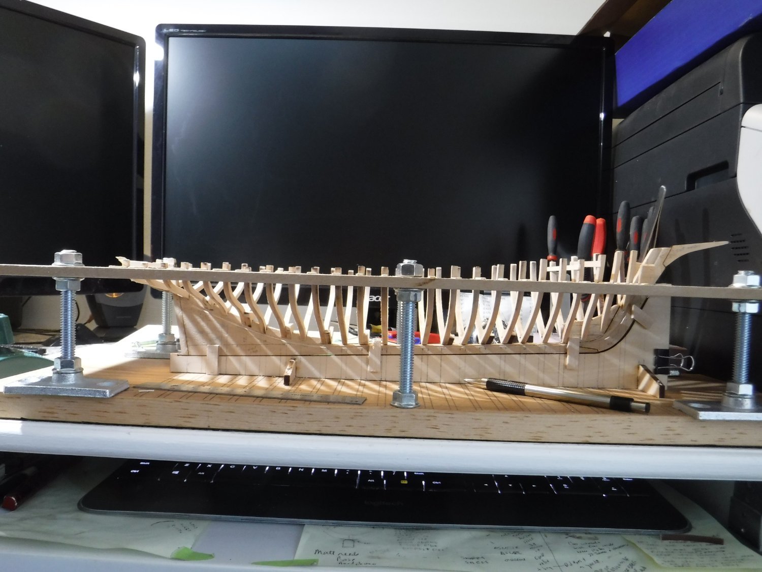
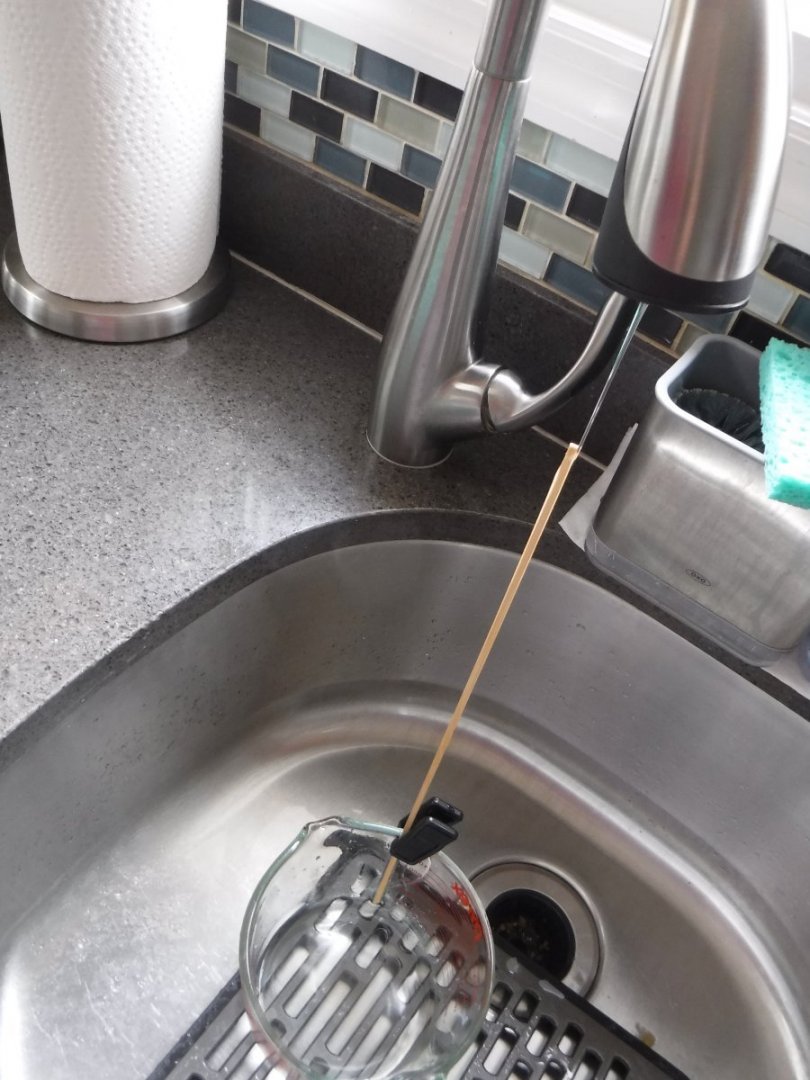
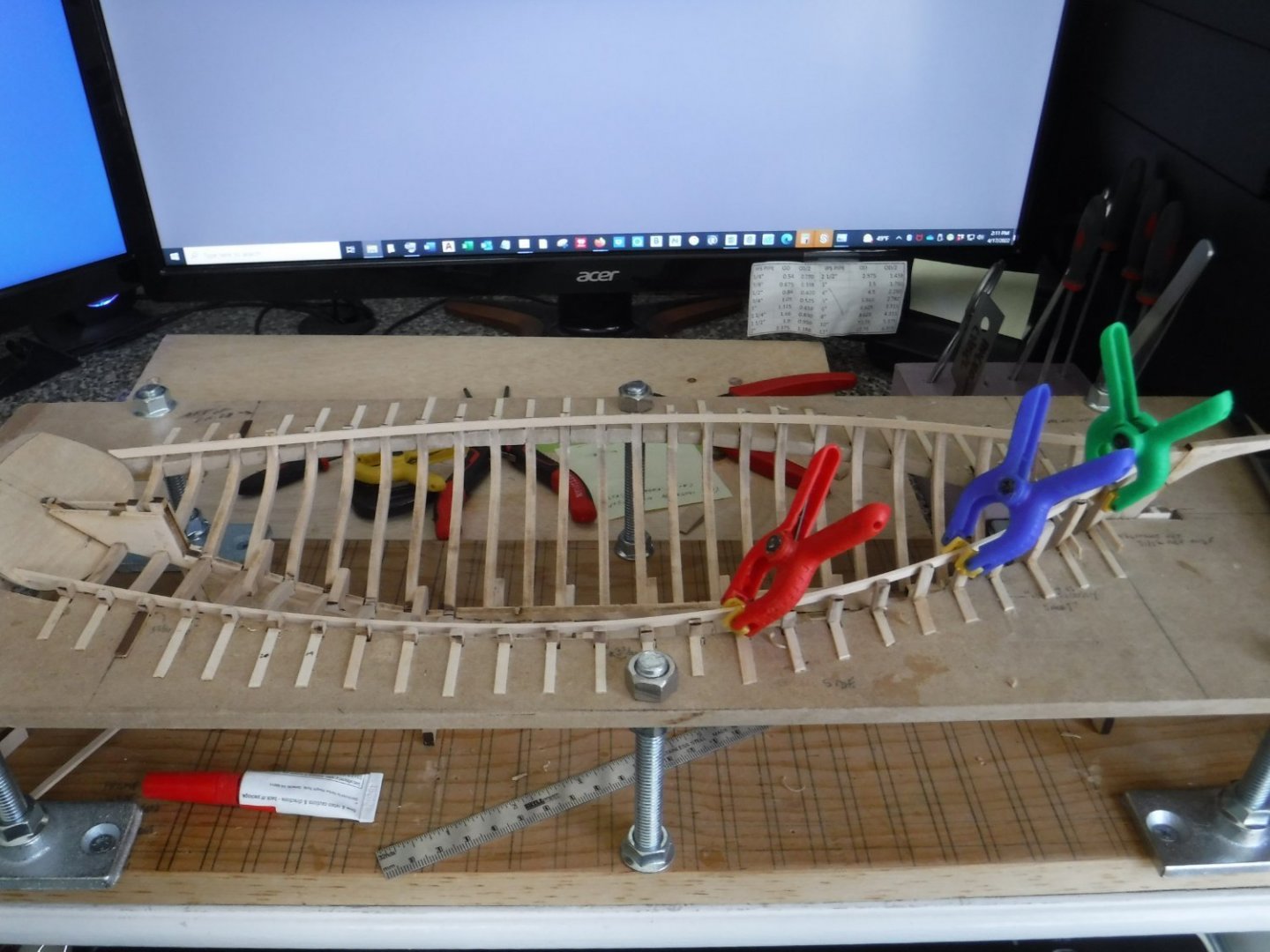
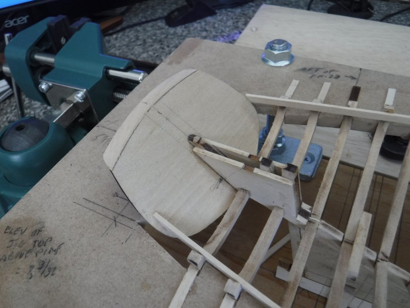
Installation of temporary batten to help accurately locate the hull clamp board. Some carving of keel-side bevels of the the first few frames was needed for glue contact area of both the temporary batten as and the forthcoming hull clamp board was needed. Dabs of PVA glue was applied to the frames before setting the battens in place with spring clamps. I pre-bent the battens by running a trickle of hot water down their length in the sink in order to soften them. Transom was installed before the batten work was done. The trick with the transom elevation is aligning its bottom bevel with the 'plane' of the frame's bevels.
-
Had a hard time coming up with a method for clamping the keelson unit while the PVA glue cured. I ended up using wire. There was a lot of sanding/carving/shaping involved with getting decent contact areas for the glue.

-
Clamping the glued-up rudder box to the keel. See Andrew Bodge's ECB build log for details I contributed as to the proper positioning of this assembly.


-
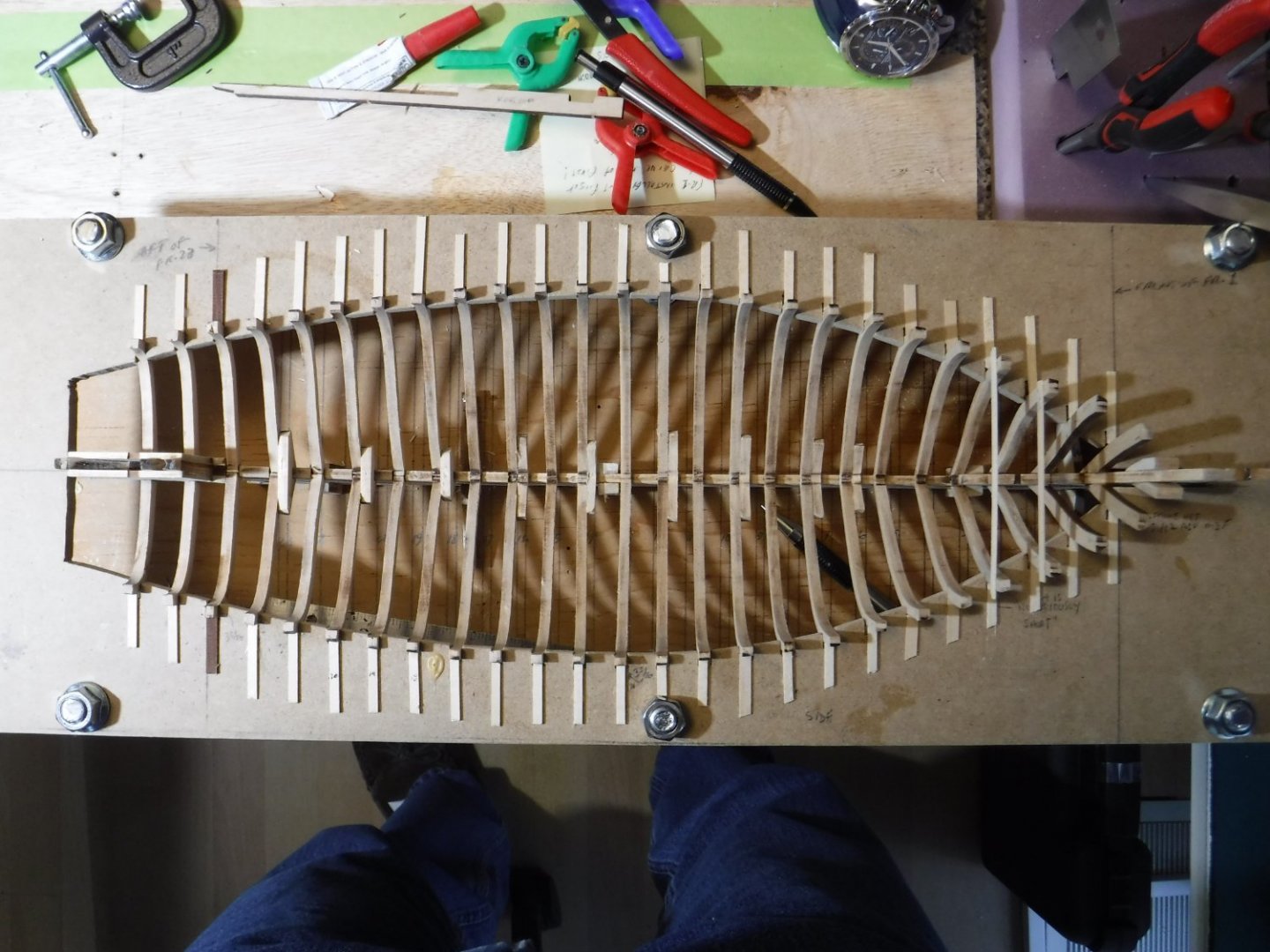
All frames are in place.

-
Frames 4 thru 23 were pre-assembled on a flat surface marked with frame width measured from blueprints.
-
Frames 1 thru 12 in place. Jig notch depth improved.
-
Frames 2 and 3 are in place. Jig notches just barely caught these frames. It was not easy designing the jig's cutout. I feel lucky it worked out OK.

-
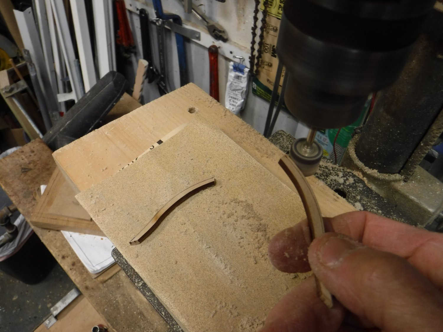
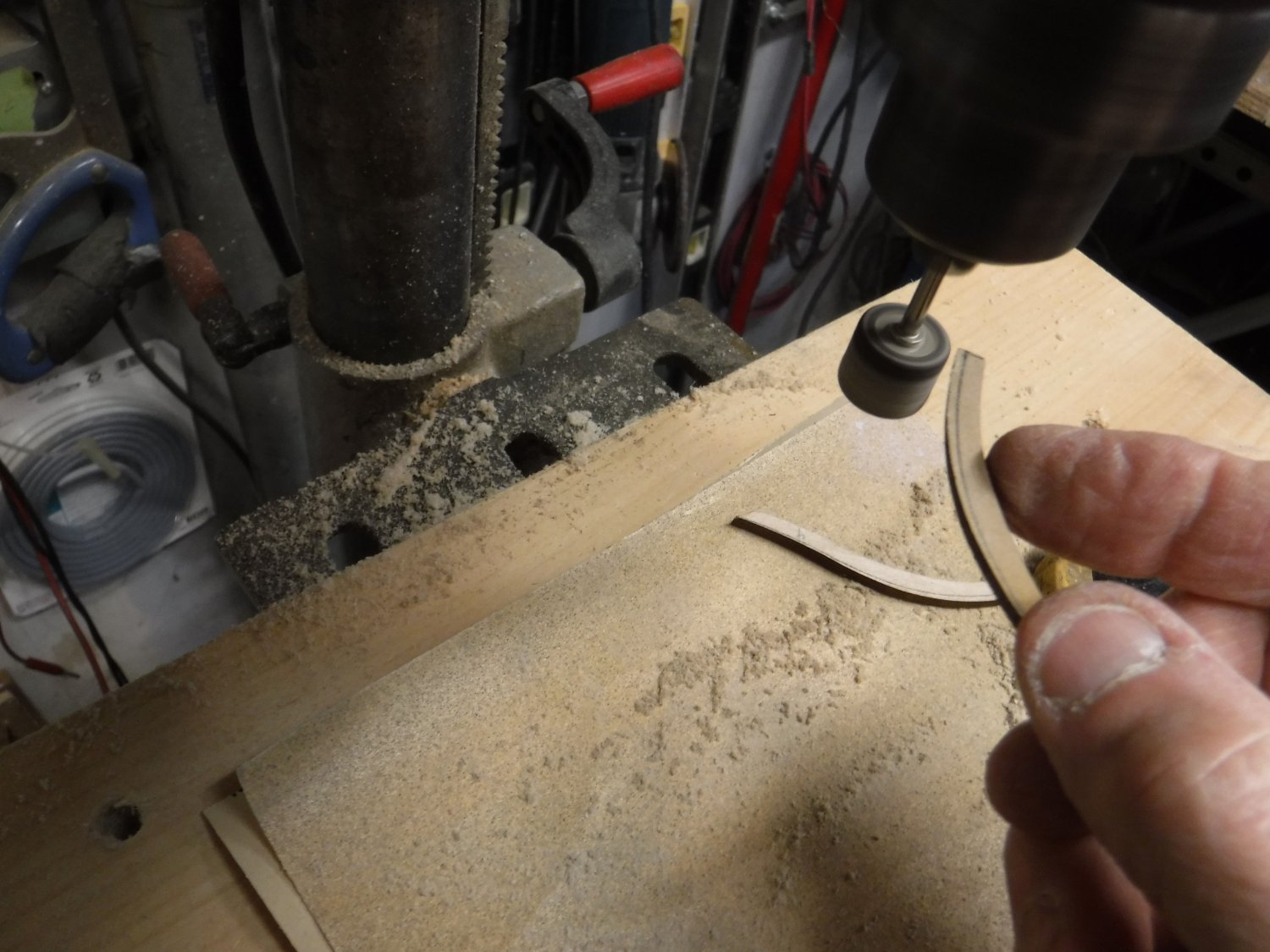
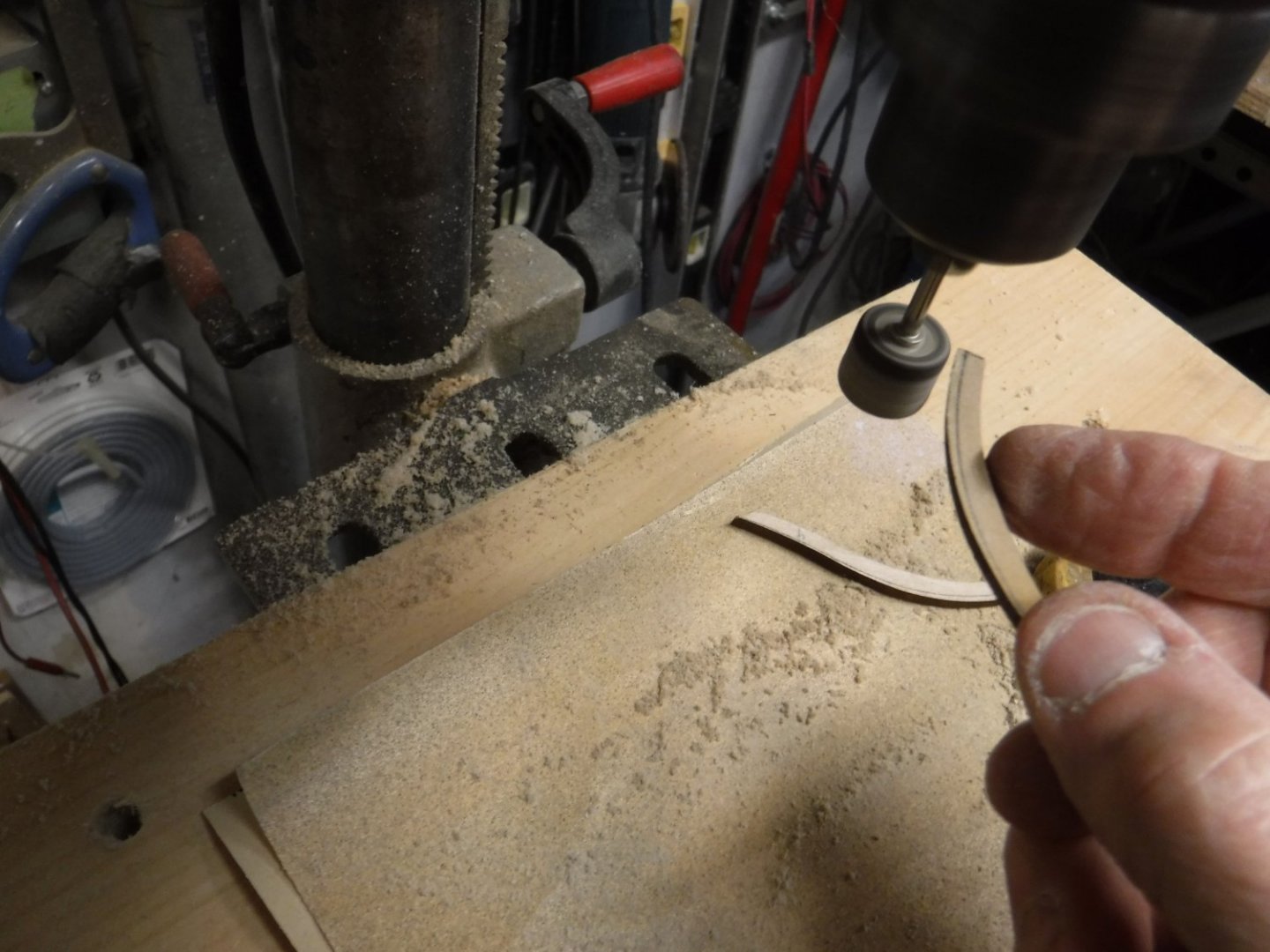
To create the frame bevels, I mounted a Dremel sanding drum into a drill press. Using a hobby knife seemed too risky. Sanding is easier to control. It is also easy to remove char with this setup.

-
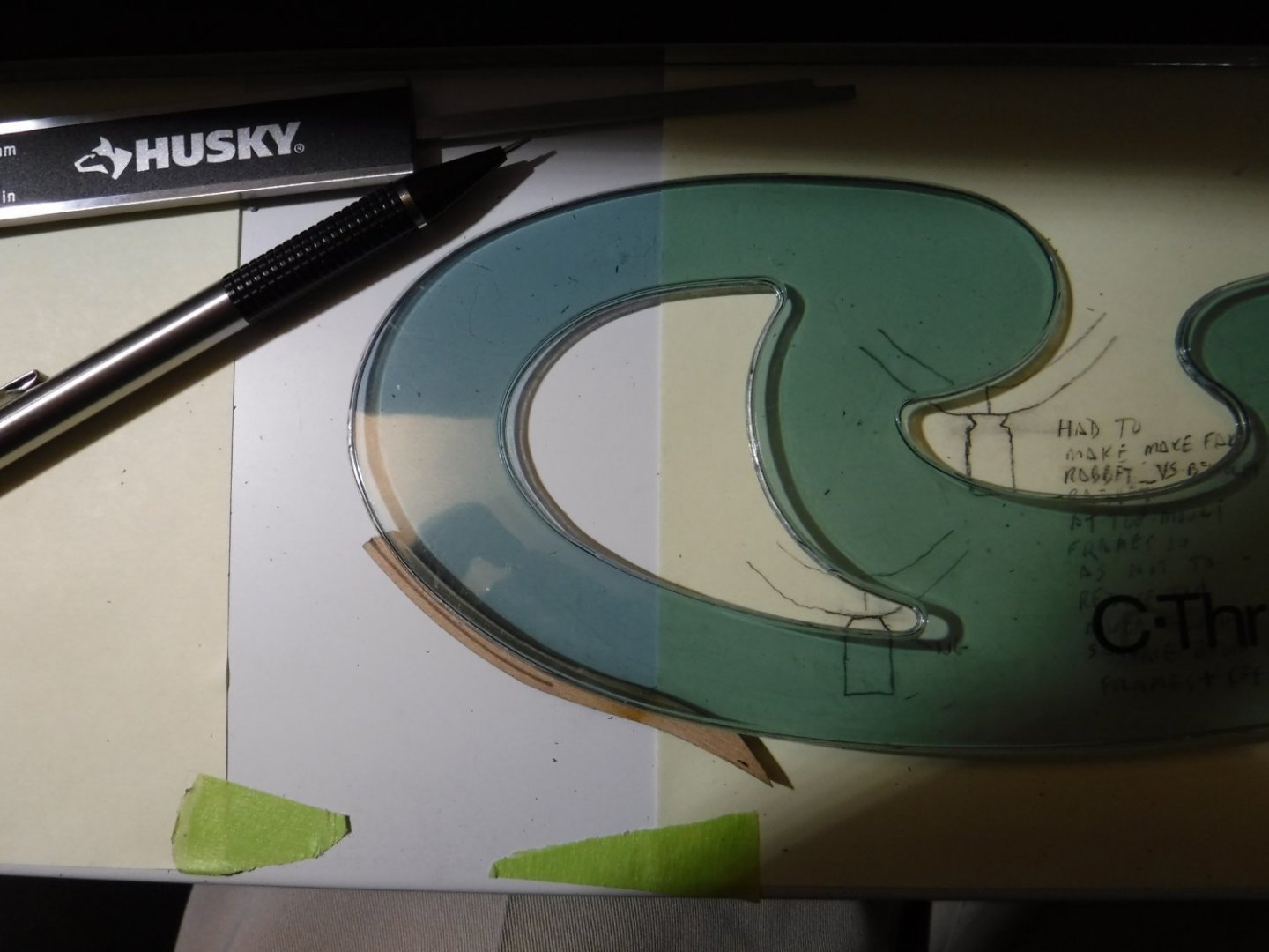
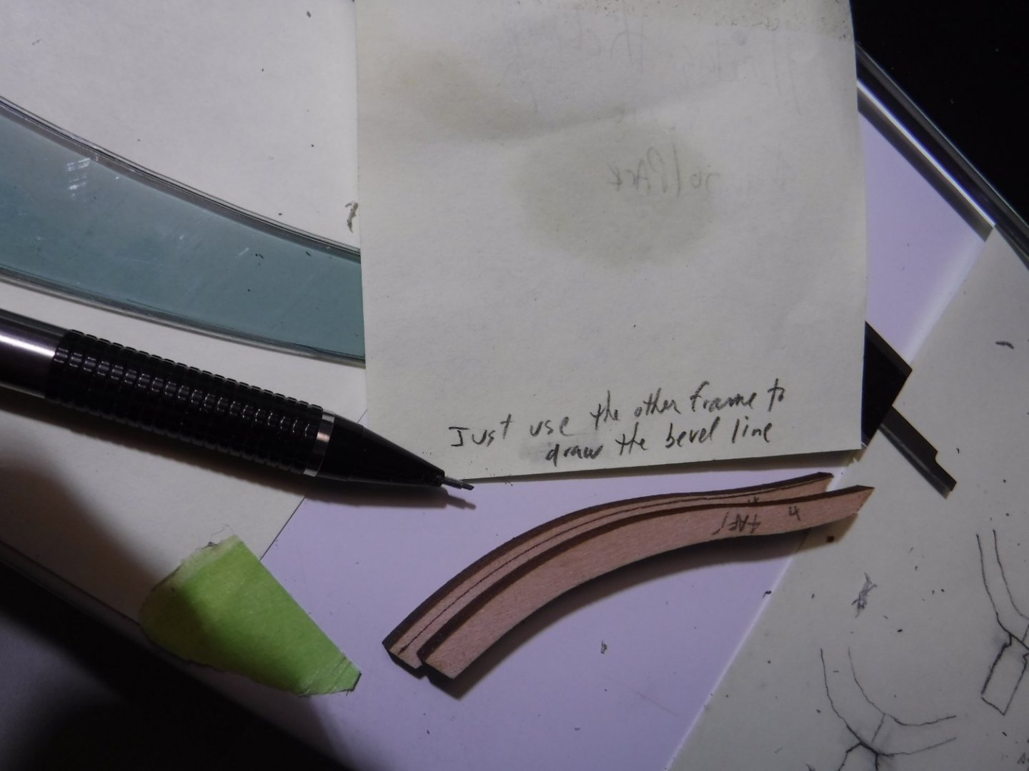
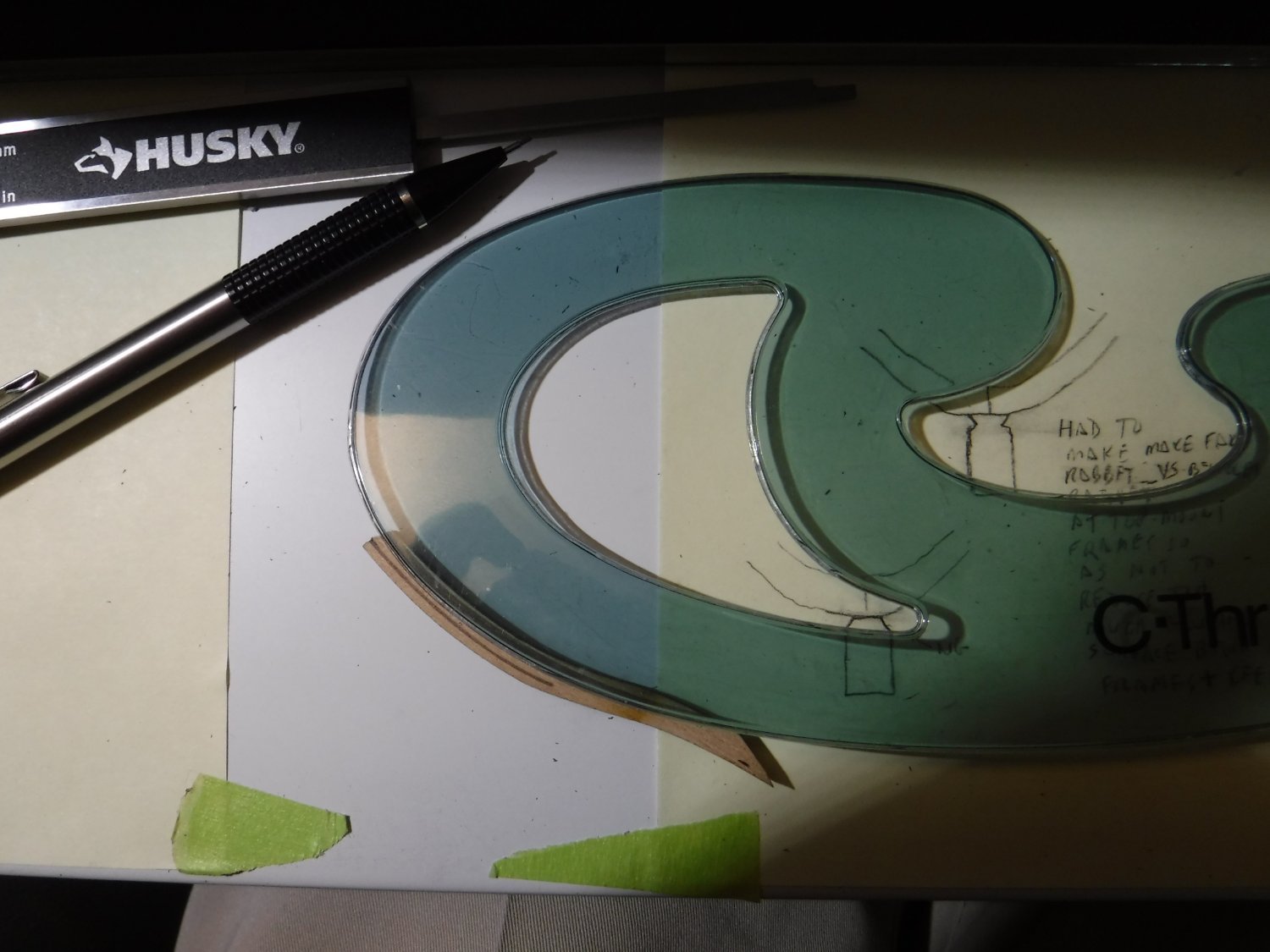
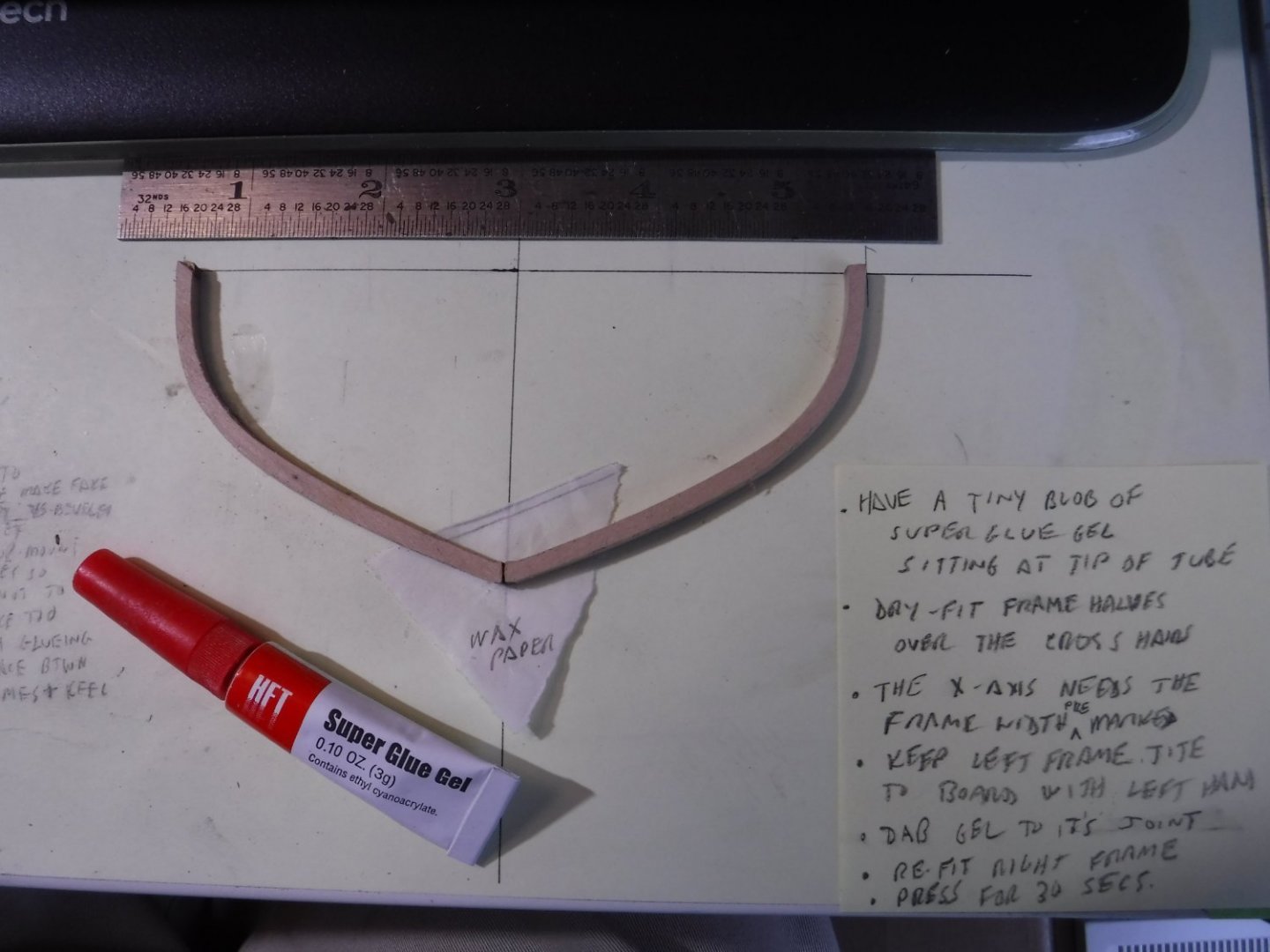
To mark the frame's bevel lines, I started using a french curve. But it was smarter to use the port side frame as a guide to mark the starboard frame and vise-versa. Just eyeball the location from the blueprint. I opted not to produce the keel-side bevels. We will see if I come to regret that later.