HOLIDAY DONATION DRIVE - SUPPORT MSW - DO YOUR PART TO KEEP THIS GREAT FORUM GOING! (Only 20 donations so far - C'mon guys!)
×


mark.bukovich
-
Posts
95 -
Joined
-
Last visited
Content Type
Profiles
Forums
Gallery
Events
Everything posted by mark.bukovich
-
Good idea using the strings from masks! I'll have to remember that
- 61 replies
-
- 1
-

-
- Lowell Grand Banks Dory
- Model Shipways
- (and 1 more)
-
Looking great! I've had an interest in this kit; it's helpful to see it come together
- 90 replies
-
- 1
-
-
- Model Shipways
- muscongus bay lobster smack
- (and 1 more)
-
Would a deck house roof about 3 ft above the cockpit floor be considered pretty high? That's about how high this boat's cabin roof would be.
-
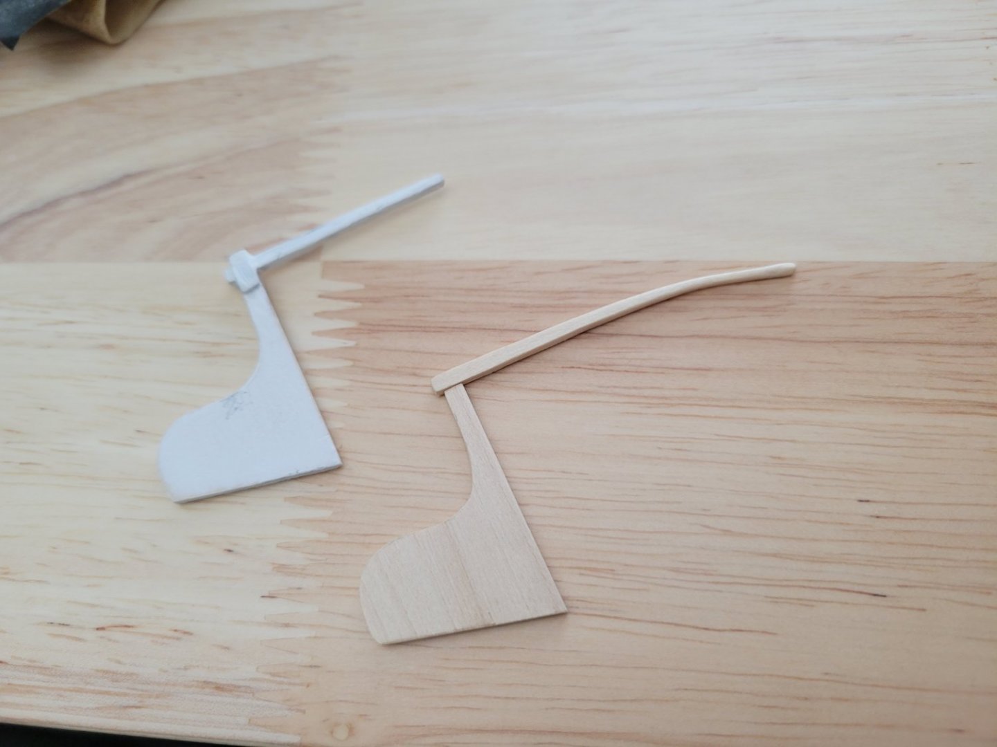
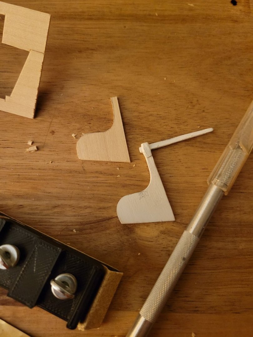
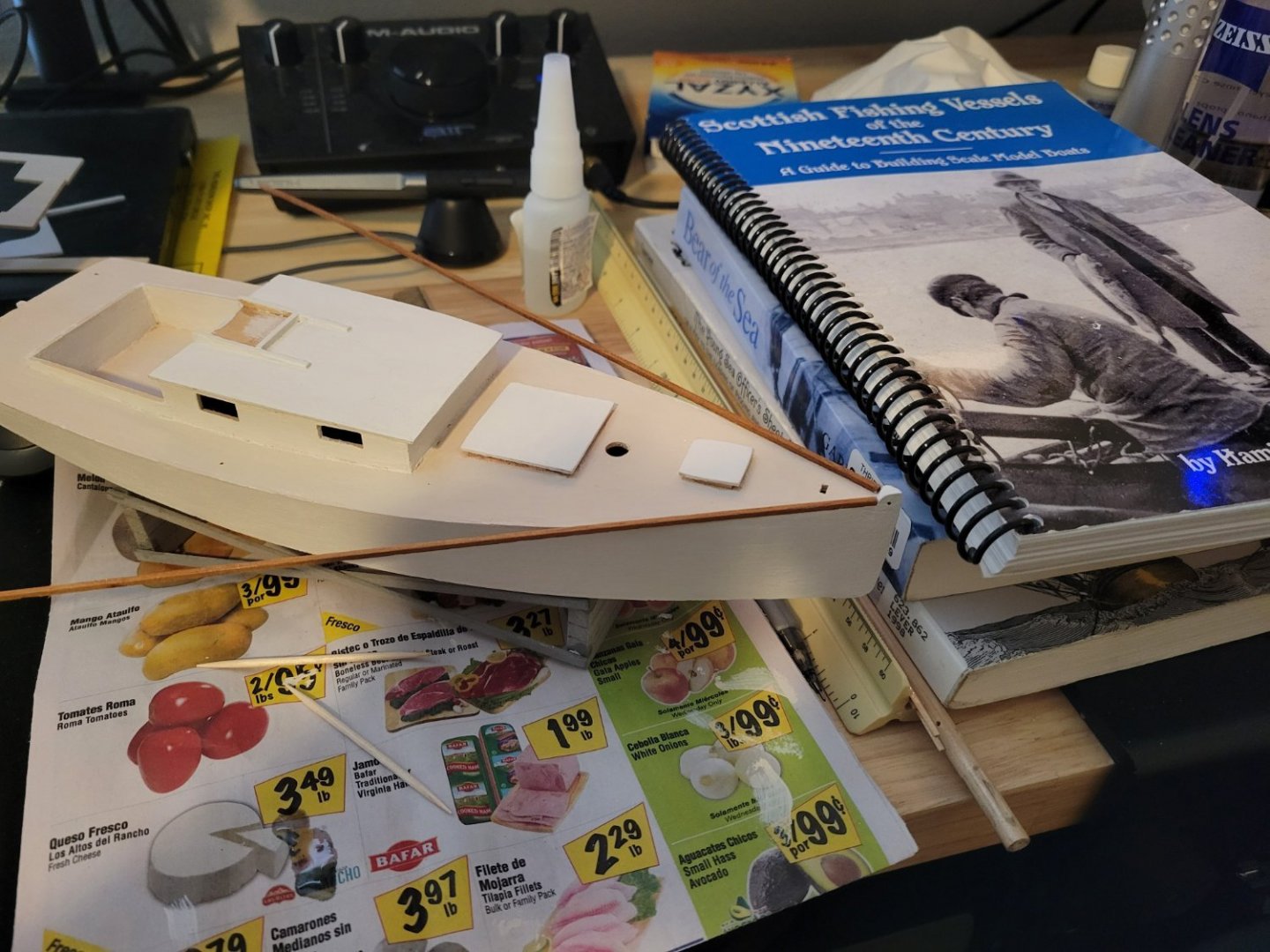
Thanks Roger, great additional points! I was hesitant to treat this model as a [small] pleasure yacht because my work so far (starting from back when I was a kid; I've had this kit for a long time ) is honestly a bit rough. There a couple of alignment/fit issues from when I originally assembled the hull shape as a kid, and in my opinion, my paint job is pretty rough around the edges. However, if I treat this as a boat produced as a family project (perhaps a father and son building on weekends in the backyard), then I think the "rough-around-the-edges" style would be more acceptable. While I am deciding how I want to configure the cockpit, I went ahead and started working on a new rudder and tiller. Regardless of the seating and cleat configuration, I know I want a longer tiller, so I'm moving forward on that aspect. Image comparing the new tiller to the old. This tiller will be stained and varnished rather than painted, the whole assembly will have a cleaner paint job.
-
All very good points. These boats weren't mass produced and sold off a lot next to a hundred other identical models. There was likely a great deal of variation per owner, skipper, builder, and circumstances. I guess a good analogy for me would be swimming pool cleaners since I did this work for roughly 6 years or so. Pool cleaners don't drive luxury cars around, they drive something that meets the needs of their job that is not too expensive, but of good enough quality to avoid repair expenses etc. Also, since a pool cleaner more or less works out of their vehicle, it kind of becomes something of a refuge between pools, and it's nice if it's relatively comfortable with enjoyable things like AC/heater and audio. I guess a typical work boat is not going to be fancy, luxurious, or eccentric. However, it's probably going to be efficient in both construction costs, reliability, and meeting the needs of the job, and comfortable enough to offer some refuge in the downtime. For me, I guess the question can be modified to what is a practical cockpit configuration with the dimensions presented by the model that someone at the end of the 19th Century might have favored. And there might be a lot of valid answers to that question. I'm hoping Kunhardt's "Small Yachts" will shed some light once I get it. mnl, it sounds like you either live or have lived in the vicinity of the Chesapeake Bay. Also, both of you guys, Wefalck and mnl, obviously have solid sailing experience. I really appreciate it; I think it's very valuable for this discussion and I probably would never find this type of info through just researching on my own.
-
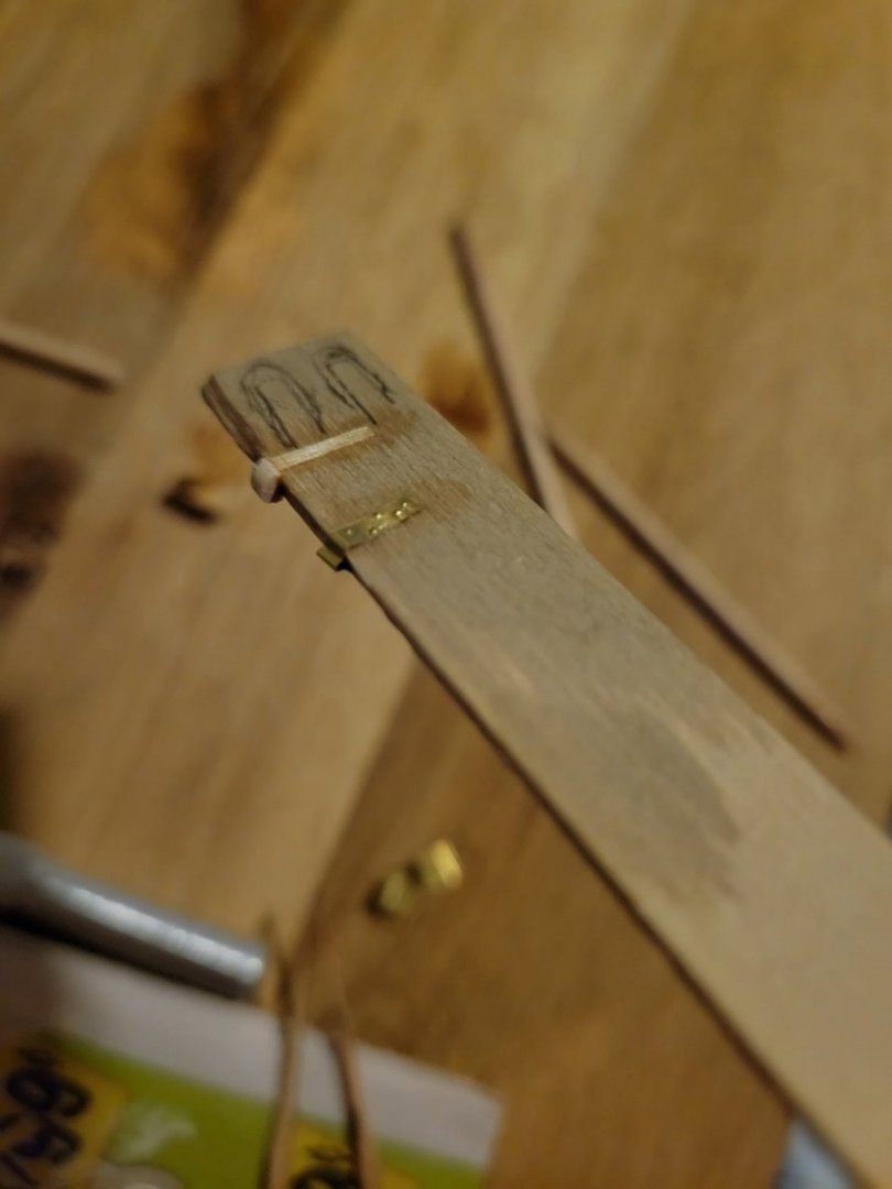
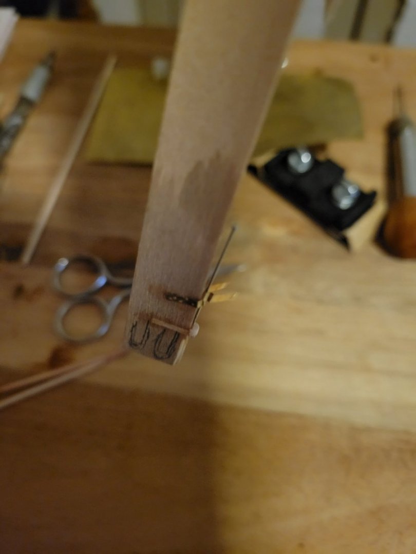
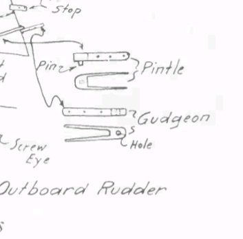
Pintle/Gudgeon Experimenting I'm currently planning customization of the boat's cockpit and have a book on the way in the mail that should help. In the meantime, I'm experimenting with a couple of different ways to make pintles and gudgeons for the rudder. Either option would be painted black before gluing to the stern post and rudder. Which option do you like best? The wooden gudgeon was inspired by a drawing I found by Howard Chapelle. It would still need a hole drilled through which I would do before gluing. I also have slightly thicker wood strips that I would use for the sides. This was made by cutting off a little piece from a dowel and then cutting that in half. Then that was glued onto to edge of the scrap wood, and the strips were glued on the sides. The metal option was made by cutting a little strip from a brass sheet and forming it around a 1/16" piece of scrap wood and a little pin. I liked how easy it was to form the dimples by pressing a sharp point in from behind. The metal option probably looks more like a typical gudgeon. I also decided to make a new rudder assembly mostly because I wasn't satisfied with the current tiller. To start, I cut out a new rudder with X-Acto knife and some sanding.
- 29 replies
-
- 4
-
-
- first build
- Chesapeake Bay Flattie
- (and 2 more)
-
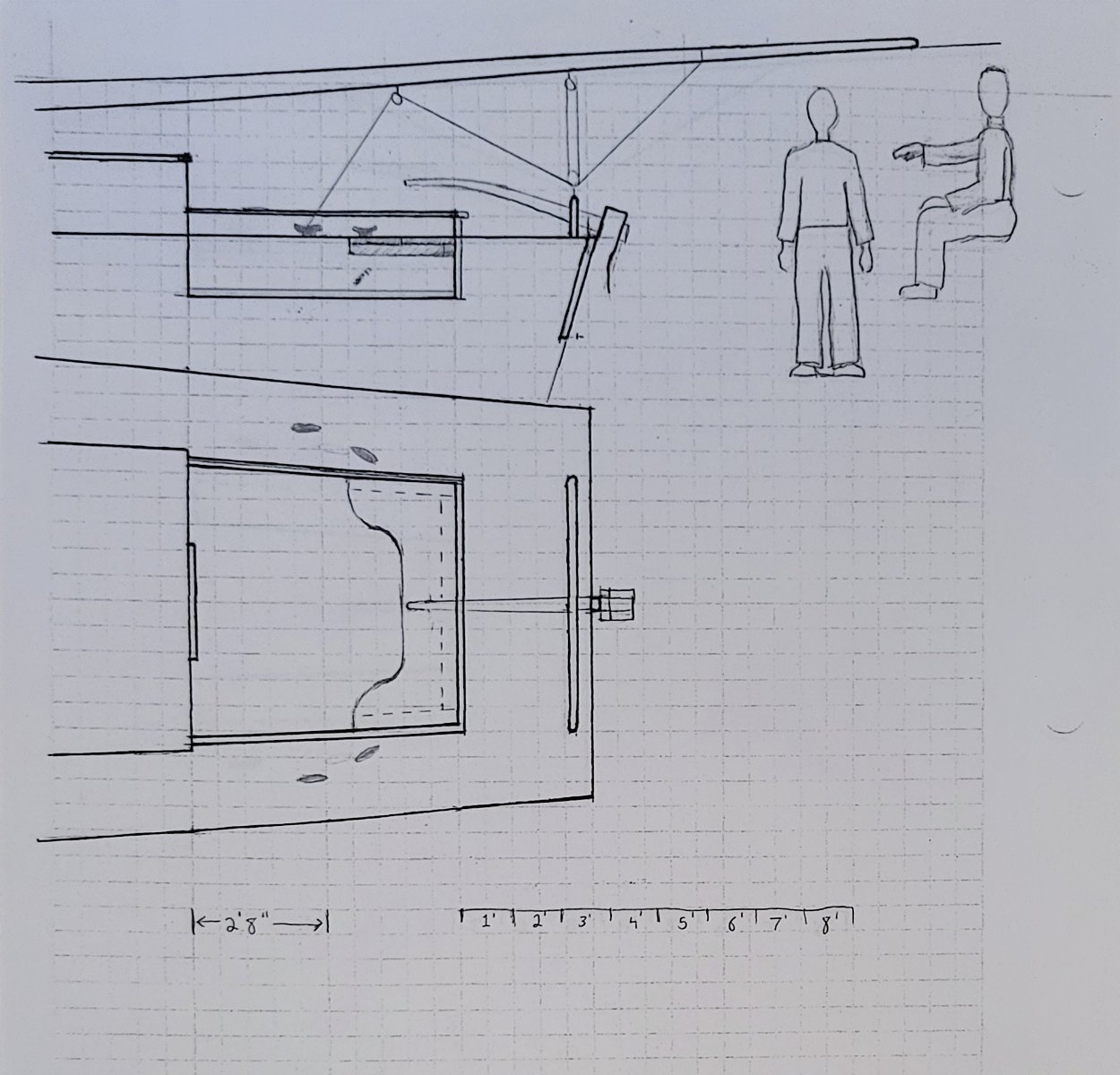
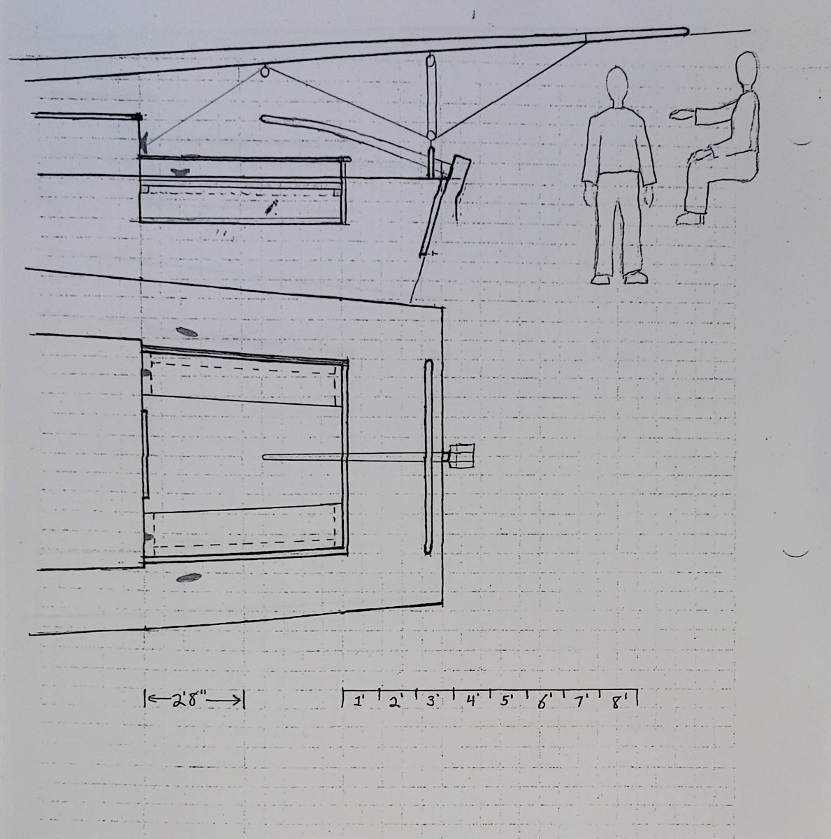
Thank you, this is really helpful information! So Wefalck, you think the helmsman might be sitting against the aft coaming while driving? 20" is a little high for a seat (especially for long periods of time), but not too high. It's also worth noting that the coaming would be too low to provide any real back support in those seats. Chapelle mentions in his section on the flattie that Kunhardt also presents plans and information about flatties in his book "Small Yachts". Chapelle mentions that the flattie in Kunhardt's book has less curve in the sheer and is setup more like a yacht than a working boat. This sounds a lot like the boat from the kit I'm building. I went ahead and ordered a copy of "Small Yachts" hoping the plans will be detailed enough to give some more insight on how my boat would have been set up in those times. (I also think these books will be great reference material for future projects). One thought I have about option 1 is that no one would probably ever sit right in the middle of the seat while under sail, right? I was thinking of narrowing the middle of the seat and having more curve to make sitting in the corners more comfortable. I also though of adding a bulge in the aft part of the seats in option 2 to make it easier to sit closer to the tiller. Uploaded a couple of pictures to demonstrate what I mean. Of course my goal is to get as close to how it would have been set up at the end of the 19th century, not what would be most comfortable for me right now.

-
So maybe the tiller from option 2 and the seat from option 1? What do you think of the cleating the main to the rear cabin bulkhead in option 2? Bad idea? I think that you could comfortably reach the tiller in option 2, but it could be a problem when you have to push the tiller to leeward. I should try to find out some info on tiller extensions around that time period.
-
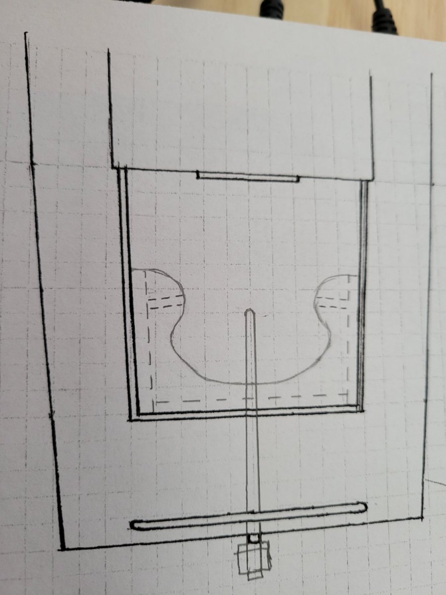
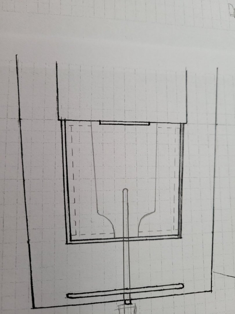
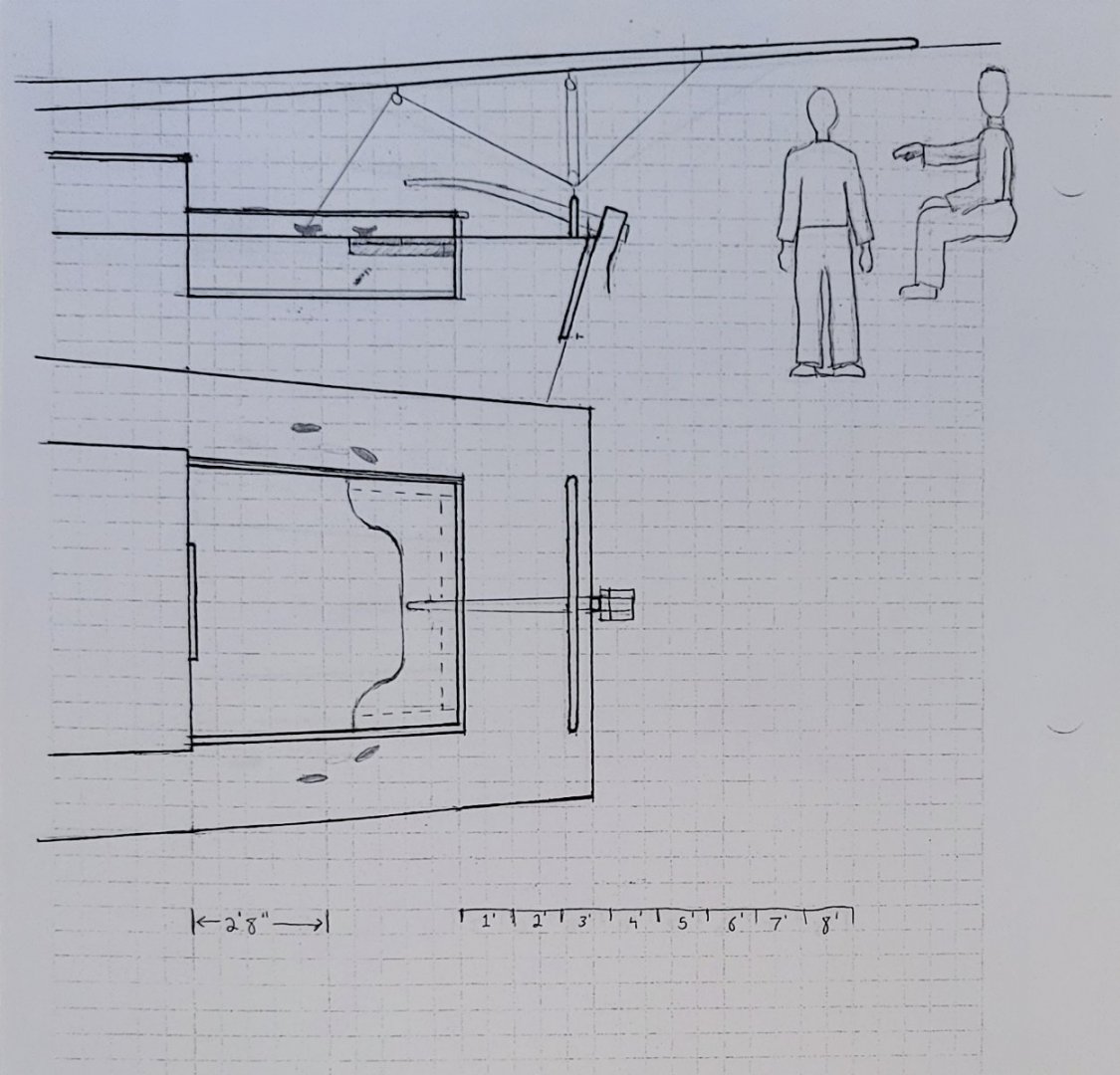
That's a great idea and something that will probably also help a lot in future models. I'll just need to secure some wire or twisty ties. For now, I've some a couple of sketches to brainstorm cockpit seating, tiller, and cleat configuration. I dug up some old graph paper from engineering school, laid out the overhead and profile view of the cockpit at the exact dimensions of the model. Then I drew some simple figures using a human anatomy tutorial (someone roughly 5' 10"), made some copies and drew a couple examples. How do these look? How could they be improved? (First one is mostly copying the concepts from the Chapelle plan)

-
Enjoying the build! I like your approach to getting little details as accurate as you can. I think it will pay-off in later parts of the build
- 61 replies
-
- 2
-
-
- Lowell Grand Banks Dory
- Model Shipways
- (and 1 more)
-
Quick correction, I made a silly mistake with the cockpit measurements. Since I was using a tape measure, I started at the 1" Mark. Each measurement got an extra inch. Corrected measurements after multiplying by scale: Cockpit length fore-and-aft - 5' 4" Cockpit width at cabin - 5' 4" Cockpit width aft - 5' Depth is still 20"
-
That really helps. I can definitely see myself looking at this model 10 years from now and regretting not doing the extra. I will probably go ahead and spend the extra time to build something I can look at later and be happy with myself that I went the extra mile. I suppose the next step is to plan the cockpit. I'll try to do some drawings and play with some ideas. If you guys don't mind, I would love to share any drawings and see what you think. I think building another rudder and tiller assembly is in order with a longer tiller, or a hiking stick (longer tiller will no doubt be easier) What do you guys think about the cockpit flooring from the perspective of: what if that was the floor of the cockpit for your own yacht? How happy/unhappy would you be? The floor on my model is not glued down yet, so it will not be a huge deal to make another one. So far I haven't found any evidence of what the cockpit floor looked like for a working boat on Chesapeake Bay in late 19th or early 20th century.
-
I'm having some good discussion in this thread about my question: Thread I'm thinking the more fundamental question is: do I try to make the cockpit more realistic, or do I just complete the kit and save the greater detail for another kit?
- 29 replies
-
- 2
-
-
- first build
- Chesapeake Bay Flattie
- (and 2 more)
-
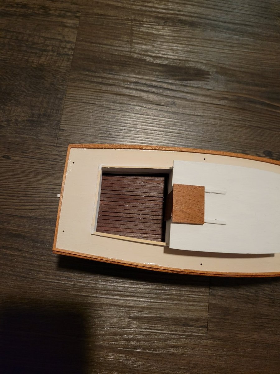
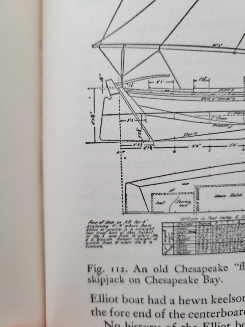
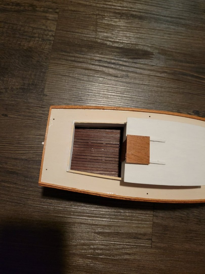
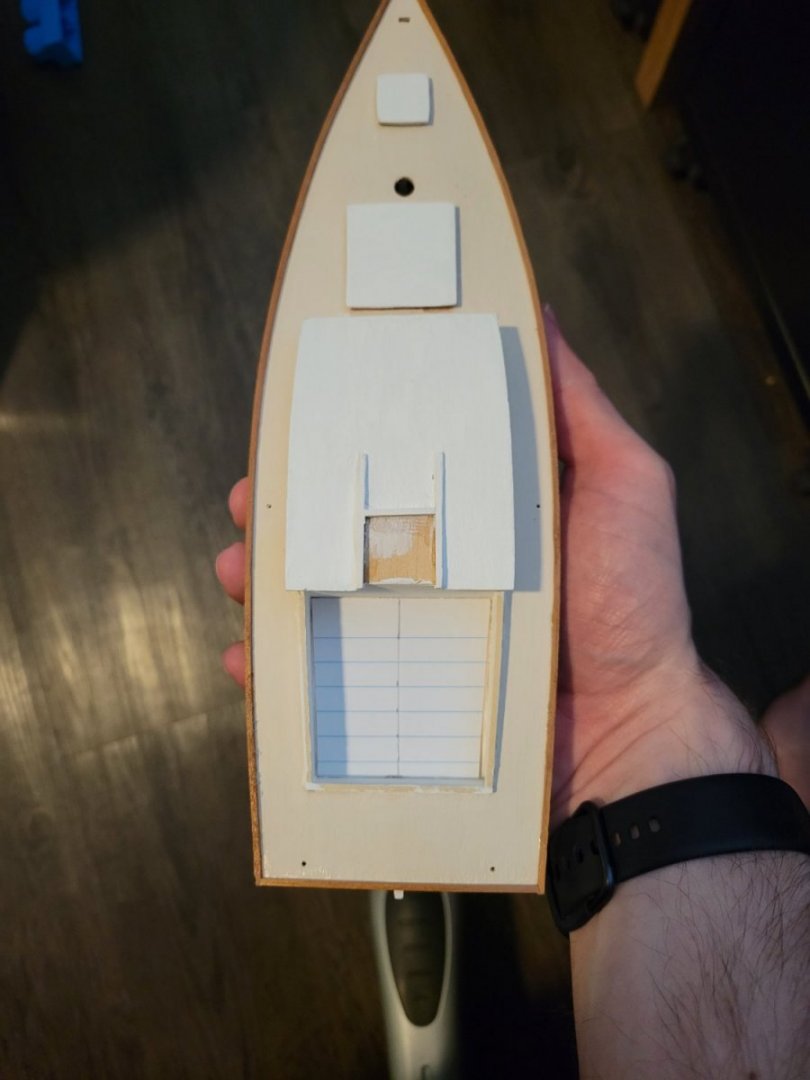
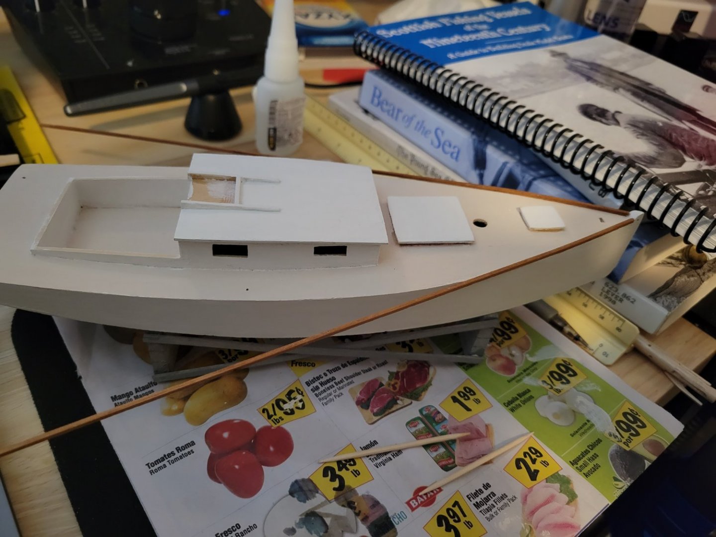
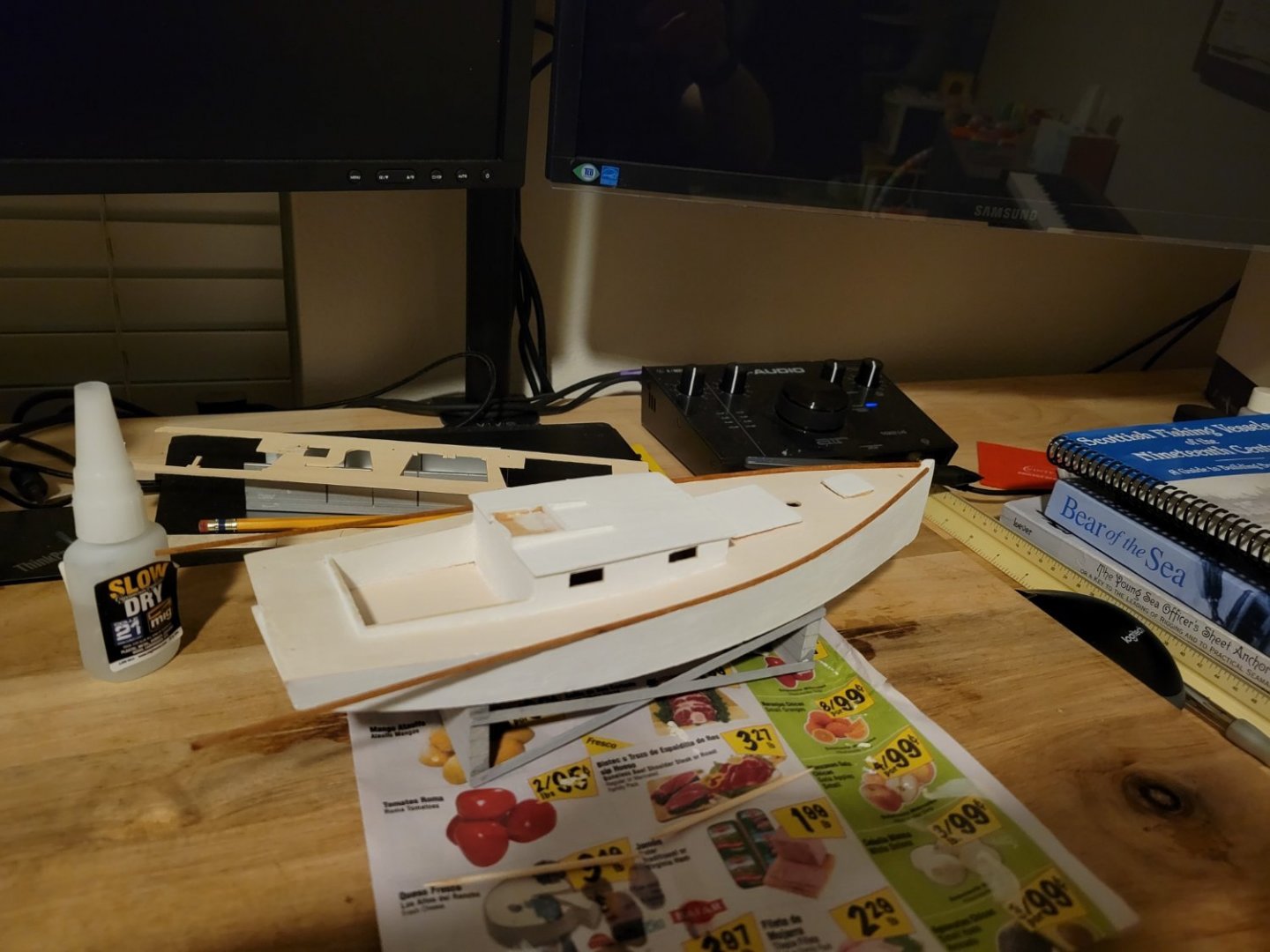
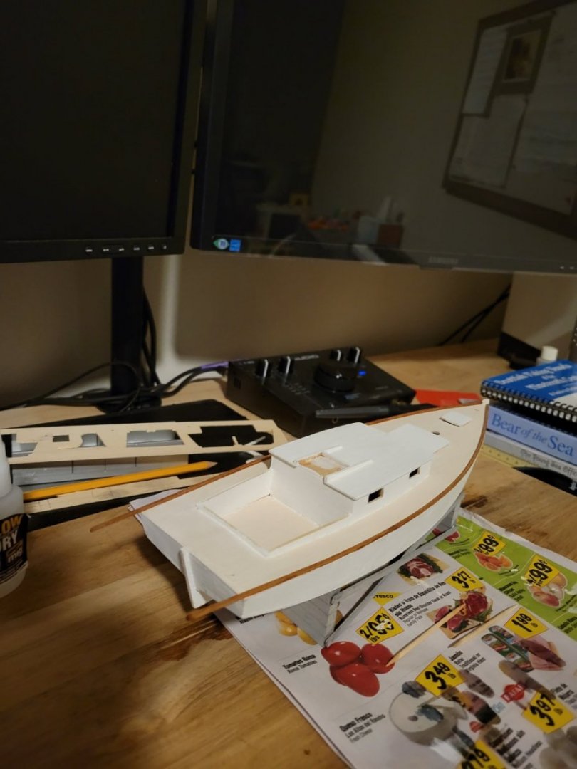
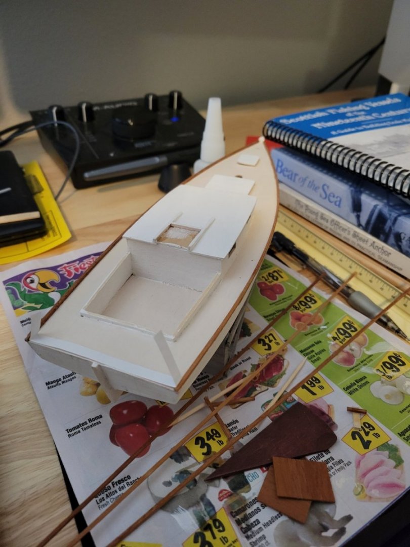
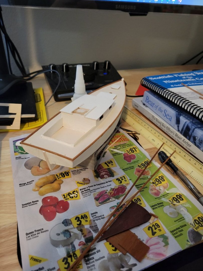
Great points So far, the closest thing I've found to a real example of a Chesapeake Bay Flattie workboat is plans from Howard Chapelle's "American Small Sailing Craft". It seems that the cockpit on this boat addresses many of the points you guys are bringing up. The cockpit is smaller. There is a bench along the inside of the coaming aft shaped to allow someone sit on one side angled inward. The tiller extends further into the cockpit area. It appears there is a cleat on each side for the main sheet, and slightly further forward, a cleat for the jib sheets on each side. These cleats are outside the coaming on the deck. Also, the main sheet is configured more how Wefalck described. I'm wondering how far I should go with this first model. I wonder if I should just complete the kit to specs and wait to get more detailed on another model or try to make the cockpit more realistic now. It's definitely not going to be 100% historically accurate to the plans in Chapelle's book. This is the current state of the model. I added a custom floor to the cockpit without any historical reference, just inspired by other build logs. Companionway hatches are not glued down yet.
-
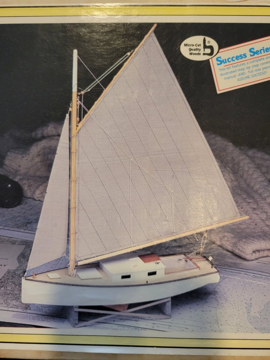
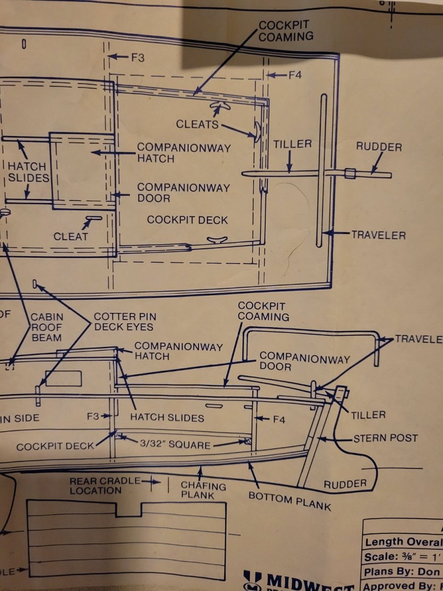
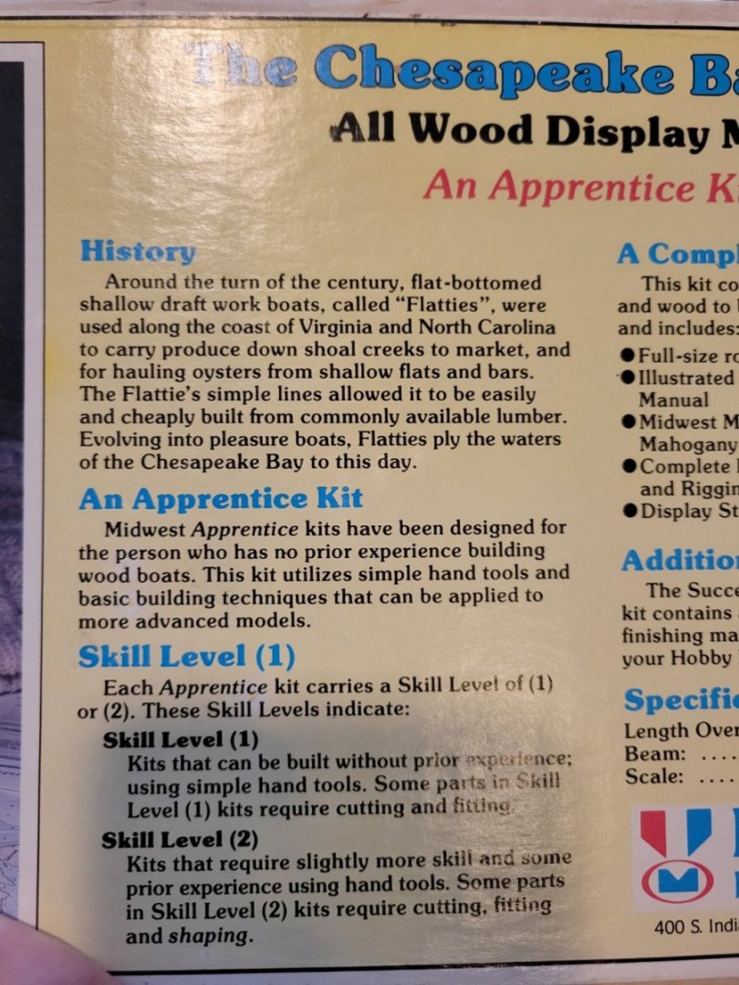
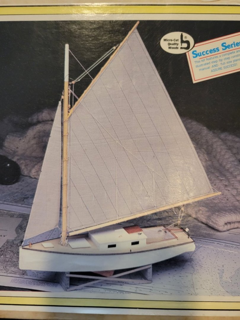
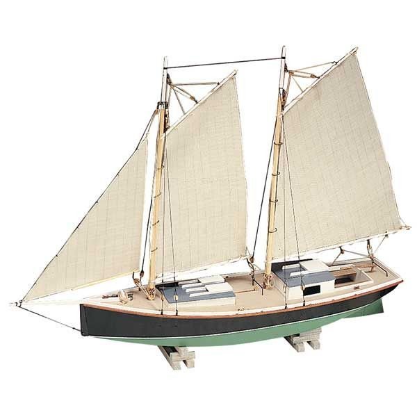
Wefalck, thanks for your reply. I have never sailed and am a beginner at modeling as well, so I really appreciate this kind of discussion. I'm attaching a few more photos to help make the context more understandable (trying not to upload the entire plans. I don't think that would be very ethical). You can see both the description and an entire finished model (the photo I uploaded before didn't give you much to go by) According to Midwest's historical description, this could either be a working or pleasure boat. I suspect a pleasure boat should probably have a longer cockpit and cabin. I would like to think the long bow with hatches indicates the boat is built for transporting produce. I was intending to treat it as a working boat (I think my paint job is a little rough for a pleasure boat 😆 ) According to the 1:32 scale and measurements of the model/plans, the size of the cockpit on the full-size boat would be 8' fore-and-aft, 7' wide aft, and roughly 7.5' wide at the cabin. It would be 20" deep from the floor to the coaming rails. Also, to clarify, the cleats on the sides of the cockpit are for the jib sheets (according to the directions), and the cleat at the back of the cockpit is supposed to be for the main sheet. The cleat for the centerboard is on the cabin roof (more than 8' away from the stock tiller). Halyards are secured at the bottom of the mast. I suspected that the coaming rails might be low enough on the full-size boat to serve as seats, but thought it would be fun to build some seats that run along the sides of the cockpit. Midwest Product's "Sharpie Schooner" has a similar sized cockpit with such seating. Also looks like the main sheet is more similar to the setup you described.
-
Very nice! Looks to me like a sprit sail. Interesting that it's lashed to the mast instead of suspended with a snotter. Anyhow, I love these types of boats and yours looks great! It makes me think of a John Welsford 6m Whaler (which I'm sure is inspired by boats like this). I've considered this kit at some point. Looks fun!
- 16 replies
-
- 1
-

-
- whaleboat
- Artesania Latina
- (and 3 more)
-
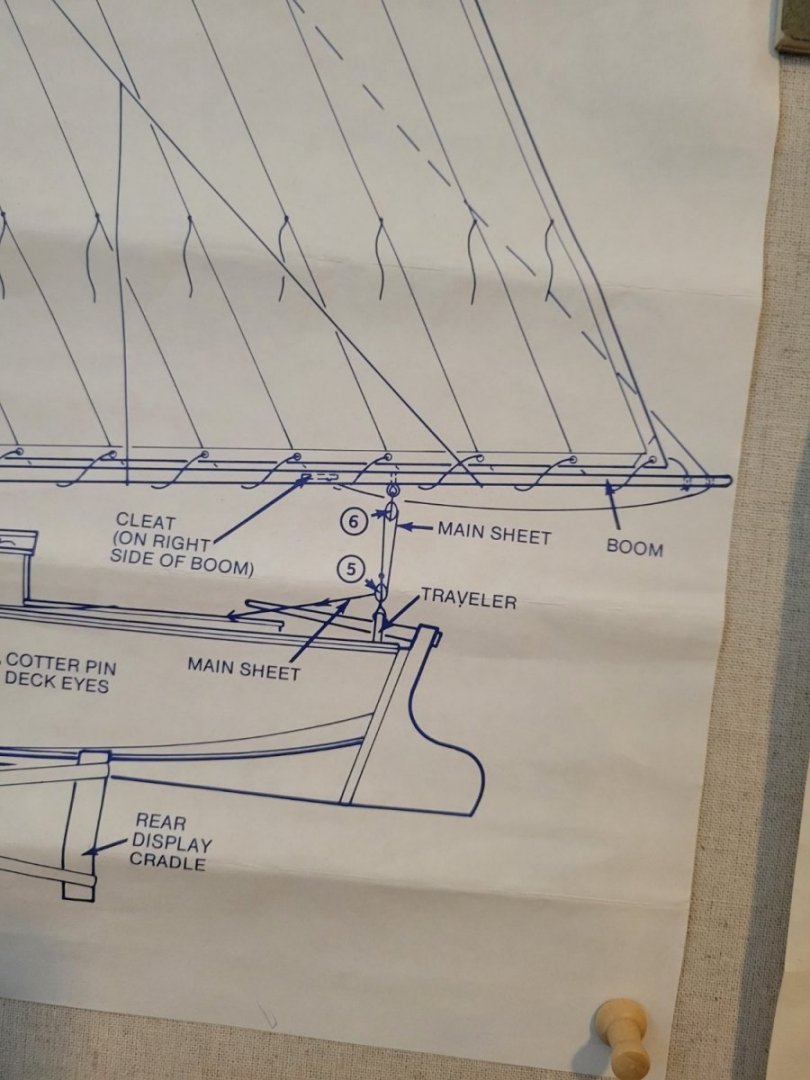
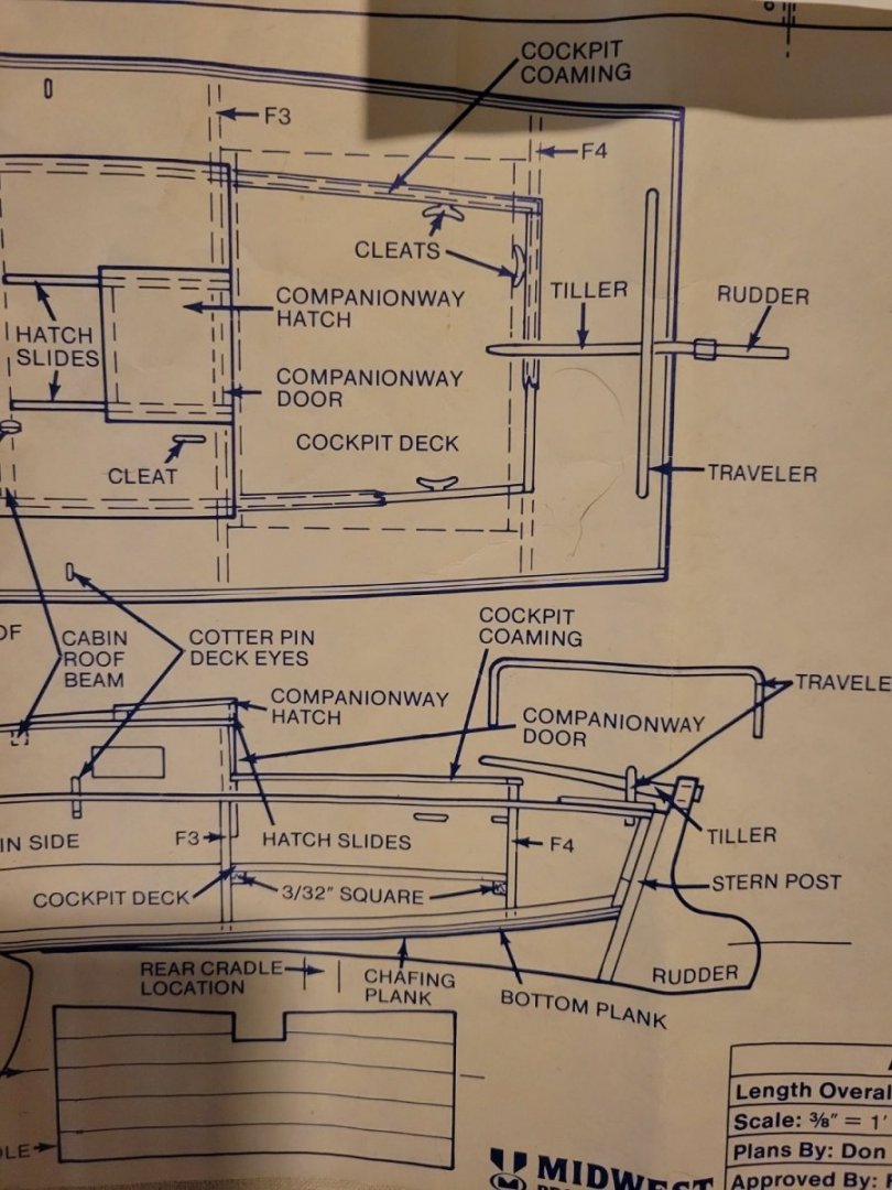
Thanks for the replies everyone! If I understand correctly, in the plans for the kit, the lines actually need to take a sharp angle over the coaming rail. This would go against the guideline of a being fair, right? I attached an image of the relevant part of the plans. Very good points. Hard to know the little details that work best in a particular scenario without being there and experiencing it first-hand. I wonder if Midwest Product's choice of location was based off of this type of knowledge? That is also an interesting idea to switch to other belaying devices. I saw some photos of small vessels with belaying pins, and it looked pretty good. Researching some boat-building forums indicates belaying pins might be less desirable for the main sheet compared to a cleat. One thing's certain: using belaying pins would be quite a unique customization to my kit. I'm looking for images of similar boats to see how their running rigging is set up. I've definitely seen cleats positioned just outside the cockpit either on the deck or outside surface of the coaming. Great point! In the kit, most of the cleats are definitely within reach of someone with a hand on the tiller except maybe the cleat for the centerboard. That might be out of reach without modification of the tiller.
-
Hi everyone! I'm wondering if anyone has any knowledge about guidelines regarding the location of cleats for securing sheets and halyards near (or in) the cockpit on smaller 19th Century working boats. Is it pretty much up to the builder, owner, or skipper? Does this very wildly by design? Are there general guidelines? The context of my question is that I'm considering relocating the sheets and halyard cleats on a Chesapeake Bay Flattie model kit (Midwest Products) in order to put seats in the cockpit.
-
Question Now I'm caught up to the current state of the build, I have a decision to make. I'm considering adding benches to the cockpit; what do you guys think? I would just do it, but there is an issue that gives me pause: with a scale of 1:32, the height of the coaming rails above the cockpit floor would be about 20" on the full-size vessel. This might actually be low enough to serve as the cockpit seat, and a bench may be unnecessary. In addition, putting the benches at a practical height would interfere with the placement of the cleats specified by the kit's plans. A full-size height of at least 12" converts to at least 3/8" on the model which is exactly where the cleats are specified to be. So if I added benches, I would need to relocate the cleats, and I'm not sure of any rules or guidelines about where cleats for the sheets and halyard should be located on a vessel like this. Does anyone have any knowledge or opinions related to this?
- 29 replies
-
- 2
-
-
- first build
- Chesapeake Bay Flattie
- (and 2 more)
-
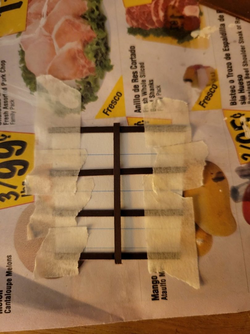
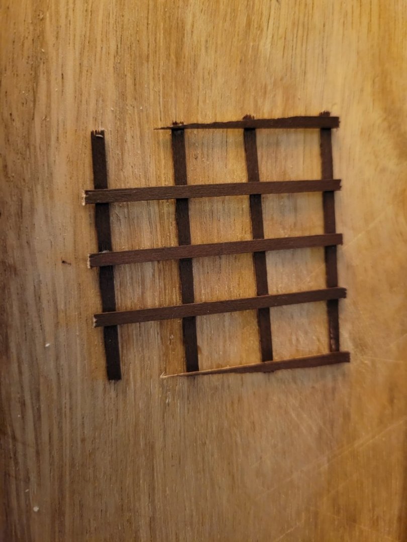
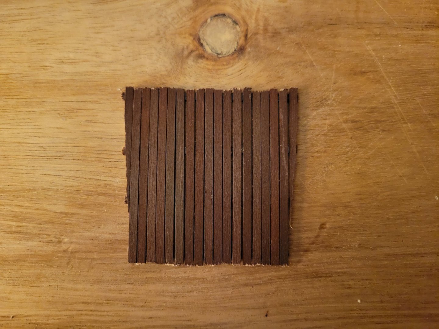
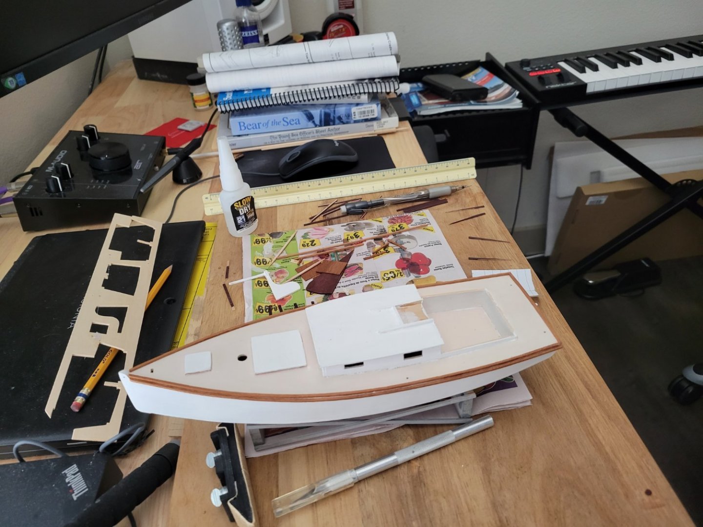
Customization: cockpit plank flooring Initially, I was planning to just finish the model as specified in the kit. However, seeing how others on this forum have customized this kit and seeing how pretty she was looking with the mahogany rails caused me to decide to spend some more time and have some fun with a little customization. The first customization is planked flooring. I cut a piece of paper to fit the cockpit floor and used that as my guide for assembling the flooring. I taped the cross planks to the paper and glued the first plank in order to get everything aligned properly. I wasn't sure exactly how the spacing needed to be, so I glued on planks at the 1/4 positions and planks at the end (cut to an angle) Then I filled in the gaps I built it oversized so that I could trim and sand it to fit.

- 29 replies
-
- 6
-
-
- first build
- Chesapeake Bay Flattie
- (and 2 more)
-
Adding the toe rails and rub rails I glued on the toe rails and rub rails. I was a little apprehensive about this since the directions basically just say to put a bead of glue on the rail and then put it on. Since the deck curve doesn't perfectly match the curve of the rail when bent from two ends, it was not going to be easy to hold the whole thing in place while the glue dried, and I don't have any clamps that will work for this scenario. So I just glued the rails bit by bit. I also used a strip of paper to determine the length of the aft rail. I made a mistake in that while focusing on getting the port rub rail vertically aligned properly with the toe rail, I accidentally moved it back from the stem a little, so it doesn't horizontally align with the toe rail at the bow.
- 29 replies
-
- 4
-
-
- first build
- Chesapeake Bay Flattie
- (and 2 more)
-
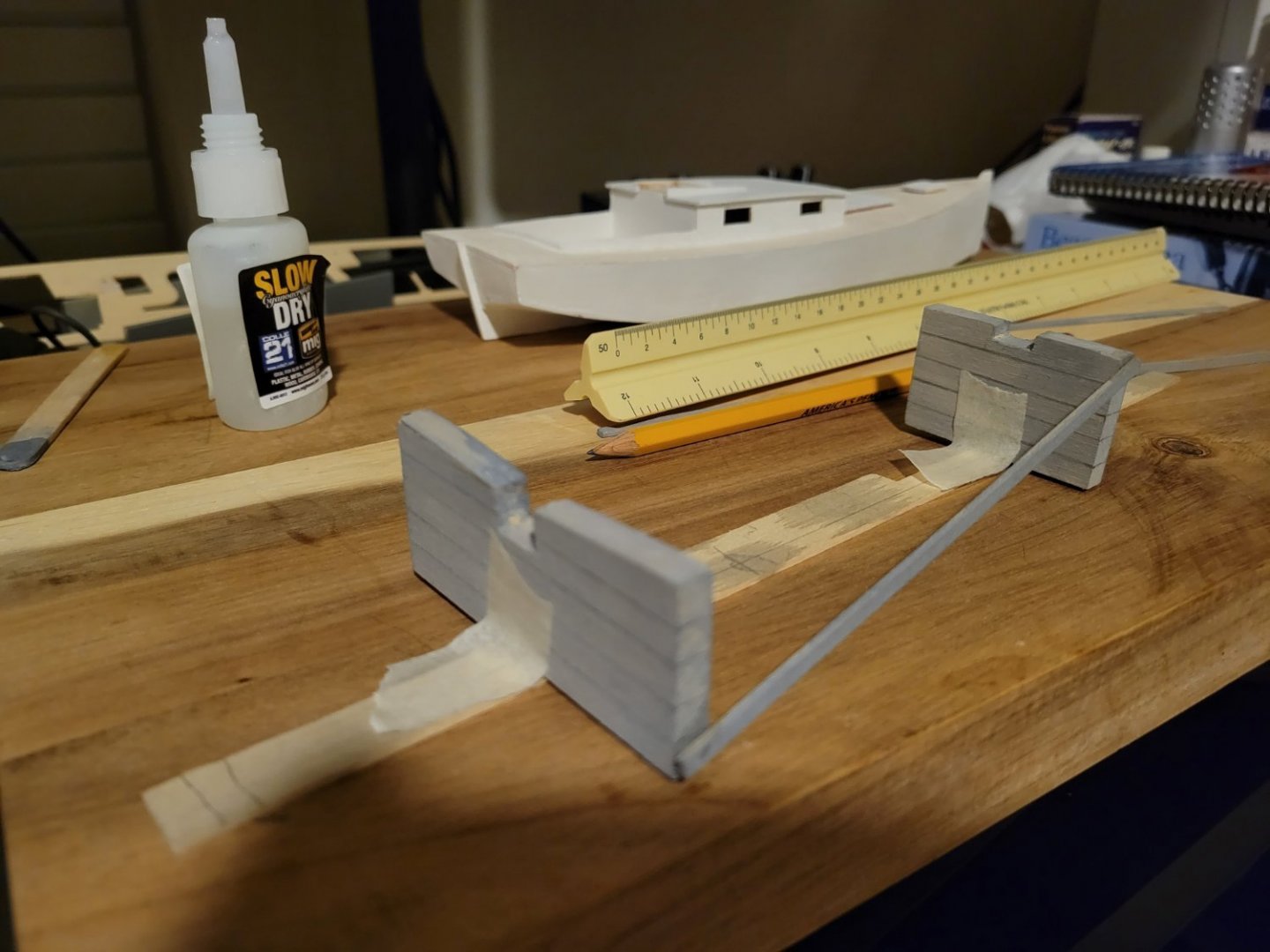
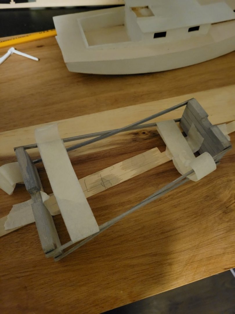
Assembly of the display cradle: I used a super high-tech method to align the display cradle blocks while gluing on the planks: scrap wood and masking tape. I marked the distance from the plans on the scrap and centered the blocks, keeping them in place with tape: I encountered a challenge in that the planks bend around each other which puts them under tension. This makes it more difficult to bond the outside planks. In hindsight, I probably could have slightly bent the planks to ease the tension. I actually needed to use some epoxy on one of the corners to get a strong enough bond. I used some high-tech masking tape to gently clamp the outside planks until the glue fully cured. Tape might not be the best solution when considering the finish, but this assembly is supposed to look old, rustic, and worn, so I wasn't too concerned. In hindsight, if I did this again, I might sand a slight bevel in the blocks to give a better surface to glue the planks. But perhaps the "sloppy" angles was intended as part of the rustic and worn aesthetic? Actually, I could have gone further and sanding a slightly different bevel on each penciled in piece of lumber to both get a better glue surface and enhance the impression of separate pieces of lumber and rough construction. I'm learning a lot of lessons building my first model that I will take with me to future models.
- 29 replies
-
- 2
-
-
- first build
- Chesapeake Bay Flattie
- (and 2 more)
-
I've been interested in this kit, so very interested to see how your build goes. I'm about halfway through reading the Milton Roth book "Ship Modeling From Stem to Stern" and enjoying it. I bet having all that foundational knowledge is going to help you with a good approach to this model. It will probably be fun to see the stuff you read about becoming reality in your model.
-
Thanks for the warm welcome!